SRv6-MPLS L3 Service Interworking Gateways

This chapter focuses on the crucial role of SRv6-MPLS L3 service interworking gateways in bridging disparate network domains, ensuring seamless service continuity between SRv6 and MPLS infrastructures. It details how these gateways facilitate the extension of L3 EVPN services, supporting migration strategies and enabling communication across domains with potentially different Segment Identifier (SID) formats. The chapter covers the operational mechanisms, benefits, and configuration of interworking gateways, including scenarios for dual-connected Provider Edges (PEs) and route re-origination for optimized scalability and interoperability.

SRv6 MPLS L3 service interworking gateway

An SRv6 MPLS L3 service interworking gateway is a gateway that

  • extends L3 services between MPLS and SRv6 domains by providing service continuity on the control plane and data plane

  • enables SRv6 L3VPN domains to interwork with existing MPLS L3VPN domains and supports migration from MPLS L3VPN to SRv6 L3VPN, and

  • provides both transport and service termination at the gateway node.

Table 1. Feature History Table

Feature Name

Release

Description

Identical Route Distinguisher (RD) for Interworking Gateways between MPLS and SRv6 Domains

Release 25.1.1

Introduced in this release on: Fixed Systems (8010 [ASIC: A100])(select variants only*)

*This feature is supported on Cisco 8011-4G24Y4H-I routers.

Identical Route Distinguisher (RD) for Interworking Gateways between MPLS and SRv6 Domains

Release 24.4.1

Introduced in this release on: Fixed Systems (8200 [ASIC: P100], 8700 [ASIC: P100, K100])(select variants only*); Modular Systems (8800 [LC ASIC: P100])(select variants only*)

*This feature is supported on:

  • 8212-48FH-M

  • 8711-32FH-M

  • 8712-MOD-M

  • 88-LC1-36EH

  • 88-LC1-12TH24FH-E

  • 88-LC1-52Y8H-EM

Identical Route Distinguisher (RD) for Interworking Gateways between MPLS and SRv6 Domains

Release 24.1.1

You can now configure the same Route Distinguisher (RD) for interworking gateways catering to both MPLS and SRv6 domains that help conserve hardware resources, reduce the BGP table scale and minimize the processing load on routers. At the same time, it ensures seamless connectivity across SRv6 and MPLS L3 EVPN domains, thus promoting interoperability and efficiency in modern network environments.

Previously, a unique RD was required to extend L3 services between MPLS and SRv6 domains resulting in higher router load and resource consumption, which could have affected performance.

SRv6/MPLS L3 Service Interworking Gateway (SRv6 Micro-SID)

Release 25.1.1

Introduced in this release on: Fixed Systems (8010 [ASIC: A100], 8700 [ASIC: K100])(select variants only*)

*This feature is supported on:

  • 8712-MOD-M

  • 8011-4G24Y4H-I

SRv6/MPLS L3 Service Interworking Gateway (SRv6 Micro-SID)

Release 24.4.1

Introduced in this release on: Fixed Systems (8200 [ASIC: P100], 8700 [ASIC: P100])(select variants only*); Modular Systems (8800 [LC ASIC: P100])(select variants only*)

*This feature is supported on:

  • 8212-48FH-M

  • 8711-32FH-M

  • 88-LC1-36EH

  • 88-LC1-12TH24FH-E

  • 88-LC1-52Y8H-EM

SRv6/MPLS L3 Service Interworking Gateway (SRv6 Micro-SID)

Release 7.8.1

This feature enables you to extend L3 services between MPLS and SRv6 domains by providing service continuity on the control plane and data plane.

This feature allows for SRv6 L3VPN domains to interwork with existing MPLS L3VPN domains. The feature also allows migration from MPLS L3VPN to SRv6 L3VPN.
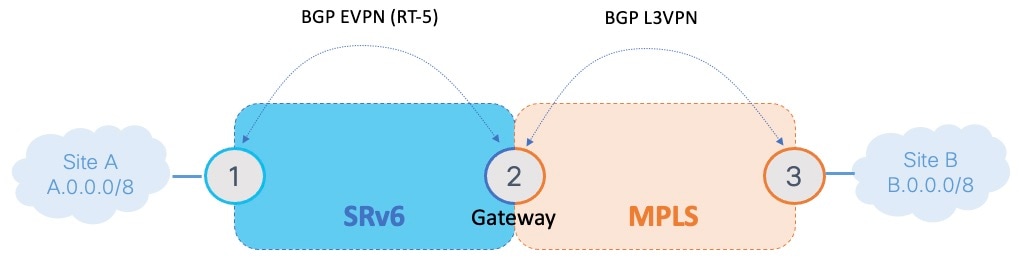
Gateway mechanism

The gateway performs these key actions to enable interworking:

  • Imports service routes: The gateway imports service routes received from one domain (MPLS or SRv6).

  • Re-advertises exported service routes: It re-advertises exported service routes to the other domain (next-hop-self).

  • Stitches the service: The gateway stitches the service on the data plane (uDT4/H.Encaps.Red ↔ service label).

Virtual Routing and Forwarding (VRFs) on the gateway node are configured with two sets of route targets (RTs): MPLS L3VPN RTs and SRv6 L3VPN RTs (referred to as stitching RTs).

To understand the detailed control-plane and data-plane behaviors for specific traffic flows, refer to these process topics:

How MPLS-to-SRv6 control-plane and SRv6-to-MPLS data-plane traffic works

This process describes the control-plane behaviors in the MPLS-to-SRv6 direction for traffic that flows in the SRv6-to-MPLS data-plane direction.

Summary

The process involves BGP L3VPN updates exchanged between Node 1 (MPLS domain) and Node 2 (gateway), which then re-originates updates into the SRv6 domain. Subsequently, traffic from Site B is encapsulated by Node 3, processed by Node 2, and finally forwarded by Node 1 to Site A.

Workflow

Figure 1. Topology for MPLS-to-SRv6 control-plane and SRv6-to-MPLS data-plane traffic flow

These stages describe how the SRv6/MPLS L3 service interworking gateway works, covering both control plane and data plane flows.

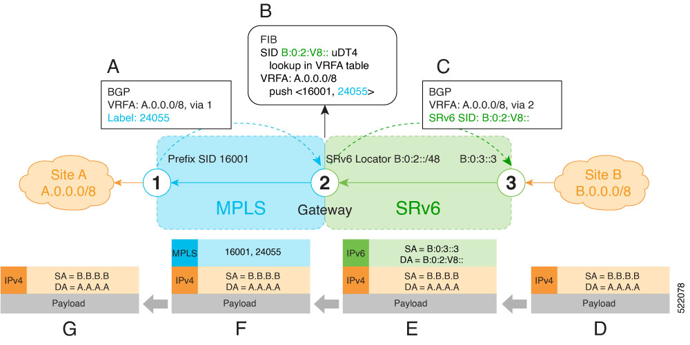
  1. (A) As illustrated by A in the figure, Node 1 advertises a BGP L3VPN update for prefix A.0.0.0/8 with RD corresponding to VRFA, including the MPLS VPN label (24055) assigned to this VRF, in the MPLS domain. Refer the part A in the figure.
  2. (B) Node 2 (gateway) imports the BGP L3VPN update and programs its FIB:
    • Prefix A.0.0.0/8 is programmed to impose an MPLS VPN label (24055) and the prefix SID MPLS label (16001) of the BGP next-hop (Node 1)
    • "Endpoint with decapsulation and IPv4 table lookup" function (uDT4) of B:0:2:V8:: is allocated to VRFA

      Note


      SRv6 uDT4 function value "V8" is not a valid hex number, however it is used for illustration purposes to remind you of its connection to a VRF.

    Note


    The gateway follows per-VRF label and per-VRF SID allocation methods.
  3. ( C) Node 2 re-originates a BGP L3VPN update for the same prefix, including the uDT4 function (B:0:2:V8::) allocated for the VRF, in the SRv6 domain.
  4. (D) Site B sends traffic to an IPv4 prefix (A.A.A.A) of Site A.
  5. (E) Node 3 Encapsulates the payload in an outer IPv6 header with destination address (DA) equal to the uDT4 function (B:0:2:V8::).
  6. (F) Node 2 performs the following actions:
    • Removes the outer IPv6 header and looks up the destination prefix
    • Pushes the MPLS VPN label (24055) and the prefix SID MPLS label (16001) of the BGP next-hop (Node 1)
  7. (G) Node 1 pops the MPLS VPN label, looks up the payload destination address (A.A.A.A), and forwards to Site A.

How SRv6-to-MPLS Control-Plane and MPLS-to-SRv6 Data-Plane Traffic Works

This process describes the flow of control plane information from an SRv6 domain to an MPLS domain, and the subsequent forwarding of data traffic from the MPLS domain to the SRv6 domain through an SRv6/MPLS L3 Service Interworking Gateway. This interworking ensures seamless service continuity and efficient traffic routing across different network segments.

Summary

In this process, an L3VPN PE in the SRv6 domain (Node 3) advertises a prefix. The SRv6/MPLS L3 Service Interworking Gateway (Node 2) imports this advertisement, programs its FIB, and re-originates the prefix into the MPLS domain. Subsequently, traffic originating from the MPLS domain (Site A via Node 1) is encapsulated by Node 1, processed and re-encapsulated by the gateway (Node 2) for the SRv6 domain, and finally forwarded by Node 3 to its destination (Site B

Workflow

These stages describe how the SRv6-to-MPLS control plane and MPLS-to-SRv6 data plane interworking process functions:

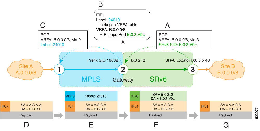
  1. (A) Node 3 advertises a BGP L3VPN update for prefix B.0.0.0/8 with RD corresponding to VRFA, including the SRv6 VPN SID (B:0:3:V9::) assigned to this VRF, in the SRv6 domain, as shown in A of Figure 1.

    Note


    SRv6 uDT4 function value "V9" is not a valid hex number, however it is used for illustration purposes to remind you of its connection to a VRF.
  2. (B) Node 2 (gateway) imports the BGP L3VPN update and programs its FIB, as shown in B of Figure 1.
    • MPLS label 24010 is allocated for VRFA
    • Prefix B.0.0.0/8 is programmed with an "SR Headend Behavior with Reduced Encapsulation in an SR Policy" function (H.Encaps.Red) of B:0:3:V9::

    Note


    The gateway follows per-VRF label and per-VRF SID allocation methods.
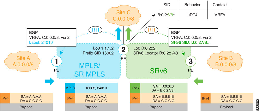
  3. (C) Node 2 re-originates a BGP L3VPN update for the same prefix, including the MPLS VPN label (24010) allocated for the VRF, in the MPLS domain, as shown in C of Figure 1.
  4. D: Site A sends traffic to an IPv4 prefix (B.B.B.B) of Site B, as shown in D of Figure 1.
  5. (E) Node 1 encapsulates incoming traffic with the MPLS VPN label (24010) and the prefix SID MPLS label (16002) of the BGP next-hop (Node 2), as shown in E of Figure 1.
  6. (F) Node 2 performs the following actions, as shown in F of Figure 1.
    • Pops the MPLS VPN label and looks up the destination prefix
    • Encapsulates the payload in an outer IPv6 header with destination address (DA) equal to the H.Encaps.Red function (B:0:3:V9::)

Interworking gateways for L3 EVPN SRv6 and L3VPN MPLS

L3 EVPN Interworking between SRv6 and MPLS is a SRv6 networking solution that

  • extends L3 EVPN services between SRv6 and MPLS domains

  • provides service continuity on both the control plane and data plane, and

  • allows for migration from MPLS L3 EVPN to SRv6 L3 EVPN.

Restrictions of interworking gateways for L3 EVPN SRv6 and L3VPN MPLS

L3 EVPN/SRv6 and L3 EVPN/MPLS Interworking Gateway is supported for IPv4 and IPv6.

How interworking gateways for L3 EVPN SRv6 and L3VPN MPLS operate

The L3 EVPN/SRv6 and L3 EVPN/MPLS Interworking Gateway acts as a central network device. It provides both transport and service termination at the gateway node, enabling the extension of L3 EVPN services between MPLS and SRv6 domains.

For this interworking, VRFs on the gateway node are configured with two sets of route targets (RTs):

  • L3 EVPN/MPLS RTs

  • L3 EVPN/SRv6 RTs (also known as stitching RTs)

Summary

The key components involved in the interworking process are:

  • Gateway node: The central device that performs the interworking functions, connecting and translating between the SRv6 and MPLS domains.

  • SRv6 L3 EVPN domains: Network segments utilizing SRv6 for transport and EVPN for L3 service delivery.

  • MPLS L3VPN domains: Traditional MPLS networks providing Layer 3 VPN services.

  • Virtual Routing and Forwarding instances: Logical routing tables configured on the gateway node to isolate and manage different VPN services.

  • Route targets (RTs): BGP extended communities used to control the import and export of VPN routes between domains, including stitching RTs for interworking. Stitching is the overarching process by which the gateway node integrates the control and data planes of the two distinct domains, often involving specific route targets and re-origination mechanisms.

  • Border Gateway Protocol) The routing protocol used to exchange VPN routing information between the gateway and the respective domains.

The L3 EVPN/SRv6 and L3 EVPN/MPLS Interworking Gateway facilitates seamless service continuity between SRv6 and MPLS domains. It achieves this by importing and re-originating service routes in the control plane and by performing necessary encapsulation, decapsulation, and lookup operations in the data plane. This process supports traffic flow in both directions and enables migration scenarios.

Workflow

These stages describe how interworking gateways for L3 EVPN SRv6 and L3VPN MPLS operate:

  1. The gateway prepares for route exchange.
    • Imports service routes received from one domain (L3 EVPN/MPLS or L3 EVPN/SRv6)
    • Re-originates exported service routes to the other domain and setting next-hop-self
    • Stitches the service routes in the data plane (uDT4/H.Encaps.Red ↔ MPLS service label)
  2. The gateway performs control plane interworking.
    • MPLS-to-SRv6 Control Plane Direction: The gateway imports routes received from the MPLS side (via EVPN RT5) and re-originates them in the L3VPN VRF with a per-VRF SRv6 SID.
    • SRv6-to-MPLS Control Plane Direction: The gateway imports routes received from the SRv6 side (via EVPN RT5) and re-originates them in the L3VPN VRF with a per-VRF label.
  3. The gateway performs data plane interworking.
    • MPLS-to-SRv6 Traffic Forwarding:
      • The gateway pops the MPLS L3 EVPN label.
      • The gateway looks up the destination prefix.
      • The gateway pushes the appropriate SRv6 encapsulation (uDT4/H.Encaps.Red).
      • The gateway forwards traffic to the SRv6 domain.
    • SRv6-to-MPLS Traffic Forwarding:
      • The gateway removes the outer IPv6 header.
      • The gateway looks up the destination prefix.
      • The gateway pushes the L3 EVPN and next-hop MPLS labels.
      • The gateway forwards traffic to the MPLS domain.

Configure interworking gateways for L3 EVPN SRv6 and L3VPN MPLS

Use this procedure to enable seamless Layer 3 service interworking between an SRv6 L3 EVPN domain and an MPLS L3VPN domain on a gateway node.

This task configures a gateway node to act as an interworking point, allowing SRv6 L3 EVPN domains to exchange Layer 3 services with existing MPLS L3VPN domains. The configuration involves setting up SRv6 parameters, defining VRF route targets for stitching, and configuring BGP peering for route exchange and re-origination.

Procedure


Step 1

Enable SRv6 with locator and encapsulation parameters.

Example:

segment-routing
 srv6
  encapsulation
   source-address b:0:2::2
  !
  locators
   locator LOC1
    prefix b:0:2::/48
   !
  !
 !
!

Step 2

Configure the VPNv4/VPNv6 VRF with route targets.

  • 1111:1, RT used for MPLS L3 EVPN

  • 2222:1, RT used for SRv6 L3 EVPN (stitching RT)

Example:

vrf VPN1
 address-family ipv4 unicast
  import route-target
   1:1
   1:1 stitching
  !
  export route-target
   1:1
   1:1 stitching
  !
 !
 address-family ipv6 unicast
  import route-target
   1:1
   1:1 stitching
  !
  export route-target
   1:1
   1:1 stitching
  !
 !
!

Step 3

Configure BGP for SRv6 and MPLS interworking.

Example:

router bgp 100
 segment-routing srv6
  locator LOC1
 !
 address-family vpnv4 unicast
 !
 address-family vpnv6 unicast
 !
 address-family l2vpn evpn
 !
 neighbor 2222::2
  remote-as 100
  description SRv6 side peering
  address-family l2vpn evpn
   import reoriginate stitching-rt (Imports NLRIs that match normal route target identifier
             and exports re-originated NLRIs assigned with the stitching route target identifier)
   route-reflector-client
   encapsulation-type srv6
   advertise vpnv4 unicast re-originated (Specifies advertisement of re-originated VPNv4 
             unicast routes)
   advertise vpnv6 unicast re-originated (Specifies advertisement of re-originated VPNv6 
             unicast routes)
  !
 !
 neighbor 3.3.3.3
  remote-as 100
  description MPLS side peering stitching side
  address-family vpnv4 unicast
   import stitching-rt reoriginate (Imports NLRIs that match stitching route target identifier 
             and exports re-originated NLRIs assigned with the normal route target identifier)
   route-reflector-client
   advertise vpnv4 unicast re-originated stitching-rt (Advertise local VPNv4 unicast routes 
             assigned with stitching route target identifier)
  !
  address-family vpnv6 unicast
   import stitching-rt reoriginate (Imports NLRIs that match stitching route target identifier 
             and exports re-originated NLRIs assigned with the normal route target identifier)
   route-reflector-client
   advertise vpnv4 unicast re-originated stitching-rt (Advertise local VPNv4 unicast routes 
             assigned with stitching route target identifier)
  !
 !
 vrf VPN1
  rd 100:2
  address-family ipv4 unicast
   mpls alloc enable
  !
  address-family ipv6 unicast
   mpls alloc enable
  !
 !
!

Layer 3 service gateway for interconnecting SRv6 domains

A Layer 3 service gateway is a mechanism that

  • extends L3 services between two distinct SRv6 domains

  • enables seamless service continuity on both control and data planes for SRv6-based networks, and

  • facilitates route re-origination and summarization between SRv6 VPNv4 and VPNv6 address families.

Table 2. Feature History Table

Feature Name

Release

Description

Layer 3 service gateway for interconnecting SRv6 domains

Release 25.3.1

Introduced in this release on: Fixed Systems (8200 [ASIC: Q200, P100], 8700 [ASIC: P100, K100], 8010 [ASIC: A100]); Centralized Systems (8600 [ASIC: Q200]); Modular Systems (8800 [LC ASIC: Q200, P100])

Optimize network scalability and interoperability by reducing SID resource usage, and enabling seamless integration between distinct SRv6 domains. The Layer 3 service gateway provides a flexible mechanism to extend Layer 3 services across different SRv6 networks, supporting efficient route summarization, cross-locator compatibility, and consistent service continuity on both control and data planes.

Key concepts

  • Route re-origination is the process by which a network device, such as a Layer 3 service gateway, receives routes from one network domain and then advertises those routes as if they originated from itself in another domain. The received routes from one address family are imported and updated with a next-hop set to self and a locally generated SID. These routes are then re-advertised either within the same address family or into another compatible address family, appearing as newly originated routes from the gateway. This process is essential for stitching or interworking between different VPN address families, ensuring consistent route distribution and reachability across SRv6 domains.

  • Route summarization is the process of consolidating multiple specific routes into a single, more general route before advertising it into another domain. For example, several contiguous prefixes can be aggregated into a broader prefix, reducing the number of routes and SIDs that must be managed and propagated. This optimization applies to both VPNv4 and VPNv6 address families.

Key challenges

Managing large-scale networks while ensuring interoperability between different SRv6 domains involves two major challenges:

  • Encap ID consumption optimization: Large SRv6 networks generate numerous unique Segment Identifiers (SIDs), which can exhaust Encap ID resources on remote Provider Edge (PE) devices. This limitation impacts network scalability and efficiency.

  • Interconnecting SRv6 domains: Different SRv6 domains may use varying locator formats, such as base format and uSID-based locators, complicating seamless inter-domain connectivity and service continuity.

  • Cross-locator format interoperability: Supports both same-format (base-to-base or uSID-to-uSID) and different-format (base-to-uSID or uSID-to-base) domain interconnections, providing flexible integration for heterogeneous SRv6 deployments.

The Layer 3 service gateway addresses key challenges in large-scale SRv6 deployments by optimizing Encap ID consumption through network partitioning and SID summarization, and by interconnecting SRv6 domains that use different locator formats (base format and uSID-based) through Route Policy Language (RPL) based SID allocation.

Feature benefits

The SRv6 Layer 3 service gateway addresses these challenges by:

  • Network partitioning and SID summarization: Partitions the network into core and regional domains, enabling SID summarization and route re-origination at the gateway. This reduces the number of unique SIDs propagated into the core, optimizing Encap ID resource usage and simplifying network scaling

  • Flexible interconnection across domains: Acts as an effective intermediary to extend layer 3 VPN services across distinct SRv6 domains, ensuring seamless service delivery and integration.

  • Interconnecting different locator formats: Supports both base format and uSID locators, enabling interoperability between heterogeneous SRv6 deployments. Route Policy Language (RPL)-based SID allocation ensures that SIDs are allocated from the appropriate locator format for each prefix.

  • Robust control and data Plane operations: Facilitates route re-origination, summarization, importing, and re-advertising of service routes for both VPNv4 and VPNv6 address families, improving route management and efficiency. Also supports critical data plane functions such as packet pop/decapsulation, IP lookup, and encapsulation/push operations for smooth packet forwarding.

  • Service continuity for IPv4 and IPv6 VPNs: Manages routing information and maintains seamless service continuity across both control and data planes for SRv6-based networks, supporting both IPv4 and IPv6 VPNs.

How SRv6 L3 service gateway works

The SRv6 L3 service gateway provides a robust solution for interconnecting disparate SRv6 domains. It enables efficient network partitioning and ensures seamless data plane connectivity and interoperability between domains that use different SRv6 formats. The process covers both scenarios where the source and destination SRv6 domains use the same SID format and where they use different SID formats.

Summary

The key components involved in the process are:

  • SRv6 L3 service gateway: The central network device that acts as a bridge, performing decapsulation, IP lookup, and re-encapsulation to forward traffic between SRv6 domains.

  • SRv6 domains: Distinct network segments that utilize SRv6 technology and are interconnected by the gateway.

  • Traffic (data plane): The IP packets and their associated SRv6 headers that flow through the gateway, undergoing transformation.

  • Regional domains: Specific SRv6 domains representing partitioned parts of a larger L3VPN network, connected to a core domain through the gateway.

  • Core domain: The central SRv6 domain in a partitioned L3VPN network, connected to regional domains through the gateway.

  • Base format SRv6 locators: A specific format of SRv6 locators used within certain SRv6 domains.

  • uSID-based SRv6 locators: Another specific format of SRv6 locators used within different SRv6 domains.

  • Route Policy Language (RPL): RPL is a mechanism used by the gateway to determine which locator format (base or uSID) is assigned to each prefix. RPL selects the appropriate SID format for each prefix, but only one SID can be allocated per prefix at the gateway.

The SRv6 L3 service gateway, acting as a central network device, interconnects disparate SRv6 domains. It achieves this by performing control plane SID re-origination, summarization, and format translation, alongside data plane packet decapsulation, IP lookup, and re-encapsulation. This comprehensive process ensures efficient network partitioning, seamless data plane connectivity, and interoperability across domains with varying SRv6 SID formats.

Workflow

These stages describe SRv6 layer 3 service gateway interconnect domains:

  1. Control plane stage: Re-origination and summarization of SIDs (Use case 1 - Regional to Core):
    • Regional to core: When VPN prefixes flow from a regional domain to the core, the gateway re-originates them using local per-VRF SIDs.
    • Core to regional: When VPN prefixes flow from the core to a regional domain, the gateway processes and forwards it into the appropriate regional domain, re-originating SIDs as needed for that regional domain.
  2. Control plane stage: Format translation between domains (Use case 2): When prefix crosses between domains using different SRv6 formats (for example, base format to uSID), the gateway utilizes RPL-based SID allocation to match prefixes from the source domain and assign a SID from the corresponding locator type of the destination domain.
    • When prefix flows from Domain 1 to 2, the gateway assigns a uSID corresponding to the prefix and advertises it into Domain 2.
    • When prefix flows from Domain 2 to 1, the gateway assigns a Base or F1 format SID for the prefix and advertises it into Domain 1.
  3. Data plane stage: Packet processing and forwarding.
    • Traffic arrival: Traffic originating from one SRv6 domain arrives at the SRv6 L3 service gateway.
    • Pop or decapsulation: The gateway decapsulates the incoming SRv6 packet by removing its existing SRv6 header.
    • IP lookup: The gateway performs an IP lookup on the exposed inner IP packet to determine its next hop or final destination within the target SRv6 domain.
    • Encapsulation or Push: Based on the IP lookup, the gateway encapsulates the IP packet with a new SRv6 header that is appropriate for the destination SRv6 domain.
      • Same SID format: The new SRv6 header uses the same SID format as the source domain, maintaining SID consistency across the gateway.
      • Different SID formats: The gateway translates the SID format as needed, for example, from base SID to uSID or vice versa, to match the destination domain’s requirements.
    • Traffic forwarding: The newly encapsulated traffic is then pushed out towards the target SRv6 domain.

Configure SRv6 layer 3 service gateway with different SID formats

Use this procedure when the core and regional domains use different SID formats, for example, base in the core and uSID in the regional domain.

Before you begin

Ensure that these tasks are completed:

  • Explicitly configure the per-VRF allocation mode.

Use this procedure when the core and regional domains use different SID formats, for example, base in the core and uSID in the regional domain.

Procedure


Step 1

Configure two locators, one using the base format and another using the uSID format.

Example:

Router(config)#segment-routing
Router(config-sr)#srv6
Router(config-srv6)#locators
Router(config-srv6-locators)#locator base_locator
Router(config-srv6-locator)#prefix 2001:DB8:0:5::/64
Router(config-srv6-locator)#exit
Router(config-srv6-locators)#locator usid_locator
Router(config-srv6-locator)#prefix fccc:cc00:5::/48
Router(config-srv6-locator)#exit

Step 2

Set up a route policy to allocate uSIDs for prefixes received from the base domain and allocate base format SIDs for prefixes received from the uSID domain.

Example:

Router(config-bgp-vrf-af)#route-policy alloc_sid_policy
Router(config-rpl)#if destination in core_prefix_set then
Router(config-rpl-if)#set srv6-alloc-mode per-vrf locator base_locator
Router(config-rpl-if)#else
Router(config-rpl-else)#set srv6-alloc-mode per-vrf locator usid_locator
Router(config-rpl-else)#endif
Router(config-rpl)#end-policy

Router(config)#prefix-set core_prefix_set
Router(config-pfx)#192.0.0.0/24 
Router(config-pfx)#end-set 

Step 3

Configure the VRF to import and export route targets for both the core and regional domains.

Example:

Router(config)#vrf VRF1
Router(config-vrf)#address-family ipv4 unicast
Router(config-vrf-af)#import route-target
Router(config-vrf-import-rt)#100:1 
Router(config-vrf-import-rt)#200:1 stitching
Router(config-vrf-import-rt)#exit
Router(config-vrf-af)#export route-target
Router(config-vrf-export-rt)#100:1
Router(config-vrf-export-rt)#200:1 stitching
Router(config-vrf-export-rt)#exit 
Router(config-vrf-af)#exit

Router(config-vrf)#address-family ipv6 unicast
Router(config-vrf-af)#import route-target
Router(config-vrf-import-rt)#100:1
Router(config-vrf-import-rt)#200:1 stitching
Router(config-vrf-import-rt)#exit
Router(config-vrf-af)#export route-target
Router(config-vrf-export-rt)# 100:1
Router(config-vrf-export-rt)#200:1 stitching
Router(config-vrf-export-rt)#exit
Router(config-vrf-af)#exit
Router(config-vrf)#exit

Step 4

Configure BGP neighbor for the regional and core domains.

Example:

Router(config)#router bgp 65001
Router(config-bgp)# bgp router-id 10.5.5.5
Router(config-bgp)#address-family vpnv4 unicast
Router(config-bgp-af)#segment-routing srv6
Router(config-bgp-af-srv6)#locator locator0
Router(config-bgp-af-srv6)#alloc mode route-policy alloc-sid-policy-ipv4
Router(config-bgp-af-srv6)#exit
Router(config-bgp-af)#exit

Router(config-bgp)#address-family vpnv6 unicast
Router(config-bgp-af)#vrf all
Router(config-bgp-af-vrfall)#segment-routing srv6
Router(config-bgp-af-vrfall-srv6)#locator locator0
Router(config-bgp-af-vrfall-srv6)#alloc mode per-vrf
Router(config-bgp-af-vrfall-srv6)#exit
Router(config-bgp-af-vrfall)#exit
Router(config-bgp-af)#exit

Router(config-bgp)#neighbor-group CORE-DOMAIN
Router(config-bgp-nbrgrp)#remote-as 65001
Router(config-bgp-nbrgrp)#update-source Loopback0
Router(config-bgp-nbrgrp)#address-family vpnv4 unicast
Router(config-bgp-nbrgrp-af)#import reoriginate stitching-rt
Router(config-bgp-nbrgrp-af)#route-reflector-client
Router(config-bgp-nbrgrp-af)#encapsulation-type srv6
Router(config-bgp-nbrgrp-af)#advertise vpnv4 unicast re-originated
Router(config-bgp-nbrgrp-af)#exit

Router(config-bgp-nbrgrp)#address-family vpnv6 unicast
Router(config-bgp-nbrgrp-af)# import reoriginate stitching-rt
Router(config-bgp-nbrgrp-af)#route-reflector-client
Router(config-bgp-nbrgrp-af)#encapsulation-type srv6
Router(config-bgp-nbrgrp-af)#advertise vpnv6 unicast re-originated
Router(config-bgp-nbrgrp-af)#exit
Router(config-bgp-nbrgrp)#exit

Router(config-bgp)#neighbor-group REGIONAL-DOMAIN
Router(config-bgp-nbrgrp)#remote-as 65001
Router(config-bgp-nbrgrp)#update-source Loopback0

Router(config-bgp-nbrgrp)#address-family vpnv4 unicast
Router(config-bgp-nbrgrp-af)#import stitching-rt reoriginate
Router(config-bgp-nbrgrp-af)#route-reflector-client
Router(config-bgp-nbrgrp-af)#encapsulation-type srv6
Router(config-bgp-nbrgrp-af)#advertise vpnv4 unicast re-originated stitching-rt
Router(config-bgp-nbrgrp-af)#exit

Router(config-bgp-nbrgrp)#address-family vpnv6 unicast
Router(config-bgp-nbrgrp-af)#import stitching-rt reoriginate
Router(config-bgp-nbrgrp-af)#route-reflector-client
Router(config-bgp-nbrgrp-af)#encapsulation-type srv6
Router(config-bgp-nbrgrp-af)#advertise vpnv6 unicast re-originated stitching-rt
Router(config-bgp-nbrgrp-af)#exit
Router(config-bgp-nbrgrp)#exit

Router(config-bgp)#neighbor 2001:DB8:0:1::1
Router(config-bgp-nbr)#use neighbor-group REGINAL-DOMAIN
Router(config-bgp-nbr)#exit
Router(config-bgp)#neighbor fccc:cc00:3::1
Router(config-bgp-nbr)#use neighbor-group CORE-DOMAIN
Router(config-bgp-nbr)#exit

Router(config-bgp)#vrf VRF1
Router(config-bgp-vrf)#rd auto
Router(config-bgp-vrf)#address-family ipv4 unicast
Router(config-bgp-vrf-af)#segment-routing srv6
Router(config-bgp-vrf-af-srv6)#locator locator-usid
Router(config-bgp-vrf-af-srv6)#alloc mode route-policy alloc-sid-policy-ipv4
Router(config-bgp-vrf-af-srv6)#exit

Configure SRv6 layer 3 service gateway with same SID formats

Use this procedure when both the core and regional domains use the same SID format, for example, both base or both uSID.

Before you begin

Ensure that these tasks are completed:

  • Configure SRv6 Locator Name, Prefix, and uSID-Related Parameters

  • Configure SRv6 under IS-IS

  • Configure per-VRF allocation mode

Follow these steps to configure the SRv6 L3 service gateways for seamless interconnection of domains with the same SID format.

Procedure


Step 1

Configure the VRF to import and export route targets for both the core and regional domains.

Example:

Router(config)#vrf VRF1
Router(config-vrf)#address-family ipv4 unicast
Router(config-vrf-af)#import route-target
Router(config-vrf-import-rt)#100:1 
Router(config-vrf-import-rt)#200:1 stitching
Router(config-vrf-import-rt)#exit
Router(config-vrf-af)#export route-target
Router(config-vrf-export-rt)#100:1
Router(config-vrf-export-rt)#200:1 stitching
Router(config-vrf-export-rt)#exit 
Router(config-vrf-af)#exit

Router(config-vrf)#address-family ipv6 unicast
Router(config-vrf-af)#import route-target
Router(config-vrf-import-rt)#100:1
Router(config-vrf-import-rt)#200:1 stitching
Router(config-vrf-import-rt)#exit
Router(config-vrf-af)#export route-target
Router(config-vrf-export-rt)# 100:1
Router(config-vrf-export-rt)#200:1 stitching
Router(config-vrf-export-rt)#exit
Router(config-vrf-af)#exit
Router(config-vrf)#exit

Step 2

Configure BGP neighbor for the regional and core domains.

Example:

This example shows how to uSID to uSID VPNv4/v6 gateway:
Router(config)#router bgp 65001
Router(config-bgp)# bgp router-id 10.5.5.5
Router(config-bgp)#address-family vpnv4 unicast
Router(config-bgp-af)# vrf all
Router(config-bgp-af-vrfall)#segment-routing srv6
Router(config-bgp-af-vrfall-srv6)#locator locator0
Router(config-bgp-af-vrfall-srv6)#alloc mode per-vrf
Router(config-bgp-af-vrfall-srv6)#exit
Router(config-bgp-af-vrfall)#exit
Router(config-bgp-af)#exit

Router(config-bgp)#address-family vpnv6 unicast
Router(config-bgp-af)#vrf all
Router(config-bgp-af-vrfall)#segment-routing srv6
Router(config-bgp-af-vrfall-srv6)#locator locator0
Router(config-bgp-af-vrfall-srv6)#alloc mode per-vrf
Router(config-bgp-af-vrfall-srv6)#exit
Router(config-bgp-af-vrfall)#exit
Router(config-bgp-af)#exit

Router(config-bgp)#neighbor-group CORE-DOMAIN
Router(config-bgp-nbrgrp)# remote-as 65001
Router(config-bgp-nbrgrp)#update-source Loopback0
Router(config-bgp-nbrgrp)#address-family vpnv4 unicast
Router(config-bgp-nbrgrp-af)#import reoriginate stitching-rt
Router(config-bgp-nbrgrp-af)#route-reflector-client
Router(config-bgp-nbrgrp-af)#encapsulation-type srv6
Router(config-bgp-nbrgrp-af)#advertise vpnv4 unicast re-originated
Router(config-bgp-nbrgrp-af)#exit

Router(config-bgp-nbrgrp)#address-family vpnv6 unicast
Router(config-bgp-nbrgrp-af)# import reoriginate stitching-rt
Router(config-bgp-nbrgrp-af)#route-reflector-client
Router(config-bgp-nbrgrp-af)#encapsulation-type srv6
Router(config-bgp-nbrgrp-af)#advertise vpnv6 unicast re-originated
Router(config-bgp-nbrgrp-af)#exit
Router(config-bgp-nbrgrp)#exit

Router(config-bgp)#neighbor-group REGIONAL-DOMAIN
Router(config-bgp-nbrgrp)#remote-as 65001
Router(config-bgp-nbrgrp)#update-source Loopback0

Router(config-bgp-nbrgrp)#address-family vpnv4 unicast
Router(config-bgp-nbrgrp-af)#import stitching-rt reoriginate
Router(config-bgp-nbrgrp-af)#route-reflector-client
Router(config-bgp-nbrgrp-af)#encapsulation-type srv6
Router(config-bgp-nbrgrp-af)#advertise vpnv4 unicast re-originated stitching-rt
Router(config-bgp-nbrgrp-af)#exit

Router(config-bgp-nbrgrp)#address-family vpnv6 unicast
Router(config-bgp-nbrgrp-af)#import stitching-rt reoriginate
Router(config-bgp-nbrgrp-af)#route-reflector-client
Router(config-bgp-nbrgrp-af)#encapsulation-type srv6
Router(config-bgp-nbrgrp-af)#advertise vpnv6 unicast re-originated stitching-rt
Router(config-bgp-nbrgrp-af)#exit
Router(config-bgp-nbrgrp)#exit

Router(config-bgp)#neighbor fccc:cc00:1::1
Router(config-bgp-nbr)#use neighbor-group REGINAL-DOMAIN
Router(config-bgp-nbr)#exit
Router(config-bgp)#neighbor fccc:cc00:3::1
Router(config-bgp-nbr)#use neighbor-group CORE-DOMAIN
Router(config-bgp-nbr)#exit

Router(config-bgp)# vrf VRF1
Router(config-bgp-vrf)# rd auto
Router(config-bgp-vrf)#address-family ipv4 unicast
Router(config-bgp-vrf-af)#exit
Router(config-bgp-vrf)#address-family ipv6 unicast
Router(config-bgp-vrf-af)#exit
Router(config-bgp-vrf)#exit
Router(config-bgp)#exit

SRv6 MPLS Dual-Connected PEs

An SRv6 MPLS dual-connected PE (SRv6 Micro SID) is a network feature that allows a PE router to support IPv4 or IPv6 L3VPN services for a given VRF with both MPLS and SRv6, and establishes an MPLS and SRv6 L3VPN coexistence scenario.

Table 3. Feature History Table

Feature Name

Release

Description

SRv6/MPLS Dual-Connected PE (SRv6 Micro SID)

Release 25.1.1

Introduced in this release on: Fixed Systems (8700 [ASIC: K100])(select variants only*)

*This feature is supported on Cisco 8712-MOD-M routers.

SRv6/MPLS Dual-Connected PE (SRv6 Micro SID)

Release 24.4.1

Introduced in this release on: Fixed Systems (8200 [ASIC: P100], 8700 [ASIC: P100])(select variants only*); Modular Systems (8800 [LC ASIC: P100])(select variants only*)

*This feature is supported on:

  • 8212-48FH-M

  • 8711-32FH-M

  • 88-LC1-36EH

  • 88-LC1-12TH24FH-E

  • 88-LC1-52Y8H-EM

SRv6/MPLS Dual-Connected PE (SRv6 Micro SID)

Release 7.8.1

This feature allows a PE router to support IPv4 L3VPN services for a given VRF with both MPLS and SRv6. This is MPLS and SRv6 L3VPNv4 co-existence scenario and is sometimes referred to as dual-connected PE.

How an SRv6 MPLS dual-connected PE operates

An SRv6 MPLS dual-connected PE (Provider Edge) is a router that supports IPv4 or IPv6 L3VPN services for a given VRF with both MPLS and SRv6. This setup creates an MPLS and SRv6 L3VPN coexistence scenario, sometimes referred to as a dual-connected PE.

Summary

The process involves a PE router configured to support L3VPN services for a VRF using both MPLS and SRv6. This enables the PE to provide connectivity for different sites, such as MPLS/IPv4 L3VPN between one set of sites and SRv6/IPv4 L3VPN between another set of sites, by managing the allocation and advertisement of appropriate labels and SIDs.

Workflow

Figure 2. Deployment scenario for SRv6 MPLS dual-connected PE

These stages describe how an SRv6 MPLS dual-connected PE operates:

  1. The PE router is configured for dual-mode L3VPN services.
    • The PE router is set up to support a specific VRF for L3VPN services, enabling both MPLS and SRv6 capabilities.
    • BGP is configured to enable MPLS label allocation and SRv6 SID allocation within the VRF's address family.
  2. The PE router allocates identifiers for L3VPN prefixes. For each L3VPN prefix within the configured VRF, the PE router allocates both an MPLS label and an SRv6 SID.
  3. The PE router advertises VRF prefixes. By default, if a VRF prefix has both an MPLS label and an SRv6 SID, the PE sends the MPLS label when advertising the prefix to the PE.
  4. The PE router provides L3VPN connectivity.
    • The dual-connected PE provides MPLS/IPv4 L3VPN services between designated sites (for example, Site A and Site C).
    • The dual-connected PE also provides SRv6/IPv4 L3VPN services between other designated sites (for example, Site B and Site C).

Configure an SRv6 MPLS dual-connected PE

Use this procedure to configure a PE router to support IPv4 or IPv6 L3VPN services for a given VRF with both MPLS and SRv6, enabling an MPLS and SRv6 L3VPN coexistence scenario.

Procedure


Step 1

Enable MPLS label allocation.

Example:

Router(config)# router bgp 100
Router(config-bgp)# vrf blue
Router(config-bgp-vrf)# rd 1:10
Router(config-bgp-vrf)# address-family ipv4 unicast
Router(config-bgp-vrf-af)# mpls alloc enable
Router(config-bgp-vrf-af)# label mode per-ce
Router(config-bgp-vrf-af)# segment-routing srv6
Router(config-bgp-vrf-af-srv6)# alloc mode per-ce
Router(config-bgp-vrf-af-srv6)# exit
Router(config-bgp-vrf-af)# exit
Router(config-bgp-vrf)# exit
Router(config-bgp)#

Step 2

Configure Encaps on neighbor to send the SRv6 SID toward the SRv6 dataplane

By default, if a VRF prefix has both an MPLS label and an SRv6 SID, the MPLS label is sent when advertising the prefix to the PE. To advertise a VRF prefix with an SRv6 SID to an SRv6 session, use the encapsulation-type srv6 command under the neighbor VPN address-family.

Example:

Router(config-bgp)# neighbor 192::6
Router(config-bgp-nbr)# remote-as 1
Router(config-bgp-nbr)# address-family ipv4 unicast
Router(config-bgp-nbr-af)# encapsulation-type srv6
Router(config-bgp-nbr-af)# exit

Step 3

Run the show running-config command to verify the configuration.

Example:


router bgp 100
 neighbor 192::6
  remote-as 1
  address-family ipv4 unicast
   encapsulation-type srv6
  !
 !
 vrf blue
  rd 1:10
  address-family ipv4 unicast
   mpls alloc enable
   label mode per-ce
   segment-routing srv6
    alloc mode per-ce
   !
  !
 !
!