Path computation element protocol
The path computation element protocol (PCEP) is a set of procedures that
-
enables Path Computation Clients (PCCs) to report and delegate control of head-end SR paths to Path Computation Element (PCE) peers
-
allows PCEs to request updates or modifications to path parameters, and
-
supports stateful models where PCEs can initiate computations for network-wide orchestration and establishes channels over TCP with a lightweight keep-alive (KA) mechanism.
Key concepts for PCEP
-
Path Computation Element (PCE): PCE is a network element that computes and orchestrates paths in a segment routing network. It identifies each segment using an IPv6 address known as a Segment Identifier or SID rather than an MPLS label, and can optimize, update, and orchestrate SRv6 paths across the network.
-
Path Computation Client (PCC): PCC is a network device that interacts with the PCE to request path computations, delegate path control, and report the status of SRv6 LSPs. The PCC programs the IPv6 SIDs into the Segment Routing Header, or SRH, of packets.
-
Label Switched Path (LSP): LSP is a sequence of IPv6 SIDs that define the forwarding path in the network. These SIDs are carried in the SRH. The path is established and managed.
-
Maximum SID Depth (MSD): MSD defines the maximum number of Segment Identifiers (SIDs) that can be included in a Segment Routing (SR) path. It acts as a critical constraint during path computation, ensuring that computed paths adhere to the capabilities of network devices or specific policy requirements. PCCs can signal their MSD capabilities or requirements to PCEs via PCEP. This influences how paths are calculated and validated.
-
PCEP related timers: PCEP timers are configurable parameters that govern the operational aspects of PCEP sessions, including session liveness (keepalives) and the management of delegated Segment Routing policies. They ensure session stability and proper handling of policy states, especially during network events or PCE unreachability. For more information, see PCEP related Timers.
-
PCEP Authentication: PCEP Authentication is the security mechanisms used to verify the identity of PCEP peers and ensure the integrity of the communication channel. It prevents unauthorized entities from participating in or disrupting PCEP sessions. For more information, see PCEP authentication.
-
PCC-Centric Redundancy: A high-availability model for PCEP that centralizes LSP delegation control at the PCC. This model ensures continuous operation and efficient failover/failback of LSPs by managing re-delegation to alternate PCEs when the primary PCE becomes unavailable, and then facilitating a return to the original PCE upon its recovery. For more information, see PCC-Centric redundancy.
Benefits of PCEP
PCEP provides significant advantages for managing and optimizing network paths. These benefits enhance network efficiency, flexibility, and resilience, and include:
-
Centralized path optimization: Enables the use of a centralized PCE to compute optimal network paths based on global network knowledge, rather than relying on distributed algorithms at each router.
-
Dynamic traffic engineering: Supports real-time adjustment of SRv6 paths in response to changing network conditions, policies, or failures, improving resource utilization and network resilience.
-
Stateful control and delegation: Allows stateful PCEs to maintain information about existing paths and take full or partial control of path setup and modification, leading to more intelligent and coordinated path management.
-
Simplified operations: Reduces manual configuration and complexity by enabling automation of path computation, provisioning, and optimization through a standardized protocol.
-
Support for advanced constraints: Facilitates computation of paths based on diverse constraints, such as bandwidth, latency, disjointness, policy, which may not be supported in traditional distributed routing.
-
Enhanced Fault Recovery: Enables rapid re-computation and rerouting of paths in case of network failures or congestion. This improves overall network availability and reliability.
-
Security Features: Offers secure session establishment and authentication, such as TCP-AO, helping protect the control plane communications.
Usage Guidelines for Path Computation Element Protocol
PCEP session acceptance conditions
For a configured PCE peer to successfully establish a PCEP session with the PCE, the following conditions must be satisfied:
-
The total number of PCEP sessions on the PCE must not exceed its configured limit.
-
The Keepalive (KA) interval indicated by the PCC must be acceptable to the PCE.
MSD
For cases with path computation at PCE, a PCC can signal its MSD to the PCE in the following ways:
-
During PCEP session establishment – The signaled MSD is treated as a node-wide property.
-
During PCEP LSP path request – The signaled MSD is treated as an LSP property.
-
Local SR Policy: MSD is configured using the segment-routing traffic-eng policy command.

Note
If the configured MSD values are different, the per-LSP MSD takes precedence over the per-node MSD.
After path computation, the resulting uSID stack size is verified against the MSD requirement.
-
If the uSID stack size is larger than the MSD and path computation is performed by PCE, then the PCE returns a "no path" response to the PCC.
-
If the uSID stack size is larger than the MSD and path computation is performed by PCC, then the PCC will not install the path.
Note |
A sub-optimal path (if one exists) that satisfies the MSD constraint could be computed in the following cases:
For example, if the PCC MSD is 4 and the optimal path (with an accumulated metric of 100) requires 5 uSIDs, but a sub-optimal path exists (with accumulated metric of 110) requiring 4 uSIDs, then the sub-optimal path is installed. |
How PCEP Works
PCEP enables a PCC to request path computations from a PCE.
Summary
The key components involved in this workflow are the PCC and the PCE. The PCC initiates path computation requests and activates SR policies, while the PCE computes optimal paths and maintains policy delegation. Together, these components establish and dynamically maintain SRv6-TE policies, ensuring efficient traffic steering and network adaptability in response to changing conditions.
Workflow
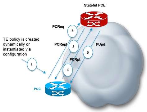
These stages describe how a sample workflow with Stateful PCEP works:
- The PCC is configured to instantiate an SRv6-TE policy. It sends a PCEP Path Computation Request (PCReq) to the PCE, requesting a path by specifying path attributes, optimization objectives, and constraints.
- The PCE stores the request, computes a TE metric shortest-path, and returns the computed SID list in a PCEP Path Computation Reply (PCRepl).
- The PCC allocates a Binding SID (BSID) and activates the SR Policy using the SID list computed by the PCE. The PCC then sends a Path Computation Report (PCRpt) to the PCE, delegating the SR Policy to the PCE and including the BSID
- PCE updates paths as needed: The PCE updates the paths when required, for example, following a multi-domain topology change that impacts connectivity, ensuring the SR Policy remains optimized
Configure head-end router as a PCEP Path Computation Client
Before you begin
Ensure that the PCC and PCE addresses are routable to allow the TCP connection (for exchanging PCEP messages) to be established between them
Procedure
|
Step 1 |
Enable the SR-TE head-end router as a PCEP client (PCC) with 2 PCEP servers (PCE) with different precedence values. Example: |
||
|
Step 2 |
Enable PCEP reporting for all policies in the node. Example: |
||
|
Step 3 |
Set the maximum SID Depth (MSD). Example: |
||
|
Step 4 |
Enable SR-TE related syslogs. Example: |
||
|
Step 5 |
Use the show running-config command to review the current configuration. Example: |
||
|
Step 6 |
Verify the status and summary of IPv6 PCEP peers for SRv6-TE) on the router. Example: |
||
|
Step 7 |
(optional) Enable ECMP-aware path computation for TE metric to customize the SR-TE path calculation. Example:Example:
|
What to do next
-
(optinal) Configure PCEP Authentication
-
(optinal) Configure PCEP-Related Timers
-
(optinal) Configure PCEP Redundancy Type
 Feedback