SRv6 Micro-segment (uSID) Overview

Micro-segments offers a simplified approach to network segmentation. ​By leveraging the principles of Segment Identifiers (SIDs) and the network programming model of SRv6, micro-segments enable greater flexibility and scalability in modern networks.

This chapter explains the functionality of uSIDs, highlighting how they enhance the efficiency of SRv6 routing while reducing header overhead. ​ It also explores their key benefits, limitations, and provides guidance for their implementation and configuration.


Note


This chapter refers to SRv6 micro-segment as uSID.


SRv6 micro-segments

An SRv6 micro-segment (uSID) is an extension of the SRv6 architecture that:

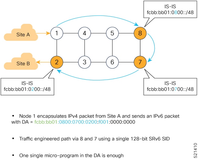
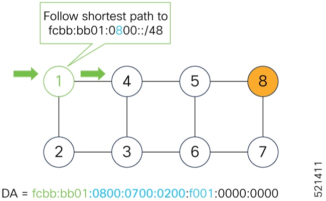
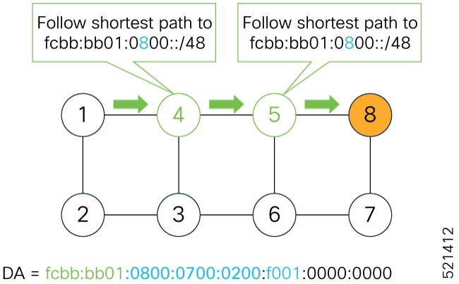
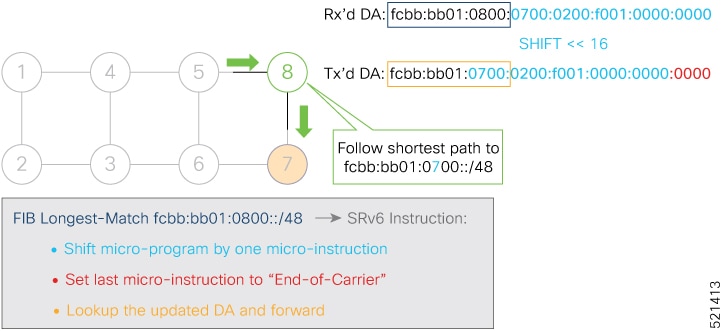
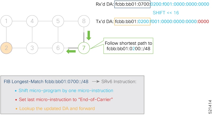
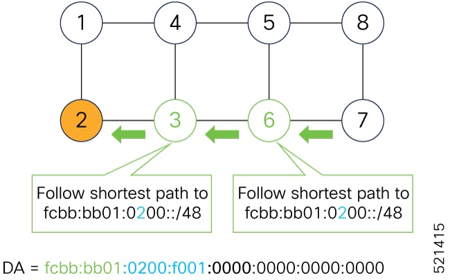
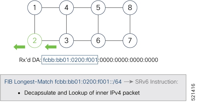
  • encodes up to six SRv6 segment (SID) instructions within a single 128-bit SID address, known as a uSID Carrier.

  • leverages the existing SRv6 network programming architecture without changing the SRv6 data plane or control plane, and

  • provides low MTU overhead and supports efficient hardware operation.

MTU overhead refers to the extra data, such as headers, metadata, or encapsulation, added to a packet on top of the actual payload. Low MTU overhead means the additional data is kept minimal to maximize the usable payload size within the MTU.

For more information about SRv6 uSID, see Network Programming extension: SRv6 uSID instruction and Compressed SRv6 Segment List Encoding in SRH .

Table 1. Feature History Table

Feature Name

Release Information

Feature Description

SRv6 Micro-Segment (uSID)

Release 25.2.1

Introduced in this release on: Centralized Systems (8400 [ASIC: K100]) (select variants only*)

*This feature is now supported on the Cisco 8404-SYS-D routers.

SRv6 Micro-Segment (uSID)

Release 25.1.1

Introduced in this release on: Fixed Systems ( 8700 [ASIC: K100 ] , 8010 [ASIC: A100 ] )

This feature is now supported on:

  • 8712-MOD-M

  • 8011-4G24Y4H-I

SRv6 Micro-Segment (uSID)

Release 7.3.1

This feature is an extension of the SRv6 architecture. It leverages the existing SRv6 Network Programming architecture to encode up to six SRv6 Micro-SID (uSID) instructions within a single 128-bit SID address. Such a SID address is called a uSID Carrier.

In addition, this feature leverages the existing SRv6 data plane and control plane with no changes. It also provides low MTU overhead. For example, if there are 6 uSIDs per uSID carrier, this configuration results in 18 source-routing waypoints using only 40 bytes of overhead (in SRH).

Key concepts of SRv6 uSID

The table summarizes the key concepts and roles within the SRv6 network programming framework.

Table 2. Understanding the key concepts of SRv6 uSID

Term

Description

uSID

An identifier that specifies a micro-segment.

A uSID is linked to a specific behavior, which corresponds to the SRv6 function, such as a Node SID or an Adjacency SID, associated with the given identifier.

The node where a uSID is instantiated is referred to as the "Parent" node.

uSID carrier

A 128-bit IPv6 address (carried in either in the packet destination address or in the SRH) in this format.

<uSID-Block><Active-uSID><Next-uSID>...
<Last-uSID><End-of-Carrier>...
<End-of-Carrier>

The uSID carrier format specifies the type of uSID carrier supported in an SRv6 network. The format specification includes block size and ID size.

The uSID carrier format is specified using the notation "Fbbuu" , where “bb” is size of block and “uu” is the size of the ID.

uSID block

The uSID block is an IPv6 prefix that defines a block of SRv6 uSIDs. This can be an IPv6 prefix allocated to the provider (for example, /22, /24, and so on), or it can be any well-known IPv6 address block generally available for private use, such as the ULA space FC/8, as defined in IETF draft RFC4193.

An SRv6 network may support more than a single uSID block.

The length of block [prefix] is defined in bits. From a hardware-friendliness perspective, it is expected to use sizes on byte boundaries (16, 24, 32, and so on).

uSID ID

The length of the uSID ID is defined in bits. From a hardware-friendliness perspective, it is expected to use sizes on byte boundaries (8, 16, 24, 32, and so on).

Active uSID

The first uSID that follows the uSID block is called the Active uSID.

Next uSID

The next uSID after the Active uSID is called the Next uSID.

Last uSID

The last uSID in the carrier before the End-of-Carrier uSID is called the Last uSID.

End-of-Carrier

A globally reserved uSID that marks the end of a uSID carrier. The End-of-Carrier ID is 0000. All empty uSID carrier positions must be filled with the End-of-Carrier ID; therefore, a uSID carrier can have more than one End-of-Carrier.

Structure of micro-sid carriers in SRH

This example shows an SRH with three micro-SID carriers, which can carry up to 18 micro-instructions.

Micro-SID Carrier1: {uInstruction1, uInstruction2… uInstruction6}

Micro-SID Carrier2: {uInstruction7, uInstruction8… uInstruction12}

Micro-SID Carrier3: {uInstruction13, uInstruction14… uInstruction18}

This illustration represents the structure of an SRH containing three micro-SID or segment identifier carriers. Each Micro-SID carrier acts as a container for a set of micro-instructions, with a maximum capacity of 6 micro-instructions per carrier. These micro-instructions are sequentially organized across the carriers.

  • Micro-SID Carrier 1 contains the first 6 micro-instructions (uInstruction1 to uInstruction6).

  • Micro-SID Carrier 2 contains the next set of 6 micro-instructions (uInstruction7 to uInstruction12).

  • Micro-SID Carrier 3 contains the final 6 micro-instructions (uInstruction13 to uInstruction18).

This structure allows up to 18 micro-instructions to be stored and processed efficiently within the SRH. Organizing the instructions into manageable groups makes interpretation and execution easier.

Benefits of uSID

SRv6 uSID enhances the SRv6 framework by providing improved compatibility, scalability, efficiency, hardware efficency, and ease of deployment. Key benefits include:

Compatibility with SRv6 Framework

  • Leverages the existing SRv6 network programming model without requiring changes. SRv6 uSID is a new pseudo code in the existing SRv6 network programming framework.

  • Leverages the SRv6 data plane (SRH) with no change without any modifications, allowing any SID in the destination address or SRH to act as an SRv6 uSID carrier.

  • Leverages the SRv6 control plane without any modifications.

Scalability

  • Supports a highly scalable number of globally unique nodes within the domain. For instance:

    • 16-bit uSID ID size: 65k uSIDs per domain block

    • 32-bit uSID ID size: 4.3M uSIDs per domain block

  • Enables scalable control plane through summarization at area or domain boundaries, allowing significant scaling without routing extensions.

Efficiency

SRv6 uSID achieves the lowest MTU overhead by supporting 6 uSIDs per uSID carrier, enabling efficient routing.

For example, it supports up to 18 source-routing waypoints with only 40 bytes of overhead.

  • + H.Encaps.Red with an SRH of 40 bytes (8 fixed + 2 * 16 bytes). This capability is available starting from Cisco IOS XR Release 24.3.1.

  • + 6 uSIDs in DA and 12 in SRH

Hardware efficency

  • Leverages hardware capabilities, such as inline IP Destination Address editing and IP Destination Address longest match, to ensure seamless performance.

  • Eliminates the need for additional lookups in indexed mapping tables, enhancing processing speed.

  • Operates with legacy IP-in-IP encapsulation behavior for micro-programs with 6 or fewer uSIDs, simplifying hardware requirements.

Seamless deployment

  • Allows a uSID to function as a SID, with the carrier holding a single uSID.

  • Keeps the inner structure of an SR Policy opaque to the source.

  • A carrier with uSIDs is just seen as a SID by the policy headend Security.

Security

  • Leverages SRv6's native SR domain security.

Limitations for uSID

Ensure that you follow these limitations when working with SRv6 uSID behaviors:

Supported SRv6 uSID endpoint behaviors

The SRv6 network programming is extended with new types of SRv6 SID endpoint behaviors:

  • uN—uN is the short notation for the NEXT-CSID (Compressed SID) End behavior with a pseudocode of shift-and-lookup, and PSP/USD flavors.

  • uA—uA is the short notation for the NEXT-CSID End.X behavior with a pseudocode of shift-and-xconnect, and PSP/USD flavors.

  • uDT—uDT is the short notation for the NEXT-CSID End.DT behavior with the same pseudocode as End.DT4/End.DT6/End.DT46/End.DT2U/End.DT2M.

    Starting from Cisco IOS XR Release 7.5.3, End.DT46 endpoint is supported.

  • uDX—uDX is the short notation for the NEXT-CSID End.DX behavior with the same pseudocode as End.DX4/End.DX6/End.DX2.

Supported SRv6 uSID headend behaviors

  • H.Encap.Red (1 uSID carrier with up to 6 uSIDs)

  • H.Insert.Red : Starting from IOS XR Release 24.3.1, H.Insert.Red is supported only on Cisco Silicon One P100-based routers.

Limitations for encapsulation capabilities and Parameters

Ensure that you adhere to these requirements when configuring IPv6 header fields for SRv6 encapsulated packets.

  • Source address: Supports a single source address (SA) for SRv6 encapsulated packets. This source address is derived from the SRv6 global configuration or, if not configured, from the IPv6 Loopback address.

  • Hop limit:

    • Do not manually configure the hop-limit value in the outer IPv6 header, as this action is not supported.

    • Overlay encapsulation does not propagate the hop limit by default. Use the hop-limit propagate command to enable propagation from the inner header to the outer header.

    • Underlay encapsulation (TI-LFA) behavior is always in propagate mode, regardless of the CLI.

  • Traffic-class:

    • By default, traffic-class propagation is disabled for overlay encapsulation unless you enable it with the traffic-class propagate command, which allows propagation from the inner header to the outer header.

    • Manual configuration of the traffic-class value in the outer IPv6 header is not supported.

    • Underlay encapsulation (TI-LFA) always uses propagate mode, regardless of the CLI configuration.

  • Flow Label:

    • Cisco 8000 series routers use the flow-label from the incoming IPv6 header. During USD operations, flow-label is used from the inner IPv6 header.

    • During H.Encap.Red operations, if the inner packet has a flow label (non-zero value), the Cisco 8000 series routers propagate it to the outer IPv6 header. If the flow label is not present (zero), it is computed.

  • Underlay H-Encapsulation (P Role): A maximum of 6 SIDs (Segment Identifiers) per carrier is used for SRH underlay encapsulation. This applies to P devices responsible for maintaining the underlay transport.

  • Underlay H-Insertion (PE Role):A maximum of 3 SIDs (1 carrier with 3 SIDs per carrier) is used for SRH underlay insertion. This applies to PE devices integrating underlay routing.

  • Overlay H-Encapsulation (PE Role): A maximum of 3 SIDs (1 carrier with 3 SIDs per carrier) is used for SRH overlay encapsulation. This applies to PE devices managing overlay routing.

SRv6 uSID allocation within a uSID block

The SRv6 uSID allocation within a uSID block is a mechanism that

  • involves the assignment of micro-segment identifiers (uSIDs) from a defined IPv6 prefix block and

  • supports both global and local ID allocation for diverse routing and service requirements.

Table 3. Feature History Table

Feature Name

Release

Description

Wide LIB uSID Allocation for End.DT46 SRv6 SIDs

Release 25.1.1

Introduced in this release on: Fixed Systems ( 8010 [ASIC: A100])

This feature is now supported on:

  • 8011-4G24Y4H-I

Wide LIB uSID Allocation for End.DT46 SRv6 SIDs

Release 24.4.1

Introduced in this release on: Fixed Systems (8700 [ASIC: K100]) (select variants only*)

* This feature support is now extended to the Cisco 8712-MOD-M routers.

Wide LIB uSID Allocation for End.DT46 SRv6 SIDs

Release 7.5.3

This feature introduces support for Wide Local ID block (W-LIB).

W-LIB provides an extended set of IDs available for local uSID allocation that can be used when a PE with large-scale Pseudowire termination requires more local uSIDs than provided from the LIB.

W-LIB uSID allocation is supported for End.DT46 SRv6 SIDs.

uSID allocation blocks

In the Segment Routing (SR) domain, uSID allocation is categorized into three types of ID blocks. Each serves a specific purpose and is defined by its scope and behavior.

  • Global ID Block (GIB)

  • Local ID Block (LIB)

  • Wide Local ID Block (W-LIB)

Table 4. Comparison of uSID allocation blocks

Attributes

Global ID Block (GIB)

Local ID Block (LIB)

Wide LIB (W-LIB)

Description

Set of IDs for globally scoped uSID allocation, providing reachability to a node and identifying shortest paths

Set of IDs for locally scoped uSID allocation, tied to local (endpoint) behavior, not independently routable.

Extended set of IDs for local uSID allocation, supporting nodes with large-scale requirements

Key Characteristics

Provides shortest path to a node in the SR domain.

Advertised via an IP route (e.g., /48).

Parent node executes a variant of END behavior.

Supports Anycast uSIDs.

Must be preceded by a globally scoped uSID.

Identifies a local micro-instruction (e.g., cross-connect or VPN context).

Not routable.

Same locally scoped uSID can differ between nodes

Provides more local uSIDs than the standard LIB.

Useful for nodes with large-scale Pseudowire termination

Examples

Nodal uSID (uN) is a globally scoped behavior.

Multiple nodes may share the same globally scoped uSID for Anycast.

Locally scoped uSID L may bind two different behaviors on nodes N1 and N2.

Used for local endpoint-specific actions.

A PE node that requires more local uSIDs for extensive Pseudowire termination.

uSID allocation example

This section explains how locally scoped and globally scoped uSIDs are allocated, provides an example with a specific uSID Locator Block, and illustrates the allocation scheme. We also explore how global and local uSIDs are assigned for a node within an SRv6 domain.

The request to allocate locally scoped uSIDs comes from SRv6 clients (such as IS-IS or BGP). The request can be to allocate any available ID (dynamic allocation) or to allocate a specific ID (explicit allocation).

  • uSID Allocation request source: The request to allocate locally scoped uSIDs comes from SRv6 clients (such as IS-IS or BGP). The request can be to allocate any available ID (dynamic allocation) or to allocate a specific ID (explicit allocation).

  • Example parameters for uSID Allocation:

    • uSID Locator Block length: 32 bits

    • uSID Locator Block: FCBB:BB00::/32 (with B being a nibble value picked by operator)

    • uSID length (Locator Node ID / Function ID): 16 bits

    • uSID: FCBB:BB00:XYWZ::/48 (with XYWZ being variable nibbles)

  • Allocation Scheme: A uSID FCBB:BB00:XYWZ::/48 is said to be allocated from its block (FCBB:BB00::/32). A uSID is allocated from the GIB or LIB of block FCBB:BB00::/32 depending on the value of the "X" nibble:

    • GIB: nibble X from hex(0) to hex(D)

    • LIB: nibble X hex(E) or hex(F)

    Figure 1. Allocation Scheme

    With this allocation scheme, the uSID block FCBB:BB00::/32 supports up to 57343 global uSIDs (routers) with each router supporting up to 8192 local uSIDs.

    For example, this image depicts the global uSIDs allocated for 3 nodes within the SRv6 domain.

    Figure 2. Global uSIDs allocated for 3 nodes

    Examining R1 in more detail, this node has Local uSIDs that are associated with uA end-point behaviors as follows:

    • Function ID 0xE000 – cross-connect to L3 neighbor R2

    • Function ID 0xE001 – cross-connect to L3 neighbor R3

    The underlay uSIDs present on R1 are:

    • FCBB:BB00:0001::/48

    • FCBB:BB00:0001:E000::/64

    • FCBB:BB00:0001:E001::/64

Limitations for uSID allocation

Cisco IOS XR supports uSID allocation using GIB, LIB, and W-LIB. The supported features, ID ranges, and endpoint behaviors depend on the software release version.

Supported GIB and LIB features and ranges in Cisco IOS XR Release 7.5.3 and later

New functionalities added:

  • Configurable explicit LIB range.

  • Assignment of explicit LIB for user-assigned IDs of local segments.

  • Manual uDT46 allocation from explicit LIB.

  • Support for Wide LIB (W-LIB)

  • Configurable explicit W-LIB range

  • Explicit W-LIB allocation for user-assigned IDs of local segments.

  • Manual uDT46 from explicit W-LIB

These are the supported range of IDs:

  • GIB: The range of IDs in the GIB is 0x000 to 0xDFFF.

  • LIB: The range of IDs by default in the LIB is divided into:

    • Dynamic: 0xE000 to 0xFDFF

    • Explicit: 0xFE00 to 0xFEFF

    • Reserved: 0xFF00 to 0xFFEF and 0xFFF8 to 0xFFFF

  • W-LIB: The range of IDs by default in the W-LIB is divided into:

    • Reserved: 0xFFF0 to 0xFFF6

    • Explicit: 0xFFF7

Figure 3. GIB/LIB/W-LIB

Supported GIB and LIB features and ranges in Cisco IOS XR Release 7.5.2 and earlier

New functionalities added:

  • GIB for user-assigned IDs of global segments (uNs)

  • LIB for dynamically assigned IDs of local segments, including:

    • uA end-point behavior

    • Service de-multiplexing end-point behaviors (for example, End.DT, End.DX, End.DX2)

The range of IDs supported by the Cisco IOS XR 7.5.2 and earlier implementation are as follows:

  • The range of IDs in the GIB is 0x000 to 0xDFFF.

  • The range of IDs by default in the LIB is divided as follows:

    • Dynamic: 0xE000 to 0xFDFF

    • Reserved: 0xFE00 to 0xFFFF

Figure 4. GIB/LIB

uSID allocation recommendations

We recommend allocating uSIDs from the private IPv6 space (IPv6 Unique Local Address [ULA] range). These addresses are not routable outside the domain and are therefore secure. Allocation from the public IPv6 space (Global Unicast Addresses [GUA] range) is also possible but not recommended.

For example:

  • Use a /24 subnet from FC::/8 ULA.

  • SRv6 Base Block = FCBB:BB::/24, with B indicating a nibble value picked by operator.

  • SRv6 uSID Block = FCBB:BBVV/32, with VV indicating a nibble value picked by the operator.

    • 256 /32 uSID blocks possible from this allocation, from block 0 (FCBB:BB00/32) to block 255(FCBB:BBFF/32)

    • A network slice is assigned a /32 uSID block:

      • FCBB:BB00/32 for min-cost slice (shortest path based on minimum IS-IS cost)

      • FCBB:BB08/32 for min-delay slice (shortest path based on minimum latency using Flex Algo instance 128)

How SRv6 uSIDs are allocated

The process describes how SRv6 uSID-based VPN and traffic engineering operate to enable traffic forwarding between two VPNv4 sites (Site A and Site B) over an SRv6 domain with a traffic-engineered path.

Summary

The key components involved in the process are:

  • Ingress PE node (Node 1): Encapsulates IPv4 packets from Site A into IPv6 packets with SRv6 uSID instructions

  • Egress PE node (Node 2): Decapsulates IPv6 packets and performs IPv4 table lookup to deliver packets to Site B.

  • SRv6 capable nodes (Nodes 8 and 7): Execute SRv6 uSID-based instructions to forward packets along the traffic-engineered path. The nodes are configured with 32-bit SRv6 block = fcbb:bb01 and 16-bit SRv6 ID.

    For example:

    • Node 7 uN = fcbb:bb01:0700::/48

    • Node 8 uN = fcbb:bb01:0800::/48

  • Classic IPv6 nodes (Nodes 3, 4, 5, and 6): Forward packets using standard IPv6 shortest-path forwarding without modifying the outer destination address (DA).

These IGP routes are advertised:

  • Node 8 advertises the IGP route fcbb:bb01:0800::/48

  • Node 7 advertises the IGP route fcbb:bb01:0700::/48

  • Node 2 advertises the IGP route fcbb:bb01:0200::/48

Workflow

Figure 5. Integrated VPN and traffic engineering SRv6 uSID usecase

These stages describe the process of SRv6 uSID allocation:

  1. Packet Encapsulation (Node 1 – Ingress PE):

    • Node 1 receives an IPv4 packet from VPNv4 Site A.

    • Encapsulates the IPv4 packet into an IPv6 packet with the destination address set to fcbb:bb01:0800:0700:0200:f001:0000:0000.

      This is a uSID carrier, with a list of micro-instructions (uSIDs) (0800, 0700, 0200, f001, and 0000 – indicating the end of the instruction).

      uSIDs (uNs) 0800, 0700, 0200 are used to realize the traffic engineering path to Node 2 with way points at Nodes 8 and 7. uSID f001 is the BGP-signalled instruction (uDT4) advertized by Node 2 for the VPNv4 service

    Figure 6. Node 1: End.B6.Encaps Behavior
  2. Packet forwarding through classic IPv6 nodes (Nodes 4 and 5): Nodes 4 and 5 simply forward the packet along the shortest path to Node 8, providing seamless deployment through classic IPv6 nodes.

    Figure 7. Node 4 and Node 5: Classic IPv6 Nodes
  3. Processing at Node 8 (SRv6 uN behavior): When Node 8 receives the packet, it performs SRv6 uN behavior (shift-and-lookup with PSP/USD). It removes its outer DA (0800) and advances the micro program to the next micro instruction by performs these actions:

    1. Pops its own uSID (0800)

    2. Shifts the remaining DA by 16-bits to the left

    3. Fills the remaining bits with 0000 (End-of-Carrier)

    4. Performs a lookup for the shortest path to the next DA (fcbb:bb01:0700::/48)

    5. Forwards it using the new DA fcbb:bb01:0700:0200:f001:0000:0000:0000

    Figure 8. Node 8: SRv6 uN Behavior (Shift and Forward)
  4. Processing at Node 7 (SRv6 uN behavior): When Node 7 receives the packet, it performs the same SRv6 uN behavior (shift-and-lookup with PSP/USD), forwarding it using the new DA fcbb:bb01:0200:f001:0000:0000:0000:0000

    Figure 9. Node 7: SRv6 uN Behavior (Shift and Forward)
  5. Packet forwarding through classic IPv6 nodes (Nodes 6 and 3): Nodes 6 and 3 simply forward the packet along the shortest path to Node 2, providing seamless deployment through classic IPv6 nodes.

    Figure 10. Node 6 and Node 3: Classic IPv6 Nodes
  6. Packet decapsulation (Node 2 – Egress PE): When Node 2 receives the packet, it performs an SRv6 uDT4 behavior (End.DT4—Endpoint with decapsulation and IPv4 table lookup) to VPNv4 Site B.

    Figure 11. Node 2: SRv6 uDT4 Behavior

Configure SRv6

To enable SRv6 functionality on your network, extending IS-IS to support SRv6 capabilities and SIDs.

Procedure


Step 1

Configure SRv6 locators.

Step 2

(Optional) Configure algorithm associated with locator.

Step 3

Enable SRv6 under IS-IS.

Step 4

Enable SRv6 Services under BGP.

Step 5

Verify SRv6 manager.

Example:

This example shows how to verify the overall SRv6 state from SRv6 Manager point of view. The output displays parameters in use, summary information, and platform specific capabilities.

Router# SF-D#sh segment-routing srv6 manager 
Parameters:
  SRv6 Enabled: No
  SRv6 Operational Mode: None
  Encapsulation:
    Source Address:
      Configured: ::
      Default: 77::77
    Hop-Limit: Default
    Traffic-class: Default
    SID Formats:
      f3216 <32B/16NFA> (2)
    uSID LIB Range:
    LIB Start : 0xe000
    ELIB Start : 0xfe00
    uSID WLIB Range:
    EWLIB Start : 0xfff7
Summary:
  Number of Locators: 0 (0 operational)
  Number of SIDs: 0 (0 stale)
  Max SID resources: 24000
  Number of free SID resources: 24000
  OOR:
    Thresholds (resources): Green 1200, Warning 720
    Status: Resource Available
      History: (0 cleared, 0 warnings, 0 full)
Platform Capabilities:
  SRv6: Yes
  TILFA: Yes
  Microloop-Avoidance: Yes
  Endpoint behaviors:
    End.DT6
    End.DT4
    End.DT46
    End (PSP/USD)
    End.X (PSP/USD)
    uN (PSP/USD)
    uA (PSP/USD)
    uDT6
    uDT4
    uDT46
Headend behaviors:
  H.Insert.Red
  H.Encaps.Red
Security rules:
  SEC-1
  SEC-2
  SEC-3
Counters:
  None
Signaled parameters:
  Max-SL : 3
  Max-End-Pop-SRH : 3
  Max-H-Insert : 0 sids
  Max-H-Encap : 2 sids
  Max-End-D : 5
Configurable parameters (under srv6):
  Ranges:
   LIB : Yes
   WLIB : Yes
  Encapsulation:
    Source Address: Yes
    Hop-Limit : value=No, propagate=Yes
    Traffic-class : value=No, propagate=Yes
    Default parameters (under srv6):
  Encapsulation:
    Hop-Limit : value=128, propagate=No
    Traffic-class : value=0, propagate=No
    Max Locators: 16
    Max SIDs: 24000
    SID Holdtime: 3 mins
Router# :SF-D#

Step 6

Verify the allocation of SRv6 local SIDs off locator(s).

Example:

Router# show segment-routing srv6 locator myLoc1 sid
SID                         Behavior          Context                           Owner               State  RW
--------------------------  ----------------  ------------------------------    ------------------  -----  --
2001:0:8::                  uN (PSP/USD)      'default':1                       sidmgr              InUse  Y

Step 7

Display detail information regarding an allocated SRv6 local SID.

Example:

Router# show segment-routing srv6 locator myLoc1 sid 2001:0:8:: detail
SID                         Behavior          Context                           Owner               State  RW
--------------------------  ----------------  ------------------------------    ------------------  -----  --
2001:0:8::                  uN (PSP/USD)      'default':8                       sidmgr              InUse  Y
  SID Function: 0x8
  SID context: { table-id=0xe0800000 ('default':IPv6/Unicast), opaque-id=8 }
  Locator: 'myLoc1'
  Allocation type: Dynamic
  Created: Dec 10 22:10:51.596 (02:10:05 ago)

SRv6 uSID features

This table categorizes key SRv6 features and functionalities into the underlay and the overlay.

  • Underlay: Represents the foundational network infrastructure responsible for basic IP reachability, routing, and transport mechanisms that enable segment routing. It includes elements such as SRv6 locators, flexible algorithms, and protocols that ensure efficient path computation and traffic engineering at the network core. Additionally, the underlay supports performance monitoring capabilities that measure network health and transport metrics such as latency, loss, and liveness to ensure reliable and resilient connectivity.

  • Overlay: Builds upon the underlay to provide advanced services and programmability, including VPN services, service chaining, and application-specific traffic steering. It leverages the underlay’s capabilities to deliver scalable, flexible, and programmable network services that meet modern operational requirements such as network slicing and service assurance. The overlay also benefits from unified visibility and assurance tools that correlate overlay service performance with underlay metrics, enabling comprehensive monitoring and SLA compliance.

This segregation helps clarify the roles and interactions of various SRv6 components, facilitating better network design, deployment, and management by distinguishing between transport infrastructure and service-level programmability.

Table 5.

Supported uSID features

Description

Underlay

SRv6 Locators

SRv6 locators are fundamental IPv6 address prefixes that define the address space for Segment Identifiers (SIDs) within an SRv6 network. They are crucial for enabling efficient routing and precise traffic steering.

Implementing SRv6 Flexible Algorithms

SRv6 flexible algorithms (Flex-Algo) empower network operators to define routing behaviors tailored to specific operational requirements. Flex-Algo enables precise path computation beyond traditional shortest-path routing, allowing for customized traffic engineering, network slicing, and transport SLA assurance.

Path Computation Element Protocol

Path Computation Element Protocol (PCEP) facilitates centralized management and dynamic optimization of SR paths. PCEP enables Path Computation Clients (PCCs) to communicate with Path Computation Elements (PCEs) for path computation, delegation, and real-time adjustments. It is used to enhance network efficiency, flexibility, and resilience by supporting advanced traffic engineering constraints and ensuring secure control plane communications.

Traffic Engineering in IPv6 Networks Using SRv6-TE

Segment Routing over IPv6 traffic engineering (SRv6-TE) provides granular control and flexibility in managing network traffic. SRv6-TE enables administrators to steer traffic across IPv6 networks according to specific policies and requirements, facilitating explicit path creation for applications demanding particular QoS levels. It is used to enhance scalability, reduce complexity, optimize resource utilization, and integrate seamlessly with existing IPv6 infrastructure.

SRv6-MPLS L3 Service Interworking Gateways

When bridging SRv6 and MPLS domains, the SRv6 side will often use uSIDs for its service and transport SIDs. The interworking gateway needs to correctly interpret and translate these uSIDs to their MPLS equivalents or other SRv6 formats.

Overlay

SRv6 Layer 3 VPN Services and Global Routing

SRv6 enables scalable, flexible, and programmable Layer 3 VPN (L3VPN) and global routing services, which are essential for modern network traffic engineering and service delivery.

Advanced SRv6 Layer 3 features

Advanced SRv6 Layer 3 features provide the agility and efficiency required by modern networks. Specialized mechanisms offer advanced functionalities to optimize resource utilization and streamline traffic management across complex network segments. These capabilities are used to enhance network visibility and diagnostics, supporting adaptable, resilient, and future-proof deployments.

SRv6-Based Layer 2 and Integrated VPN Services

SRv6-based Layer 2 and integrated VPN services provide flexible, scalable, and resilient solutions for modern network demands.

Monitoring

SRv6 Network Performance Measurement

Tools like liveness monitoring, delay measurement, and path tracing operate by sending probes along SRv6 paths. If these paths are constructed using uSIDs, the performance measurement mechanisms must be designed to correctly interpret and traverse these uSID-based paths to gather accurate metrics.

SRv6 Traffic Accounting

Traffic accounting tracks data flow over SRv6 paths. If the network utilizes uSIDs for its segment routing, the accounting system needs to correctly attribute traffic to these uSIDs and their associated locators to provide granular insights into resource consumption and traffic patterns.