Segment Routing over IPv6 Traffic Engineering (SRv6-TE)
Segment Routing over IPv6 Traffic Engineering (SRv6-TE ) is a traffic engineering solution that
-
enables you to steer traffic across a network based on specific policies and requirements and provides greater control over how traffic flows through the network
-
allows you to create explicit paths through the network for specific traffic flows where a particular application or service requires a specific quality of service (QoS) level, such as low latency or high bandwidth, and
-
leverages the concept of source routing, where the source node determines the path and encodes it in the packet header as a list of segments. This list of segments is added to an IPv6 routing header called the SRv6 Segment Routing Header (SRH) in the incoming packet.
|
Feature Name |
Release Information |
Feature Description |
|---|---|---|
|
SRv6 Traffic Engineering |
Release 25.4.1 |
Introduced in this release on: Fixed Systems (8700 [ASIC: K100])(select variants only*) *This feature is supported on Cisco 8711-48Z-M routers. |
|
SRv6 Traffic Engineering |
Release 25.1.1 |
Introduced in this release on: Fixed Systems (8010 [ASIC: A100])(select variants only*) *This feature is supported on Cisco 8011-4G24Y4H-I routers. |
|
SRv6 Traffic Engineering |
Release 24.4.1 |
Introduced in this release on: Fixed Systems(8200, 8700);Modular Systems (8800 [LC ASIC: P100]) (select variants only*) *This feature is now supported on:
|
|
SRv6 Traffic Engineering |
Release 7.10.1 |
You can now control the traffic flows within the network by defining the explicit and dynamic paths for traffic flows using the Segment Identifier (SID) within the IPv6 packet header. Defining explicit and dynamic paths based on different attributes and constraints allow the router to optimize routing decisions and enhance resource utilization. SRv6-TE policies supports the following functionalities:
This feature introduces the following changes: CLI: YANG Data Model:
(see GitHub, YANG Data Models Navigator) |
Why SRv6-TE is Essential for Modern Networks
SRv6-TE provides enhanced control and flexibility in steering traffic across a network based on specific policies and requirements. This solution eliminates the need for intermediate nodes to maintain per-application and per-flow state. Only the head-end nodes at the network edge maintain state, while the remaining nodes forward packets based on instructions encoded in the packet header. This source routing approach improves scalability and reduces complexity.
Key benefits of SRv6-TE include:
-
Explicit traffic steering: Enables the creation of explicit paths for traffic flows that require specific Quality of Service (QoS) levels, such as low latency or high bandwidth.
-
Source routing efficiency: The source node calculates and encodes the path directly in the packet header, which offloads path computation from intermediate routers.
-
Optimized resource utilization: Utilizes network bandwidth more effectively than traditional MPLS RSVP-TE by leveraging Equal-Cost Multi-Path (ECMP) within each segment.
-
Simplified network management: Embeds forwarding paths within packets, which reduces overhead and makes the network more responsive to changes.
-
Support for advanced traffic engineering: Supports flexible algorithms and policies for intents like low latency, disjointness, affinity inclusion/exclusion, and Shared Risk Link Group (SRLG) exclusion, often with Path Computation Element (PCE) assistance.
-
Seamless IPv6 integration: Leverages existing IPv6 infrastructure for easier deployment.
Comparison between SRv6-TE and MPLS RSVP-TE
|
Feature |
SRv6-TE |
Traditional MPLS RSVP-TE |
|---|---|---|
|
State Maintenance |
Only head-end nodes maintain state |
All nodes along the path maintain per-flow state |
|
Routing Paradigm |
Source routing with path encoded in packet header. |
Signaling-based path setup with RSVP protocol. |
|
Bandwidth Utilization |
More efficient via ECMP within segments |
Less efficient, limited ECMP usage |
|
Traffic Engineering Flexibility |
Supports advanced policies including flexible algorithms and explicit paths. |
Supports explicit paths but with more overhead. |
|
Integration |
Native IPv6-based, leverages IPv6 infrastructure |
MPLS-based, requires MPLS infrastructure |
Methods of traffic engineering with SRv6
Traffic engineering over SRv6 can be accomplished in these ways:
-
End-to-End Flexible Algorithm: This is used for traffic engineering intents achieved with Flexible Algorithm, including low latency, multi-plane disjointness, affinity inclusion/exclusion, and SRLG exclusion. See .
-
SRv6-TE Policy: This is used for traffic engineering intents beyond Flex Algo capabilities, such as path disjointness that rely on path computation by a PCE. In addition, this is used for user-configured explicit paths. .
SRv6-TE Policy
An SRv6-TE policy is a traffic engineering mechanism that
-
defines specific end-to-end paths using lists of micro-segment IDs (uSIDs)
-
enables you to steer packets along chosen routes instead of default IGP paths, and
-
is uniquely identified by its head-end, color, and end-point attributes.
Components of SRv6-TE policy
An SRv6-TE policy is uniquely identified by an ordered list of three components:
-
Head-end: The node where the SRv6-TE policy is instantiated.
-
Color: A numerical value that distinguishes between multiple policies configured for the same node pair (Head-end and End-point). Every policy between the same node pairs requires a unique color value.
-
End-point: The destination of the SRv6-TE policy.
Every SRv6-TE policy has a color value. Every policy between the same node pairs requires a unique color value. An SRv6-TE policy uses one or more candidate paths.
Each SRv6-TE policy utilizes one or more candidate paths. A candidate path can consist of a single SID-list or a set of weighted SID-lists for Weighted Equal-Cost Multi-Path (WECMP). A SID list can be dynamically computed by a Path Computation Element (PCE) or explicitly configured by a user. For more information, see SRv6-TE Policy Path Types.Candidate paths
The candidate path is a category of routing path that
-
consists of a single segment list or a set of weighted SID-lists
-
serves as one of the multiple possible routes within an SR Policy, and
-
enables load sharing and failover by allowing traffic to be distributed or switched among the SID-lists.
Characteristics of candidate path
A candidate path has these characteristics:
-
It has a preference – If two policies have same {color, endpoint} but different preferences, the policy with the highest preference is selected.
-
It is associated with a single Binding SID (uB6) – A uB6 SID conflict occurs when there are different SRv6 policies with the same uB6 SID. In this case, the policy that is installed first gets the uB6 SID and is selected.
-
It is valid if it is usable.
A path is selected when the path is valid and its preference is the best among all candidate paths for that policy. The protocol of the source is not relevant in the path selection logic.
Types of candidate path
An SR Policy manages multiple candidate paths, but only one candidate path is selected and installed in the RIB/FIB as the active path at any time. Candidate paths can be dynamic (computed) or explicit (manually specified), providing flexibility for traffic engineering and network resilience.
Configure SRv6-TE candidate Paths with weighted SID lists
Use this procedure to define SRv6-TE policies that utilize multiple segment lists with assigned weights for weighted load balancing.
Procedure
|
Step 1 |
Set the SRv6 SID format and define the first SRv6 segment list. Example: |
|
Step 2 |
Configure the SRv6-TE policy with candidate paths and weighted SID lists. Example: |
|
Step 3 |
Verify the configuration with show running configuration. Example: |
Explicit Paths
An SRv6 TE explicit path is a traffic engineering route in IPv6 networks that:
-
uses a predefined list of Segment Identifiers (SIDs)
-
determines the precise forwarding path for packets, giving direct control over how traffic moves through the network, and
-
allows segment lists to include uSIDs, uSID carriers, or a mix of both.
Benefits of explicit paths
Explicit paths provide several advantages in traffic engineering:
-
Precise traffic control: You can specify the exact route that packets take, ensuring traffic follows your preferred path through the network.
-
Predictable performance: By defining the path, you avoid unexpected routing changes, leading to consistent and reliable application performance.
-
Enhanced policy enforcement: You can meet specific service requirements—such as low latency, security, or bandwidth guarantees—by choosing the path that best fits your policy.
-
Improved resource utilization: You can balance traffic loads or avoid congested links by selecting less utilized routes, optimizing network efficiency.
-
Deterministic failover: In case of a failure, you can design backup explicit paths, ensuring quick and predictable recovery.
Guidelines for SRv6-TE explicit path
Address Adj-SID preference
When configuring explicit paths using IP addresses of links, consider the SRv6-TE process's Adj-SID preferences.
The SRv6-TE process prefers the protected Adj-SID of the link if one is available. Furthermore, it prefers a manual-protected Adj-SID over a dynamic-protected Adj-SID. You can configure the path to prefer protected or unprotected Adj-SIDs, or to use only protected or unprotected Adj-SIDs, based on your specific network requirements.
Enable Segment List SID validation
Enable SRv6-TE explicit segment list SID validation. This allows the head-end node to validate the SIDs in an explicit SRv6-TE segment list against the SR-TE topology database.
Compose segment lists
Compose segment lists using uSIDs, uSID carriers, or a combination of both.
Configure SRv6-TE policy with explicit path
Procedure
|
Step 1 |
Create a segment list with SRv6 uSIDs. Example: |
|
Step 2 |
Create the SRv6-TE policy. Example: |
|
Step 3 |
View the show run configuration. Example: |
|
Step 4 |
Verify the SR-TE policy configuration. Example: |
SRv6-TE explicit segment list SID validation
SRv6-TE explicit segment list SID validation is a process that evaluates whether an SR policy's candidate path's explicit segment list is valid and therefore usable. The head-end node performs this validation by checking if the specified hops are present in the SR-TE topology database.
Segment list SID validation
When enabled, this validation occurs at two key times:
-
Before programming the SR policy.
-
After an IGP topology change.
If the validation process identifies issues:
-
The segment list is declared invalid if validation fails.
-
An SR policy candidate path is declared invalid if it contains no valid segment lists.
-
An SR policy is declared invalid if it has no valid candidate paths.
Usage Guidelines for SRv6 explicit segment list SID validation
Enable or disable segment list SID validation
Enable segment list SID validation globally for all SRv6 explicit segment lists or for a specific SRv6 segment list. If SIDs in an explicit segment list are expected to not be found in the head-end (for example, in a multi-domain case), you can disable the topology check for that specific segment list.
Distribute SR-TE topology from appropriate sources
Distribute the SR-TE topology from the correct source for accurate path computation. For intra-domain paths, the SR-TE topology should be distributed from an Interior Gateway Protocol (IGP). For multi-domain paths, use BGP-LS for distribution.
Ensure SRv6 segment lists are not empty
Ensure that the SRv6 segment list in an explicit candidate path of an SRv6 policy is not empty. An empty segment list will prevent the policy from steering traffic correctly.
Maintain consistent data plane types within segment lists
Ensure all segments within a segment list share the same data plane type. All segments in a given segment list must consistently be either SRv6 or SR-MPLS.
Validate SIDs against local parameters
All SIDs in a segment list are validated against the local SID block and SID format. Top SID validation occurs by performing path resolution using the top SID. A segment list is also validated against the Maximum Segment Depth (MSD).
Enable SID validation globally for all SRv6 explicit segment lists
Before you begin
Verify if the SR-TE topology is available on the headend PCC router using the show segment-routing traffic-eng topology command.
Procedure
|
Step 1 |
Enable SID validation globally. Example:The following example shows how to enable SID validation globally and disable SID validation for a specific SRv6 explicit segment list: |
|
Step 2 |
Verify the running configuration. Example: |
|
Step 3 |
Verify the SID validation globally for all SRv6 explicit segment lists. Example: |
Dynamic Paths
A dynamic path is a type of SRv6-TE path that
-
is based on an optimization objective and a set of constraints
-
is computed by the head-end to generate a SID-list, and
-
automatically recomputes when the network topology changes.
Optimization objectives for dynamic path computation
An optimization objective defines the primary goal for computing a dynamic path. This objective guides the path computation process to find the most suitable path based on criteria such as minimizing latency, maximizing bandwidth, or finding the shortest path.
Optimization objectives allow the head-end router to compute a uSID-list that expresses the shortest dynamic path according to the selected metric type:
-
Hopcount: Computes the path with the least number of hops.
-
IGP metric: Computes the path based on the Interior Gateway Protocol (IGP) metric. For more information, refer to the Implementing IS-IS and Implementing OSPF chapters in the Routing Configuration Guide for Cisco 8000 Series Routers
-
TE metric: Computes the path based on the Traffic Engineering (TE) metric. See the section for information about configuring TE metrics. See the Configure Interface TE Metrics task.
-
Delay (latency): Computes the path based on link latency. See the chapter for information about measuring delay for links or SRv6 policies.
Constraints for dynamic path computation
Constraints are rules or conditions applied during the path computation process that restrict the possible routes a dynamic path can take. These allow the head-end router to compute a path that adheres to specific network policies or requirements.
-
Affinity: You can apply a color or name to links or interfaces by assigning affinity bit-maps to them. You can then specify an affinity (or relationship) between an SRv6 policy path and link colors. SRv6-TE computes a path that includes or excludes links that have specific colors or combinations of colors. For more information, see the Named Interface Link Admin Groups and SRv6-TE Affinity Maps section.

Note
When performing path computation on a PCE, configuring both affinity and disjoint-path constraints simultaneously is not supported.
-
Disjoint: SRv6-TE computes a path that is disjoint from another path in the same disjoint-group. Disjoint paths do not share network resources. Path disjointness may be required for paths between the same pair of nodes, between different pairs of nodes, or a combination (only same head-end or only same end-point).
-
Segment Protection-Type Behavior: You can control whether protected or unprotected segments are used when encoding the SID-list of an SRv6 policy candidate path. The types of segments that could be used when building a SID-list include uSIDs and adjacency SIDs (uA SID). For details and usage guidelines, see the Segment Protection-Type Constraint section.
Guidelines of SRv6 policy with dynamic path
-
An SRv6-TE policy combines a dynamic path with specific optimization objectives and constraints.
-
If you do not specify a customized per-policy locator and Binding SID (BSID) behavior, the policy uses the global locator and BSID behavior. Similarly, if you do not specify a customized per-policy source address, the policy uses the local IPv6 source address.
-
Disjoint-path and affinity constraints are mutually exclusive and cannot be configured simultaneously.
Configure SRv6 policy with dynamic path
Use this procedure to configure an SRv6-TE policy that uses a dynamic path, including optimization objectives and affinity constraints.
Procedure
|
Step 1 |
Configure an SRv6-TE policy that uses a dynamic path. Example:This example shows a configuration of an SRv6 policy at an SRv6-TE head-end router using the global locator and source address. The policy has a dynamic path with optimization objectives and affinity constraints computed by the SR-PCE. The following example shows a configuration of a manual SRv6 policy at an SRv6-TE head-end router with customized locator and source address. The policy has a dynamic path with optimization objectives and affinity constraints computed by the SR-PCE. |
|
Step 2 |
View the running configuration of SRv6 policy with dynamic path. Example:The following example shows a configuration of an SRv6 policy at an SRv6-TE head-end router using the global locator and source address. The policy has a dynamic path with optimization objectives and affinity constraints computed by the SR-PCE. This example shows a configuration of a manual SRv6 policy at an SRv6-TE head-end router with customized locator and source address. The policy has a dynamic path with optimization objectives and affinity constraints computed by the SR-PCE. |
|
Step 3 |
Verify the SRv6 policy with dynamic path. Example: |
Configure interface TE metrics
Use this procedure to assign a Traffic Engineering (TE) metric to specific interfaces, which influences dynamic path computation in SRv6-TE policies.
Procedure
|
Step 1 |
Use the metric use the metric value command. command to configure the TE metric for the interface. The value range is from 0 to 2147483647. Example: |
|
Step 2 |
Verify the configured TE metrics for the interfaces. Example: |
Named Interface Link Admin Groups and SRv6-TE Affinity Maps
Named interface link admin groups and SRv6-TE affinity maps are SRv6 TE features that
-
provide a simplified and more flexible means of configuring link attributes and path affinities
-
allow the use of descriptive color names instead of hexadecimal numbers for attributes, and
-
enable the definition of granular constraints for SRv6-TE policies.
Traditional TE scheme
In the traditional Traffic Engineering (TE) scheme, links are configured with attribute-flags. These flags are flooded as TE link-state parameters using Interior Gateway Protocols (IGPs), such as Open Shortest Path First (OSPF).
Enhanced configuration with affinity maps
Named interface link admin groups and SRv6-TE affinity maps allow you to assign, or map, up to 32 color names for affinity and attribute-flag attributes. This approach replaces the use of 32-bit hexadecimal numbers, making configurations more intuitive. After these mappings are defined, the attributes can be referred to by their corresponding color name directly in the CLI.
Defining Constraints
Using these affinity maps, you can define constraints with increased flexibility. Constraints can be specified using these arguments, where each statement can contain up to 10 distinct colors.
-
include-all -
include-any -
exclude-any
Configuration scheme coexistence
You can configure affinity constraints using either traditional attribute flags or the Flexible Name Based Policy Constraints scheme. However, if configurations for both schemes exist simultaneously, only the configuration pertaining to the new, name-based scheme is applied to the SRv6-TE policies.
Configure Named Interface Link Admin Groups and SRv6-TE Affinity Maps
Use this procedure to configure Named Interface Link Admin Groups and SRv6-TE Affinity Maps, providing a flexible way to define link attributes and path affinities for SRv6-TE policies.
Procedure
|
Step 1 |
Assign affinity to interfaces on routers with interfaces that have an associated admin group attribute. To assign affinity to interfaces, use the segment-routing traffic-eng interface interface affinity name command . This configuration is applicable to any router (SRv6-TE head-end or transit node) with colored interfaces. Example: |
|
Step 2 |
Define affinity maps. To define the affinity maps, use the segment-routing traffic-eng affinity-map name bit-position bit-position command. The bit-position range is from 0 to 255. Example: |
|
Step 3 |
Verify the show running configuration. Example: |
Segment Protection-Type Constraint
Segment protection-type behavior is a feature that
-
introduces the ability to control whether protected or unprotected segments are used
-
influences the encoding of the SID-list of an SRv6 policy candidate path, and
-
determines whether failures along the path are protected by TI-LFA.
Segment Types
The types of segments that can be used when building a SID-list include uSIDs and adjacency SIDs (uA SIDs).
-
Prefix SID: A global segment that represents a prefix identifying a specific node. A prefix SID is programmed with a backup path computed by the Interior Gateway Protocol (IGP) using Topology-Independent Loop-Free Alternate (TI-LFA).
-
Adjacency SID: A local segment that represents an IGP adjacency. An adjacency SID can be programmed with or without protection. Protected adjacency SIDs are programmed with a link-protectant backup path computed by the IGP (TI-LFA) and are used if the link associated with the IGP adjacency fails.
Prefix SIDs and adjacency SIDs can be leveraged as segments within a SID-list to forward a packet along a path traversing specific nodes and/or over specific interfaces between nodes. The specific type of segment used when encoding the SID-list will determine whether failures along the path would be protected by TI-LFA. This capability allows operators to offer either unprotected or protected services over traffic engineered paths, depending on their service offerings.
Segment protection-type constraint behaviors
These behaviors are available with the segment protection-type constraint:
-
protected-only: The SID-list must be encoded using protected segments.
-
protected-preferred: The SID-list should be encoded using protected segments if available; otherwise, the SID-list may be encoded using unprotected Adj-SIDs. This is the default behavior when no segment protection-type constraint is specified.
-
unprotected-only: The SID-list must be encoded using unprotected Adj-SID.
-
unprotected-preferred: The SID-list should be encoded using unprotected Adj-SID if available, otherwise SID-list may be encoded using protected segments.
Limitations of segment protection-type constraint
-
This constraint applies to candidate-paths of manual SR policies with dynamically computed paths.
-
PCEP has been augmented (vendor-specific object) to allow a PCC to indicate the segment protection-type constraint to the PCE.
-
When the segment protection type constraint is protected-only or unprotected-only, the path computation must adhere to the constraint. If the constraint is not satisfied, the SRv6 policy will not come up on such candidate path.
-
When the segment protection-type constraint is unprotected-only, the entire SID-list must be encoded with unprotected Adj-SIDs.
-
When the segment protection-type constraint is protected-only, the entire SID-list must be encoded with protected Adj-SIDs or Prefix SIDs.
Configure Segment Protection-Type Constraint
Procedure
|
Use the constraints segments protection command to configure the segment protection-type behavior. Example:The following example shows how to configure the policy with a SID-list that must be encoded using protected segments The following example shows how to configure the SRv6 ODN policy that must be encoded using protected segments: |
SRv6 Flexible Algorithm
SRv6 Flexible Algorithm is a feature that
-
allows operators to customize Interior Gateway Protocol (IGP) shortest path computation
-
enables forwarding beyond traditional link-cost-based shortest paths using custom SRv6 locators, and
-
provides automatically computed traffic-engineered paths to any destination reachable by the IGP.
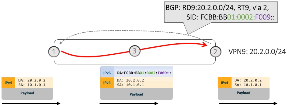
Network Slices with Flexible Algorithm
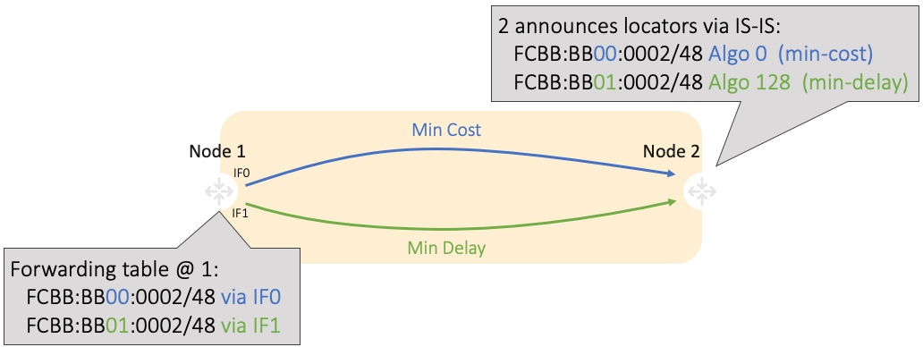
Consider an SR domain with two distinct network slices, each assigned a /32 uSID Locator Block:
In the example below, the SR domain has 2 network slices. Each slice is assigned a /32 uSID Locator Block.
A slice can be realized with a user-defined Flex-Algo instances (for example, Flex Algo 128 = min-delay)
-
Min-Cost Slice — FCBB:BB00/32
-
Min-Delay Slice — FCBB:BB01/32
SR node2 gets a Shortest-Path Endpoint uSID (uN) from each slice:
-
uN min-cost of Node2 — FCBB:BB00:0002/48
-
uN min-delay of Node2 — FCBB:BB01:0002/48
Node2 announces locators via IS-IS:
-
FCBB:BB00:0002/48 Algo 0 (min-cost)
-
FCBB:BB01:0002/48 Algo 128 (min-delay)

IS-IS in Node1 computes shortest paths for each locator and programs them in the FIB:
Node1 and Node2 are PEs of a common VPN. PEs advertise VPN routes via BGP with different transport SLAs. For example, traffic to a set of prefixes is to be delivered over the min-cost slice, while for another set of prefixes is to be delivered over the min-delay slice. To achieve this, the egress PE’s service route advertisement includes the locator of the intended transport SLA type.
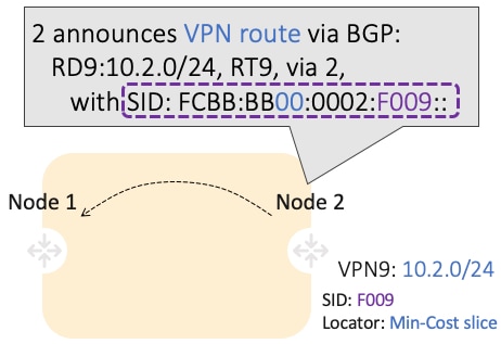
Use-case: VPN over Min-Cost Slice (Control Plane Behavior)
-
Intuitive uSID program for routes advertised by Node2:
-
Within the Min-Cost Slice (FCBB:BB00)
-
Follow the shortest-path to Node2 (0002)
-
Execute VPN9 decapsulation function at Node2 (F009)
-
-
Hardware Efficiency
-
Egress PE Node2 processes multiple uSIDs with a single /64 lookup
-
FCBB:BB00:0002:F009/64
-
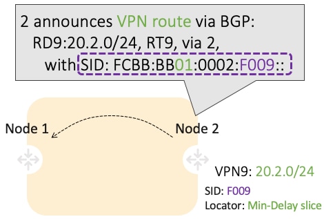
Use-case: VPN over Min-Delay Slice (Control Plane Behavior)
-
Intuitive uSID program for routes advertised by Node2:
-
Within the Min-Delay Slice (FCBB:BB01)
-
Follow the shortest-path to Node2 (0002)
-
Execute VPN9 decapsulation at Node2 (F009)
-
-
Hardware Efficiency
-
Egress PE 2 processes multiple uSIDs with a single /64 lookup
-
FCBB:BB01:0002:F009/64
-
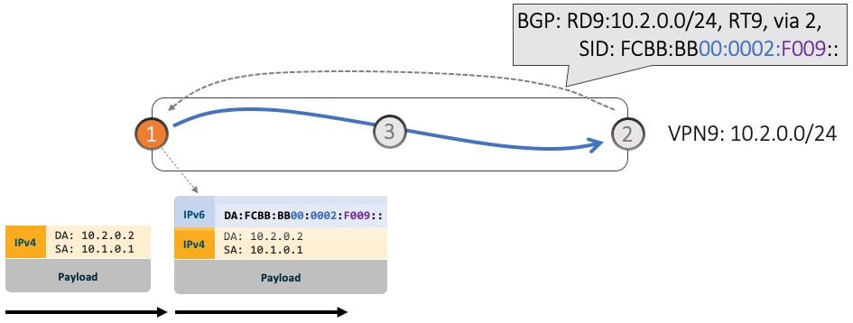
Use-case: VPN over Min-Cost Slice (Data Plane Behavior)
-
Ingress PE (Node 1) learns via BGP that prefix 10.2.0.0/24 in VPN9 is reachable via SID FCBB:BB00:0002:F009
-
Node 1 programs the prefix with “VPN Encaps” behavior
-
When receiving traffic with DA IP matching the prefix 10.2.0.0/24 FIB entry, Node 1 encapsulates the incoming packet into IPv6 with DA of FCBB:BB00:0002:F009
-
SRv6 allows for seamless deployment where any transit node (SRv6-capable or not) simply routes based on a /48 longest prefix match lookup.
For example, transit node (Node 3) forwards traffic along the Algo 0 (min-cost) shortest path for the remote prefix FCBB:BB00:0002::/48.

-
Egress PE (Node 2) matches local SID FCBB:BB00:0002:F009/64. Node 2 applies “VPN Decaps” behavior into VRF9 by removing the IPv6 encapsulation and looking up the payload’s DA on the corresponding VPN table.

Use-case: VPN over Min-Delay Slice (Data Plane Behavior)
-
Ingress PE (Node 1) learns via BGP that prefix 20.2.0.0/24 in VPN9 is reachable via SID FCBB:BB01:0002:F009
-
Node 1 programs the prefix with “VPN Encaps” behavior
-
When receiving traffic with DA IP matching the prefix 20.2.0.0/24 FIB entry, Node 1 encapsulates the incoming packet into IPv6 with DA of FCBB:BB01:0002:F009
-
Transit node (Node 3) forwards traffic along the Algo 128 (min-delay) shortest path for the remote prefix FCBB:BB01:0002::/48.
-
Egress PE (Node 2) matches local SID FCBB:BB01:0002:F009/64. Node 2 applies “VPN Decaps” behavior into VRF9 by removing the IPv6 encapsulation and looking up the payload’s DA on the corresponding VPN table.
SRv6 policy counters
Policy counters are metrics used in networking that
-
measure and report traffic statistics for specific policies,
-
enable network administrators to monitor and manage network performance, and
-
support capacity planning by providing detailed usage insights.
|
Feature Name |
Release Information |
Feature Description |
|---|---|---|
|
SRv6 policy counters (POL.CP.SL.INT.E) |
Release 25.3.1 |
Introduced in this release on: Fixed Systems (8200 [ASIC: Q200, P100], 8700 [ASIC: P100, K100], 8010 [ASIC: A100]); Centralized Systems (8600 [ASIC:Q200]); Modular Systems (8800 [LC ASIC: Q200, P100]) Network administrators can now monitor and manage network performance, capacity planning, and traffic engineering by reviewing the policy counters (POL.CP.SL.INT.E) in SRv6-TE. This feature is enabled by default. |
SRv6 policy traffic counters
POL.CP.SL.INT.E stands for Per-SR-policy, per Candidate-Path, per-Segment-List, per-interface, egress traffic counter. This counter in SRv6 is used to measure and report traffic statistics for specific paths and interfaces within a network policy. It provides granular insights into the traffic flow through different segments and interfaces of a network policy, enabling effective network management and optimization.
To optimize hardware resources, you can use the hw-module profile cef te-tunnel highscale-no-ldp-over-te command to enable high-scale MPLS-TE tunnel support in CEF while disabling LDP-over-TE. For more information, see MPLS Configuration Guide for Cisco 8000 Series Routers.
Benefits of SRv6 policy counters POL.CP.SL.INT.E
The benefits of SRv6 policy counters POL.CP.SL.INT.E are:
-
Network optimization: By analyzing the detailed traffic data, network operators can make informed decisions to optimize the network, such as rerouting traffic to avoid congestion.
-
Troubleshooting: In case of network issues, these counters provide the necessary data to quickly identify and resolve problems.
-
Policy validation: Ensuring that the implemented SRv6 policies are functioning as intended and making adjustments as needed based on the counter data.
Verify SRv6 policy counters
The purpose of this task is to retrieve SRv6 policy counter information.
Procedure
|
Run the following show commands to view the policy counter details. Example: |
 Feedback