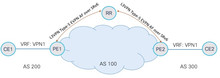
IPv4 L3VPN active-standby redundancy using port-active mode
An IPv4 L3VPN active-standby redundancy using port-active mode is a Segment Routing IPv6 (SRv6) service that
-
provides all-active per-port load balancing for multihoming
-
determines traffic forwarding based on specific interfaces rather than per-flow across multiple Provider Edge (PE) routers, and
-
enables faster convergence by using designated forwarder (DF) election through modulo calculation, where byte 10 of the Ethernet Segment Identifier (ESI) is used to detect the active PE router and bring down the standby PE router’s interface
Enhanced multihoming efficiency with active-standby redundancy using port-active mode
|
Feature Name |
Release Information |
Feature Description |
|---|---|---|
|
IPv4 L3VPN active-standby redundancy using port-active mode |
Release 25.4.1 |
Introduced in this release on: Fixed Systems (8700 [ASIC: K100])(select variants only*) This feature enables active-standby redundancy using port-active mode for IPv4 L3VPN services over SRv6, providing high availability and efficient load balancing in multihomed networks. Traffic forwarding is based on specific interfaces, not per flow, across multiple Provider Edge (PE) routers. Rapid failover is achieved through designated forwarder (DF) election using modulo calculation on byte 10 of the Ethernet Segment Identifier (ESI). This enhances network resilience and operational efficiency by ensuring faster convergence and minimal service disruption. This feature is now supported on:
|
This feature ensures high availability and efficient traffic management in multihomed IPv4 L3VPN networks. By leveraging per-port active-standby redundancy, it provides robust load balancing and rapid failover, minimizing service disruption. The port-active mode simplifies traffic forwarding decisions based on specific interfaces and accelerates convergence using DF election, enhancing overall network resilience and operational efficiency.
Benefits of active-standby redundancy using port-active mode
-
Load balancing performed per interface (port), simplifying forwarding decisions.
-
DF election based on modulo calculation of the ESI to identify the active PE.
-
Standby PE interfaces disabled to avoid forwarding loops and conflicts.
-
Rapid failover and convergence by re-electing the DF upon link or port failure.
-
Enhanced network efficiency, reliability, and resilience in multihomed IPv4 L3VPN deployments.
Restrictions of active-standby redundancy using port-active mode
-
This feature can only be configured on bundle interfaces.
-
When an EVPN Ethernet segment is configured with port-active load-balancing mode, you must not configure ACs of that bundle on bridge domains that have an EVPN instance (EVI) configured.
-
EVPN Layer 2 bridging service is incompatible with port-active load-balancing mode and therefore cannot be used together.
How SRv6 services for L3VPN active-standby redundancy using port-active mode work
Summary
The SRv6 Services for L3VPN Active-Standby Redundancy using Port-Active Mode process ensures high availability and efficient traffic management. PE routers exchange EVPN ES routes via BGP, then individually determine an ordered list of PEs. A modulo calculation designates one PE as the active forwarder (DF), while others disable their bundles. In the event of a failure, the active DF withdraws its route, prompting a re-election and quick resumption of forwarding duties by a newly elected DF.
Workflow
These stages describe how SRv6 services for IPv4 L3VPN active-standby redundancy using port-active mode works:
- PE routers exchange EVPN ES routes. All PE routers connected to the multihomed ES exchange EVPN ES routes across BGP.
-
Each PE router creates an ordered list and assigns an ordinal.
- Each PE router creates an ordered list of all PE IP addresses connected to the ES.
- Each PE router assigns itself an ordinal based on its position in this list.
-
A modulo calculation determines the Designated Forwarder (DF).
- Using the ordinals, a modulo calculation determines which PE becomes the Designated Forwarder (DF) for the ES.
- For the modulo calculation, byte 10 of the Ethernet Segment Identifier (ESI) is used.
-
The elected DF forwards traffic and non-DF PEs disable bundles.
- The PE elected as DF actively forwards traffic for the ES.
- All other PEs (non-DF) disable their respective bundles for that ES.
- The active DF PE withdraws its ES route upon failure. Upon a link or port failure, the active DF PE withdraws its ES route.
-
A new DF election is triggered, and a new PE resumes forwarding.
- This withdrawal triggers a new DF election among all PEs servicing the ES.
- A new PE is elected as DF and resumes forwarding duties.
Configure SRv6 services L3VPN active-standby redundancy using port-active mode
Configure SRv6 services to provide L3VPN active-standby redundancy using port-active mode under an Ethernet Segment (ES).
Procedure
|
Step 1 |
Example: |
|
Step 2 |
Configure the physical interface to join the bundle. Example: |
|
Step 3 |
Configure the BGP address family session for EVPN. Example: |
|
Step 4 |
Running configuration active-standby redundancy using port-active mode. Example: |
|
Step 5 |
Verify the SRv6 services L3VPN active-standby redundancy using port-active mode configuration. |

 Feedback