BGP Routing Optimisation and Convergence Techniques

Border Gateway Protocol (BGP) is essential for inter-domain routing, but often presents challenges in scalability, path optimization, and convergence. This chapter introduces advanced BGP techniques designed to overcome these issues. We explore methods for enhancing route reflection, accelerating fault recovery, enabling intelligent path selection, and streamlining route management.

BGP route reflectors

A BGP route reflector is a type of internal BGP (iBGP) router that

  • allows iBGP routers to share routes without needing every router to peer with every other router

  • designates specific iBGP peers as clients to simplify network topology, and

  • uses a cluster ID to coordinate with other route reflectors for redundancy and to prevent routing loops.

A route reflector client is an iBGP peer that receives routes from the route reflector and advertises its own learned routes back.

A cluster is a group consisting of a route reflector and its clients, and is identified by a unique cluster ID.

Route reflector mechanism:

In traditional iBGP networks, every iBGP router must peer with all other iBGP routers, which increases complexity as the network grows. BGP route reflectors address this scalability challenge by allowing designated routers (the route reflectors) to handle route sharing and peering. Only route reflectors maintain full iBGP sessions with each other, while other routers (clients) peer only with their assigned route reflector.

Redundancy with multiple route reflectors:

To increase redundancy and avoid a single point of failure, you can configure multiple route reflectors within the same cluster. Each reflector in the cluster uses the same 4-byte cluster ID. This ensures correct route learning and prevents routing loops.

Support for duplicate cluster IDs:

Special configuration options, such as the cluster-id allow-equal command, enables a router to accept routes with duplicate cluster IDs, but this option should be used carefully.

Configure a route reflector for BGP

Configure a router to function as a BGP route reflector and designate BGP neighbors as route-reflector clients within a specified cluster.

Before you begin

  • Know the autonomous system (AS) number and desired cluster ID.

  • Determine which BGP neighbors should be route-reflector clients.

Procedure


Configure a router as a BGP route reflector and configure the neighbor as its client.

Example:

Router(config)# router bgp 120
Router(config-bgp)# bgp cluster-id 192.168.0.1
Router(config-bgp)# neighbor 172.16.0.2
Router(config-bgp-nbr)# remote-as 65501
Router(config-bgp-nbr)# address-family ipv4 unicast
Router(config-bgp-nbr-af)# route-reflector-client

BGP multiple cluster IDs

A BGP multiple cluster ID is a route reflection feature that

  • allows a route reflector to have both a global cluster ID and additional cluster IDs assigned to individual clients (neighbors)

  • automatically adjusts the loop prevention mechanism based on CLUSTER_LIST to support multiple cluster IDs, and

  • enables a network administrator to disable client-to-client route reflection based on cluster ID.

Before the introduction of multiple cluster IDs, a device could have only a single, global cluster ID. With this feature, configuring per-neighbor cluster IDs allows greater flexibility and control in BGP route reflection.


Remember


The BGP multiple cluster IDs feature only works in the default VRF.


BGP optimal route reflectors

A BGP optimal route reflector (ORR) is a virtual route reflector function that

  • calculates the best BGP path from the perspective of each route reflector (RR) client

  • runs multiple shortest path first (SPF) calculations per RR client or cluster to ensure path optimality, and

  • enables flexible placement of virtual route reflectors (vRR) in service provider networks without compromising path selection accuracy.

Traditional BGP route reflector limitations

In traditional BGP deployments, a route reflector acts as a focal point within an autonomous system and advertises routes to RR clients based on the RR’s own path selection. When the RR is not optimally placed in the network topology, it can result in suboptimal routing decisions for RR clients, causing inefficient traffic flows.

Optimised client-specific routing with BGP ORR

BGP ORR addresses these limitations by running multiple SPF calculations from the perspective of each RR client or RR cluster. The system stores each client’s SPF results in a dedicated database, using these results to influence BGP best path selection. This process ensures every advertised route is optimal for the client’s specific network position, regardless of the vRR's location.

Benefits of BGP ORR

  • Calculates and advertises the best BGP path for each RR client’s viewpoint.

  • Enables vRR placement anywhere in the service provider network without sacrificing routing efficiency.

  • Allows network operators to scale RR memory and CPU resources according to operational requirements.

A service provider using network function virtualization (NFV) can deploy Cisco IOS XRv 9000 as a virtual route reflector in a central data center. BGP ORR optimizes routing for distributed RR clients, ensuring each receives the best available path despite the vRR’s remote placement.

Effect of BGP ORR on route reflector client path selection

The path a route reflector client selects in a BGP topology depends on whether BGP ORR is configured.

Example: BGP ORR topology

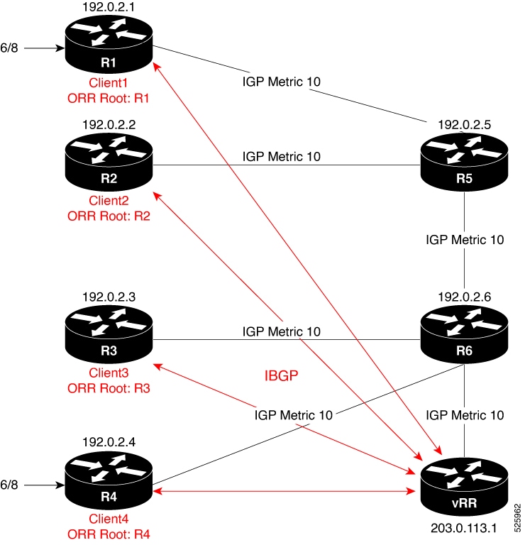
To illustrate the impact of BGP ORR on client path selection, consider the topology shown in Figure 1.

In this sample BGP topology, routers R1, R2, R3, R4, R5, and R6 are route reflector clients connected to a virtual route reflector (vRR). R1 and R4 advertise the prefix 6/8 to the vRR. Without BGP ORR, the vRR reflects the prefix based on its own path selection, which may not be optimal for all clients. With BGP ORR enabled, the vRR selects the best exit for each client based on the client’s location in the topology.

This table compares client path selection with and without BGP ORR:

Scenario Client (Example: R2) Exit point selected Selection basis
Without BGP ORR R2 R4 vRR selects best path from its own perspective
With BGP ORR configured R2 R1 vRR calculates best exit from the client's perspective (ORR Root: R2)

Key facts

  • Without BGP ORR:

    Route reflection uses the virtual route reflector’s (vRR) view of the network topology, which may not yield the optimal exit point for every client. In this case, the vRR considers R4 as the best path for all clients, including R2, even if R2 is topologically closer to R1.

  • With BGP ORR:

    The vRR evaluates topological distance from each client’s perspective (the ORR root), ensuring each client receives the route that represents its optimal exit point. For example, R2 receives the route from R1 if it is the closest.

Configure BGP ORR for a route reflector client

Enable optimal route reflection (ORR) on a virtual route reflector (vRR) for a specific client, apply the correct policies, ensure underlying MPLS TE support, and verify correct function.

Before you begin

  • Ensure you have administrative access to the vRR and root router.

  • Confirm that BGP and MPLS Traffic Engineering features are enabled and licensed on all relevant devices.

  • Gather these details:

    • BGP AS number

    • Client IP address

    • ORR root policy name

    • Required interface/loopback details

Procedure


Step 1

Enter BGP configuration mode and define the ORR statement using the client’s IP address and the appropriate ORR policy.

Example:

Router# configure
Router(config)# router bgp 6500
Router(config-bgp)# address-family ipv4 unicast
Router(config-bgp-af)# optimal-route-reflection g1 192.0.2.2
Router(config-bgp-af)# commit

Step 2

In BGP configuration mode, assign the ORR policy to the target neighbor (the RR client) for the relevant address family.

Example:

Router# configure
Router(config)# router bgp 6500
Router(config-bgp)# neighbor 10.0.0.1
Router(config-bgp-nbr)# address-family ipv4 unicast
Router(config-bgp-nbr-af)# optimal-route-reflection g1
Router(config-bgp-nbr-af)# commit

Step 3

On the root router, configure a minimal MPLS TE setup to advertise the router-ID that matches the configured root address on the vRR.

Example:

Router(config)# router isis 1
Router(config-isis)# is-type level-2-only 
Router(config-isis)# net 47.0000.0000.0005.00
Router(config-isis)# distribute link-state
Router(config-isis-af)# metric-style wide
Router(config-isis-af)# mpls traffic-eng level-2-only
Router(config-isis-af)# mpls traffic-eng router-id Loopback0

Step 4

Execute the show bgp command on the client (for example, R2) to verify whether the client received the best path.

Example:

R2# show bgp 10.0.0.0/8
Tue Apr  5 20:21:58.509 UTC
BGP routing table entry for 10.0.0.0/8
Versions:
  Process           bRIB/RIB  SendTblVer
  Speaker                  8           8
Last Modified: Apr  5 20:00:44.022 for 00:21:14
Paths: (1 available, best #1)
  Not advertised to any peer
  Path #1: Received by speaker 0
  Not advertised to any peer
  Local
    192.0.2.1 (metric 20) from 209.165.113.1 (192.0.2.1)
      Origin incomplete, metric 0, localpref 100, valid, internal, best, group-best
      Received Path ID 0, Local Path ID 1, version 8
      Originator: 192.0.2.1, Cluster list: 203.0.113.1

Step 5

Execute the show bgp command on the vRR to verify that the client is in the correct update-group and that the best path is reflected as intended.

Example:

VRR# show bgp 10.0.0.0/8
Thu Apr 28 13:36:42.744 UTC
BGP routing table entry for 10.0.0.0/8
Versions:
Process bRIB/RIB SendTblVer
Speaker 13 13
Last Modified: Apr 28 13:36:26.909 for 00:00:15
Paths: (2 available, best #2)
Advertised to update-groups (with more than one peer):
0.2
Path #1: Received by speaker 0
ORR bestpath for update-groups (with more than one peer):
0.1
Local, (Received from a RR-client)
192.0.2.1 (metric 30) from 192.0.2.1 (192.0.2.1)
Origin incomplete, metric 0, localpref 100, valid, internal, add-path
Received Path ID 0, Local Path ID 2, version 13
Path #2: Received by speaker 0
Advertised to update-groups (with more than one peer):
0.2
ORR addpath for update-groups (with more than one peer):
0.1
Local, (Received from a RR-client)
192.0.2.4 (metric 20) from 192.0.2.4 (192.0.2.4)
Origin incomplete, metric 0, localpref 100, valid, internal, best, group-best
Received Path ID 0, Local Path ID 1, version 13

Step 6

Execute the show bgp update-group 0.1 command, and verify whether the client (R2) is in update-group 0.1.

Example:

VRR# show bgp update-group 0.1 
Thu Apr 28 13:38:18.517 UTC

Update group for IPv4 Unicast, index 0.1:
Attributes:
Neighbor sessions are IPv4
Internal
Common admin
First neighbor AS: 65000
Send communities
Send GSHUT community if originated
Send extended communities
Route Reflector Client
ORR root (configured): g1; Index: 0
4-byte AS capable
Non-labeled address-family capable
Send AIGP
Send multicast attributes
Minimum advertisement interval: 0 secs
Update group desynchronized: 0
Sub-groups merged: 0
Number of refresh subgroups: 0
Messages formatted: 5, replicated: 5
All neighbors are assigned to sub-group(s)
Neighbors in sub-group: 0.2, Filter-Groups num:1
Neighbors in filter-group: 0.2(RT num: 0)
192.0.2.2

Step 7

Run the show orrspf database command to validate cost and root selection.

Example:

VRR# show orrspf database g1 
Thu Apr 28 13:39:20.333 UTC

ORR policy: g1, IPv4, RIB tableid: 0xe0000011
Configured root: primary: 192.0.2.2, secondary: NULL, tertiary: NULL
Actual Root: 192.0.2.2, Root node: 2000.0100.1002.0000

Prefix Cost
203.0.113.1 30
192.0.2.1 20
192.0.2.2 0
192.0.2.3 30
192.0.2.4 30
192.0.2.5 10
192.0.2.6 20

Number of mapping entries: 8


BGP Accept Own

A BGP Accept Own mechanism is a BGP routing feature that

  • allows a BGP speaker to accept VPN routes that it originally advertised but receives back from a route-reflector

  • uses the special ACCEPT_OWN community attribute to bypass standard self-origination filters such as ORIGINATOR_ID and NEXTHOP checks, and

  • enables centralized control of route imports across VRFs in MPLS VPN environments without requiring configuration changes on provider edge routers.

Default BGP route rejection behavior:

By default, according to BGP protocol (RFC 4271), a BGP speaker rejects routes it originated if they are returned by a route-reflector.

BGP Accept Own feature:

The BGP Accept Own feature changes this behavior: when the ACCEPT_OWN community is attached to a prefix (by a route-reflector via an outbound route-policy), it signals the receiving router to accept the reflected route even if it originally advertised that prefix. This is especially valuable in MPLS VPN extranets, where route import/export must be managed centrally.

Use case: Extranet auto-configuration in MPLS VPNs:

One primary use case is auto-configuration of extranets within MPLS VPNs. Conventionally, controlling route imports between VRFs for extranets requires updating import route-targets or policies on each PE router. With BGP Accept Own, route-reflectors can manage which prefixes are imported between VRFs without additional PE configuration. This approach makes operations more scalable and flexible.

Route-reflector handling and community propagation

Route-reflectors attach the ACCEPT_OWN community when advertising selected prefixes to the originating PE. The addition of this community should be limited to outbound policies targeting only the originator, to avoid unnecessary propagation. The InterAS route-reflector may also adjust the set of route targets (RTs) when sending routes with the ACCEPT_OWN community. This enables precise control over which VRFs receive the reflected routes.

Preference for Accept Own community in best path selection

Once the Accept Own community is attached to a route and propagated by a route reflector, remote PE routers apply these best path selection rules.

  • The best path algorithm prefers a route that contains the Accept Own community over one that does not.

  • This preference is evaluated immediately before the IGP metric comparison step in the best path selection process.

  • If a remote PE receives an Accept Own path from one route reflector and a non-Accept Own path from another, and both paths are otherwise identical, it selects the Accept Own path.

  • After a path is selected, the import process operates on the Accept Own path.

This behavior ensures that when multiple otherwise identical routes exist, routes with the Accept Own community are consistently preferred during best path selection on remote PEs.

How Accept Own routes are processed in BGP VPN configurations

Summary

The key components involved in the process are:

  • Customer edge (CE) router: A router that originates the desired prefix to the provider network.

  • Provider edge (PE) router: A router that owns both the customer VRF and service VRF, participates in BGP VPN address families, and communicates with route reflectors.

  • Intra-AS route reflector (IntraAS-RR): A route reflector (RR) that reflects routes within the same autonomous system.

  • Inter-AS route reflector (InterAS-RR): An RR that adds the ACCEPT_OWN community and updates route targets before reflecting the route further.

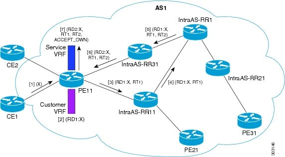
A customer prefix is advertised from the CE to the PE, then reflected through multiple route reflectors. During this process, route targets and the ACCEPT_OWN community are added. The PE ultimately installs the prefix in the service VRF with updated attributes, enabling precise control over route import between VRFs.

Workflow

Figure 1. BGP Accept Own configuration example

These stages describe how Accept Own routes are processed in BGP VPN configurations:

  1. Prefix origination: The CE router advertises prefix X to the PE.
  2. Customer VRF installation: The PE installs prefix X in the Customer VRF as (RD1:X).
  3. Initial advertisement to route reflector: The PE advertises prefix X to the IntraAS-RR as (RD1:X, RT1).
  4. Inter-cluster reflection: The IntraAS-RR sends the route to the InterAS-RR as (RD1:X, RT1).
  5. Community and route target update: The InterAS-RR attaches RT2 to prefix X on inbound and adds the ACCEPT_OWN community on outbound, then advertises the route to another IntraAS-RR.
  6. Reflection back to PE: The second IntraAS-RR advertises the updated prefix to the PE.
  7. Service VRF installation: The PE installs prefix X in the Service VRF with new route targets and the ACCEPT_OWN community (RD2:X, RT1, RT2, ACCEPT_OWN).

Result

The Accept Own process allows the same PE to import its own originated VPN prefixes into a different VRF. This supports extranet configurations with policy-driven control managed by the route reflector, without requiring modification of import policies or route targets on the PE.

Configure BGP Accept Own

Enable the BGP Accept Own feature so that the router accepts self-originated VPN routes containing the Accept_Own community attribute.

Before you begin

  • Collect the required neighbor IP address, remote autonomous system number, and determine which address-family (VPNv4 or VPNv6) requires Accept Own.

Procedure


Step 1

Enter BGP configuration mode, specify the BGP neighbor, and enable Accept Own for the neighbor.

Example:

Router# configure
Router(config)# router bgp 100
Router(config-bgp)# neighbor 192.0.2.3
Router(config-bgp-nbr)# remote-as 100
Router(config-bgp-nbr)# update-source Loopback0
Router(config-bgp-nbr)# address-family vpnv6 unicast
Router(config-bgp-nbr-af)# accept-own

Step 2

(Optional) Use the inheritance-disable keyword to prevent inheritance of Accept Own from parent configuration.

Example:


Router(config-bgp-nbr-af)# accept-own inheritance-disable

This example shows how to configure BGP Accept Own on a PE router.

router bgp 100
neighbor 10.1.1.1
remote-as 100
update-source Loopback0 address-family vpnv4 unicast
route-policy pass-all in accept-own
route-policy drop_111.x.x.x out
!
address-family vpnv6 unicast route-policy pass-all in accept-own
route-policy drop_111.x.x.x out
!
!

This example shows an InterAS-RR configuration for BGP Accept Own.

router bgp 100
neighbor 192.0.2.45
remote-as 100
update-source Loopback0 address-family vpnv4 unicast
route-policy rt_stitch1 in route-reflector-client route-policy add_bgp_ao out
!
address-family vpnv6 unicast route-policy rt_stitch1 in route-reflector-client route-policy add_bgp_ao out
!
!
extcommunity-set rt cs_100:1 100:1
end-set
!
extcommunity-set rt cs_1001:1 1001:1
end-set
!
route-policy rt_stitch1
if extcommunity rt matches-any cs_100:1 then set extcommunity rt cs_1000:1 additive
endif
end-policy
!
route-policy add_bgp_ao
set community (accept-own) additive end-policy
!

Best-external paths

A best-external path is a BGP route selection mechanism that

  • identifies the most optimal external path for a prefix when the current best path is internal (iBGP)

  • enables advertisement of both the best and a backup path to peers to improve redundancy, and

  • ensures internal routers are prepared with an external alternative if the primary iBGP path fails.

Selection procedure:

  1. Determine the best path from all available paths for the prefix.

  2. Remove the current best path.

  3. Remove all remaining internal paths.

  4. From the remaining paths, remove those with the same next hop as the current best path.

  5. Use the BGP best path selection algorithm on the remaining paths to identify the best-external path.

Enhancing failover with the BGP best-external path feature

When a router’s optimal path to a prefix comes from an iBGP peer, the router activates the best-external path feature to select and advertise the next best eBGP route to its internal peers. This function allows internal routers to promptly switch to a valid external route if the iBGP path becomes unavailable. As a result, the network avoids delays due to full path recalculation.

Configure best-external path advertisement

Enable the router to advertise the best-external BGP paths for a specific address family.

Before you begin

  • Know your BGP autonomous system (AS) number.

Follow this step to configure best-external path advertisement:

Procedure


Enter global configuration mode, and enable best-external path advertisement.

Example:

Router(config)# router bgp 100
Router(config-bgp)# address-family l2vpn vpls-vpws
Router(config-bgp-af)# advertise best-external

BGP Prefix Independent Convergence

A BGP Prefix Independent Convergence (PIC) feature is a network routing enhancement that

  • pre-computes and stores both primary and backup (best external) paths for each destination prefix in the Routing Information Base (RIB) and Forwarding Information Base (FIB)

  • enables instantaneous switch to a backup path in the event of a primary path failure, minimizing convergence time and network downtime, and

  • is especially beneficial for large-scale BGP deployments and networks with route reflectors.

Standard BGP convergence: prefix-dependent process

Standard BGP convergence is "prefix-dependent": each BGP router advertises only its current best path for a destination prefix. When the best path fails, routers send withdrawal messages, recalculate new best paths, and re-advertise to neighbors until all routers converge on a new path. This iterative process is slow, especially in networks with route reflectors.

Accelerated failover with Prefix Independent Convergence (PIC)

With PIC, BGP routers advertise their best external paths and pre-install backup paths in the FIB. When a failure occurs, the router can immediately switch to the backup path with a single operation, greatly accelerating convergence and reducing packet loss.

Attribute Prefix-Dependent Convergence Prefix Independent Convergence (PIC)
Awareness of backup paths No Yes
Convergence time Slow, iterative Fast, single-operation
FIB programming Only best path Best and backup paths
Scalability Limited in large networks Optimized for large deployments

Benefits of Prefix Independent Convergence

  • Rapid recovery from link or node failures with minimal traffic disruption.

  • Consistent failover times even as network scale grows.

  • Improved reliability and service continuity for business-critical applications.

Selecting backup paths

Selecting backup paths ensures network resilience by identifying and programming an optimal alternative route in case the primary path fails.

Summary

The key components involved in the process are:

  • Routing Information Base (RIB): A database that maintains all available routing information, including both primary and backup paths.

  • Forwarding Information Base (FIB): A table that programs the selected backup path to forward data packets efficiently when needed.

  • Best path algorithm: An algorithm that determines the best available path and the most suitable backup path from multiple candidates for each prefix.

The router uses the best path algorithm to select a primary path for a prefix. Next, the router removes the primary path and any paths that share its next hop. The algorithm runs again on the remaining paths to find the optimal backup path. The optimal backup is pre-programmed into the RIB and FIB for rapid failover if the primary path fails.

Workflow

These stages describe the process of selecting backup paths:

  1. The router applies the best path algorithm to the available set of paths for a prefix to identify the primary (best) path.
  2. The router excludes the best path from the set of available paths.
  3. The router removes any paths that have the same next hop as the best path.
  4. The router runs the best path algorithm again on the reduced set to select the optimal backup path.
  5. The router programs the selected backup path into the RIB and FIB to ensure it is ready to take over if needed.

How prefix-independent convergence with route reflectors works

Prefix-independent convergence (PIC) with route reflectors optimizes BGP network failover by rapidly switching traffic to pre-programmed backup paths, minimizing convergence delays when a primary path fails.


Note


To use the BGP PIC feature with route reflectors, each provider edge (PE) router must be configured with a unique route distinguisher (RD) within the same VRF. Without unique RDs, routes from different PEs appear to belong to the same network, preventing the route reflector from correctly identifying and calculating the best backup path.

Summary

The key components involved in the process are:

  • Primary provider edge (PE) router: A PE router that advertises the primary route for traffic destined to remote PEs.

  • Backup provider edge (PE) router: A PE router that maintains and advertises the backup (best external) path.

  • Remote provider edge (PE) router: A PE router that selects between primary and backup paths based on announcements from core PEs.

  • Route reflector: A router that distributes iBGP route information and requires unique route distinguishers (RDs) for proper path selection.

  • Forwarding information base (FIB) or Routing information base (RIB): Stores and switches between primary and backup forwarding entries.

The process ensures fast BGP convergence by pre-installing both primary and backup paths in router forwarding tables (RIB and FIB). During normal operation, the primary path is used, while the backup path remains ready. If the primary path fails, the router instantly switches to the pre-programmed backup, enabling immediate traffic redirection with minimal delay and packet loss.

Workflow

These stages describe the process:

  1. Pre-programming of paths: Both primary and backup (best external) routes for each prefix are programmed into the RIB and FIB of relevant routers.
  2. Initial operation:
    • The primary PE advertises the local-pref attribute to designate itself as the preferred route; the backup PE advertises the backup path.
    • The remote PE receives both primary and backup paths but prefers the primary.
    • The route reflector uses unique route distinguishers to differentiate routes from different PEs within the VRF.
  3. Primary path failure: In the event of primary path failure, primary PE signals the core to withdraw its route. The backup PE immediately advertises the backup path as the new best route.
  4. Network convergence: The remote PE quickly recalculates and updates its primary path, switching from primary to backup. The FIB instantly reassigns traffic to the backup path using the pre-installed forwarding entry for that prefix.
  5. Traffic resumption: Network traffic resumes with minimal delay, as the backup route is already available in the FIB.

Configure BGP PIC in provider edge networks

Enable Prefix Independent Convergence (BGP PIC) to improve network resiliency by ensuring rapid failover between primary and backup paths in provider edge networks.

Consider this sample topology.

Figure 2. Prefix Independent Convergence in provider edge networks

For traffic traveling from the customer edge (CE) router to the provider edge (PE3) router, the BGP local preference (local-pref) attribute is used to determine the preferred path. The path CE → PE1 → PE3 is selected as the primary route, while CE → PE2 → PE3 is set as the backup route. Within the provider's core network, the path PE1 → P → PE2 is chosen as the best internal route between provider edge routers.

Before you begin

  • Confirm all loopback and network interfaces are configured according to your topology.

  • Ensure VRFs for the provider core network are set up.

Follow these steps to configure BGP PIC in provider edge networks.

Procedure


Step 1

On router PE1, configure BGP to install additional paths and set the label retention period.

Example:

Router(config)# router bgp 10
Router(config-bgp)# vrf foo
Router(config-bgp-vrf)# address-family ipv4 unicast
Router(config-bgp-vrf-af)# additional-path install
Router(config-bgp-vrf-af)# label-retention 10

Step 2

On router PE2, configure BGP to advertise the best external path, allocate labels, and enable additional path installation.

Example:

Router(config)# router bgp 10
Router(config-bgp)# vrf foo
Router(config-bgp-vrf)# address-family ipv4 unicast
Router(config-bgp-vrf-af)# advertise-best-external label-alloc-mode
Router(config-bgp-vrf-af)# additional-path install

Step 3

On router PE3, configure BGP to install additional backup paths.

Example:

Router(config)# router bgp 10
Router(config-bgp)# vrf foo
Router(config-bgp-vrf)# address-family ipv4 unicast
Router(config-bgp-vrf-af)# additional-path install

Step 4

On router PE3, verify that BGP PIC is operational. Verify the presence of backup paths in the Forwarding Information Base (FIB).

Example:

Router# show cef 10.1.1.1/32 detail
Fri Oct 10 10:24:33.079 UTC
10.1.1.1/32, version 1, internal 0x40000001 (0xa94c0574) [1], 0x0 (0x0), 0x0
(0x0)
Updated Oct 9 16:49:06.795
Prefix Len 32, traffic index 0, precedence routine (0)
gateway array (0xa8d9b130) reference count 4, flags 0x80200, source rib
(3),
[1 type 3 flags 0x901101 (0xa8ec6b90) ext 0x0 (0x0)]
LW-LDI[type=0, refc=0, ptr=0x0, sh-ldi=0x0]
Level 1 - Load distribution: 0
[0] via 10.24.0.1, recursive
via 10.24.0.1, 3 dependencies, recursive
next hop 10.24.0.1 via 10.24.0.1/32
via 10.24.0.2, 3 dependencies, recursive, backup
next hop 10.24.0.2 via 10.24.0.2/32
Load distribution: 0 (refcount 1)
Hash OK Interface Address
0 Y MgmtEth0/RP0/CPU0/0 10.24.0.1

Configure BGP PIC Option B between autonomous systems

Configure BGP PIC for inter-AS Option B scenarios to ensure fast convergence and backup path installation between autonomous systems.

Consider this sample topology:

Figure 3. Prefix-Independent Convergence between autonomous systems

For traffic going from router PE1 to router PE2, ASBR1 acts as the primary router and ASBR2 as the backup router. The primary eBGP path is ASBR1 → ASBR3, while the backup path is ASBR2 → ASBR4.

For traffic traveling in the opposite direction, from router PE2 to router PE1, ASBR3 serves as the primary router and ASBR4 as the backup router. In this case, the primary eBGP path is ASBR3 → ASBR1, and the backup path is ASBR4 → ASBR2.

Before you begin

  • Ensure that you have configured the loopback and network interfaces as per the illustrated topology.

Follow these steps to configure BGP PIC Option B between autonomous systems.

Procedure


Step 1

On router ASBR1, configure BGP additional-path and label retention.

Example:

Router(config)# router bgp 10
Router(config-bgp)# address-family vpnv4 unicast
Router(config-bgp-af)# additional-path install
Router(config-bgp-af)# label-retention 10

Step 2

On router ASBR2, configure advertisement and installation of backup paths.

Example:

Router(config)# router bgp 10
Router(config-bgp)# address-family vpnv4 unicast
Router(config-bgp-af)# advertise-best-external label-alloc-mode
Router(config-bgp-af)# additional-path install

Step 3

Similarly, repeat the above configuration steps on router ASBR3 for traffic from PE2 to PE1, and on Router ASBR4 to advertise and install backup paths for that traffic direction.

Step 4

Use the show cef command on router PE2 (for traffic from PE1 to PE2) or on router PE1 (for traffic from PE2 to PE1) to verify BGP PIC operation.

Example:

Router# show cef 10.1.1.1/32 detail

Fri Oct 10 10:24:33.079 UTC
10.1.1.1/32, version 1, internal 0x40000001 (0xa94c0574) [1], 0x0 (0x0), 0x0
(0x0)
Updated Oct 9 16:49:06.795
Prefix Len 32, traffic index 0, precedence routine (0)
gateway array (0xa8d9b130) reference count 4, flags 0x80200, source rib
(3),
[1 type 3 flags 0x901101 (0xa8ec6b90) ext 0x0 (0x0)]
LW-LDI[type=0, refc=0, ptr=0x0, sh-ldi=0x0]
Level 1 - Load distribution: 0
[0] via 10.24.0.1, recursive
via 10.24.0.1, 3 dependencies, recursive
next hop 10.24.0.1 via 10.24.0.1/32
via 10.24.0.2, 3 dependencies, recursive, backup
next hop 10.24.0.2 via 10.24.0.2/32
Load distribution: 0 (refcount 1)
Hash OK Interface Address
0 Y MgmtEth0/RP0/CPU0/0 10.24.0.1

Step 5

Use the show bgp vrf foo command to verify the presence of the backup (best external) path for BGP.

Example:

Router# show bgp vrf foo 10.1.1.1/32

BGP routing table entry for 10.1.1.1/32
Versions:
Process bRIB/RIB SendTblVer
Speaker 6 6
Local Label: 3
Paths: (1 available, best #1)
Advertised to peers (in unique update groups):
10.10.10.1
Path #1: Received by speaker 0
10.1.1.1 from 10.1.1.1 (10.2.2.1)
Origin incomplete, metric 0, localpref 100, weight 32768, valid,
internal, best
10.2.2.2 from 10.2.2.2 (10.10.10.1)
Origin incomplete, metric 0, localpref 100, weight 32768, valid,
external, backup, best-external

Selective FIB download

A selective FIB download is a routing optimization feature that

  • selectively installs specific destination routes in the Forwarding Information Base (FIB) rather than all available routes

  • prevents traffic drops and black holes by ensuring traffic follows default routes when specific destination routes are unavailable, and

  • improves network reliability in multi-data center environments by adapting installed routes to current topology and failures.

Table 1. Feature History Table

Feature Name

Release Information

Feature Description

Selective FIB Download

Release 24.4.1

Introduced in this release on: Fixed Systems (8200, 8700); Centralized Systems (8600); Modular Systems (8800 [LC ASIC: Q200])

You can now selectively download BGP prefixes to the Routing Information Base (RIB) and Forwarding Information Base (FIB). This feature prevents traffic drops by ensuring that traffic follows default routes when specific destination routes are unavailable.

Network challenges in multi-data center environments

In multi-data center networks, links or connections between intermediate distribution facilities (IDFs) and their termination points may occasionally fail. When these connections are unavailable, affected IDFs lose precise routing paths to target destinations, complicating traffic management and potentially disrupting service delivery.

Importance of aggregate routes in traffic management

To manage traffic efficiently, a main routing node distributes it across available paths using aggregate routes. An aggregate route is an aggregated network prefix representing multiple destinations within a specific network layer. Intermediate nodes rely on these aggregate routes to forward traffic toward the appropriate IDFs, based on network availability and routing policies.

Risks of traditional routing with missing specific routes

When traffic arrives at an IDF that lacks specific destination routes, the presence of aggregate routes on that IDF can misdirect traffic to a null interface. This situation creates a “black hole,” where data packets are silently discarded, resulting in network connectivity problems and traffic loss.

Benefits of selective FIB download as a solution

Selective FIB download addresses these issues by preventing the installation of aggregate routes in the Routing Information Base (RIB) on local and connected intermediate nodes when direct routes to specific destinations are unavailable. Instead, the network relies on default routes to forward traffic toward alternative nodes that do possess the required specific routes. This approach ensures that traffic is intelligently rerouted through operational parts of the network, ultimately reaching its intended destination and avoiding black holes.

Address-family support

Selective FIB download supports IPv4 unicast and IPv6 unicast prefixes under the default VRF.

Configure selective FIB download

Configure selective FIB download to control which IP prefixes are installed or excluded from the router’s Forwarding Information Base (FIB) by policy.

Before you begin

  • Gather a list of IP prefixes that will be included in or excluded from the FIB.

  • Determine which community values to use, such as comm_1 for install and comm_2 for exclude.

Follow these steps to configure selective FIB download.

Procedure


Step 1

Configure a prefix set with IP prefixes.

Example:


Router(config)# prefix-set route_install
Router(config-pfx)# 10.1.11.1/8
Router(config-pfx)# 2001:DB8:01::/32,
Router(config-pfx)# 10.3.3.3/8
Router(config-pfx)# 2001:DB8:FF::/32
Router(config-pfx)# end-set
Router(config-pfx)# exit

Router(config)# prefix-set route_not_install
Router(config-pfx)# 192.168.0.1/16
Router(config-pfx)# 2001:DB8:88::/32
Router(config-pfx)# 192.168.20.11/16
Router(config-pfx)# 2001:DB8:99::/32
Router(config-pfx)# end-set
Router(config-pfx)# exit

Step 2

Define and attach the community to the prefix set.

Example:


Router(config)# route-policy prefix_set_rpl
Router(config-rpl)# if destination in route_install then
Router(config-rpl-if)# set community comm_1
Router(config-rpl-if)# elseif destination in route_not_install then
Router(config-rpl-if)# set community comm_2
Router(config-rpl-if)# endif
Router(config-rpl)# end-policy

Step 3

Configure the route policy to specify which routes to install in the RIB and which routes to exclude.

Example:

Router(config)# route-policy rib_install_tb_rpl
Router(config-rpl)# if community matches-any comm_1 then
Router(config-rpl-if)# pass
Router(config-rpl-if)# elseif community matches-any comm_2 then
Router(config-rpl-if)# drop
Router(config-rpl-if)# else
Router(config-rpl-else)# pass
Router(config-rpl-else)# endif
Router(config-rpl)# end-policy
Router(config)# router bgp 100
Router(config-bgp)# address-family ipv4 unicast
Router(config-bgp-af)# table-policy rib_install_tb_rpl
Router(config-bgp-af)# exit
Router(config-bgp)# address-family ipv6 unicast
Router(config-bgp-af)# table-policy rib_install_tb_rpl
Router(config-bgp-af)# exit

Step 4

Verify if the route is installed in RIB.

Example:

Router# show bgp ipv4 unicast 10.1.11.1/8
…
Paths: (1 available, no best path)
  Not advertised to any peer
  Path #1: Received by speaker 0
  Advertised IPv4 Unicast paths to peers (in unique update groups):
    10.2.2.2         10.1.2.3
  Local
    0.0.0.0 from 0.0.0.0 (10.1.1.1)
      Origin incomplete, metric 0, localpref 100, valid, local, permanent-path
      Received Path ID 0, Local Path ID 2, version 4
      Community: 11111:11111 22222:22222 33333:33333
      Origin-AS validity: not-found

Community: 11111:11111 22222:22222 33333:33333 in the sample output indicates the community comm_1.

Example:

Router# show route ipv4 10.1.11.1/8
Routing entry for 10.1.11.1/8
  Known via "bgp 65536", distance 200, metric 0, type locally generated
  Installed Jul 28 04:40:01.837 for 00:03:01
  Routing Descriptor Blocks
    directly connected, via Null0
      Route metric is 0
  No advertising protos.

Null0 in the sample output indicates that the route is installed in RIB.

These sample outputs illustrate scenarios where routes are not installed in the RIB.

Example:

Router# show bgp ipv4 unicast 192.168.0.1/16
Paths: (1 available, no best path)
  Not advertised to any peer
  Path #1: Received by speaker 0
  Advertised IPv4 Unicast paths to peers (in unique update groups):
    192.168.2.2         192.168.1.2.3
  Local
    0.0.0.0 from 0.0.0.0 (192.168.1.1)
      Origin incomplete, metric 0, localpref 100, valid, local, permanent-path
      Received Path ID 0, Local Path ID 2, version 14
      Community: 44444:44444
      Origin-AS validity: not-found

Community: 44444:44444 in the sample output indicates the community comm_2.

Example:

Router# show route ipv4 192.168.0.1/16

% Network not in table

% Network not in table indicates that this route is not installed in RIB.


BGP-RIB feedback mechanisms

A BGP-RIB feedback mechanism is a route advertisement control feature that

  • ensures that BGP announces routes to neighbors only after they are fully installed in the data plane

  • relies on coordination between the Routing Information Base (RIB) and the Forwarding Information Base (FIB) to track route installation status, and

  • prevents premature route advertisements that could otherwise cause packet loss during events such as router reloads or link failures.

Operation of the BGP-RIB feedback process

This mechanism works by having BGP wait for confirmation from the RIB that the installed routes are also present in the FIB. The RIB uses the BCDL feedback process to determine which versions of routes have been installed in the FIB and reports this information back to BGP.

Benefits of BGP-RIB feedback mechanisms

BGP only advertises routes that have been confirmed as fully installed, ensuring that network traffic is not directed to unprogrammed or unavailable paths. This enhances network reliability and prevents blackholing of traffic after topology changes.

Configure BGP to wait for feedback before sending updates

Ensure that BGP only advertises routes to neighbors after those routes are fully installed in the forwarding plane, preventing premature route announcements and possible packet loss.

Before you begin

  • Ensure that changes to route advertisement timing are acceptable for your network’s convergence policies.

Follow these steps to configure BGP to wait for feedback before sending updates to neighbors.

Procedure


Step 1

Use the update wait-install command to configure BGP to wait for RIB to confirm FIB installation before advertising routes.

Example:

Router# configure
Router(config)# router bgp 65500
Router(config-bgp)# address-family vpnv4 unicast
Router(config-bgp-af)# update wait-install

Step 2

Use the commands show bgp , show bgp neighbors , or show bgp process performance-statistics to verify and monitor the status.


BGP permanent networks

A BGP permanent network is a Border Gateway Protocol (BGP) feature that

  • enables the creation and advertisement of selected prefixes (IPv4 or IPv6) using route-policies

  • ensures these routes remain in the routing table until explicitly removed by an administrator, and

  • allows the configuration and selective advertising of permanent paths to designated BGP peers.

Permanent path behavior

For each designated prefix, BGP establishes a permanent path. The permanent path is considered less preferred than dynamic BGP paths learned from peers and is only downloaded into the Routing Information Base (RIB) if it is evaluated as the best path. Permanent paths are selectively advertised and persist independently of changing network conditions.

Restrictions on BGP permanent networks

Review these restrictions before you configure BGP permanent networks:

  • Use this feature only with IPv4 unicast and IPv6 unicast address families within the default Virtual Routing and Forwarding (VRF) context.

  • Ensure that permanent paths are selectively advertised and persist only as described. Permanent paths do not override dynamic BGP paths unless you select them as the best path.

Configure a BGP permanent network

Configure a BGP permanent network to ensure designated prefixes are always advertised.

Use this task when you need certain prefixes to remain permanently available in BGP advertisements, regardless of current route availability.

Before you begin

  • Ensure you have identified the IPv4 or IPv6 prefixes that should always be advertised.

Follow these steps to configure a BGP permanent network.

Procedure


Step 1

Define a prefix set for permanent network prefixes.

Example:


Router(config)# prefix-set PERMANENT-NETWORK-IPv4
Router(config-pfx)# 10.1.1.1/32,
Router(config-pfx)# 10.2.2.2/32,
Router(config-pfx)# 10.3.3.3/32
Router(config-pfx)# end-set

Step 2

Create a route policy to match the prefix set.

Example:


Router(config)# route-policy POLICY-PERMANENT-NETWORK-IPv4
Router(config-rpl)# if destination in PERMANENT-NETWORK-IPv4 then
Router(config-rpl)# pass
Router(config-rpl)# endif 

Step 3

Enter BGP configuration mode, and configure the permanent network using the route-policy you created.

Example:

Router(config)# router bgp 100
Router(config-bgp)# address-family ipv4 unicast
Router(config-bgp-af)# permanent-network route-policy POLICY-PERMANENT-NETWORK-IPv4

Step 4

Use the show bgp { ipv4 | ipv6 } unicast command to confirm that the specified prefixes are advertised as permanent networks.