
Table Of Contents
Configuring Client-Initiated Dial-In VPDN Tunneling
Prerequisites for Client-Initiated VPDN Tunneling
Restrictions for Client-Initiated VPDN Tunneling
Information About Client-Initiated VPDN Tunneling
Client-Initiated VPDN Tunneling
Client-Initiated VPDN Tunneling Using the L2TP or L2TPv3 Protocol
Client-Initiated VPDN Tunneling Using the PPTP Protocol
How to Configure Client-Initiated VPDN Tunneling
Configuring Client-Initiated Tunneling Using the L2TP or L2TPv3 Protocol
Configuring L2TP or L2TPv3 Client-Initiated VPDN Tunneling on the Local Peer
Configuring Client-Initiated Tunneling on the Tunnel Server for L2TP Tunnels
Configuring Client-Initiated Tunneling on the Tunnel Server for L2TPv3 Tunnels
Configuring L2TP Control Channel Parameters
Verifying an L2TP Control Channel
Configuring Client-Initiated VPDN Tunneling Using the PPTP Protocol
MPPE Encryption of PPTP Tunnels
Prerequisites for Configuring Client-Initiated VPDN Tunneling Using the PPTP Protocol
Restrictions for Configuring Client-Initiated VPDN Tunneling Using the PPTP Protocol
Configuring the Tunnel Server to Accept PPTP Tunnels
Configuring the Virtual Template on the Tunnel Server
Configuring MPPE on the ISA Card
Verifying a PPTP Client-Initiated VPDN Configuration
Configuration Examples for Client-Initiated VPDN Tunneling
Configuring L2TP Client-Initiated Tunneling: Example
Configuring L2TPv3 Client-Initiated Tunneling: Example
Verifying an L2TP Control Channel: Example
Configuring Client-Initiated VPDN Tunneling Using PPTP: Example
Feature Information for Client-Initiated VPDN Tunneling
Configuring Client-Initiated Dial-In VPDN Tunneling
Client-initiated dial-in virtual private dialup networking (VPDN) tunneling deployments allow remote users to access a private network over a shared infrastructure with end-to-end protection of private data. Client-initiated VPDN tunneling does not require additional security to protect data between the client and the Internet service provider (ISP) network access server (NAS).
All of the tasks documented in this module require that tasks documented elsewhere in the Cisco IOS VPDN Configuration Guide have first been completed.
Module History
This module was first published on October 31, 2005, and last updated on October 31, 2005.
Finding Feature Information in This Module
Your Cisco IOS software release may not support all features. To find information about feature support and configuration, use the "Feature Information for Client-Initiated VPDN Tunneling" section.
Contents
•
Prerequisites for Client-Initiated VPDN Tunneling
•
•
•
•
Prerequisites for Client-Initiated VPDN Tunneling
•
•
•
•
Restrictions for Client-Initiated VPDN Tunneling
•
•
•
Information About Client-Initiated VPDN Tunneling
Before configuring client-initiated VPDN tunneling you should understand the following concepts:
•
•
•
Client-Initiated VPDN Tunneling
Client-initiated dial-in VPDN tunneling is also known as voluntary tunneling. In a client-initiated dial-in VPDN scenario, the client device initiates a Layer 2 tunnel to the tunnel server, and the NAS does not participate in tunnel negotiation or establishment. In this scenario the NAS is not a tunnel endpoint, it simply provides internet connectivity.
The client can be either of the following devices:
•
•
Client-initiated VPDN tunneling provides end-to-end security for the connection from the client to the tunnel server. Unlike NAS-initiated VPDN scenarios, no additional security is required to protect the connection between the client device and the NAS.
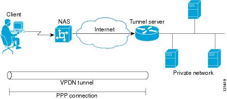
Figure 16 depicts a generic client-initiated VPDN tunneling scenario. The local device, which can be either a client PC or a client router, connects to the NAS through a medium that supports PPP. The client may initiate a VPDN tunnel to the tunnel server using either the PPTP, L2TP, or L2TPv3 protocol. The type of Layer 2 tunnel that is established is dependent on the configuration of both the client device and remote tunnel server.
Figure 16 Client-Initiated Tunneling
Client-Initiated VPDN Tunneling Using the L2TP or L2TPv3 Protocol
Client-initiated tunnels using the L2TP or L2TPv3 protocol must be initiated by a router configured as the local peer. The L2TP and L2TPv3 protocols are not supported for client-initiated tunnels from a client PC.
In the client-initiated tunneling scenario depicted in Figure 16, the local peer connects to the NAS through a medium that supports PPP, such as a dialup modem, DSL, ISDN, or cable modem. The client may initiate a VPDN tunnel to the tunnel server using either the L2TP or L2TPv3 protocol. The type of Layer 2 tunnel that is established is dependent on the configuration of both the local peer and remote tunnel server.
Figure 17
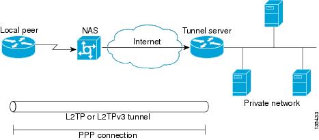
L2TP or L2TPv3 Client-Initiated Tunneling
Client-Initiated VPDN Tunneling Using the PPTP Protocol
Client-initiated tunnels using the PPTP protocol must be initiated by a client PC configured with appropriate VPN client software. The client must manage the software that initiates the tunnel on the PC. The PPTP protocol is not supported for client-initiated tunnels from a local peer router.
In the client-initiated tunneling scenario depicted in Figure 16, the client PC connects to the NAS through a medium that supports PPP, such as a dialup modem, DSL, ISDN, or cable modem. The client may initiate a VPDN tunnel to the tunnel server using the PPTP protocol.
Figure 18 PPTP Client-Initiated Tunneling

How to Configure Client-Initiated VPDN Tunneling
Perform one of the following procedures to configure client-initiated VPDN tunneling:
•
•
Configuring Client-Initiated Tunneling Using the L2TP or L2TPv3 Protocol
Support for client-initiated tunneling using the L2TP or L2TPv3 protocol was introduced in Cisco IOS Release 12.3(2)T. The type of tunnel that is established is dependent on the configuration of both the local and remote peers. The local and remote peers must be configured to establish the same type of tunnel.
L2TP or L2TPv3 client-initiated tunnels use a virtual-PPP interface. The virtual-PPP interface adds Layer 2 encapsulation to Layer 3 packets, allowing them to be sent to the tunnel server over an L2TP or L2TPv3 tunnel.
Perform the following tasks to configure client-initiated VPDN tunneling using L2TP or L2TPv3:
•
•
•
•
•
Prerequisites
•
•
•
Restrictions
•
•
•
•
•
Configuring L2TP or L2TPv3 Client-Initiated VPDN Tunneling on the Local Peer
Perform this task to configure the local peer to initiate VPDN tunnels to the tunnel server. This task applies to both L2TP and L2TPv3 configurations.
SUMMARY STEPS
1.
2.
3.
4.
5.
6.
7.
8.
9.
10.
11.
12.
13.
DETAILED STEPS
Step 1
enable
Example:Router> enable
Enables privileged EXEC mode.
•
Step 2
configure terminal
Example:Router# configure terminal
Enters global configuration mode.
Step 3
l2tp-class [l2tp-class-name]
Example:Router(config)# l2tp-class l2tpclass2
Specifies the L2TP class name and enters L2TP class configuration mode.
•
•
Step 4
exit
Example:Router(config-l2tp-class)# exit
Exits L2TP class configuration mode.
Step 5
pseudowire-class [pw-class-name]
Example:Router(config)# pseudowire-class pwclass2
Enters pseudowire class configuration mode and optionally specifies the name of the L2TP pseudowire class.
•
Step 6
exit
Example:Router(config-pw)# exit
Exits pseudowire class configuration mode.
Step 7
interface virtual-ppp number
Example:Router(config)# interface virtual-ppp 2
Enters interface configuration mode and assigns a virtual-PPP interface number.
Step 8
ip unnumbered interface-type interface-number
Example:Router(config-if)# ip unnumbered loopback 1
Enables IP processing on an interface without assigning an explicit IP address to the interface.
Step 9
ppp authentication protocol1 [protocol2...] [if-needed] [list-name | default] [callin] [one-time]
Example:Router(config-if)# ppp authentication chap
Enables Challenge Handshake Authentication Protocol (CHAP) or Password Authentication Protocol (PAP) or both and specifies the order in which CHAP and PAP authentication is selected on the interface.
Step 10
ppp chap hostname [hostname]
Example:Router(config-if)# ppp chap hostname peer2
Creates a pool of dialup routers that all appear to be the same host when authenticating with CHAP.
Step 11
pseudowire peer-ip-address vcid pw-class pw-class-name [sequencing {transmit | receive | both}]
Example:Router(config-if)# pseudowire 172.16.32.24 10 pw-class pwclass2
Specifies the IP address of the tunnel server and the 32-bit virtual circuit identifier (VCID) shared between the devices at each end of the control channel.
•
Note
•
•
Note
Step 12
exit
Example:Router(config-if)# exit
Exits interface configuration mode.
Step 13
ip route prefix mask {ip-address | interface-type interface-number [ip-address]} [distance] [name] [permanent] [tag tag]
Example:Router(config)# ip route 10.20.20.0 255.255.255.0 virtual-PPP 1
Establishes static routes.
What to Do Next
You must perform one of the following tasks depending on the tunneling protocol you are configuring:
•
•
Configuring Client-Initiated Tunneling on the Tunnel Server for L2TP Tunnels
The tunnel server must be configured to terminate VPDN tunnels. The same tunneling protocol must be configured on the tunnel server and the local peer device. For L2TP tunnels, the tunneling protocol is configured in a VPDN group on the tunnel server. On the local peer, the tunneling protocol is configured in a pseudowire class.
When a request to establish an L2TP tunnel is received by the tunnel server, the tunnel server must create a virtual access interface. The virtual access interface is cloned from a virtual template interface, used, and then freed when no longer needed. The virtual template interface is a logical entity that is not tied to any physical interface.
Perform this task to configure the tunnel server to terminate client-initiated L2TP tunnels and to configure a basic virtual template. For more detailed information about all of the configuration options available for a virtual template, see the "Configuring Virtual Template Interfaces" section of the Cisco IOS Dial Technologies Configuration Guide, Release 12.4.
Prerequisites
You must perform the required tasks in the "Configuring AAA for VPDNs" module.
SUMMARY STEPS
1.
2.
3.
4.
5.
6.
7.
8.
9.
10.
11.
12.
13.
14.
DETAILED STEPS
What to Do Next
•
•
Configuring Client-Initiated Tunneling on the Tunnel Server for L2TPv3 Tunnels
The tunnel server must be configured to terminate VPDN tunnels. The same tunneling protocol must be configured on the tunnel server and the local peer device. For L2TPv3 tunnels, the tunneling protocol is configured in a pseudowire class on both the tunnel server and the local peer.
Perform this task to configure the tunnel server to terminate client-initiated L2TPv3 tunnels.
SUMMARY STEPS
1.
2.
3.
4.
5.
6.
7.
8.
9.
10.
11.
12.
13.
DETAILED STEPS
Step 1
enable
Example:Router> enable
Enables privileged EXEC mode.
•
Step 2
configure terminal
Example:Router# configure terminal
Enters global configuration mode.
Step 3
l2tp-class [l2tp-class-name]
Example:Router(config)# l2tp-class l2tpclass2
Specifies the L2TP class name and enters L2TP class configuration mode.
•
•
Step 4
exit
Example:Router(config-l2tp-class)# exit
Exits L2TP class configuration mode.
Step 5
pseudowire-class [pw-class-name]
Example:Router(config)# pseudowire-class pwclass2
Enters pseudowire class configuration mode and optionally specifies the name of the L2TP pseudowire class.
•
Step 6
exit
Example:Router(config-pw)# exit
Exits pseudowire class configuration mode.
Step 7
interface virtual-ppp number
Example:Router(config)# interface virtual-ppp 2
Enters interface configuration mode and assigns a virtual-PPP interface number.
Step 8
ip unnumbered interface-type interface-number
Example:Router(config-if)# ip unnumbered loopback 1
Enables IP processing on an interface without assigning an explicit IP address to the interface.
Step 9
ppp authentication protocol1 [protocol2...] [if-needed] [list-name | default] [callin] [one-time]
Example:Router(config-if)# ppp authentication chap
Enables CHAP or PAP or both and specifies the order in which CHAP and PAP authentication is selected on the interface.
Step 10
ppp chap hostname [hostname]
Example:Router(config-if)# ppp chap hostname peer2
Creates a pool of dialup routers that all appear to be the same host when authenticating with CHAP.
Step 11
pseudowire peer-ip-address vcid pw-class pw-class-name [sequencing {transmit | receive | both}]
Example:Router(config-if)# pseudowire 172.16.32.24 10 pw-class pwclass2
Specifies the IP address of the local peer and the 32-bit VCID shared between the local peer and the tunnel server.
•
Note
•
•
Note
Step 12
exit
Example:Router(config-if)# exit
Exits interface configuration mode.
Step 13
ip route prefix mask {ip-address | interface-type interface-number [ip-address]} [distance] [name] [permanent] [tag tag]
Example:Router(config)# ip route 10.20.20.0 255.255.255.0 Virtual-PPP 1
Establishes static routes.
What to Do Next
•
•
Configuring L2TP Control Channel Parameters
The L2TP class configuration procedure creates a template of L2TP control channel parameters that can be inherited by different pseudowire classes. L2TP control channel parameters are used in control channel authentication, keepalive messages, and control channel negotiation. Configuring L2TP control channel parameters is optional.
For L2TP, the L2TP class is configured only on the local peer. An L2TP class was defined for the local peer in the task "Configuring L2TP or L2TPv3 Client-Initiated VPDN Tunneling on the Local Peer."
For L2TPv3, an L2TP class must be configured on both the local peer and the tunnel server. An L2TP class was defined for the local peer in the task "Configuring L2TP or L2TPv3 Client-Initiated VPDN Tunneling on the Local Peer." An L2TP class was defined for the tunnel server in the task "Configuring Client-Initiated Tunneling on the Tunnel Server for L2TPv3 Tunnels."
The three groups of L2TP control channel parameters that you can configure for an L2TP class are described in the following sections:
•
•
•
After the router enters L2TP class configuration mode, you can configure L2TP control channel parameters in any order. If you have multiple authentication requirements you can configure multiple sets of L2TP class control channel parameters with different L2TP class names. However, only one set of L2TP class control channel parameters can be applied to a connection between any pair of IP addresses.
Prerequisites
The following configuration tasks must be completed before configuring L2TP control channel parameters:
L2TP Tunnels
•
L2TPv3 Tunnels
•
•
Configuring L2TP Control Channel Timing Parameters
The following L2TP control channel timing parameters can be configured in L2TP class configuration mode:
•
•
•
Perform this task to configure a set of timing control channel parameters for an L2TP class. All of the timing control channel parameter configurations are optional and may be configured in any order. If these parameters are not configured, the default values are applied.
SUMMARY STEPS
1.
2.
3.
4.
5.
6.
DETAILED STEPS
What to Do Next
•
•
•
Configuring L2TP Control Channel Authentication Parameters
The following L2TP control channel authentication parameters can be configured in L2TP class configuration mode:
•
•
•
•
Perform this task to configure a set of authentication control channel parameters for an L2TP class. All of the authentication control channel parameter configurations are optional and may be configured in any order. If these parameters are not configured, the default values will be applied.
SUMMARY STEPS
1.
2.
3.
4.
5.
6.
7.
DETAILED STEPS
What to Do Next
•
•
Configuring L2TP Control Channel Maintenance Parameters
The L2TP hello packet keepalive interval control channel maintenance parameter can be configured in L2TP class configuration mode.
Perform this task to configure the interval used for hello messages for an L2TP class. This control channel parameter configuration is optional. If this parameter is not configured, the default value will be applied.
SUMMARY STEPS
1.
2.
3.
4.
DETAILED STEPS
What to Do Next
You must perform the task in the "Configuring the Pseudowire" section.
Configuring the Pseudowire
The pseudowire class configuration procedure creates a configuration template for the pseudowire. You use this template, or class, to configure session-level parameters for L2TP or L2TPv3 sessions that will be used to transport attachment circuit traffic over the pseudowire.
The pseudowire configuration specifies the characteristics of the L2TP or L2TPv3 signaling mechanism, including the data encapsulation type, the control protocol, sequencing, fragmentation, payload-specific options, and IP properties. The setting that determines if signaling is used to set up the pseudowire is also included.
For L2TP, the pseudowire class is configured only on the local peer. A pseudowire class was defined for the local peer in the task "Configuring L2TP or L2TPv3 Client-Initiated VPDN Tunneling on the Local Peer."
For L2TPv3, the pseudowire class must be configured on both the local peer and the tunnel server. A pseudowire class was defined for the local peer in the task "Configuring L2TP or L2TPv3 Client-Initiated VPDN Tunneling on the Local Peer." A pseudowire class was defined for the tunnel server in the task "Configuring Client-Initiated Tunneling on the Tunnel Server for L2TPv3 Tunnels."
Specifying a source IP address to configure a loopback interface is highly recommended. If you do not configure a loopback interface, the router will choose the best available local address. This configuration could prevent a control channel from being established.
If you do not configure the optional pseudowire class configuration commands, the default values are used.
Prerequisites
The following configuration tasks must be completed before configuring the pseudowire:
L2TP Tunnels
•
L2TPv3 Tunnels
•
•
SUMMARY STEPS
1.
2.
3.
4.
5.
6.
7.
8.
9.
10.
11.
DETAILED STEPS
What to Do Next
•
•
Verifying an L2TP Control Channel
Perform this task to display detailed information about the L2TP control channels that are set up to other L2TP-enabled devices for all L2TP sessions on the router.
SUMMARY STEPS
1.
2.
DETAILED STEPS
What to Do Next
You may perform any of the relevant optional tasks in the "Configuring Additional VPDN Features" and "VPDN Tunnel Management" modules.
Configuring Client-Initiated VPDN Tunneling Using the PPTP Protocol
Client-initiated tunnels using the PPTP protocol must be initiated by a client PC configured with appropriate VPN client software. The client must manage the software that initiates the tunnel on their PC. The PPTP protocol is not supported for client-initiated tunnels initiated by a router.
PPTP uses an enhanced Generic Routing Encapsulation (GRE) mechanism to provide a flow- and congestion-controlled encapsulated datagram service for carrying PPP packets.
The following sections contain information about PPTP features:
•
•
•
Perform the tasks in the following sections to configure client-initiated VPDN tunneling using the PPTP protocol:
•
•
•
•
MPPE Encryption of PPTP Tunnels
Microsoft Point-to-Point Encryption (MPPE) can be used to encrypt PPTP VPDN tunnels. MPPE encrypts the entire session from the client to the tunnel server.
MPPE is an encryption technology developed by Microsoft to encrypt point-to-point links. These connections can be over a dialup line or over a VPDN tunnel. MPPE works is a feature of Microsoft Point-to-Point Compression (MPPC).
MPPC is a scheme used to compress PPP packets between Cisco and Microsoft client devices. The MPPC algorithm is designed to optimize bandwidth utilization in order to support multiple simultaneous connections.
MPPE is negotiated using bits in the MPPC option within the Compression Control Protocol (CCP) MPPC configuration option (CCP configuration option number 18).
MPPE uses the RC4 algorithm with either 40- or 128-bit keys. All keys are derived from the cleartext authentication password of the user. RC4 is stream cipher; therefore, the sizes of the encrypted and decrypted frames are the same size as the original frame. The Cisco implementation of MPPE is fully interoperable with that of Microsoft and uses all available options, including stateless mode (sometimes referred to as historyless mode). Stateless mode can increase throughput in lossy environments such as VPDNs, because neither side needs to send CCP Resets Requests to synchronize encryption contexts when packets are lost.
The following two modes of MPPE encryption are available:
Stateful MPPE Encryption
Stateful encryption provides the best performance but may be adversely affected by networks that experience substantial packet loss. Because of the way that the RC4 tables are reinitialized during stateful synchronization, it is possible that two packets may be encrypted using the same key. For this reason, stateful encryption may not be appropriate for lossy network environments (such as Layer 2 tunnels on the Internet). If you configure stateful encryption, the PPTP flow control alarm is automatically enabled.
Stateless MPPE Encryption
Stateless encryption provides a lower level of performance, but will be more reliable in a lossy network environment. Stateless mode is sometimes referred to as historyless mode. The PPTP flow control alarm is automatically disabled when stateless encryption is being used.
PPTP Flow Control Alarm
The PPTP flow control alarm indicates when congestion or lost packets are detected. When the flow control alarm goes off, PPTP reduces volatility and additional control traffic by falling back from a stateful to a stateless encryption mode for the MPPE session.
Prerequisites for Configuring Client-Initiated VPDN Tunneling Using the PPTP Protocol
The client PC must be configured with appropriate VPN client software.
Restrictions for Configuring Client-Initiated VPDN Tunneling Using the PPTP Protocol
•
•
•
•
•
•
•
•
Configuring the Tunnel Server to Accept PPTP Tunnels
The tunnel server must be configured to terminate PPTP tunnels.
Perform this task to configure the tunnel server to accept tunneled PPPTP connections from a client.
SUMMARY STEPS
1.
2.
3.
4.
5.
6.
DETAILED STEPS
What to Do Next
You must perform the task in the "Configuring the Virtual Template on the Tunnel Server" section.
Configuring the Virtual Template on the Tunnel Server
When a request to establish a tunnel is received by the tunnel server, the tunnel server must create a virtual access interface. The virtual access interface is cloned from a virtual template interface, used, and then freed when no longer needed. The virtual template interface is a logical entity that is not tied to any physical interface.
Perform this task on the tunnel server to configure a basic virtual template. For more detailed information about all of the configuration options available for a virtual template, see the "Configuring Virtual Template Interfaces" section of the Cisco IOS Dial Technologies Configuration Guide, Release 12.4.
SUMMARY STEPS
1.
2.
3.
4.
5.
6.
7.
8.
DETAILED STEPS
What to Do Next
•
•
Configuring MPPE on the ISA Card
Using the Industry-Standard Architecture (ISA) card to offload MPPE from the Route Processor will improve performance in large-scale environments.
Perform this optional task to offload MPPE encryption from the tunnel server processor to the ISA card.
Restrictions
An ISA card must be installed on the tunnel server.
SUMMARY STEPS
1.
2.
3.
4.
DETAILED STEPS
What to Do Next
•
•
•
Tuning PPTP
You can configure PPTP control options to tune the performance of your PPTP deployment. All of the PPTP tuning configuration commands are optional and may be configured in any order. If these parameters are not configured, the default values are applied.
Perform this task to tune PPTP control options.
SUMMARY STEPS
1.
2.
3.
4.
5.
6.
DETAILED STEPS
What to Do Next
•
•
Verifying a PPTP Client-Initiated VPDN Configuration
Perform this task to verify that a PPTP client-initiated VPDN configuration functions properly.
SUMMARY STEPS
1.
2.
3.
4.
5.
6.
7.
DETAILED STEPS
Step 1
Ensure that the client PC is able to connect to the NAS by establishing a dial-in connection. As the call comes in to the NAS, a LINK-3-UPDOWN message automatically appears on the NAS terminal screen. In the following example, the call comes into the NAS on asynchronous interface 14:
*Jan 1 21:22:18.410: %LINK-3-UPDOWN: Interface Async14, changed state to up
Note
If this message is not displayed by the NAS, there is a problem with the dial-in configuration. For more information about configuring and troubleshooting dial-in connections, see the Cisco IOS Dial Technologies Configuration Guide, Release 12.4.
Step 2
Step 3
From the client desktop:
a.
b.
c.
d.
e.
Step 4
Enter this command on the tunnel server to enter privileged EXEC mode. Enter your password if prompted:
Router> enableStep 5
Enter this command on the tunnel server to display information about active tunnels and message identifiers. Verify that the client has established a PPTP session.
Router# show vpdn% No active L2TP tunnels% No active L2F tunnelsPPTP Tunnel and Session Information (Total tunnels=1 sessions=1)LocID RemID Remote Name State Remote Address Port Sessions13 13 10.1.2.41 estabd 10.1.2.41 1136 1LocID RemID TunID Intf Username State Last Chg13 0 13 Vi3 estabd 000030Step 6
Enter this command for more detailed information about the VPDN session. The last line of output from the show vpdn session all command indicates the current status of the flow control alarm.
Router# show vpdn session all% No active L2TP tunnels% No active L2F tunnelsPPTP Session Information (Total tunnels=1 sessions=1)Call id 13 is up on tunnel id 13Remote tunnel name is 10.1.2.41Internet Address is 10.1.2.41Session username is unknown, state is estabdTime since change 000106, interface Vi3Remote call id is 010 packets sent, 10 received, 332 bytes sent, 448 receivedSs 11, Sr 10, Remote Nr 10, peer RWS 160 out of order packetsFlow alarm is clear.Step 7
Enter this command to display MPPE information for the virtual access interface:
Router# show ppp mppe virtual-access 3Interface Virtual-Access3 (current connection)Hardware (ISA5/1, flow_id=13) encryption, 40 bit encryption, Stateless modepackets encrypted = 0 packets decrypted = 1sent CCP resets = 0 receive CCP resets = 0next tx coherency = 0 next rx coherency = 0tx key changes = 0 rx key changes = 0rx pkt dropped = 0 rx out of order pkt= 0rx missed packets = 0To display changed information, reissue the command:
Router# show ppp mppe virtual-access 3Interface Virtual-Access3 (current connection)Hardware (ISA5/1, flow_id=13) encryption, 40 bit encryption, Stateless modepackets encrypted = 0 packets decrypted = 1sent CCP resets = 0 receive CCP resets = 0next tx coherency = 0 next rx coherency = 0tx key changes = 0 rx key changes = 1rx pkt dropped = 0 rx out of order pkt= 0rx missed packets = 0
Configuration Examples for Client-Initiated VPDN Tunneling
This section contains the following configuration examples:
•
•
•
•
Configuring L2TP Client-Initiated Tunneling: Example
The following example configures L2TP client-initiated tunneling on the local peer and the tunnel server. This configuration is for L2TP tunnels.
Local Peer Configuration
l2tp-class l2tpclass1!pseudowire-class pwclass1encapsulation l2tpv2protocol l2tpv2 l2tpclass1ip local interface ethernet0/0!interface virtual-ppp 1ip unnumbered loopback1ppp authentication chapppp chap hostname peer1pseudowire 172.24.13.196 10 pw-class pwclass1!ip route 10.10.10.0 255.255.255.0 virtual-PPP 1Tunnel Server Configuration
vpdn-group l2tpgroup1accept-dialinprotocol l2tpvirtual-template 1terminate-from hostname peer1!interface virtual-template 1ip unnumbered loopback 1ppp authentication chapppp chap hostname peer2Configuring L2TPv3 Client-Initiated Tunneling: Example
The following example configures L2TP client-initiated tunneling on the local peer and tunnel server. This configuration is for L2TPv3 tunnels.
Local Peer Configuration
l2tp-class l2tpclass1!pseudowire-class pwclass1encapsulation l2tpv3protocol l2tpv3 l2tpclass1ip local interface ethernet0/0!interface virtual-ppp 1ip unnumbered loopback1ppp authentication chapppp chap hostname peer1pseudowire 172.24.13.196 15 pw-class pwclass1!ip route 10.10.10.0 255.255.255.0 virtual-PPP 1Tunnel Server Configuration
l2tp-class l2tpclass2!pseudowire-class pwclass2encapsulation l2tpv3protocol l2tpv3 l2tpclass2ip local interface ethernet0/1!interface virtual-ppp 2ip unnumbered loopback 1ppp authentication chapppp chap hostname peer2pseudowire 172.16.32.24 15 pw-class pwclass2!ip route 10.20.20.0 255.255.255.0 virtual-PPP 1Verifying an L2TP Control Channel: Example
The following output displays detailed information the L2TP control channels that are set up to other L2TP-enabled devices for all L2TP sessions on the router:
Router# show l2tun session allSession Information Total tunnels 0 sessions 1Session id 111 is up, tunnel id 0Call serial number is 0Remote tunnel name isInternet address is 2.0.0.1Session is manually signalledSession state is established, time since change 00:06:050 Packets sent, 0 received0 Bytes sent, 0 receivedReceive packets dropped:out-of-order: 0total: 0Send packets dropped:exceeded session MTU: 0total: 0Session vcid is 123Session Layer 2 circuit, type is ATM VPC CELL, name is ATM3/0/0:1000007Circuit state is UPRemote session id is 222, remote tunnel id 0DF bit off, ToS reflect disabled, ToS value 0, TTL value 255Session cookie information:local cookie, size 8 bytes, value 00 00 00 00 00 00 00 64remote cookie, size 8 bytes, value 00 00 00 00 00 00 00 C8SSS switching enabledSequencing is offConfiguring Client-Initiated VPDN Tunneling Using PPTP: Example
The following example shows the configuration of a tunnel server for client-initiated VPDN tunneling with the PPTP protocol using an ISA card to perform stateless MPPE encryption:
vpdn-group pptp1accept-dialinprotocol pptpvirtual-template 1local name cisco_pns!interface virtual-template 1ip unnumbered FastEthernet 0/0peer default ip address pool mypoolencapsulation pppppp authentication ms-chapppp encrypt mppe auto!controller ISA 5/0encryption mppeWhere to Go Next
You may perform any of the relevant optional tasks in the "Configuring Additional VPDN Features" and "VPDN Tunnel Management" modules.
Additional References
The following sections provide references related to client-initiated dial-in VPDN tunneling.
Related Documents
VPDN technology overview
VPDN commands: complete command syntax, command mode, defaults, usage guidelines, and examples
Cisco IOS VPDN Command Reference, Release 12.4T
Information on configuring a PPP connection between the NAS and the tunnel server
"PPP Configuration" part of the Cisco IOS Dial Technologies Configuration Guide, Release 12.4
Information about configuring the NAS to accept dialin connections from the client
Cisco IOS Dial Technologies Configuration Guide, Release 12.4
Information about virtual templates
"Configuring Virtual Template Interfaces" chapter of the Cisco IOS Dial Technologies Configuration Guide, Release 12.4
Dial Technologies commands: complete command syntax, command mode, defaults, usage guidelines, and examples
Cisco IOS Dial Technologies Command Reference, Release 12.4T
Information about configuring the NAS to accept broadband connections from the client
Cisco IOS Broadband and DSL Configuration Guide, Release 12.4
Technical support documentation for L2TP
Technical support documentation for PPTP
Technical support documentation for VPDNs
Standards
MIBs
RFCs
RFC 2637
Point-to-Point Tunneling Protocol (PPTP)
RFC 2661
Layer Two Tunneling Protocol "L2TP"
RFC 3931
Layer Two Tunneling Protocol - Version 3 (L2TPv3)
Technical Assistance
Feature Information for Client-Initiated VPDN Tunneling
Table 6 lists the features in this module and provides links to specific configuration information. Only features that were introduced or modified in Cisco IOS Release 12.2(1) or a later release appear in the table.
Not all commands may be available in your Cisco IOS software release. For details on when support for a specific command was introduced, see the command reference documentation.
For information on a feature in this technology that is not documented here, see the "VPDN Features Roadmap."
Cisco IOS software images are specific to a Cisco IOS software release, a feature set, and a platform. Use Cisco Feature Navigator to find information about platform support and Cisco IOS software image support. Access Cisco Feature Navigator at http://www.cisco.com/go/fn. You must have an account on Cisco.com. If you do not have an account or have forgotten your username or password, click Cancel at the login dialog box and follow the instructions that appear.
Note
Table 6 Feature Information for Client-Initiated VPDN Tunneling
L2TP Client-Initiated Tunneling
12.3(2)T
This feature introduces the ability to establish client-initiated L2TP tunnels. The client may initiate an L2TP or L2TPv3 tunnel to the tunnel server without the intermediate NAS participating in tunnel negotiation or establishment.
The following sections provide information about this feature:
•
•
The following commands were introduced or modified by this feature: authentication (L2TP), encapsulation (L2TP), hello, hidden, hostname (L2TP), interface virtual-ppp, ip dfbit set, ip local interface, ip pmtu, ip protocol, ip tos (L2TP), ip ttl, l2tp-class, password (L2TP), protocol (L2TP), pseudowire, pseudowire-class, receive-window, retransmit, sequencing, timeout setup.

© 2006 Cisco Systems, Inc. All rights reserved.
This module first published October 31, 2005. Last updated October 31, 2005.