Configuring DHCP

This chapter describes how to configure the Dynamic Host Configuration Protocol (DHCP) on a Cisco NX-OS device.

This chapter includes the following sections:

About DHCP Snooping

DHCP snooping is a security feature that acts as a firewall between untrusted hosts and trusted DHCP servers.

  • Validates DHCP messages received from untrusted sources and filters out invalid messages.

  • Builds and maintains the DHCP snooping binding database, which contains information about untrusted hosts with leased IP addresses.

  • Uses the DHCP snooping binding database to validate subsequent requests from untrusted hosts.

Enabling and Scope of DHCP Snooping

DHCP snooping can be enabled globally and on a per-VLAN basis. By default, the feature is disabled globally and on all VLANs. You can enable the feature on a single VLAN or a range of VLANs.

Trusted and Untrusted Sources

You can configure whether DHCP snooping trusts traffic sources. An untrusted source may initiate traffic attacks or other hostile actions. To prevent such attacks, DHCP snooping filters messages from untrusted sources.

In an enterprise network, a trusted source is a device that is under your administrative control. These devices include the switches, routers, and servers in the network. Any device beyond the firewall or outside the network is an untrusted source. Generally, host ports are treated as untrusted sources.

In a service provider environment, any device that is not in the service provider network is an untrusted source (such as a customer switch). Host ports are untrusted sources.

In the Cisco NX-OS device, you indicate that a source is trusted by configuring the trust state of its connecting interface.

The default trust state of all interfaces is untrusted. You must configure DHCP server interfaces as trusted. You can also configure other interfaces as trusted if they connect to devices (such as switches or routers) inside your network. You usually do not configure host port interfaces as trusted.


Note


For DHCP snooping to function properly, all DHCP servers must be connected to the device through trusted interfaces.


DHCP Snooping Binding Database

Using information extracted from intercepted DHCP messages, DHCP snooping dynamically builds and maintains a database. The database contains an entry for each untrusted host with a leased IP address if the host is associated with a VLAN that has DHCP snooping enabled. The database does not contain entries for hosts connected through trusted interfaces.


Note


The DHCP snooping binding database is also referred to as the DHCP snooping binding table.


DHCP snooping updates the database when the device receives specific DHCP messages. For example, the feature adds an entry to the database when the device receives a DHCPACK message from the server. The feature removes the entry in the database when the IP address lease expires or the device receives a DHCPRELEASE message from the host.

Each entry in the DHCP snooping binding database includes the MAC address of the host, the leased IP address, the lease time, the binding type, and the VLAN number and interface information associated with the host.

Dynamic ARP inspection (DAI) and IP Source Guard also use information stored in the DHCP snooping binding database.

You can remove entries from the binding database by using the clear ip dhcp snooping binding command.

DHCP Snooping in a vPC Environment

A virtual port channel (vPC) allows two Cisco NX-OS switches to appear as a single logical port channel to a third device. The third device can be a switch, a server, or any other networking device that supports port channels.

In a typical vPC environment, DHCP requests can reach one vPC peer switch, and the responses can reach the other vPC peer switch, resulting in a partial DHCP (IP-MAC) binding entry in one switch and no binding entry in the other switch. As a result, DHCP snooping and associated features such as dynamic ARP inspection (DAI) and IP Source Guard are disrupted. This issue is addressed by using Cisco Fabric Service over Ethernet (CFSoE) distribution to ensure that all DHCP packets (requests and responses) appear on both switches, which helps in creating and maintaining the same binding entry on both switches for all clients behind the vPC link.

CFSoE distribution also allows only one switch to forward the DHCP requests and responses on the vPC link. In non-vPC environments, both switches forward the DHCP packets.

Synchronizing DHCP Snooping Binding Entries

The dynamic DHCP binding entries should be synchronized in the following scenarios:
  • When the remote vPC is online, all the binding entries for that vPC link should be synchronized with the peer.

  • When DHCP snooping is enabled on the peer switch, the dynamic binding entries for all vPC links should be synchronized with the peer.

Packet Validation

The device validates DHCP packets received on the untrusted interfaces of VLANs that have DHCP snooping enabled. The device forwards the DHCP packet unless any of the following conditions occur (in which case, the packet is dropped):

  • The device receives a DHCP response packet (such as a DHCPACK, DHCPNAK, or DHCPOFFER packet) on an untrusted interface.

  • The device receives a packet on an untrusted interface, and the source MAC address and the DHCP client hardware address do not match. This check is performed only if the DHCP snooping MAC address verification option is turned on.

  • The device receives a DHCPRELEASE or DHCPDECLINE message from an untrusted host with an entry in the DHCP snooping binding table, and the interface information in the binding table does not match the interface on which the message was received.

In addition, you can enable strict validation of DHCP packets, which checks the options field of DHCP packets, including the “magic cookie” value in the first four bytes of the options field. By default, strict validation is disabled. When you enable it, by using the ip dhcp packet strict-validation command, if DHCP snooping processes a packet that has an invalid options field, it drops the packet.

DHCP Snooping Option 82 Data Insertion

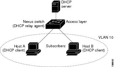
DHCP can centrally manage the IP address assignments for a large number of subscribers. When you enable Option 82, the device identifies a subscriber device that connects to the network (in addition to its MAC address). Multiple hosts on the subscriber LAN can connect to the same port on the access device and are uniquely identified.

When you enable Option 82 on the Cisco NX-OS device, the following sequence of events occurs:

  1. The host (DHCP client) generates a DHCP request and broadcasts it on the network.

  2. When the Cisco NX-OS device receives the DHCP request, it adds the Option 82 information in the packet. The Option 82 information contains the device MAC address (the remote ID suboption) and the port identifier vlan-ifindex (for non-vPCs) or vlan-vpcid (for vPCs), from which the packet is received (the circuit ID suboption).


    Note


    For vPC peer switches, the remote ID suboption contains the vPC switch MAC address, which is unique in both switches. This MAC address is computed with the vPC domain ID. The Option 82 information is inserted at the switch where the DHCP request is first received before it is forwarded to the other vPC peer switch.


  3. The device forwards the DHCP request that includes the Option 82 field to the DHCP server.

  4. The DHCP server receives the packet. If the server is Option 82 capable, it can use the remote ID, the circuit ID, or both to assign IP addresses and implement policies, such as restricting the number of IP addresses that can be assigned to a single remote ID or circuit ID. The DHCP server echoes the Option 82 field in the DHCP reply.

  5. The DHCP server sends the reply to the Cisco NX-OS device. The Cisco NX-OS device verifies that it originally inserted the Option 82 data by inspecting the remote ID and possibly the circuit ID fields. The Cisco NX-OS device removes the Option 82 field and forwards the packet to the interface that connects to the DHCP client that sent the DHCP request.

If the previously described sequence of events occurs, the following values do not change:

  • Circuit ID suboption fields

    • Suboption type

    • Length of the suboption type

    • Circuit ID type

    • Length of the circuit ID type

  • Remote ID suboption fields

    • Suboption type

    • Length of the suboption type

    • Remote ID type

    • Length of the circuit ID type

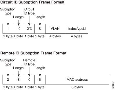
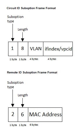
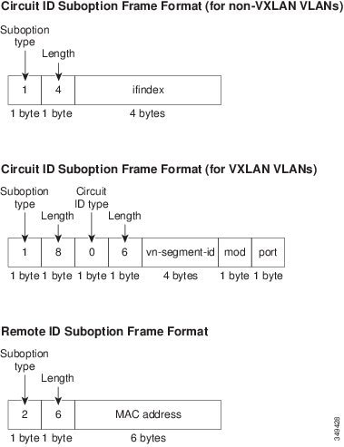
This figure shows the packet formats for the remote ID suboption and the circuit ID suboption. The Cisco NX-OS device uses the packet formats when you globally enable DHCP snooping and when you enable Option 82 data insertion and removal. For the circuit ID suboption, the module field is the slot number of the module.

Figure 1. Suboption Packet Formats
Figure 2. Suboption Packet Format (Non TLV format)

About the DHCP Relay Agent

DHCP Relay Agent

The DHCP relay agent is a network device feature that forwards DHCP packets between clients and servers located on different subnets.

  • Receives DHCP messages from clients and generates new DHCP messages to send on another interface.

  • Sets the gateway address (giaddr field) in the DHCP packet and can add Option 82 (relay agent information option) if configured.

  • Forwards replies from the DHCP server back to the client, removing Option 82 if present.

DHCP Relay Agent Reference Information

The DHCP relay agent is useful when DHCP clients and servers are not on the same physical subnet.


Note


When the device relays a DHCP request that already includes Option 82 information, the device forwards the request with the original Option 82 information without altering it.


DHCP Relay Agent Option 82

The DHCP relay agent Option 82 is a feature that enables a device to insert and remove Option 82 information in DHCP packets forwarded by the relay agent.

  • Allows insertion of Option 82 information, including device MAC address (remote ID) and port identifier (circuit ID), into DHCP packets.

  • Enables DHCP servers to use Option 82 data for IP address assignment and policy enforcement.

  • Facilitates communication between DHCP clients and servers on different subnets by relaying and modifying DHCP messages.

How DHCP Relay Agent Option 82 Works

DHCP relay agent Option 82 enhances DHCP message exchange by appending identifying information to requests and managing packet forwarding between clients and servers on separate subnets.

  1. The host (DHCP client) generates a DHCP request and broadcasts it on the network.

  2. When the Cisco NX-OS device receives the DHCP request, it adds the Option 82 information in the packet. The Option 82 information contains the device MAC address (the remote ID suboption) and the port identifier ifindex (for non-VXLAN VLANs) or vn-segment-id-mod-port (for VXLAN VLANs), from which the packet is received (the circuit ID suboption). In DHCP relay, the circuit ID is filled with the ifindex of the SVI or Layer 3 interface on which DHCP relay is configured.

  3. The device adds the IP address of the relay agent to the DHCP packet.

  4. The device forwards the DHCP request that includes the Option 82 field to the DHCP server.

  5. The DHCP server receives the packet. If the server is Option 82 capable, it can use the remote ID, the circuit ID, or both to assign IP addresses and implement policies, such as restricting the number of IP addresses that can be assigned to a single remote ID or circuit ID. The DHCP server echoes the Option 82 field in the DHCP reply.

  6. The DHCP server unicasts the reply to the Cisco NX-OS device if the request was relayed to the server by the device. The Cisco NX-OS device verifies that it originally inserted the Option 82 data by inspecting the remote ID and possibly the circuit ID fields. The Cisco NX-OS device removes the Option 82 field and forwards the packet to the interface that connects to the DHCP client that sent the DHCP request.

This figure shows an example of a metropolitan Ethernet network in which a centralized DHCP server assigns IP addresses to subscribers connected to the device at the access layer. Because the DHCP clients and their associated DHCP server do not reside on the same IP network or subnet, a DHCP relay agent is configured with a helper address to enable broadcast forwarding and to transfer DHCP messages between the clients and the server.

Figure 3. DHCP Relay Agent in a Metropolitan Ethernet Network

This figure shows the packet formats for the circuit ID suboption and the remote ID suboption.

Figure 4. Suboption Packet Formats

Example: DHCP Relay Agent Option 82 in Action

For example, in a metropolitan Ethernet network, a DHCP relay agent configured on a Cisco NX-OS device inserts Option 82 information into DHCP requests from clients. The DHCP server uses this information to assign IP addresses and enforce policies, then the relay agent removes the Option 82 data before forwarding the reply to the client.

VRF Support for the DHCP Relay Agent

The VRF support for the DHCP relay agent allows DHCP broadcast messages from clients in one VRF to be forwarded to DHCP servers in another VRF, enabling centralized DHCP support and efficient IP address utilization.

  • Enables a single DHCP server to serve clients across multiple VRFs using a shared IP address pool.

  • Requires Option 82 to be enabled for the DHCP relay agent.

  • Option 82 information includes VPN identifier, link selection, and server identifier override.

How VRF Support Works with the DHCP Relay Agent

You can configure the DHCP relay agent to forward DHCP broadcast messages from clients in a virtual routing and forwarding (VRF) instance to DHCP servers in a different VRF. By using a single DHCP server to provide DHCP support to clients in multiple VRFs, you can conserve IP addresses by using a single IP address pool rather than one for each VRF. For general information about VRFs, see the Cisco Nexus 9000 Series NX-OS Unicast Routing Configuration Guide .

  • DHCP relay agent forwards client messages between VRFs.

  • Centralized DHCP server supports multiple VRFs.

  • Option 82 must be enabled for VRF support.

  1. Enable Option 82 for the DHCP relay agent.

  2. Configure DHCP relay address and VRF information on the interface.

  3. Device inserts Option 82 information and forwards the request to the DHCP server in the server VRF.

  4. Device strips Option 82 from the response and forwards it to the client in the client VRF.

  • VPN identifier: Name of the VRF that the interface receiving the DHCP request is a member of.

  • Link selection: Subnet address of the interface receiving the DHCP request. When DHCP smart relay is enabled, this is the subnet of the active giaddr.

  • Server identifier override: IP address of the interface receiving the DHCP request. When DHCP smart relay is enabled, this is the active giaddr.


Note


The DHCP server must support the VPN identifier, link selection, and server identifier override options.


Example: VRF Support for DHCP Relay Agent

For example, if a DHCP request arrives on an interface configured with a DHCP relay address and VRF information, and the DHCP server address belongs to a network in a different VRF, the device inserts Option 82 information (including VPN identifier, link selection, and server identifier override) and forwards the request to the server in the server VRF. The response is then returned to the client in the client VRF after stripping Option 82.

DHCP Smart Relay Agent

The DHCP smart relay agent is a network component that forwards DHCP broadcast requests and manages IP address allocation from available subnet pools.

  • Forwards DHCP broadcast request packets from hosts to the DHCP server by setting the giaddr to the primary address of the inbound interface.

  • Allocates IP addresses from the primary subnet pool until it is exhausted.

  • Can be configured to allocate IP addresses from the secondary subnet pool if the primary pool is exhausted or ignored by the server.

Reference Information for DHCP Smart Relay Agent

The DHCP smart relay agent enhances address allocation flexibility, especially when the number of hosts exceeds the available addresses in the primary pool or when multiple subnets are configured on an interface.

Example of DHCP Smart Relay Agent Operation

For example, if a network interface has both primary and secondary IP subnets configured, and the primary subnet pool is exhausted, the DHCP smart relay agent can allocate addresses from the secondary subnet pool to accommodate additional hosts.

About the DHCPv6 Relay Agent

DHCPv6 Relay Agent

The DHCPv6 relay agent is a network function that forwards DHCPv6 packets between clients and servers when they are not on the same physical subnet.

  • Receives DHCPv6 messages from clients.

  • Generates new DHCPv6 messages to send out on another interface.

  • Sets the gateway address (giaddr field) and forwards messages to the DHCPv6 server.

Supporting reference information for DHCPv6 Relay Agent

The DHCPv6 relay agent is used when DHCPv6 clients and servers are located on different subnets, allowing communication between them.

VRF Support for the DHCPv6 Relay Agent

The DHCPv6 relay agent with VRF support enables forwarding of DHCPv6 broadcast messages from clients in one VRF instance to DHCPv6 servers in another VRF instance.

  • Allows a single DHCPv6 server to provide DHCP support to clients in multiple VRFs.

  • Conserves IP addresses by using a single IP address pool for multiple VRFs.

  • Eliminates the need for separate IP address pools for each VRF.

Reference Information for VRF Support in DHCPv6 Relay Agent

The DHCPv6 relay agent can be configured to forward messages between clients and servers across VRFs, optimizing IP address usage.

Example of VRF Support for DHCPv6 Relay Agent

For example, a network administrator can configure a single DHCPv6 server to assign addresses to clients in multiple VRFs, reducing the number of required IP address pools and simplifying management.

IPv6 Availability for Delegated Prefix Through the v6 Relay Agent

DHCPv6 Prefix Delegation (DHCPv6-PD) is a mechanism that assigns complete subnets and network parameters from a DHCPv6-PD server to a DHCPv6-PD client, extending the functionality of the DHCPv6 relay agent as defined in RFC3633.

  • Enables assignment of subnets and network/interface parameters from server to client.

  • Extends DHCPv6 relay agent functionality to support prefix delegation.

  • Facilitates static route creation and distribution for delegated prefixes on the switch.

Details on IPv6 Delegated Prefix Availability via v6 Relay Agent

DHCPv6-PD allows a DHCPv6 relay agent to forward network address requests from clients to a DHCPv6 server using an IANA option. If a client requires a prefix address, it includes an IAPD option in the request. The DHCPv6 server delegates the requested prefix if available in its pool.

  • Prefix delegation does not interwork with First Hop Security (FHS).

  • DHCPv6 does not support prefix delegation with relay chaining.

When the CLI is enabled, DHCPv6-PD adds a static route on the switch for the delegated prefix, making the prefix routable from the switch. A DHCPv6-PD binding is created for each client, along with an IPv6 route for the delegated prefix. The added static routes are distributed to neighbors through the OSPFv3 routing protocol.


Note


Currently, DHCPv6-PD route distribution is not supported for other routing protocols like IS-IS or BGP. For more information, refer to the "Configuring Redistribution" section of Cisco Nexus 9000 Series NX-OS Unicast Routing Configuration Guide .


DHCPv6 Smart Relay Agent

The DHCPv6 Smart Relay Agent is a network component that forwards solicit packets from hosts to the DHCPv6 server, setting the link address to the inbound interface address.

  • Forwards solicit packets from hosts to the DHCPv6 server.

  • Sets the link address to the address of the inbound interface.

  • Allocates IP addresses from the primary or secondary subnet pool based on availability.

How the DHCPv6 Smart Relay Agent Allocates IP Addresses

When the DHCPv6 smart relay agent receives solicit packets from a host, it sets the link address to the address of the inbound interface and forwards the packets to the server. The server allocates IP addresses from the link address subnet pool until the pool is exhausted and ignores further requests. If the first subnet pool is exhausted or the server ignores further requests, the relay agent can allocate IP addresses from the secondary subnet pool. This is useful when the number of hosts exceeds the available IP addresses or when multiple subnets are configured on an interface using secondary addresses.

Example: DHCPv6 Smart Relay Agent in Action

For example, if a network interface has both a primary and a secondary subnet configured, and the primary subnet pool is exhausted, the DHCPv6 smart relay agent can allocate IP addresses from the secondary subnet pool to ensure continued address assignment for new hosts.

Guidelines and Limitations for DHCPv6 Smart Relay

  • In a vPC environment, it is recommended that the subnet of the IPv6 address(es) of an interface should be the same on both switches.

  • The number of hosts that use DHCPv6 smart relay at an instance is restricted to 10,000.

  • DHCPv6 Smart Relay is supported on cloud-based platforms.

About DHCP Client

The DHCP client feature is a network capability that allows automatic assignment of IPv4 or IPv6 addresses to interfaces.

  • Supports both IPv4 and IPv6 address assignment.

  • Can be configured on routed ports, the management port, and switch virtual interfaces (SVIs).

Prerequisites for DHCP

  • You should be familiar with DHCP before you configure DHCP snooping or the DHCP relay agent.

Guidelines and Limitations for DHCP

DHCP configuration on Cisco Nexus 9000 Series switches is subject to specific guidelines and limitations, including feature support and platform restrictions.

  • Key limitations include lack of support for relaying bootp packets, DHCP subnet broadcast, and certain features on specific line cards and platforms.

  • Platform-specific support for DHCP snooping, relay, and client features varies by NX-OS release and hardware model.

  • For secure POAP, enable DHCP snooping and set firewall rules to block unintended or malicious DHCP servers.

  • Cisco Nexus 9000 Series switches do not support relaying of bootp packets, but do support Layer 2 switched bootp packets.

  • DHCP subnet broadcast is not supported.

  • Enable Option 82 insertion for DHCP packets to support the highest DHCP snooping scale.

  • Before globally enabling DHCP snooping, ensure that the DHCP server and relay agent are configured and enabled.

  • DHCP snooping does not work when DHCP relay is configured on the same Cisco Nexus device.

  • DHCP snooping, DAI, and FHS are not supported on Cisco Nexus 9500 platform switches with -R/-RX/-R2 line cards.

  • DHCP snooping is not supported on VXLAN VLANs.

  • DHCP snooping supports multiple IP addresses with the same MAC address and VLAN in static binding entries.

  • VXLAN supports DHCP relay when the DHCP server is reachable through a default VRF.

  • If a VLAN ACL (VACL) is configured on a VLAN with DHCP snooping, ensure the VACL permits DHCP traffic between servers and hosts. When both DHCP snooping and relay are enabled, relay takes precedence.

  • If an ingress router ACL is configured on a Layer 3 interface with a DHCP server address, ensure the ACL permits DHCP traffic between servers and hosts.

  • If using DHCP relay with clients and servers in different VRFs, use only one DHCP server within a VRF.

  • ACL statistics are not supported if DHCP snooping is enabled.

  • Synchronize DHCP configuration across switches in a vPC link to avoid run-time errors and dropped packets.

  • DHCP Smart Relay is limited to the first 100 IP addresses of the interface on which it is enabled.

  • Configure a helper address on the interface to use DHCP smart relay.

  • If DHCP Smart Relay is enabled in a vPC environment, primary and secondary interface IP addresses should share a subnet between peers.

  • When configuring DHCPv6 server addresses on an interface, a destination interface cannot be used with global IPv6 addresses.

  • DHCPv6-PD Routes are not generated when a DHCPv6 client initiates a Rebind. Existing IAPD entries are refreshed but not created. For IAPD route creation, a full Solicit, Advertise, Request, Reply sequence must be seen by the DHCPv6 Relay agent.

  • If using DHCP relay on an unnumbered interface, configure the switch to insert option 82.

  • DHCPv6 Prefix Delegation Routes are not generated when Option 14 Rapid Commit is present. A full Solicit, Advertise, Request, Reply sequence is needed to generate an IAPD route.

  • The following guidelines and limitations apply to the DHCP client feature:

    • You can configure multiple SVIs, but each interface VLAN should be in a different subnet. The DHCP client feature cannot configure different IP addresses with the same subnet on different interface VLANs on the same device.

    • DHCP client and DHCP relay are not supported on the same switch.

    • DHCP client is not supported for Layer 3 subinterfaces.

    • DHCP client is supported on Cisco Nexus 9300 and 9500 Series switches.

    • DHCP client is not supported on Cisco Nexus 9500 platform switches with N9K-X9636C-R, N9K-X9636C-RX, N9K-X9636Q-R, and N9K-X96136YC-R line cards.

  • For DHCP configuration limits, see the Cisco Nexus 9000 Series NX-OS Verified Scalability Guide .

Supported platform and releases

  • Beginning with Cisco NX-OS Release 9.3(3), DHCP snooping and relay are supported on Cisco Nexus 9364C-GX, 9316D-GX, and 93600CD-GX switches.

  • Beginning with Cisco NX-OS Release 10.3(1)F , DHCP relay is supported on Cisco Nexus X9836DM-A line card of the Cisco Nexus 9808 switches.

  • Beginning with Cisco NX-OS Release 10.4(1)F, DHCP relay is supported on Cisco Nexus X98900CD-A line card of Cisco Nexus 9808 switches.

  • Beginning with Cisco NX-OS Release 10.4(1)F, DHCP relay is supported on Cisco Nexus 9804 switches, and Cisco Nexus X98900CD-A and X9836DM-A line cards.

  • Beginning with Cisco NX-OS Release 10.5(3)F, DHCP relay is supported on the Cisco Nexus 93C64E-SG2-Q switches.

Guidelines and limitations for DHCP relay on Cisco Nexus 9336C-SE1 switches

  • Beginning with Cisco NX-OS Release 10.6(1)F, DHCP relay is supported on the Cisco Nexus 9336C-SE1 switches.

  • When a DHCP relay is configured on a switch and a RACL is also applied, the RACL will drop unicast DHCP relay traffic. This occurs because RACLs and other security policies have a higher priority in the processing order than control plane traffic, such as DHCP relay.

Guidelines and limitations for DHCP relay on Cisco N9300 Smart switches

  • Beginning with Cisco NX-OS Release 10.6(2)F, DHCP relay is supported on the Cisco N9324C-SE1U and Cisco N9348Y2C6D-SE1U Smart switches.

  • When a DHCP relay is configured on a switch and a RACL is also applied, the RACL will drop unicast DHCP relay traffic. This occurs because RACLs and other security policies have a higher priority in the processing order than control plane traffic, such as DHCP relay.

Default Settings for DHCP

This table lists the default settings for DHCP parameters.

Table 1. Default DHCP Parameters

Parameters

Default

DHCP feature

Disabled

DHCP snooping

Disabled

DHCP snooping on VLANs

Disabled

DHCP snooping MAC address verification

Enabled

DHCP snooping Option 82 support

Disabled

DHCP snooping trust

Untrusted

DHCP relay agent

Enabled

DHCPv6 relay agent

Enabled

VRF support for the DHCP relay agent

Disabled

VRF support for the DHCPv6 relay agent

Disabled

DHCP Option 82 for relay agent

Disabled

DHCP smart relay agent

Disabled

DHCP server IP address

None

Configuring DHCP

Configure the Minimum DHCP Settings

Procedure


Step 1

Enable the DHCP feature.

When the DHCP feature is disabled, you cannot configure DHCP snooping.

Step 2

Enable DHCP snooping globally.

Step 3

Enable DHCP snooping on at least one VLAN.

By default, DHCP snooping is disabled on all VLANs.

Step 4

Make sure that the DHCP server is connected to the device using a trusted interface.

Step 5

(Optional) Enable the DHCP relay agent.

Step 6

(Optional) If DHCP servers and clients are in different VRFs, do the following:

  1. Enable Option 82 for the DHCP relay agent.

  2. Enable VRF support for the DHCP relay agent.

Step 7

(Optional) Configure an interface with the IP address of the DHCP server.


Enable or Disable the DHCP Feature

You can enable or disable the DHCP feature on the device. By default, DHCP is disabled.

When the DHCP feature is disabled, you cannot configure the DHCP relay agent, DHCP snooping, or any of the features that depend on DHCP. In addition, all DHCP configuration is removed from the device.

Procedure


Step 1

configure terminal

Example:

switch# configure terminal
switch(config)#

Enters global configuration mode.

Step 2

[ no ] feature dhcp

Example:

switch(config)# feature dhcp

Enables the DHCP feature. The no option disables the DHCP feature and erases all DHCP configuration.

Step 3

(Optional) show running-config dhcp

Example:

switch(config)# show running-config dhcp

Displays the DHCP configuration.

Step 4

(Optional) copy running-config startup-config

Example:

switch(config)# copy running-config startup-config

Copies the running configuration to the startup configuration.


Configuring DHCP Snooping

Enable or Disable DHCP Snooping Globally

You can enable or disable DHCP snooping globally on the device.

Before you begin

Make sure that you have enabled the DHCP feature.

Procedure

Step 1

configure terminal

Example:
switch# configure terminal
switch(config)#

Enters global configuration mode.

Step 2

[ no ] ip dhcp snooping

Example:
switch(config)# ip dhcp snooping

Enables DHCP snooping globally. The no form of this command disables DHCP snooping.

Step 3

(Optional) show running-config dhcp

Example:
switch(config)# show running-config dhcp

Displays the DHCP configuration.

Step 4

(Optional) copy running-config startup-config

Example:
switch(config)# copy running-config startup-config

Copies the running configuration to the startup configuration.


Enable or Disable DHCP Snooping on a VLAN

You can enable or disable DHCP snooping on one or more VLANs. By default, DHCP snooping is disabled on all VLANs.

Before you begin

Make sure that the DHCP feature is enabled.


Note


If a VACL is configured on a VLAN that you are configuring with DHCP snooping, make sure that the VACL permits DHCP traffic between DHCP servers and DHCP hosts.


Procedure

Step 1

configure terminal

Example:
switch# configure terminal
switch(config)#

Enters global configuration mode.

Step 2

[ no ] ip dhcp snooping vlan vlan-list

Example:
switch(config)# ip dhcp snooping vlan 100,200,250-252

Enables DHCP snooping on the VLANs specified by vlan-list . The no form of this command disables DHCP snooping on the VLANs specified.

Step 3

(Optional) show running-config dhcp

Example:
switch(config)# show running-config dhcp

Displays the DHCP configuration.

Step 4

(Optional) copy running-config startup-config

Example:
switch(config)# copy running-config startup-config

Copies the running configuration to the startup configuration.


Enable or Disable DHCP Snooping MAC Address Verification

You can enable or disable DHCP snooping MAC address verification. If the device receives a packet on an untrusted interface and the source MAC address and the DHCP client hardware address do not match, address verification causes the device to drop the packet. MAC address verification is enabled by default.

Before you begin

Make sure that the DHCP feature is enabled.

Procedure

Step 1

configure terminal

Example:
switch# config t
switch(config)#

Enters global configuration mode.

Step 2

[ no ] ip dhcp snooping verify mac-address

Example:
switch(config)# ip dhcp snooping verify mac-address

Enables DHCP snooping MAC address verification. The no form of this command disables MAC address verification.

Step 3

(Optional) show running-config dhcp

Example:
switch(config)# show running-config dhcp

Displays the DHCP configuration.

Step 4

(Optional) copy running-config startup-config

Example:
switch(config)# copy running-config startup-config

Copies the running configuration to the startup configuration.


Enable or Disable Option 82 Data Insertion and Removal

Use this procedure to enable or disable Option 82 data insertion and removal for DHCP packets on your device.

You can enable or disable the insertion and removal of Option 82 information for DHCP packets forwarded without the use of the DHCP relay agent. By default, the device does not include Option 82 information in DHCP packets.


Note


DHCP relay agent support for Option 82 is configured separately.


Note


To support a higher DHCP pps scale, you must enable the insertion of Option 82 information for DHCP packets.


Note


You must add Option82 as specified in the format string in the command configuration.

  • The length of the Option82 string increases based on the length of the format string.

  • The circuit-id must include the ascii value of the format string.


Before you begin

Make sure that the DHCP feature is enabled.

Procedure

Step 1

[ no ] ip dhcp snooping information option

Example:
switch# configure terminal
switch(config)# ip dhcp snooping information option

Enables the insertion and removal of Option 82 information for DHCP packets. The no form of this command disables the insertion and removal of Option 82 information.

Step 2

(Optional) [ no ] ip dhcp option82 sub-option circuit-id format_type string format

Example:
switch(config)# ip dhcp snooping sub-option circuit-id format-type string format
Example:
switch(config)# ip dhcp snooping sub-option circuit-id format-type string format?
						WORD Format string (Max Size 64)

Configures Option 82 as follows:

  • If you do not specify format-type , the circuit-id displays the incoming port, for example, ethernet1/1 .

  • If you specify format <word> , the circuit-id displays the specified word

  • If you specify %h instead of <word> , the circuit-id displays the host name.

  • If you specify %p instead of <word> , the circuit-id displays the port name.

  • If you specify %h:%p instead of <word> , the circuit-id displays both host and port name.

Note


The no option disables this behavior.

Step 3

(Optional) [ no ] ip dhcp snooping sub-option format non-tlv

Example:
switch(config)# ip dhcp snooping sub-option format non-tlv

Removes subtype, and its length, from Circuit ID and Remote ID suboptions of Option 82 information.

Step 4

interface interface slot/port

Example:
switch(config)# interface ethernet 2/2
switch(config-if)#

Enters the interface configuration mode, where slot/port is the interface where you want to enable or disable snooping.

Step 5

(Optional) ip dhcp option82 sub-option circuit-id

Example:
switch(config-if)# ip dhcp option82 sub-option circuit-id?WORD Format string (Max Size 64)
Example:
switch(config-if)# ip dhcp option82 sub-option circuit-id test
switch(config-if)# 

Configures Option 82 at the interface.

Note


This command is not supported at SVI and Sub-Interface.

Note


The no option disables this behavior

Step 6

exit

Example:
switch(config-if)# exit
						switch(config)#

Exits interface configuration mode.

Step 7

(Optional) show ip dhcp option82 info interface intf_name

Displays the DHCP configuration. It shows whether option82 is enabled or disabled on that interface and the transmitted packets for an interface that is option82 enabled.

Step 8

(Optional) show running-config dhcp

Example:
switch(config)# show running-config dhcp

Displays the DHCP configuration.

Step 9

(Optional) copy running-config startup-config

Example:
switch(config)# copy running-config startup-config

Copies the running configuration to the startup configuration.


Enable or Disable Strict DHCP Packet Validation

You can enable or disable the strict validation of DHCP packets. By default, strict validation of DHCP packets is disabled.

Procedure

Step 1

configure terminal

Example:
switch# configure terminal
switch(config)#

Enters global configuration mode.

Step 2

[ no ] ip dhcp packet strict-validation

Example:
switch(config)# ip dhcp packet strict-validation

Enables the strict validation of DHCP packets. The no form of this command disables strict DHCP packet validation.

Step 3

(Optional) show running-config dhcp

Example:
switch(config)# show running-config dhcp

Displays the DHCP configuration.

Step 4

(Optional) copy running-config startup-config

Example:
switch(config)# copy running-config startup-config

Copies the running configuration to the startup configuration.


Configure an Interface as Trusted or Untrusted

Configure an interface as trusted or untrusted to control DHCP message sources for DHCP snooping.

You can configure whether an interface is a trusted or untrusted source of DHCP messages. By default, all interfaces are untrusted. You can configure DHCP trust on the following types of interfaces:

  • Layer 2 Ethernet interfaces

  • Layer 2 port-channel interfaces

Before you begin

Make sure that the DHCP feature is enabled.

Make sure that the interface is configured as a Layer 2 interface.

Procedure

Step 1

configure terminal

Example:
switch# configure terminal
switch(config)#

Enters global configuration mode.

Step 2

Do one of the following options:

  • interface ethernet slot / port
  • interface port-channel channel-number
Example:
switch(config)# interface ethernet 2/1
switch(config-if)#
  • Enters interface configuration mode, where slot / port is the Layer 2 Ethernet interface that you want to configure as trusted or untrusted for DHCP snooping.

  • Enters interface configuration mode, where slot / port is the Layer 2 port-channel interface that you want to configure as trusted or untrusted for DHCP snooping.

Step 3

[ no ] ip dhcp snooping trust

Example:
switch(config-if)# ip dhcp snooping trust

Configures the interface as a trusted interface for DHCP snooping. The no form of this command configures the port as an untrusted interface.

Step 4

(Optional) show running-config dhcp

Example:
switch(config-if)# show running-config dhcp

Displays the DHCP configuration.

Step 5

(Optional) copy running-config startup-config

Example:
switch(config-if)# copy running-config startup-config

Copies the running configuration to the startup configuration.


Enable or Disable the DHCP Relay Trusted Port Functionality

You can enable or disable the DHCP relay trusted port functionality. By default, if the gateway address is set to all zeros in the DHCP packet and the relay information option is already present in the packet, the DHCP relay agent will not discard the packet. If the ip dhcp relay information option trust command is configured globally, the DHCP relay agent will discard the packet if the gateway address is set to all zeros.

Before you begin

Make sure that the DHCP feature is enabled.

Procedure

Step 1

configure terminal

Example:
switch# configure terminal
switch(config)#

Enters global configuration mode.

Step 2

[ no ] ip dhcp relay information option trust

Example:
switch(config)# ip dhcp relay information option trust

Enables the DHCP relay trusted port functionality. The no form of this command disables this functionality.

Step 3

(Optional) show ip dhcp relay

Example:
switch(config)# show ip dhcp relay

Displays the DHCP relay configuration.

Step 4

(Optional) show ip dhcp relay information trusted-sources

Example:
switch(config)# show ip dhcp relay information trusted-sources

Displays the DHCP relay trusted ports configuration.

Step 5

(Optional) show running-config dhcp

Example:
switch(config)# show running-config dhcp

Displays the DHCP configuration.

Step 6

(Optional) copy running-config startup-config

Example:
switch(config)# copy running-config startup-config

Copies the running configuration to the startup configuration.


Configure an Interface as a DHCP Relay Trusted or Untrusted Port

Configure a Layer 3 interface as a DHCP relay trusted or untrusted port to control DHCP relay agent information processing.

You can configure whether a Layer 3 interface is a DHCP relay trusted or untrusted interface. By default, all interfaces are untrusted. You can configure DHCP relay trust on the following types of interfaces:

  • Layer 3 Ethernet interfaces and subinterfaces

  • Layer 3 port-channel interfaces

Before you begin

Make sure that the DHCP feature is enabled.

Procedure

Step 1

configure terminal

Example:
switch# configure terminal
switch(config)#

Enters global configuration mode.

Step 2

interface [ ethernet slot/port [. number ] | port-channel channel-number ]

Example:
switch(config)# interface ethernet 2/1
						switch(config-if)#

Enters interface configuration mode, where slot/port is the Layer 3 Ethernet interface that you want to configure as trusted or untrusted or channel-number is the Layer 3 port-channel interface that you want to configure as trusted or untrusted.

Step 3

[ no ] ip dhcp relay information trusted

Example:
switch(config-if)# ip dhcp relay information trusted

Configures the interface as a trusted interface for DHCP relay agent information. The no form of this command configures the port as an untrusted interface.

Note


For any Layer 3 interface, if the interface is configured as trusted either through a global command or an interface-level command, the interface is considered as a trusted interface. Hence, when the trusted-port command is enabled at the global level, any Layer 3 interface cannot be considered as untrusted irrespective of the interface-level configuration.

Step 4

(Optional) show ip dhcp relay information trusted-sources

Example:
switch(config-if)# show ip dhcp relay information trusted-sources 

Displays the DHCP relay trusted ports configuration.

Step 5

(Optional) show running-config dhcp

Example:
switch(config-if)# show running-config dhcp

Displays the DHCP configuration.

Step 6

(Optional) copy running-config startup-config

Example:
switch(config-if)# copy running-config startup-config

Copies the running configuration to the startup configuration.


Configure All Interfaces as Trusted or Untrusted

You can configure all Layer 3 interfaces as DHCP relay trusted or untrusted interfaces. By default, all interfaces are untrusted. You can configure DHCP relay trust on the following types of interfaces:

  • Layer 3 Ethernet interfaces and subinterfaces

  • Layer 3 port-channel interfaces

When you enable the ip dhcp relay information trust-all command, any Layer 3 interface cannot be considered as untrusted irrespective of the interface-level configuration.

Before you begin

Make sure that the DHCP feature is enabled.

Procedure

Step 1

configure terminal

Example:
switch# configure terminal
switch(config)#

Enters global configuration mode.

Step 2

[ no ] ip dhcp relay information trust-all

Example:
switch(config)# ip dhcp relay information trust-all

Configures the interfaces as trusted sources of DHCP messages. The no form of this command configures the ports as untrusted interfaces.

Step 3

(Optional) show ip dhcp relay information trusted-sources

Example:
switch(config)# show ip dhcp relay information trusted-sources 

Displays the DHCP relay trusted ports configuration.

Step 4

(Optional) show running-config dhcp

Example:
switch(config)# show running-config dhcp

Displays the DHCP configuration.

Step 5

(Optional) copy running-config startup-config

Example:
switch(config)# copy running-config startup-config

Copies the running configuration to the startup configuration.


Enable or Disable the DHCP Relay Agent

You can enable or disable the DHCP relay agent. By default, the DHCP relay agent is enabled.

Before you begin

Ensure that the DHCP feature is enabled.

Procedure


Step 1

configure terminal

Example:

switch# configure terminal
switch(config)#

Enters global configuration mode.

Step 2

[ no ] ip dhcp relay

Example:

switch(config)# ip dhcp relay

Enables the DHCP relay agent. The no option disables the DHCP relay agent.

Step 3

(Optional) show ip dhcp relay

Example:

switch(config)# show ip dhcp relay

Displays the DHCP relay configuration.

Step 4

(Optional) show running-config dhcp

Example:

switch(config)# show running-config dhcp

Displays the DHCP configuration.

Step 5

(Optional) copy running-config startup-config

Example:

switch(config)# copy running-config startup-config

Copies the running configuration to the startup configuration.


Enable or Disable Option 82 for the DHCP Relay Agent

You can enable or disable the device to insert and remove Option 82 information on DHCP packets forwarded by the relay agent.

By default, the DHCP relay agent does not include Option 82 information in DHCP packets.

Before you begin

Ensure that the DHCP feature is enabled.

Procedure


Step 1

switch# configure terminal

Enters global configuration mode.

Step 2

switch(config)# [ no ] ip dhcp relay information option

Enables the DHCP relay agent to insert and remove Option 82 information on the packets that it forwards. The Option 82 information is in binary ifindex format by default. The no option disables this behavior.

Step 3

(Optional) switch(config)# [ no ] ip dhcp relay sub-option circuit-id customized

Programs Option 82 with the VLAN + slot + port format. This command is applicable only for SVIs. The no option disables this behavior.

Note


On Port-Channel interfaces, the custom circuit-ID format is not used. Instead, Option 82 uses the default binary ifindex format.

Step 4

(Optional) [ no ] ip dhcp relay sub-option format non-tlv

Example:

switch(config)# ip dhcp relay sub-option format non-tlv

Removes subtype, and its length, from Circuit ID and Remote ID suboptions of Option 82 information.

Step 5

(Optional) switch(config)# [ no ] ip dhcp relay sub-option circuit-id format-type string

Configures Option 82 to use encoded string format instead of the default binary ifindex format. The no option disables this behavior.

For VLANs and SVIs:

  • When this command and the ip dhcp relay sub-option circuit-id customized command are both configured, the ip dhcp relay sub-option circuit-id format-type string command is programmed.

  • When the ip dhcp relay sub-option circuit-id format-type string command is removed, the ip dhcp relay sub-option circuit-id customized command is programmed.

  • When both commands are removed, the ifindex is programmed.

For other interfaces, if the ip dhcp relay sub-option circuit-id format-type string command is configured, it is used. Otherwise, the default ifindex is programmed.

Step 6

(Optional) switch(config)# show ip dhcp relay

Displays the DHCP relay configuration.

Step 7

(Optional) switch(config)# show running-config dhcp

Displays the DHCP configuration.

Note


In the output of this command, the circuit-id parameter value will be displayed in double quotes, even if configured with or without double quotes.


Enable or Disable VRF Support for the DHCP Relay Agent

You can configure the device to support the relaying of DHCP requests that arrive on an interface in one VRF to a DHCP server in a different VRF.

Before you begin

You must enable Option 82 for the DHCP relay agent.

Procedure


Step 1

configure terminal

Example:

switch# configure terminal
switch(config)#

Enters global configuration mode.

Step 2

[ no ] ip dhcp relay information option vpn

Example:

switch(config)# ip dhcp relay information option vpn

Enables VRF support for the DHCP relay agent. The no option disables this behavior.

Step 3

[ no ] ip dhcp relay sub-option type cisco

Example:

switch(config)# ip dhcp relay sub-option type cisco

Enables DHCP to use Cisco proprietary numbers 150, 152, and 151 when filling the link selection, server ID override, and VRF name/VPN ID relay agent Option 82 suboptions. The no option causes DHCP to use RFC numbers 5, 11, and 151 for the link selection, server ID override, and VRF name/VPN ID suboptions.

Step 4

(Optional) show ip dhcp relay

Example:

switch(config)# show ip dhcp relay

Displays the DHCP relay configuration.

Step 5

(Optional) show running-config dhcp

Example:

switch(config)# show running-config dhcp

Displays the DHCP configuration.

Step 6

(Optional) copy running-config startup-config

Example:

switch(config)# copy running-config startup-config

Copies the running configuration to the startup configuration.


Disable the Server Identifier Override Option

Beginning with Cisco NX-OS Release 9.3(3), you can disable the server identifier override option. This option is added by default in DHCP Option 82 packets for a DHCP relay VPN configuration or source interface configuration.

Before you begin

You must enable Option 82 for the DHCP relay agent.

Procedure


Step 1

configure terminal

Example:

switch# configure terminal
          

Enters global configuration mode.

Step 2

[ no ] ip dhcp relay information option server-id-override-disable

Example:

switch(config)# ip dhcp relay information option server-id-override-disable
          

Disables the server identifier override option in DHCP Option 82 packets.

Note


You can use the no form of this command to re-enable the server identifier override option.


Configure DHCP Server Addresses on an Interface

Configure DHCP server IP addresses on an interface to enable the relay agent to forward DHCP requests and replies between hosts and servers.

You can configure DHCP server IP addresses on an interface. When an inbound DHCP BOOTREQUEST packet arrives on the interface, the relay agent forwards the packet to all DHCP server IP addresses specified. The relay agent forwards replies from all DHCP servers to the host that sent the request.

Before you begin

Ensure that the DHCP feature is enabled.

Ensure that the DHCP server is correctly configured.

Determine the IP address for each DHCP server that you want to configure on the interface.

If the DHCP server is in a different VRF than the interface, ensure that you have enabled VRF support.


Note


If an ingress router ACL is configured on an interface that you are configuring with a DHCP server address, ensure that the router ACL permits DHCP traffic between DHCP servers and DHCP hosts.


Procedure


Step 1

configure terminal

Example:

switch# configure terminal

Enters global configuration mode.

Step 2

Do one of the following options:

  • interface ethernet slot / port [ . number ]
  • interface vlan vlan-id
  • interface port-channel channel-id [. subchannel-id ]

Example:

switch(config)# interface ethernet 2/3
switch(config-if)#
  • Enters interface configuration mode, where slot / port is the physical Ethernet interface that you want to configure with a DHCP server IP address. If you want to configure a subinterface, include the number argument to specify the subinterface number.

    Note


    Port-channel subinterfaces are supported only in Cisco NX-OS Releases 6.1(2)I3(3) and 6.1(2)I3(3a). They are not supported in Cisco NX-OS Release 9.2(1).

  • Enters interface configuration mode, where vlan-id is the ID of the VLAN that you want to configure with a DHCP server IP address.

  • Enters interface configuration mode, where channel-id is the ID of the port channel that you want to configure with a DHCP server IP address. If you want to configure a subchannel, include the subchannel-id argument to specify the subchannel ID.

Step 3

ip dhcp relay address IP-address [ use-vrf vrf-name ]

Example:

switch(config-if)# ip dhcp relay address 10.132.7.120 use-vrf red

Configures an IP address for a DHCP server to which the relay agent forwards BOOTREQUEST packets received on this interface.

To configure more than one IP address, use the ip dhcp relay address command once per address.

Step 4

(Optional) show ip dhcp relay address

Example:

switch(config-if)# show ip dhcp relay address

Displays all the configured DHCP server addresses.

Step 5

(Optional) show running-config dhcp

Example:

switch(config-if)# show running-config dhcp

Displays the DHCP configuration.

Step 6

(Optional) copy running-config startup-config

Example:

switch(config-if)# copy running-config startup-config

Copies the running configuration to the startup configuration.


Configure the DHCP Relay Source Interface

Configure the source interface for the DHCP relay agent to control which address is used as the source address in relayed DHCP packets.

You can configure the source interface for the DHCP relay agent. By default, the DHCP relay agent uses the relay agent address as the source address of the outgoing packet. Configuring the source interface enables you to use a more stable address (such as the loopback interface address) as the source address of relayed messages. When DHCP relay source interface is configured, the device adds the configured source interface IP address as giaddr to the DHCP packet if source interface VRF is same as that of DHCP server VRF. Otherwise, IP address of the interface through which the server is reachable, will be used as giaddr.

Before you begin

Ensure that the DHCP feature is enabled.

Ensure that the DHCP relay agent is enabled.

Ensure CLI dhcp relay information option and ip dhcp relay information option vpn are enabled.

Procedure


Step 1

configure terminal

Example:

switch# configure terminal
switch(config)#

Enters global configuration mode.

Step 2

[ no ] ip dhcp relay source-interface interface

Example:

switch(config)# ip dhcp relay source-interface loopback 2
					

Configures the source interface for the DHCP relay agent.

Note

 
  • The DHCP relay source interface can be configured globally, per interface, or both. When both the global and interface levels are configured, the interface-level configuration overrides the global configuration.

  • When configuring DHCP relay on an interface with a source interface configuration, ensure that Option 82 or VPN configuration is enabled, regardless of whether the server and client are in the same or different VRFs.

Step 3

(Optional) show ip dhcp relay [ interface interface ]

Example:

switch(config)# show ip dhcp relay

Displays the DHCP relay configuration.

Step 4

(Optional) show running-config dhcp

Example:

switch(config)# show running-config dhcp

Displays the DHCP configuration.

Step 5

(Optional) copy running-config startup-config

Example:

switch(config)# copy running-config startup-config

Copies the running configuration to the startup configuration.


Enable or Disable DHCP Smart Relay Globally

You can enable or disable DHCP smart relay globally on the device.

Before you begin

Ensure that the DHCP feature is enabled.

Ensure that the DHCP relay agent is enabled.

Procedure


Step 1

configure terminal

Example:

switch# configure terminal
switch(config)#

Enters global configuration mode.

Step 2

[ no ] ip dhcp smart-relay global

Example:

switch(config)# ip dhcp smart-relay global

Enables DHCP smart relay globally. The no form of this command disables DHCP smart relay.

Step 3

(Optional) show ip dhcp relay

Example:

switch(config)# show ip dhcp relay

Displays the DHCP smart relay configuration.

Step 4

(Optional) show running-config dhcp

Example:

switch(config)# show running-config dhcp

Displays the DHCP configuration.

Step 5

(Optional) copy running-config startup-config

Example:

switch(config)# copy running-config startup-config

Copies the running configuration to the startup configuration.


Enable or Disable DHCP Smart Relay on a Layer 3 Interface

You can enable or disable DHCP smart relay on Layer 3 interfaces.

Before you begin

Ensure that the DHCP feature is enabled.

Ensure that the DHCP relay agent is enabled.

Procedure


Step 1

configure terminal

Example:

switch# configure terminal
switch(config)#

Enters global configuration mode.

Step 2

interface interface slot / port

Example:

switch(config)# interface ethernet 2/3
switch(config-if)#

Enters interface configuration mode, where slot / port is the interface for which you want to enable or disable DHCP smart relay.

Step 3

[ no ] ip dhcp smart-relay

Example:

switch(config-if)# ip dhcp smart-relay

Enables DHCP smart relay on the interface. The no form of this command disables DHCP smart relay on the interface.

Step 4

exit

Example:

switch(config-if)# exit
switch(config)#

Exits interface configuration mode.

Step 5

exit

Example:

switch(config)# exit
switch#

Exits global configuration mode.

Step 6

(Optional) show ip dhcp relay

Example:

switch# show ip dhcp relay

Displays the DHCP smart relay configuration.

Step 7

(Optional) show running-config dhcp

Example:

switch# show running-config dhcp

Displays the DHCP configuration.

Step 8

(Optional) copy running-config startup-config

Example:

switch# copy running-config startup-config

Copies the running configuration to the startup configuration.


Configure the DHCP Relay Subnet-Selection

If an interface includes both a primary and a secondary IP address, then by default the DHCP relay uses the primary subnet to request the IP address allocation from the server. You must enable DHCP smart relay if you want the DHCP relay to use the secondary IP address. With smart relay enabled, DHCP relay first requests the IP address in the primary subnet. If it fails to get the IP address in the primary subnet, it requests the IP address of the secondary subnet. The IP address of the secondary subnet is not chosen by default.

With the introduction of the DHCP relay subnet selection feature, you have an option to choose the IP address of either the primary or the secondary subnet based on your requirements. When you configure the DHCP relay subnet selection, the DHCP relayed packet includes the subnet that is used in subnet-selection for a source and relay agent. If there is a VPN or a source interface option, the option 82 link selection is updated with the configured subnet.

The DHCP Smart relay and the subnet-selection configuration are mutually exclusive at the interface level. If DHCP Smart relay is enabled globally and the subnet-selection is configured on the interface level, then the interface configuration takes precedence.

With the DHCP VPN or the source interface option, the DHCP server must use the option 82 link-selection to assign the IP address.

Before you begin

Ensure that the DHCP feature is enabled.

Procedure


Step 1

configure terminal

Example:

switch# configure terminal
            switch(config)#

Enters global configuration mode.

Step 2

interface vlan vlan-id

Example:

switch(config)#interface vlan 3
            switch(config-if)#

Enters interface configuration mode.

Step 3

ip dhcp relay subnet-selection ip address

Example:

switch(config-if)#ip dhcp relay subnet-selection 20.20.21.1

Configures the DHCP relay subnet-selection for the specified IP address.


Configuring DHCPv6

Enable or Disable the DHCPv6 Relay Agent

Use this procedure to enable or disable the DHCPv6 relay agent on your device.

You can enable or disable the DHCPv6 relay agent. By default, the DHCPv6 relay agent is enabled.

Before you begin

Ensure that the DHCP feature is enabled.

Procedure


Step 1

configure terminal

Example:

switch# configure terminal
						switch(config)#

Enters global configuration mode.

Step 2

[ no ] ipv6 dhcp relay

Example:

switch(config)# ipv6 dhcp relay

Enables the DHCPv6 relay agent. The no option disables the relay agent.

Step 3

(Optional) show ipv6 dhcp relay [ interface interface ]

Example:

switch(config)# show ipv6 dhcp relay

Displays the DHCPv6 relay configuration.

Step 4

[ no ] ipv6 dhcp relay prefix-delegation route

Example:

switch(config)# ipv6 dhcp relay prefix-delegation route

Enables the IPv6 prefix route addition. The no option disables the prefix route addition.

Step 5

(Optional) show ipv6 dhcp relay prefix-delegation

Example:

switch(config)# show ipv6 dhcp relay prefix-delegation

Displays the DHCPv6 IAPD entries (Client IP, interface, lease timer and delegated prefix).

Step 6

(Optional) show running-config dhcp

Example:

switch(config)# show running-config dhcp

Displays the DHCP configuration.

Step 7

(Optional) copy running-config startup-config

Example:

switch(config)# copy running-config startup-config

Copies the running configuration to the startup configuration.


Enable or Disable VRF Support for the DHCPv6 Relay Agent

You can configure the device to support the relaying of DHCPv6 requests that arrive on an interface in one VRF to a DHCPv6 server in a different VRF.

Before you begin

Ensure that the DHCP feature is enabled.

Ensure that the DHCPv6 relay agent is enabled.

Procedure


Step 1

configure terminal

Example:

switch# configure terminal
						switch(config)#

Enters global configuration mode.

Step 2

[ no ] ipv6 dhcp relay option vpn

Example:

switch(config)# ipv6 dhcp relay option vpn

Enables VRF support for the DHCPv6 relay agent. The no option disables this behavior.

Step 3

[ no ] ipv6 dhcp relay option type cisco

Example:

switch(config)# ipv6 dhcp relay option type cisco

Causes the DHCPv6 relay agent to insert virtual subnet selection (VSS) details as part of the vendor-specific option. The no option causes the DHCPv6 relay agent to insert VSS details as part of the VSS option (68), which is defined in RFC-6607. This command is useful when you want to use DHCPv6 servers that do not support RFC-6607 but allocate IPv6 addresses based on the client VRF name.

Step 4

(Optional) show ipv6 dhcp relay [ interface interface ]

Example:

switch(config)# show ipv6 dhcp relay

Displays the DHCPv6 relay configuration.

Step 5

(Optional) show running-config dhcp

Example:

switch(config)# show running-config dhcp

Displays the DHCP configuration.

Step 6

(Optional) copy running-config startup-config

Example:

switch(config)# copy running-config startup-config

Copies the running configuration to the startup configuration.


Enable or Disable DHCPv6 Smart Relay Globally

You can enable or disable DHCPv6 smart relay globally on the device.

Before you begin

Ensure that the DHCP feature is enabled.

Ensure that the DHCPv6 relay agent is enabled.

Procedure


Step 1

configure terminal

Example:

switch# configure terminal
switch(config)#

Enters global configuration mode.

Step 2

[ no ] ipv6 dhcp smart-relay global

Example:

switch(config)# ipv6 dhcp smart-relay global

Enables DHCPv6 smart relay globally. The no form of this command disables DHCPv6 smart relay.

Step 3

(Optional) show ipv6 dhcp relay

Example:

switch(config)# show ipv6 dhcp relay

Displays the DHCPv6 smart relay configuration.

Step 4

(Optional) show running-config dhcp

Example:

switch(config)# show running-config dhcp

Displays the DHCPv6 configuration.

Step 5

(Optional) copy running-config startup-config

Example:

switch(config)# copy running-config startup-config

Copies the running configuration to the startup configuration.


Enable or Disable DHCPv6 Smart Relay on a Layer 3 Interface

You can enable or disable DHCP smart relay on Layer 3 interfaces.

Before you begin

Ensure that the DHCP feature is enabled.

Ensure that the DHCPv6 relay agent is enabled.

Procedure


Step 1

configure terminal

Example:

switch# configure terminal
                        switch(config)#

Enters global configuration mode.

Step 2

interface interface slot / port

Example:

switch(config)# interface ethernet 2/3
                        switch(config-if)#

Enters interface configuration mode, where slot / port is the interface for which you want to enable or disable DHCPv6 smart relay.

Step 3

[ no ] ipv6 dhcp smart-relay

Example:

switch(config-if)# ipv6 dhcp smart-relay

Enables DHCPv6 smart relay on the interface. The no form of this command disables DHCPv6 smart relay on the interface.

Step 4

exit

Example:

switch(config-if)# exit
                        switch(config)#

Exits interface configuration mode.

Step 5

exit

Example:

switch(config)# exit
                        switch#

Exits global configuration mode.

Step 6

(Optional) show ipv6 dhcp relay

Example:

switch# show ipv6 dhcp relay

Displays the DHCPv6 smart relay configuration.

Step 7

(Optional) show running-config dhcp

Example:

switch# show running-config dhcp

Displays the DHCPv6 configuration.

Step 8

(Optional) copy running-config startup-config

Example:

switch# copy running-config startup-config

Copies the running configuration to the startup configuration.


Configure DHCPv6 Server Addresses on an Interface

You can configure DHCPv6 server IP addresses on an interface. When an inbound DHCP BOOTREQUEST packet arrives on the interface, the relay agent forwards the packet to all DHCPv6 server IP addresses specified. The relay agent forwards replies from all DHCPv6 servers to the host that sent the request.

Before you begin

Ensure that the DHCP feature is enabled.

Ensure that the DHCPv6 server is correctly configured.

Determine the IP address for each DHCPv6 server that you want to configure on the interface.

If the DHCPv6 server is in a different VRF than the interface, ensure that you have enabled VRF support.


Note


If an ingress router ACL is configured on an interface that you are configuring with a DHCPv6 server address, ensure that the router ACL permits DHCP traffic between DHCPv6 servers and DHCP hosts.


Procedure


Step 1

configure terminal

Example:

switch# configure terminal
						switch(config)#

Enters global configuration mode.

Step 2

Do one of the following options:

  • interface ethernet slot / port
  • interface port-channel channel-id

Example:

switch(config)# interface ethernet 2/3
						switch(config-if)#
  • Enters interface configuration mode, where slot / port is the physical Ethernet interface that you want to configure with a DHCPv6 server IP address.

  • Enters interface configuration mode, where channel-id is the ID of the port channel that you want to configure with a DHCPv6 server IP address.

Step 3

[ no ] ipv6 dhcp relay address IPv6-address [ use-vrf vrf-name ] [ interface interface ]

Example:

switch(config-if)# ipv6 dhcp relay address FF02:1::FF0E:8C6C use-vrf red

Configures an IP address for a DHCPv6 server to which the relay agent forwards BOOTREQUEST packets received on this interface.

Use the use-vrf option to specify the VRF name of the server if it is in a different VRF and the other argument interface is used to specify the output interface for the destination.

The server address can either be a link-scoped unicast or multicast address or a global or site-local unicast or multicast address. The interface option is mandatory for a link-scoped server address and multicast address. It is not allowed for a global or site-scoped server address.

To configure more than one IP address, use the ipv6 dhcp relay address command once per address.

Step 4

(Optional) show running-config dhcp

Example:

switch(config-if)# show running-config dhcp

Displays the DHCPv6 configuration.

Step 5

(Optional) copy running-config startup-config

Example:

switch(config-if)# copy running-config startup-config

Copies the running configuration to the startup configuration.


Enable DHCPv6 Option 79

Beginning with Cisco NX-OS Release 9.3(3), you can enable the use of the DHCPv6 client's link-layer address through Option 79. When you enable this feature, the switch adds Option 79 with relay forward packets, and the IPv6 client's link-layer address is inserted into the Options field of the DHCPv6 packet.

This feature is supported for both regular DHCPv6 and DHCPv6 with VXLAN.

Procedure


Step 1

configure terminal

Example:

switch# configure terminal
                    

Enters global configuration mode.

Step 2

ipv6 dhcp relay option79

Example:

switch(config)#ipv6 dhcp relay option79
                    

Enables the DHCP relay forward packets that are transmitted from the relay server to the DHCP server to carry the DHCPv6 host's link-layer address.

This command affects the transmitted relay forward packets only.


Configure the DHCPv6 Relay Source Interface

You can configure the source interface for the DHCPv6 relay agent. By default, the DHCPv6 relay agent uses the relay agent address as the source address of the outgoing packet. Configuring the source interface enables you to use a more stable address (such as the loopback interface address) as the source address of relayed messages.

Before you begin

Ensure that the DHCP feature is enabled.

Ensure that the DHCPv6 relay agent is enabled.

Procedure


Step 1

configure terminal

Example:

switch# configure terminal

Enters global configuration mode.

Step 2

[ no ] ipv6 dhcp relay source-interface interface

Example:

switch(config)# ipv6 dhcp relay source-interface loopback 2

Configures the source interface for the DHCPv6 relay agent.

Note


The DHCPv6 relay source interface can be configured globally, per interface, or both. When both the global and interface levels are configured, the interface-level configuration overrides the global configuration.

Step 3

(Optional) show ipv6 dhcp relay [ interface interface ]

Example:

switch(config)# show ipv6 dhcp relay

Displays the DHCPv6 relay configuration.

Step 4

(Optional) show running-config dhcp show running-config dhcp

Example:

switch(config)# show running-config dhcp

Displays the DHCP configuration.

Step 5

(Optional) copy running-config startup-config

Example:

switch(config)# copy running-config startup-config

Copies the running configuration to the startup configuration.


Configure the IPv6 RA Guard Feature

Use this procedure to enable the IPv6 RA guard feature on a Layer 2 interface, which helps prevent unwanted IPv6 router advertisements from being processed.

You can configure the IPv6 router advertisement (RA) guard feature for Cisco Nexus 9300 Series switches . This feature is used to drop all incoming IPv6 RA packets on a Layer 2 interface.

Before you begin

You must enable DHCP (using the feature dhcp command).

To enable DHCP relay on any interface, you must disable DHCP on interfaces that have an IPv4 or IPv6 address assigned using DHCP (dynamic IP addressing).

Make sure that both PTP ( feature ptp ) and NV overlay ( feature nv overlay ) are not already configured. A dynamic ifacl label is reserved when these features are configured. However, only two dynamic ifacl label bits are available. If both of these features are already configured, a dynamic ifacl label will not be available for IPv6 RA guard, and the feature cannot be enabled.

Procedure


Step 1

configure terminal

Example:

switch# configure terminal

Enters global configuration mode.

Step 2

interface interface slot/port

Example:

switch(config)# interface ethernet 2/2


Enters interface configuration mode.

Step 3

[ no ] ipv6 nd raguard

Example:

switch(config-if)# ipv6 nd raguard

Enables the IPv6 RA guard feature on the specified interface.

Step 4

(Optional) copy running-config startup-config

Example:

switch(config-if)# copy running-config startup-config

Copies the running configuration to the startup configuration.


DHCP Relay to Server in Local Guest Shell/Docker

Beginning with Cisco NX-OS Release 10.6(2), Cisco Nexus 9000 switches support relaying DHCP requests to a server running locally within the switch, either in the Guest Shell or as a Docker container. This capability allows the switch to forward DHCP client requests received on its interfaces to a locally hosted DHCP server, enabling centralized and flexible IP address assignment within the network environment.

Benefits of DHCP Relay to Local Guest

This capability provides several benefits:

  • Enables local DHCP server deployment: Allows administrators to run a DHCP server directly on the switch, eliminating the need for an external DHCP server.

  • Integrated relay agent functionality: The switch forwards DHCP client requests received on its interfaces to the local server, ensuring seamless communication between clients and the DHCP server.

  • Support for advanced DHCP options: Option 82 is supported, allowing interface-based identification and more granular IP address assignment policies.

  • Enhanced automation and flexibility: Facilitates efficient management of IP address assignments in environments that utilize containers or virtual machines.


Note


For detailed information and deployment steps for third-party application hosting, refer to Third-Party Applications in the Cisco Nexus 9000 Series NX-OS Programmability Guide.


Relay DHCP Packets to a Local Guest Shell or Docker DHCP Server

When configured, the switch relays DHCP packets between client devices and a DHCP server running locally within the Guest Shell or as a Docker container on the switch.

Procedure


Step 1

DHCP clients connected to the switch send DHCP requests.

Step 2

The switch receives these requests and relays them to a DHCP server running locally in Guest Shell or Docker, using the internal loopback interface.

Step 3

Option 82 (circuit-id) information can be inserted by the switch to identify the client interface.

Step 4

The local DHCP server processes the request and sends a response back to the switch.

Step 5

The switch forwards the response to the appropriate client.


The switch facilitates communication between DHCP clients and a locally hosted DHCP server by relaying DHCP requests and responses.

Guidelines and Limitations

The following guidelines and limitations apply to this feature:

  • This feature is supported only on Cisco Nexus 9000 Cloudscale ToR platforms, including FX2, FX3, GX, GX2, and HX series.

  • Only DHCPv4 is supported. DHCPv6 is not supported.

  • The configuration is allowed on Layer 3 interfaces and SVIs. If an interface is changed from Layer 3 to Layer 2, the local-host configuration will be automatically removed.

  • You can configure only one local DHCP server per switch, and it must run in a single VRF. The switch does not support multiple local DHCP servers in different VRFs. However, you can configure interfaces in different VRFs to relay DHCP requests to the same local DHCP server.

  • The feature does not support DHCP servers running in Docker containers configured in non-host mode.

  • This feature does not support vPC topologies for DHCP relay to localhost.

  • Ethanalyzer cannot capture DHCP packets after they are relayed to or from a local DHCP server running on the internal loopback interface (127.0.0.1 ). To capture these packets, use tcpdump on the loopback (lo ) interface.

  • Option 82 (circuit-id) insertion is supported for interface-based identification.

  • If you upgrade to NX-OS 10.6(2)F and your configuration includes ip dhcp relay address 127.0.0.1, remove this configuration after the upgrade. Then, reconfigure the feature using the localhost keyword.

    If you do not complete these steps, the feature does not work, even if the configuration appears in the running configuration.

    Re-configuration of the feature using localhost is supported only on Cisco Nexus 9300 Series Switches.

Configuring DHCP Relay to Local Guest Shell/Docker

Before you begin

  • Ensure the interface is in Layer 3 mode (no switchport).

  • The feature is supported only for IPv4.

  • A DHCP server should be running in Guest Shell or Docker (host mode) on the switch.

Procedure


Step 1

Enter Interface Configuration Mode.

Example:

configure terminal
interface Ethernet1/10

Step 2

Ensure the Interface is in Layer 3 Mode.

Example:

no switchport

Step 3

(Optional) Assign the Interface to a VRF.

Example:

vrf member asdf

Step 4

Enable DHCP Relay to Local Server.

Example:

ip dhcp relay address localhost

To specify a VRF (if required):

ip dhcp relay address localhost use-vrf asdf

Step 5

Save the Configuration.

Example:

copy running-config startup-config

Step 6

(Optional) Remove the Configuration.

Example:

no ip dhcp relay address localhost

Verifying DHCP Relay to Local Guest Shell/Docker

Procedure


Step 1

Display Configured Relay Addresses

Example:

show ip dhcp relay address

Interface       Relay Address    VRF Name
-------------   -------------   --------
Ethernet1/10    localhost       asdf
Ethernet1/12    localhost       asdf
  • Shows interfaces where the local DHCP relay is enabled, along with the relay address and VRF.

  • When configuring this feature using the REST method, specify the IP address as 127.0.0.1 for the address property.

    Use the managed object (MO) path:

    sys/dhcp/inst/relayif-[<interface-name>]/addr-[<vrf-name>]-[<v4address>]

    Example:

    sys/dhcp/inst/relayif-[eth1/34]/addr-[asdf]-[127.0.0.1]
    "dhcpRelayAddr": {
    "attributes": {
    "address": "127.0.0.1",
    "counter": "1",
    "vrf": "asdf"
    }
    }

Step 2

View DHCP Relay Statistics

Example:

show ip dhcp relay statistics

Message Type     Rx      Tx      Drops
Discover         45      5       129
Offer            7       7       0
Request          222     5       225
Ack              5       5       0
Release          11      0       11
Decline          0       0       0
Inform           0       0       0
Nack             0       0       0
Total            290     22      365
          
          
  • Displays the number of DHCP messages received, transmitted, and dropped for each interface and relay address.

Step 3

Check Detailed Interface Configuration

Example:

show system internal dhcp database interface layer3 config
            
Interface: Ethernet1/12, iod: 21, vrf: asdf
----------------------------
Number of DHCPv4 Relay Addresses: 0
v4 Relay address localhost configured: Yes
subnet-broadcast enabled: No
Vinci mode is disabled
v4 Smart Relay enabled: Yes
Relay Trusted Port enabled: No
Source Address HSRP enabled: No
Number of IP Addresses: 0

Interface: Ethernet1/13, iod: 22, vrf: asdf
----------------------------
Number of DHCPv4 Relay Addresses: 0
v4 Relay address localhost configured: Yes
subnet-broadcast enabled: No
Vinci mode is disabled
v4 Smart Relay enabled: No
Relay Trusted Port enabled: No
Source Address HSRP enabled: No
Number of IP Addresses: 0
          
  • Provides detailed configuration information for Layer 3 interfaces, including the status of the local-host relay configuration.


Enable the DHCP Client

You can use the DHCP client feature to enable the configuration of an IPv4 or IPv6 address on an interface. Interfaces can include routed ports, the management port, and switch virtual interfaces (SVIs). Layer 3 subinterfaces are not supported.


Note


DHCP client is independent of the DHCP relay and DHCP snooping processes, so it does not require that the feature dhcp command be enabled.


Procedure


Step 1

configure terminal

Example:

switch# configure terminal

Enters global configuration mode.

Step 2

Do one of the following options:

  • interface ethernet slot / port
  • interface mgmt 0
  • interface vlan vlan-id

Example:

switch(config)# interface vlan 3
switch(config-if)#
  • Enters interface configuration mode, where slot / port is the physical Ethernet interface for which you want to enable the DHCP client feature.

  • Enters interface configuration mode and specifies the management interface as the interface for which you want to enable the DHCP client feature.

  • Enters interface configuration mode, where vlan-id is the ID of the VLAN for which you want to enable the DHCP client feature.

Step 3

ipv6 address use-link-local-only

Example:

switch(config-if)# ipv6 address use-link-local-only

You must enter this command before assigning an IPv6 address to the interface in the next step. This command is not required if you will assign an IPv4 address to the interface.

Step 4

[ no ] { ip | ipv6 } address dhcp

Example:

switch(config-if)# ip address dhcp

Assigns an IPv4 or IPv6 address to the interface.

The no form of this command releases the IP address.

Step 5

(Optional) Do one of the following options:

  • show running-config interface ethernet slot / port
  • show running-config interface mgmt 0
  • show running-config interface vlan vlan-id

Example:

switch(config-if)# show running-config interface vlan 3

Displays the IPv4 or IPv6 address assigned to the interface in the running configuration.

Step 6

(Optional) copy running-config startup-config

Example:

switch(config-if)# copy running-config startup-config

Copies the running configuration to the startup configuration.

Only the { ip | ipv6 } address dhcp command is saved. The assigned IP address is not saved even though it shows in the running configuration.


Configuring UDP Relay

About UDP Relay

The UDP relay feature, also known as the IP Helper feature, enables routers to forward broadcast packets destined for UDP ports except DHCPv4 port numbers 67 and 68.

  • Routers do not forward broadcast packets by default; UDP relay must be configured to enable this functionality.

  • The ip forward-protocol udp command enables the UDP relay feature, which is disabled by default.

  • UDP relay is supported on physical ports, interface VLANs (SVIs), L3 port channels, L3 subinterfaces, and M1/M2 FEX interfaces.

UDP Relay Configuration and Supported Ports

The UDP relay feature can be enabled using the ip forward-protocol udp command, and is supported on various Layer 3 interfaces.

The following UDP ports are enabled by default when you run the ip forward-protocol udp command:

  • Trivial File Transfer Protocol (TFTP) (port 69)

  • Domain Naming System (port 53)

  • Time service (port 37)

  • NetBIOS Name Server (port 137)

  • NetBIOS Datagram Server (port 138)

  • TACACS service (port 49)

  • IEN-116 Name Service (port 42)

To forward a packet, configure IP address object groups with the forwarding destination IP addresses or network addresses and associate them with the L3 interfaces. Subnet broadcast can also be configured for each Layer 3 interface.

The UDP relay feature is supported on the following types of Layer 3 interfaces:

  • Physical port

  • Interface VLAN (SVI)

  • L3 port channel

  • L3 subinterfaces

  • M1 and M2 FEX interfaces

By default, UDP forwarding for directed broadcast packets is not enabled on an interface. You can enable the UDP relay feature on a L3 or switch virtual interface (SVI) by using the ip udp relay subnet-broadcast command. When you enable subnet broadcast, all the UDP packets that meet the following criteria are forwarded:

  1. The packet must be an IP level-directed broadcast, that is, the primary subnet broadcast or any of the secondary subnet broadcasts for the interface.

  2. The destination UDP port number of the packet must be any of the default UDP ports or any other UDP port that is specified by using the ip forward-protocol udp udp-port-num configuration command.

  3. When you enable the subnet broadcast, policies should be updated for the respective L3 or SVI interface.

Example: Enabling UDP Relay on a Layer 3 Interface

For example, to enable UDP relay on a switch virtual interface (SVI), use the ip forward-protocol udp command to specify the UDP ports, and configure the forwarding destination addresses using IP address object groups. This setup allows the router to relay broadcast packets for services such as TFTP, DNS, and NetBIOS.

Guidelines and Limitations for UDP Relay

  • UDP relay is supported on Cisco Nexus 9200, 9332C, 9364C, 9300-EX, 9300-FX/FX2/FXP platform switches, and Cisco Nexus 9500 platform switches with -EX/FX line cards, beginning with Cisco NX-OS Release 9.3(5).

  • UDP relay is not supported on Cisco Nexus 9300-FX3/GX/GX2/H2R/H1 Series switches and Cisco Nexus 9500 platform switches with -R/-RX line cards.

  • The UDP port must be in the range of 1 to 65565.

  • Any L3 or SVI interface can be associated with a maximum of one object group, and any interface can be associated with up to 300 UDP relay IP addresses.

  • The UDP relay feature supports seven UDP ports.

  • The object-group name can be a maximum of 64 alphanumeric characters.

  • DHCP and UDP relay cannot co-exist.

  • Subnet broadcast is not supported.

  • Beginning with Cisco NX-OS Release 10.6(1)F, you must enable ip forward-protocol udp globally before configuring ip forward-protocol udp <port> . If you do not enable the global configuration, the system displays a warning message.

Configure the UDP Relay Feature

Before you begin

Ensure that you have enabled the DHCP feature.

Procedure


Step 1

configure terminal

Example:

switch# configure terminal
 

Enters global configuration mode.

Step 2

[no] ip forward-protocol udp

Example:

switch(config)# ip forward-protocol udp

Enables the UDP relay feature. By default, the UDP relay feature is disabled. However, it is enabled on the predefined set of UDP ports.

Step 3

(Optional) [no] ip forward-protocol udp udp-port-number

Example:

switch(config)# ip forward-protocol udp 1

Enable the UDP relay feature on the non-default UDP ports.

Note

 
You can enable or disable UDP forwarding for any UDP port in the range 1 to 65565 except the DHCP ports.

Step 4

[no] object-group udp relay ip address object-group-name

Example:


                        switch(config)# object-group udp relay ip address relay1
                        switch(config-udp-ogroup)#
                    

Configure an object group that consists of destination IP addresses to which the packets are forwarded

Step 5

[no] {host host-addr | network-addr network-mask | network-addr/mask-length }

Example:

switch(config-udp-ogroup)# host 192.0.2.1
                        192.0.2.254 255.255.255.0
                        10.1.1.1/24

Configures the destination IP addresses to which the packets are forwarded.

Note

 
For each entry that you want to create, use the host command to specify a single host, or omit the host command to specify a network of hosts.

Step 6

exit

Example:

switch(config-udp-ogroup)# exit

Exists the interface configuration mode.

Step 7

interface ethernet slot/port

Example:

switch(config)# interface ethernet 1/1
                        switch(config-if)#

Associates the object froup with a Layer 3 interface.

Note

 
The L3 interface can be a physical port, interface VLAN (SVI), L3 port channel, or L3 subinterfaces.

Step 8

ip udp relay addrgroup object-group-name

Example:

switch(config-if)# ip udp relay addrgroup group1

Associates an object group to the interface.


Configuration Example for UDP Relay

The configuration example for UDP relay demonstrates the required commands to enable and set up UDP relay functionality on a network device.

  • Shows the use of feature dhcp and ip forward-protocol udp commands.

  • Illustrates how to define an object group for UDP relay IP addresses.

  • Demonstrates applying the UDP relay address group to an interface.

Supporting reference information for UDP relay configuration

The following information provides context and details for configuring UDP relay using a sample running configuration.

This example shows a running configuration to configure the UDP relay feature.


                configure terminal
                feature dhcp
                ip forward-protocol udp
                object-group udp relay ip address <
                udprelay1
                >
                host <
                20.1.2.2
                >
                <
                30.1.1.1
                > <
                255.255.255.0
                >
                <
                10.1.1.1/24
                >
                exit 
                interface ethernet <
                e1/1
                >
                ip udp relay addrgroup <
                udprelay1
                >
                exit 
            

Verifying the UDP Relay Configuration

The UDP relay configuration can be verified using specific show commands that display configuration details, interface attributes, and object-group associations.

  • Use show ip udp relay to display the UDP relay configuration.

  • Use show ip udp relay interface with optional interface parameters to display interface-level attributes.

  • Use show ip udp relay object-group to display all configured UDP relay object-groups and their associated IP addresses.

  • Use show ip udp relay object-group object-group-name to display a specific object-group and its associated IP addresses.

Show Commands for UDP Relay Verification

To display UDP relay configuration information, perform one of the following tasks:

Table 2. UDP Relay Verification Commands

Command

Purpose

show ip udp relay

Displays the UDP relay configuration.

show ip udp relay interface [{ interface-type | interface-range }]

Displays the interface level attributes.

show ip udp relay object-group

Displays all configured UDP relay object-groups and the associated IP addresses.

show ip udp relay object-group object-group-name

Displays the object-group and the associated IP addresses.

Verifying the DHCP Configuration

  • DHCP configuration verification involves using show commands to display relay, snooping, and client information.

  • Commands are available for both IPv4 and IPv6 DHCP features, including relay, prefix delegation, and snooping.

  • Some commands provide detailed options for filtering and displaying specific DHCP-related data.

DHCP Configuration Verification Commands and Descriptions

Table 3. DHCP Verification Commands

Command

Purpose

Options/Notes

show ip dhcp relay

Displays the DHCP relay configuration.

-

show ipv6 dhcp relay [ interface interface ]

Displays the DHCPv6 relay global or interface-level configuration.

-

show ipv6 dhcp relay prefix-delegation

Displays the DHCPv6 IAPD entries on Relay agent.

client : Displays the prefix bindings for a client. detail : Displays the detailed information. interface : Displays the prefix bindings for an interface. prefix : Displays a specific prefix binding.

show ipv6 route dhcpv6

Displays connected routes owned by dhcpv6.

all : Displays the routes for protocol for backup next-hops too. bind-label : Displays the routes with this bind-label only. detail : Displays the routes in full detail. interface : Displays the routes with this output interface only. next-hop : Displays the routes with this next-hop only. summary : Displays the route counts. updated : Displays the routes filtered by last updated time. vrf : Displays per-VRF information.

Note


Ensure that the DHCPv6-PD feature is enabled.

show ip dhcp relay address

Displays all the DHCP server addresses configured on the device.

-

show ip dhcp snooping

Displays general information about DHCP snooping.

-

show running-config dhcp [ all ]

Displays the DHCP configuration in the running configuration.

Note

 
The show running-config dhcp command displays the ip dhcp relay and the ipv6 dhcp relay commands, although these are configured by default.

-

show running-config interface { ethernet slot/port | mgmt 0 | vlan vlan-id }

Displays the IPv4 or IPv6 address assigned to the interface when DHCP client is enabled.

-

show startup-config dhcp [ all ]

Displays the DHCP configuration in the startup configuration.

-

Displaying IPv6 RA Guard Statistics

  • The show ipv6 raguard statistics command displays IPv6-related RA guard statistics.

How to Display IPv6 RA Guard Statistics

To display IPv6 RA guard statistics, perform the following task:

  • Use the show ipv6 raguard statistics command to view statistics related to IPv6 RA guard.

Table 4. Command Reference

Command

Purpose

show ipv6 raguard statistics

Displays IPv6-related RA guard statistics.

The following example shows sample statistics output for the show ipv6 raguard statistics command:


                switch# 
                show ipv6 raguard statistics
                -------------------------------------
                Interface     Rx         Drops
                ------------- ---------- ------------
                Ethernet1/53  4561102    4561102
            

Displaying DHCP Snooping Bindings

The show ip dhcp snooping binding command displays all entries from the DHCP snooping binding database.

  • Allows filtering by IP address, MAC address, VLAN, or interface.

  • Shows binding type (dynamic or static) and lease information.

  • Displays associated VLAN and interface details for each binding entry.

Reference Information for Displaying DHCP Snooping Bindings

The show ip dhcp snooping binding command provides a detailed view of DHCP snooping bindings on the device.

  • MacAddress: The MAC address of the client.

  • IpAddress: The assigned IP address.

  • LeaseSec: Lease duration in seconds or 'infinite' for static entries.

  • Type: Indicates if the entry is static or dynamic.

  • VLAN: VLAN ID associated with the binding.

  • Interface: The interface where the binding was learned.

Table 5. DHCP Snooping Binding Table Example

MacAddress

IpAddress

LeaseSec

Type

VLAN

Interface

0f:00:60:b3:23:33

10.3.2.2

infinite

static

13

Ethernet2/46

0f:00:60:b3:23:35

10.2.2.2

infinite

static

100

Ethernet2/10

Example: Displaying DHCP Snooping Bindings

The following example shows the output of the show ip dhcp snooping binding command, listing static bindings for two clients:

Clearing the DHCP Snooping Binding Database

The DHCP snooping binding database can be cleared using specific CLI commands to remove all or selected entries.

  • Use clear ip dhcp snooping binding to clear all entries from the database.

  • Use clear ip dhcp snooping binding interface ethernet slot/port to clear entries for a specific Ethernet interface.

  • Use clear ip dhcp snooping binding interface port-channel channel-number to clear entries for a specific port-channel interface.

  • Use clear ip dhcp snooping binding vlan vlan-id [ mac mac-address ip ip-address interface { ethernet slot /port | port-channel channel-number }] to clear a specific VLAN entry.

Monitoring DHCP

  • DHCP monitoring involves using show commands to view DHCP snooping and relay statistics.

  • Statistics can be monitored at both the global and interface levels.

  • Separate commands are available for DHCP snooping, DHCP relay, and DHCPv6 relay.

Reference Information for Monitoring DHCP

To monitor DHCP snooping and relay statistics, use the following commands as appropriate for your environment.

  • Use the show ip dhcp snooping statistics command to monitor DHCP snooping.

  • Use the show ip dhcp relay statistics [ interface interface ] command to monitor DHCP relay statistics at the global or interface level.

  • Use the show ipv6 dhcp relay statistics [ interface interface ] command to monitor DHCPv6 relay statistics at the global or interface level.

Clearing DHCP Snooping Statistics

The clear ip dhcp snooping statistics command is used to remove accumulated DHCP snooping statistics from the device.

  • Clears all DHCP snooping statistics collected on the device.

  • Can be used with the vlan option to target a specific VLAN.

  • Helps in resetting counters for troubleshooting or monitoring purposes.

Command Usage for Clearing DHCP Snooping Statistics

To clear DHCP snooping statistics, use the following command in privileged EXEC mode:

  • clear ip dhcp snooping statistics

  • clear ip dhcp snooping statistics vlan vlan-id

Clearing DHCP Relay Statistics

  • The clear ip dhcp relay statistics command clears global DHCP relay statistics.

  • The clear ip dhcp relay statistics interface interface command clears DHCP relay statistics for a specific interface.

  • The clear ip dhcp global statistics command clears DHCP statistics globally.

Clearing DHCPv6 Relay Statistics

  • The clear ipv6 dhcp relay statistics command clears global DHCPv6 relay statistics.

  • The clear ipv6 dhcp relay statistics interface interface command clears DHCPv6 relay statistics for a specific interface.

Clearing DHCPv6 Relay Statistics Reference

Use the following commands to clear DHCPv6 relay statistics either globally or for a specific interface.

Example: Clearing DHCPv6 Relay Statistics

For example, to clear all DHCPv6 relay statistics globally, enter clear ipv6 dhcp relay statistics . To clear statistics for a specific interface, use clear ipv6 dhcp relay statistics interface Ethernet1/1 .

Clearing DHCPv6-PD Binding

Clearing DHCPv6-PD binding removes the binding and the associated IPv6 route from the device.

  • Clearing the binding also clears the corresponding IPv6 route.

  • In vPC environments, clearing the binding on one peer also clears it on the other peer.

  • Specific clear commands are available for all entries, client entries, or interface-specific entries.

Reference Information for Clearing DHCPv6-PD Binding

The following clear commands are used to remove DHCPv6-PD bindings and their associated IPv6 routes.

  • clear ipv6 dhcp relay prefix-delegation all : Clears all entries in the DHCPv6-PD binding.

  • clear ipv6 dhcp relay prefix-delegation client : Clears a client's IPv6 address entries in the DHCPv6-PD binding.

  • clear ipv6 dhcp relay prefix-delegation interface : Clears entries associated with a specific interface in the DHCPv6-PD binding.


Note


After a valid PD entry is cleared through the CLI, no further PD entry and route learning occurs with Renew/Rebind packets.


Example: Clearing DHCPv6-PD Binding

For example, in a vPC environment, clearing the DHCPv6-PD binding at one vPC peer switch will also clear the binding and the corresponding IPv6 route at the other vPC peer switch.

Configuration Examples for DHCP

  • DHCP snooping can be enabled on specific VLANs with Option 82 support.

  • Ethernet interfaces can be configured as trusted for DHCP server connectivity.

  • DHCP relay and smart relay agents allow forwarding DHCP requests to servers in specific VRFs or with custom giaddr fields.

Reference Information for DHCP Configuration Examples

These examples demonstrate how to configure DHCP snooping, relay, and smart relay features on Ethernet interfaces for different network scenarios.

This section provides configuration examples for enabling DHCP snooping, DHCP relay agent, and DHCP smart relay agent on Ethernet interfaces.

Example 1: Enable DHCP snooping on VLANs with Option 82 and trusted interface

This example shows how to enable DHCP snooping on VLANs 1 and 50, enable Option 82 support, and configure Ethernet interface 2/5 as trusted because the DHCP server is connected to that interface:

feature dhcp 
ip dhcp snooping 
ip dhcp snooping information option
interface ethernet 2/5
ip dhcp snooping trust 
ip dhcp snooping vlan 1 
ip dhcp snooping vlan 50
			

Example 2: Enable DHCP relay agent and configure server IP for a VRF

This example shows how to enable the DHCP relay agent and configure the DHCP server IP address for Ethernet interface 2/3, where the DHCP server IP address is 10.132.7.120 and the DHCP server is in the VRF instance named red:

feature dhcp
ip dhcp relay 
ip dhcp relay information option
ip dhcp relay information option vpn
interface ethernet 2/3
ip dhcp relay address 10.132.7.120 use-vrf red
			

Example 3: Enable and use the DHCP smart relay agent

This example shows how to enable and use the DHCP smart relay agent. The device forwards DHCP broadcast packets received on Ethernet interface 2/2 to the DHCP server (10.55.11.3), inserting 192.168.100.1 in the giaddr field. If the DHCP server has a pool configured for the 192.168.100.0/24 network, it responds. If the server does not respond, the device sends two more requests using 192.168.100.1 in the giaddr field. If the device still does not receive a response, it starts using 172.16.31.254 in the giaddr field instead.

feature dhcp
ip dhcp relay
ip dhcp smart-relay global
interface ethernet 2/2
ip address 192.168.100.1/24
ip address 172.16.31.254/24 secondary
ip dhcp relay address 10.55.11.3

Configuration Examples for DHCP Client

The DHCP client feature enables automatic assignment of IPv4 addresses to VLAN interfaces using configuration commands.

  • Allows dynamic IP address assignment to VLAN interfaces.

  • Reduces manual configuration effort for network administrators.

  • Ensures VLAN interfaces receive valid IP addresses from a DHCP server.

Reference Information for DHCP Client Configuration

The following information supports the configuration of a DHCP client on a VLAN interface.

The following example shows how the DHCP client feature can be used to assign an IPv4 address to a VLAN interface:


switch# configure terminal
switch(config)# interface vlan 7
switch(config-if)# no shutdown
switch(config-if)# ip address dhcp
switch(config-if)# show running-config interface vlan 7
interface Vlan7
no shutdown
ip address dhcp
			

Additional References for DHCP

This topic provides related documents and standards for DHCP, including references to Dynamic ARP inspection, IP Source Guard, vPCs, VRFs, and relevant RFCs.

Related Documents

Related Topic

Document Title

Dynamic ARP inspection (DAI)

Cisco Nexus 9000 Series NX-OS Security Configuration Guide

IP Source Guard

Cisco Nexus 9000 Series NX-OS Security Configuration Guide

vPCs

Cisco Nexus 9000 Series NX-OS Interfaces Configuration Guide

VRFs and Layer 3 virtualization

Cisco Nexus 9000 Series NX-OS Unicast Routing Configuration Guide

Standards

Standards

Title

RFC 2131

Dynamic Host Configuration Protocol ( https://datatracker.ietf.org/doc/html/rfc2131 )

RFC 3046

DHCP Relay Agent Information Option ( https://datatracker.ietf.org/doc/html/rfc3046 )

RFC3633

IPv6 Prefix Options for Dynamic Host Configuration Protocol (DHCP) version 6 (RFC) ( https://tools.ietf.org/html/rfc3633 )

RFC 6607

Virtual Subnet Selection Options for DHCPv4 and DHCPv6 ( https://datatracker.ietf.org/doc/html/rfc6607 )

RFC 6939

Client Link-Layer Address Option in DHCPv6 ( https://datatracker.ietf.org/doc/html/rfc6939 )