|
1. Install the standby cluster in AZ2.
|
Install using your preferred method:
Verify if the installation was successful, and log into the Cisco Crosswork UI.
|
|
(Optional) 2. Install the arbiter VM in AZ3.
|
Note
|
Please skip this step if you do not wish to use the auto arbitration functionality.
|
|
Follow the instructions in Deploy an arbiter VM.
|
|
3. Validate the Crosswork Inventory.
|
In case of manual installation of Crosswork Cluster, you must import a cluster inventory file (.yaml file) to the Crosswork
UI. For more information, see the Import Cluster Inventory topic.
|
Important
|
If you fail to ensure this step, the geo redundancy enablement will fail.
|
|
|
4. Create a backup of your Crosswork clusters.
|
Follow the instructions in Manage Backups chapter in Cisco Crosswork Network Controller 7.1 Administration Guide.
|
Note
|
Importing the cross cluster inventory template cannot be undone if there is no pre-existing backup of the system before the
template is loaded.
|
|
|
5. Perform the connectivity checks.
|
Follow the instructions in Connectivity Checks topic.
|
|
6. Prepare and upload the cross cluster inventory file for a geo redundancy setup without the arbiter VM.
|
Follow the instructions in Prepare the cross cluster inventory topic.
See Sample cross cluster inventory templates for relevant example scenarios that fit your requirement.
|
|
7. Enable geo redundancy.
|
Follow the instructions in Enable Geo Redundancy topic.
|
|
8. Install and enroll Crosswork Data Gateway, and onboard devices.
|
You can choose one of these approaches for AZ2 setup:
Follow this workflow to deploy a new Data Gateway.
-
Choose the deployment profile for the Data Gateway VM. See Crosswork Cluster VM Requirements.
|
Note
|
If you are redeploying the same Data Gateway with Crosswork Network Controller, delete the previous Data Gateway entry from
the Virtual Machine table under Data Gateway Management.
|
-
Review the installation parameters to ensure that you have all the required information to install the Data Gateway. See Crosswork Data Gateway Parameters and Deployment Scenarios.
|
Note
|
Use an FQDN, for example, geomanagement.cw.cisco, as the unified multi-cluster domain name. Ensure this FQDN is reachable
from both clusters and points to the Active Crosswork VIP in the Geo-HA DNS server. If these conditions are not met, Data
Gateway instance enrollment will fail.
|
-
Install the Data Gateway using your preferred method:
-
Verify the Data Gateway enrollment. See Crosswork Data Gateway Authentication and Enrollment.
|
Note
|
Use an FQDN such as geomanagement.cw.cisco that is reachable from both clusters and points to the Active Crosswork VIP in
the Geo-HA DNS server; otherwise, the enrollment will fail.
|
-
After the installation is complete, perform the postinstallation procedure. See Crosswork Data Gateway Post-installation Tasks.
-
Repeat steps 1 to 5 in the workflow to install Data Gateways on both standby sites.
-
Assign the Data Gateways to standby site. For more information. see the Assign Data Gateways to geo redundancy-enabled sites section in the Cisco Crosswork Network Controller 7.1 Administration Guide.
-
Add the new Data Gateways to the existing pool. For more information, see the Edit or delete a Data Gateway pool section in the Cisco Crosswork Network Controller 7.1 Administration Guide.
|
|
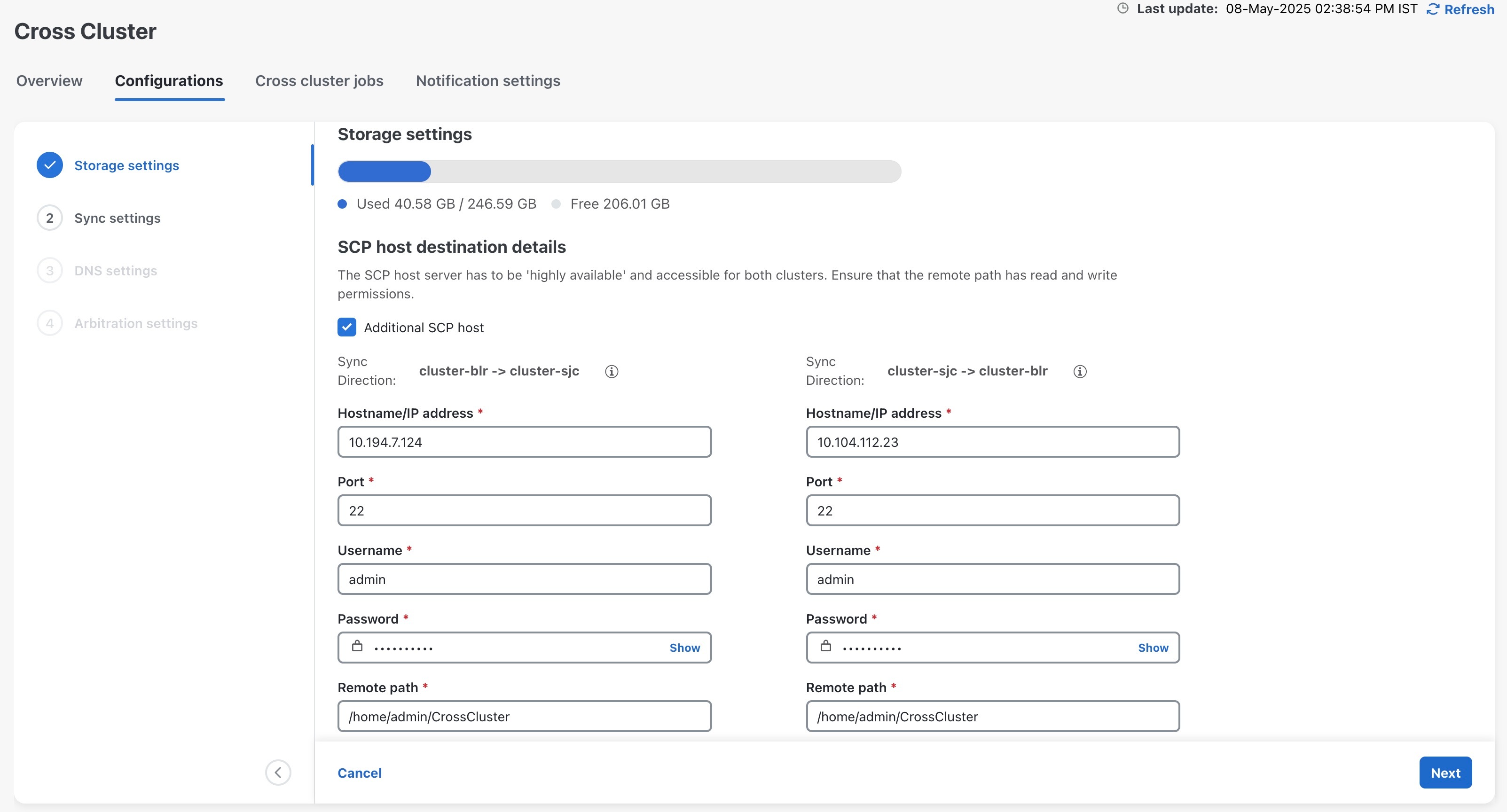
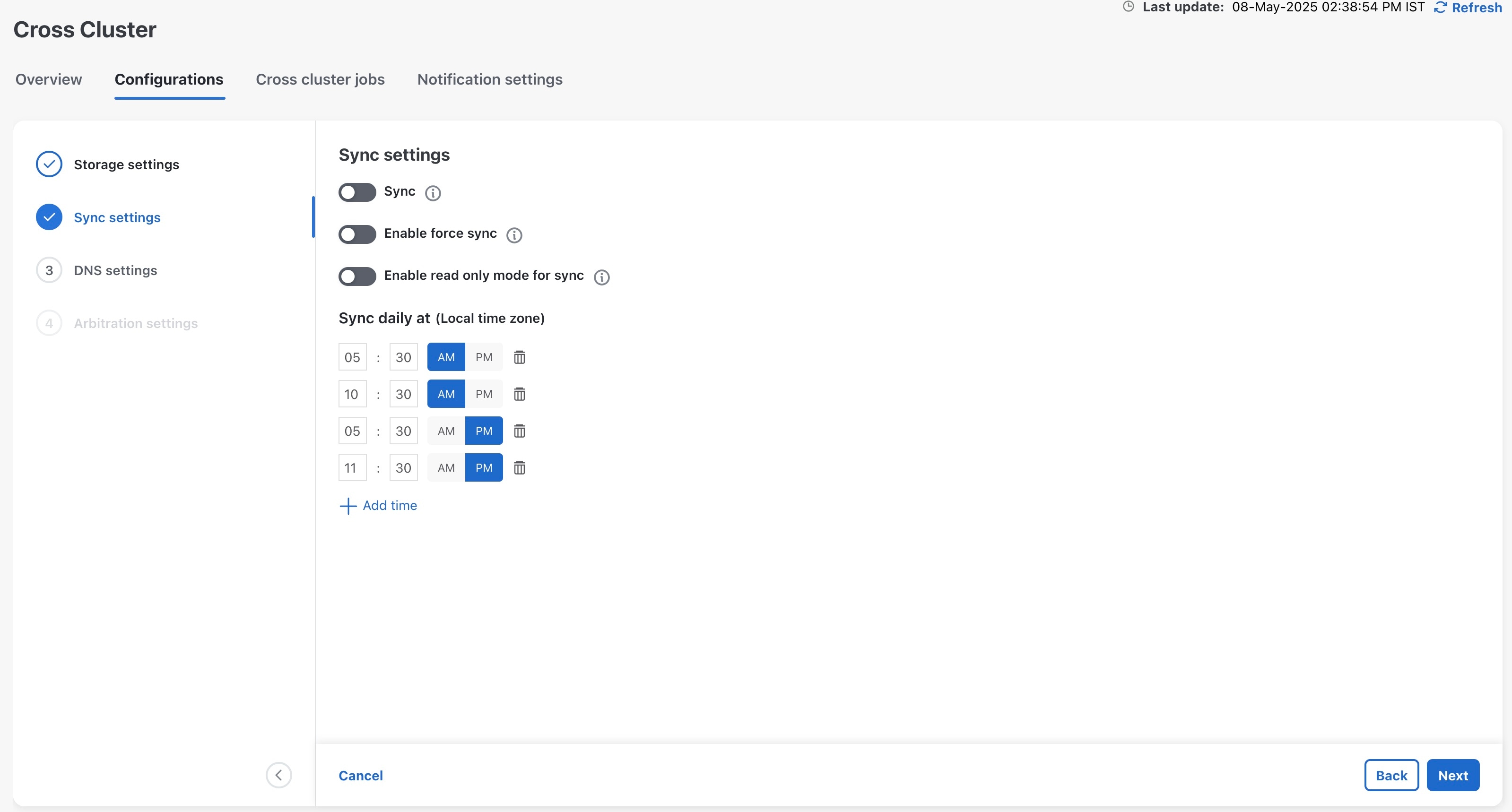
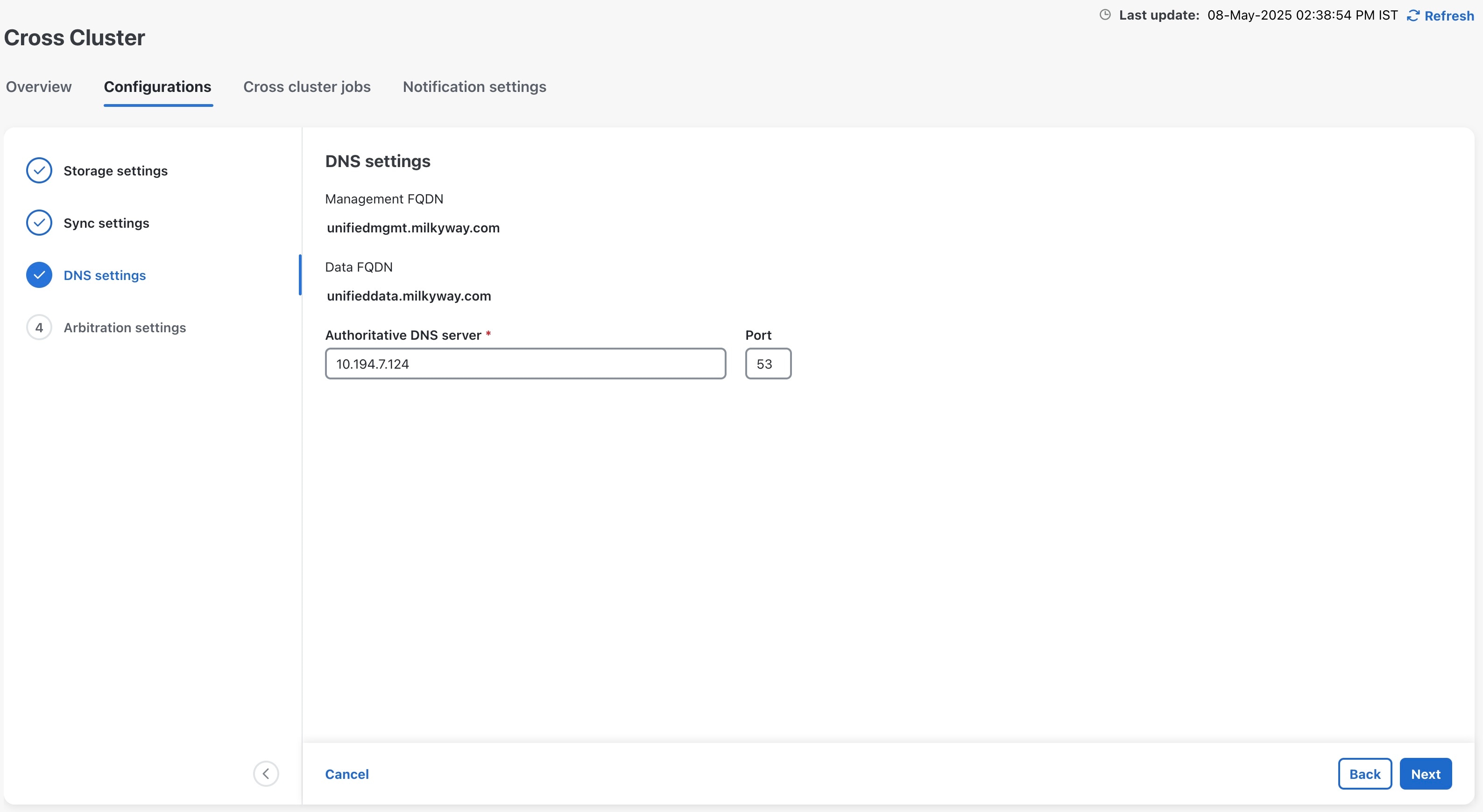
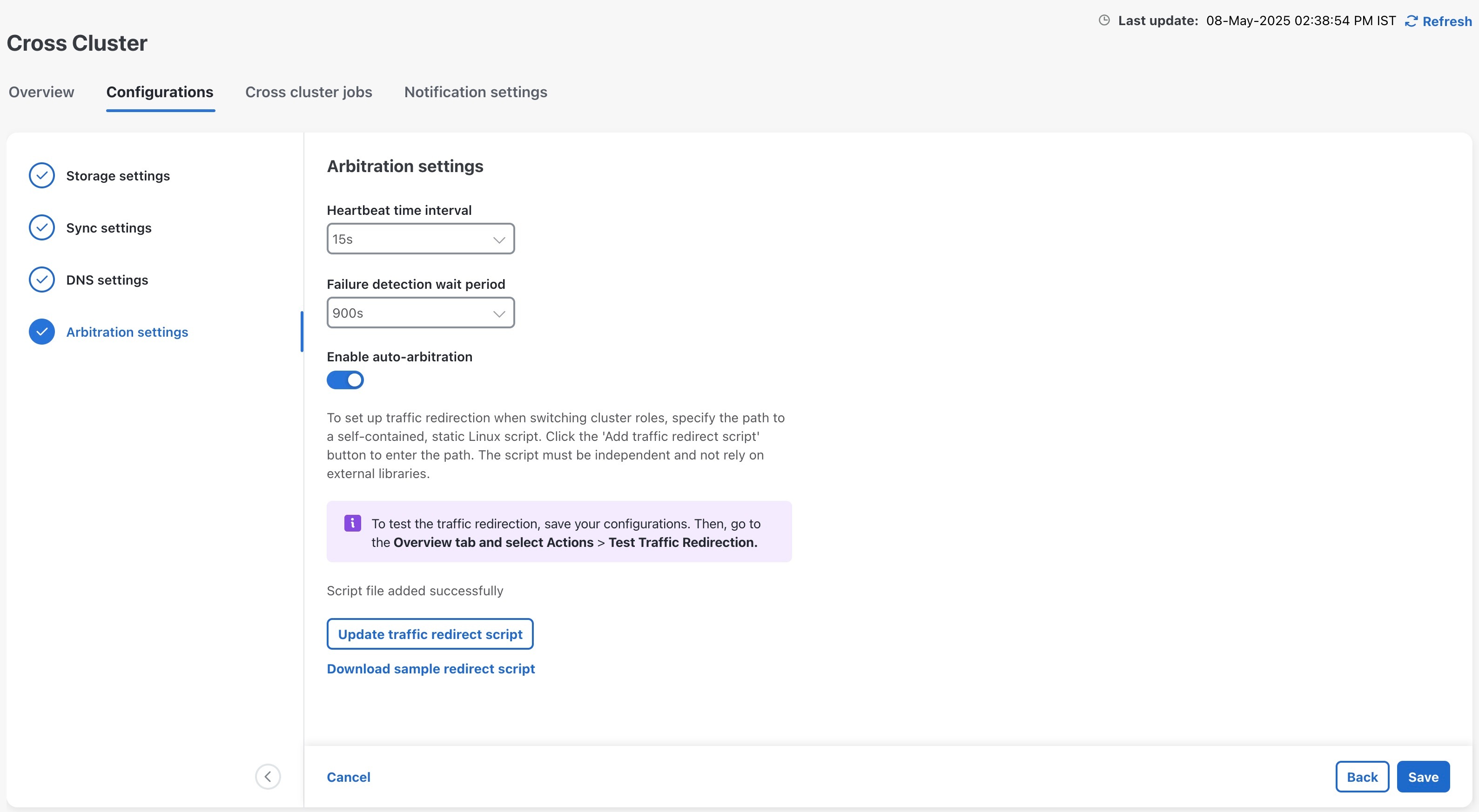
9. Configure the cross cluster settings.
|
Follow the instructions in topics below:
|
|
10. Complete an on-demand sync operation successfully.
|
On the Cross Cluster window, select to initiate the sync operation.
|
|
11. Install the Crosswork Applications on the active cluster.
|
Follow the instructions in Install Crosswork Network Controller applications topic.
Once geo redundancy is enabled, a Geo Redundancy tile is added to the Application management window. This tile is built-in and cannot be upgraded, uninstalled, or deactivated.
|
Warning
|
-
Parallel installation of applications on the active and standby clusters should be avoided. Complete the installation on the
active cluster before proceeding with the installation on the standby cluster.
-
Applications should not be installed during a periodic or on-demand sync operation. Ensure there is sufficient time for the
installation to complete before initiating a sync, and verify that no sync operation is in progress before installing an application.
It is recommended to temporarily disable periodic sync when installing applications.
|
|
|
12. Install the Crosswork Applications on the standby cluster.
|
Note
|
Applications on the standby site remain in a degraded state until the first sync completes.
|
|
|
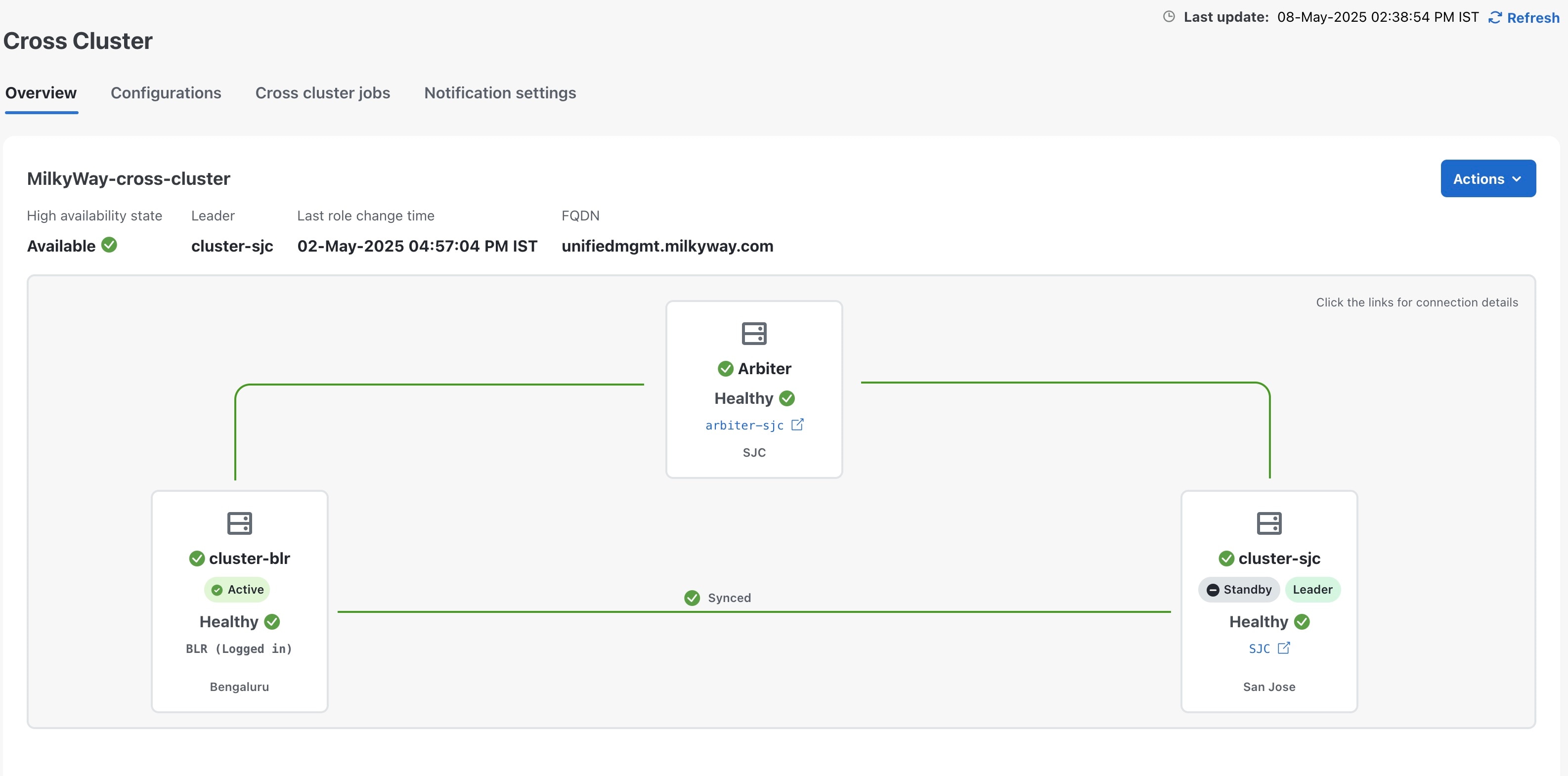
13. Verify that the geo redundancy was successfully enabled on the active and standby clusters.
|
Perform these checks:
-
In the Cross Cluster Health Status, ensure the operational state is Connected.
-
In the Cross Cluster Health Status, ensure that active cluster state is Healthy.
-
In the Cross Cluster Health Status, ensure that standby cluster state is Healthy.
-
In the Cross Cluster Health Status, ensure the High Availability state is AVAILABLE.
-
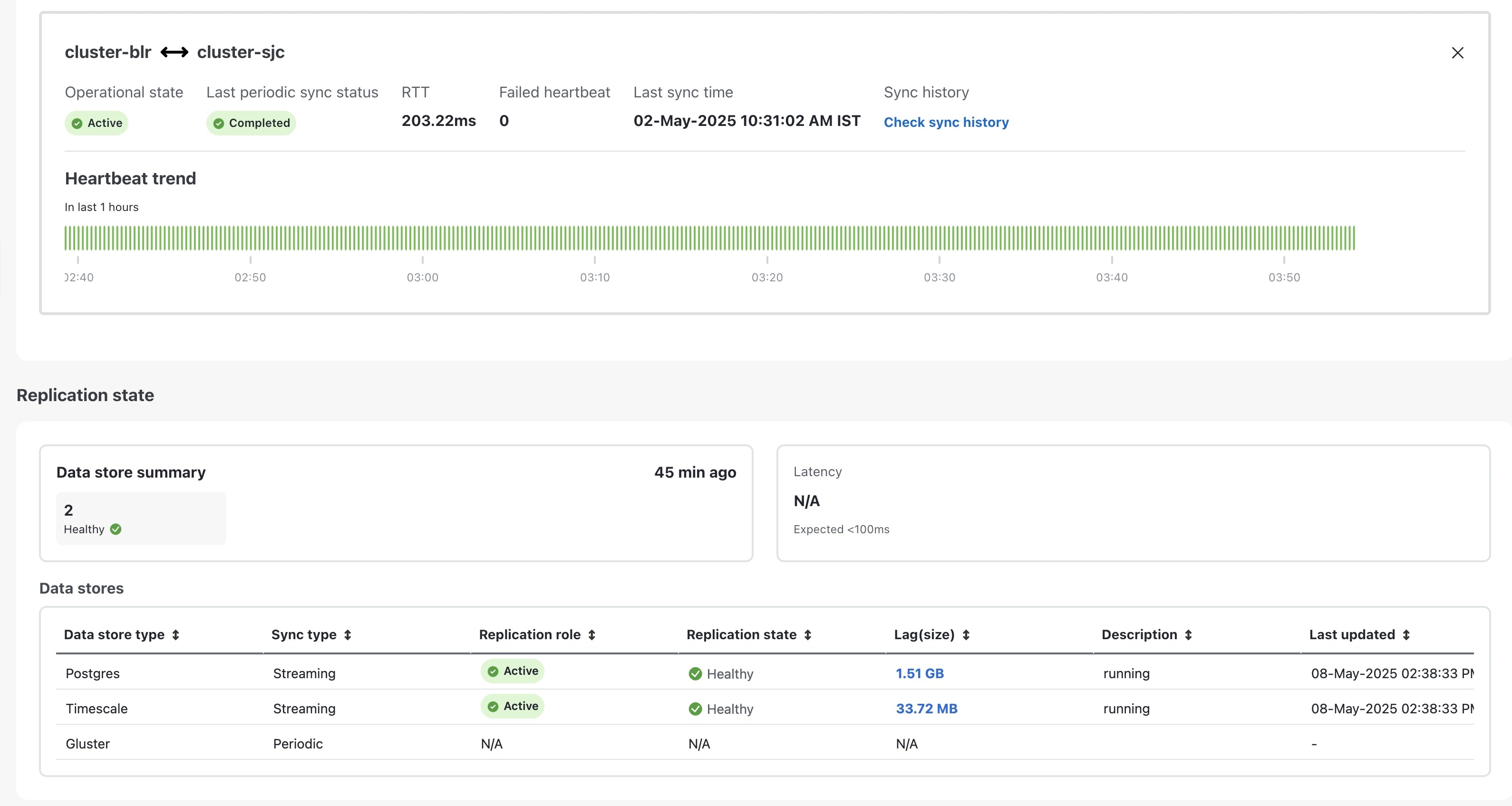
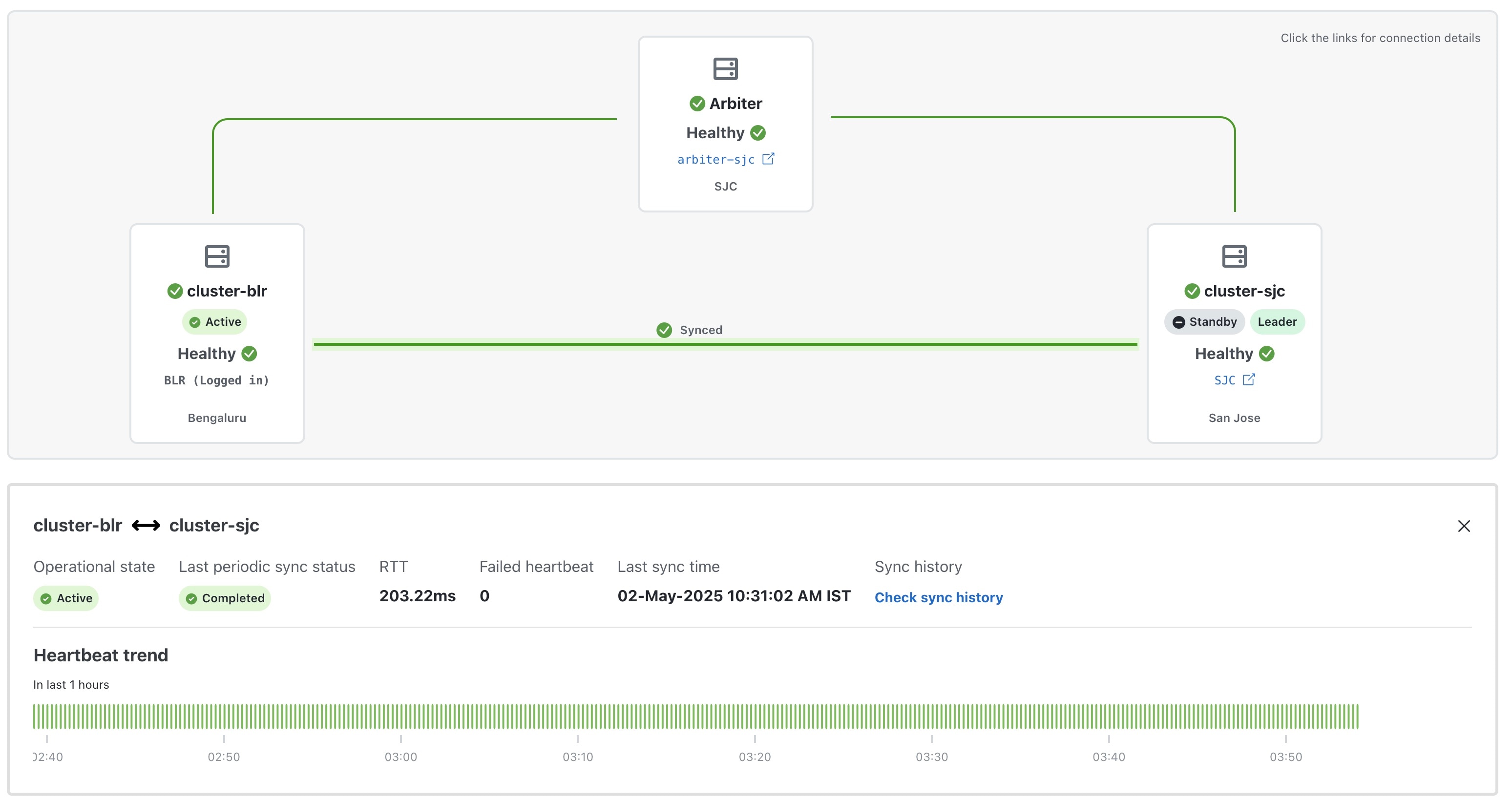
Verify that the heartbeat count between the clusters is incrementing and that no failures are observed over a 30-minute period.
-
Confirm the completion of one successful sync between the clusters.
For more information, see View Cross Cluster Status topic.
|
|
Onboard the arbiter VM
|
|
14. Update the cross cluster inventory file with details of the arbiter VM.
|
Follow the instructions in Prepare the cross cluster inventory topic.
See Sample cross cluster inventory templates for relevant example scenarios that fit your requirement.
|
|
15. Import the cross cluster inventory file again, and enable geo redundancy on the arbiter VM.
|
Perform these steps:
-
Import the active cluster inventory.
-
Import the standby cluster inventory.
-
Enable geo redundancy on the arbiter VM.
For more information, see Enable Geo Redundancy topic.
|
|
16. Configure the cross cluster settings
|
Follow the instructions in topics below:
|
|
17. Verify that the geo redundancy was successfully enabled on all the AZs.
|
Perform these checks:
-
In the Cross Cluster Health Status, ensure the operational state is Connected.
-
In the Cross Cluster Health Status, ensure that active cluster state is Healthy.
-
In the Cross Cluster Health Status, ensure that standby cluster state is Healthy.
-
In the Cross Cluster Health Status, ensure that arbiter VM state is Healthy.
-
In the Cross Cluster Health Status, ensure the High Availability state is AVAILABLE.
-
Verify that the heartbeat count between the clusters is incrementing and that no failures are observed over a 30-minute period.
-
Confirm the completion of one successful sync between the clusters.
For more information, see View Cross Cluster Status topic.
|


 Feedback