Initial Gateway Setup

You can perform the initial gateway setup using either of the following methods:

Connect to the gateway for setup

This task enables the initial setup of the gateway by connecting directly with a keyboard and monitor. It ensures that the system is powered on and accessible for configuration.

Use this procedure when setting up the gateway for the first time or when local access is required for configuration. This is typically performed during installation or troubleshooting scenarios where remote access is not available.

Before you begin

Connect a keyboard and monitor directly to the system for setup. This procedure uses a KVM cable (Cisco PID N20-BKVM) or the ports on the rear panel.

Procedure


Step 1

Attach a power cord to each power supply port, and then attach each power cord to a grounded power outlet.

Wait for approximately two minutes to let the gateway boot to standby power during the first bootup. You can verify system power status by looking at the system Power Status LED on the front panel. The system is in standby power mode when the LED is amber.

Step 2

Connect a USB keyboard and VGA monitor to the gateway using one of the following methods:

  • Connect an optional KVM cable (Cisco PID N20-BKVM) to the KVM connector on the front panel. Connect your USB keyboard and VGA monitor to the KVM cable.

  • Connect a USB keyboard and VGA monitor to the corresponding connectors on the rear panel.

Step 3

To connect with the Cisco IMC Configuration interface:

  1. Press and hold the front panel power button for four seconds to boot the gateway.

  2. During bootup, press F8 when prompted to open the Cisco IMC Configuration interface.

    Note


    The first time that you enter the Cisco IMC Configuration interface, you are prompted to change the default password. The default password is password .

    The password feature is enabled. The following are the requirements for password:

    • The password can have a minimum of 8 characters and a maximum of 14 characters.

    • The password must not contain the user’s name.

    • The password must contain characters from three of the following four categories:

      • English uppercase letters (A through Z)

      • English lowercase letters (a through z)

      • Base 10 digits (0 through 9)

      • Non-alphabetic character: !, @, #, $, %, ^, &, *, -, _, =, ,

Step 4

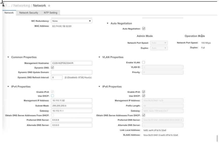
By default, the Cisco IMC uses DHCP to receive the IP address of the device. To assign a static IP address to CIMC using CLI, see the latest CLI configuration guide at Cisco UCS C-Series Servers Integrated Management Controller .


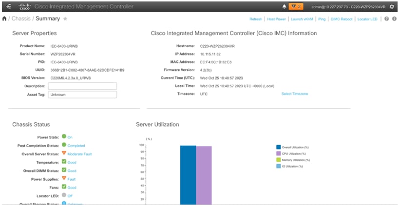
After completing these steps, the gateway is powered on, and you can access the Cisco IMC Configuration interface for further configuration. The system is ready for network setup and management.

Configure the Cisco Integrated Management Controller

Configure the Cisco Integrated Management Controller (IMC) to provide network access and enable device management. This task ensures the IMC is set up with a static IP address and ready for further configuration.

Initially, the Cisco Integrated Management Controller (IMC) management port must be configured with a static IP address. To configure Cisco IMC, follow these steps:.

This task is relevant when setting up a new device or reconfiguring the IMC for network access and management.

Before you begin

Ensure you have access to the device and the required network infrastructure, including a DHCP server if using dynamic IP assignment.

  • Power supply and grounded power outlet are available.

  • Management ethernet cable is ready for connection.

Follow these steps to configure the Cisco Integrated Management Controller:

Procedure


Step 1

Connect the power cord to each power supply port, and then connect each power cord to the grounded power outlet.

Wait for approximately two minutes during the first bootup for the gateway to enter standby power mode. The LED on the front panel turns to amber when the system is in standby power mode.

Step 2

Plug your management ethernet cable into the dedicated management interface (port 9) on the rear panel.

Step 3

Connect through the CIMC LAN management interface (port 9) to the network, which has a DHCP server, to obtain the IP address <a.b.c.d> of the device. Open the web browser and enter the following URL: https//:<A.B.C.D>/ (Or) Press and hold the power button for four seconds to boot the gateway.

Note


The first time that you enter the Cisco IMC configuration interface, you are prompted to change the default password. The default password is password.

The following are the requirements for password:

  • The password must have minimum of 8 characters and a maximum of 14 characters.

  • The password must not contain the user’s name.

  • The password must contain characters from three of the following four categories:

    • English uppercase letters (A through Z)

    • English lowercase letters (a through z)

    • Base 10 digits (0 through 9)

    • Non-alphabetic characters:

      Character

      Sign

      Exclamation mark

      !

      At sign

      @

      Hashtag

      #

      Dollar

      $

      Percentage

      %

      Circumflex

      ^

      Ampersand

      &

      Asterisk

      *

      Minus sign

      -

      Underscore

      _

      Equal

      =

      Comma

      ,

Step 4

Click at the left corner.

A left pane appears.

Step 5

Go to Admin > Networking.

A new Network page appears.

Step 6

In the IPv4 Properties, uncheck the Use DHCP check box.

Note


Before you enable DHCP, you must preconfigure your DHCP server with the range of MAC addresses for this gateway.

The NIC mode is Dedicated as there is a dedicated ethernet management port and it must not be changed.

Step 7

Enter the Management IP Address, Subnet Mask, Gateway, Preferred DNS Server, and Alternate DNS Server fields.

The static IPv4 and IPv6 settings include the following:

  • Cisco IMC IPv4 address

  • Gateway IPv4 address

    For IPv6, if you do not know the gateway, you can set it as none by entering :: (two colons).

  • Preferred DNS server address

    For IPv6, you can set this as none by entering :: (two colons).

Step 8

Perform these optional steps, if required.

  1. Update the VLAN Properties.

  2. Set a hostname for the server.

  3. Enable dynamic DNS and set a dynamic DNS (DDNS) domain.

Step 9

Click Save Changes.


The device reboots and you must refresh the browser to establish connection with the new management IP address.

Connect to the gateway console port

This task enables you to access the gateway’s CLI locally by connecting your computer to the gateway’s console port. This is useful for initial configuration or when network access is unavailable.

Use this procedure when you need to configure the gateway locally without connecting to a wired LAN. Connecting through the console port allows direct access to the CLI for setup or troubleshooting.

Procedure


Step 1

Connect a nine-pin female DB-9 to RJ-45 serial cable on one side to the RJ-45 serial port on the gateway and the other side to the COM port on a computer.

Step 2

Set up a terminal emulator to communicate with the gateway. In the terminal emulator, use the following settings:

Parameter

Value

Baud rate

115200 bps

Data

Eight bits

Parity

No

Stop

One stop bit

Flow Control

No

Step 3

If you are logging in for the first time, use the standard command prompt (>) mode to execute unprivileged commands. Use the default username and password to login: Cisco.

Note


Once the initial configuration completes, ensure that you remove the serial cable from the gateway.