Configuring Advanced Settings

Configure SNMP using CLI

URWB software for network management functionalities uses SNMP applications. The SNMP implementation supports queries (solicited) and traps (unsolicited). If you enable SNMP traps, specify the server address to which the monitoring information is sent.


Note


The same SNMP configuration must be set for all gateways in the network.


Before you begin

All parameters of SNMP are required to be configured before enabling SNMP feature using the snmp enabled command.

Procedure


Step 1

Configure the SNMP v2 parameters using these commands:

  1. Use the snmp [enabled | disabled] command to enable or disable SNMP functionality.

    Example:

    Device# snmp enabled
  2. Use the snmp version{v2c | v3} command to specify the SNMP protocol version.

    Example:

    Device# snmp version v3
  3. Use the snmp event-trap{enabled| disabled} command to enable or disable SNMP event traps.

    Example:

    Device# snmp event-trap enabled 
  4. Use the snmp periodic-trap{enabled| disabled} command to specify the SNMP v3 encryption protocol (SNMP v3).

    Example:

    Device# snmp periodic-trap enabled 
  5. Use the snmp trap-period length command to specify the notification trap period for periodic SNMP traps.

    Example:

    Device# snmp trap-period 200

    Note


    Notification value trap period measured in minutes.

  6. Use the snmp nms-hostname{hostname| ip-address} command to specify the SNMP NMS hostname or IP address.

    Example:

    Device# snmp nms-hostname 10.1.1.5
  7. Use the snmp community-idlength length command to specify the SNMP v2c community ID number (SNMP v2c).

    Example:

    Device# snmp community-id length 64

Step 2

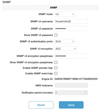
Configure the SNMP v3 parameters using these commands:

  1. Use the snmp nms-hostname{hostname| ip-address} command to specify the SNMP NMS hostname or IP address.

    Example:

    Device# snmp nms-hostname 10.1.1.5
  2. Use the snmp periodic-trap{enabled| disabled} command to specify the SNMP v3 encryption protocol (SNMP v3).

    Example:

    Device# snmp periodic-trap enabled 
  3. Use the snmp usernamelength length command to specify the SNMP v3 username (SNMP v3).

    Example:

    Device# snmp username length 32
  4. Use the snmp passwordlength length command to specify the SNMP v3 user password (SNMP v3).

    Example:

    Device# snmp password length 32
  5. Use the snmp auth-methodmethod command to specify the SNMP v3 authentication protocol (SNMP v3).

    Example:

    Device# snmp auth-method SHA-256
  6. Use the snmp encryption{aes| none} command to specify the SNMP v3 encryption protocol (SNMP v3).

    Example:

    Device# snmp encryption aes

    Note


    Possible encryption value is aes. Alternatively, enter none if the v3 encryption protocol is not needed.

  7. Use the snmp secretlength length command to specify the SNMP v3 encryption passphrase (SNMP v3).

    Example:

    Device# snmp secret length 32
  8. Use the snmp periodic-trap{enabled| disabled} command to specify the SNMP v3 encryption protocol (SNMP v3).

    Example:

    Device# snmp periodic-trap enabled 
  9. Use the snmp event-trap{enabled| disabled} command to enable or disable SNMP event traps.

    Example:

    Device# snmp event-trap enabled 

Configure SNMP version v2c using GUI

This task enables SNMP version v2c on gateways and configures community identity, event traps, and periodic traps for network monitoring.

By default, the gateways are shipped from the factory with SNMP in disabled mode.

Follow these steps to change the gateway's SNMP mode to version v2c and configure the gateway:

Procedure


Step 1

Choose the version v2c from the SNMP mode drop-down list.

The SNMP window appears.

The configuration interface for enabling SNMP version v2c on gateways, showing options for community identity, event traps, and periodic traps.

Step 2

Enter the community identity value in the Community ID field.

Important


The same community identity value must be set for all the gateways in the network.

Step 3

Check the Enable SNMP event trap check box to enable SNMP event traps for significant system-related events, and then enter the network management station (NMS) host name in the NMS hostname field.

Important


The NMS host to which traps are sent must have an SNMP agent that is configured to collect SNMP v2c traps.

Step 4

Check the Enable SNMP periodic trap check box to enable periodic SNMP traps to send SNMP traps at defined periodic intervals and then enter the host name of NMS in the NMS hostname field. Enter the notification period (minutes) in the Notification period.

Step 5

Click Save.


Configure SNMP version v3 using GUI

Configure SNMP version v3 on gateways to enable secure network monitoring and management with authentication and encryption capabilities.

By default, SNMP is disabled on gateways when shipped from the factory. SNMP v3 enhances network management security by providing authentication and encryption features.

Before you begin

Follow these steps to change the gateway's SNMP mode to version v3 and configure the gateway:

Procedure


Step 1

Choose the version v3 from the SNMP mode drop-down list.

The SNMP window appears.

The configuration steps for enabling SNMP version v3 on the gateway, highlighting the necessary settings for authentication and encryption.

Step 2

Enter the SNMP v3 username in the SNMP v3 username field.

Note


The same SNMP v3 username must be set for all the gateways in the network.

Step 3

To change the current SNMP v3 password, enter the new password in the SNMP v3 password field.

Check the Show SNMP v3 password check box to see the SNMP v3 password field.

Step 4

Choose the authentication type from the SNMP v3 authentication proto drop-down list. The available options are:

  • MD5

  • SHA

  • SHA-224

  • SHA-256

  • SHA-384

  • SHA-512

Important


The same SNMP authentication protocol must be set for all the gateways in the network.

Step 5

Choose the appropriate encryption protocol from the SNMP v3 encryption drop-down list. The available options are:

  • No Encryption

  • AES (Advanced Encryption Standard)

Note


The same encryption protocol must be set for all the gateways in the network.

Step 6

To change the encryption passphrase, enter a new passphrase in the SNMP v3 encryption passphrase field.

Step 7

Check the Enable SNMP event trap check box to enable the SNMP event traps for significant system-related events and then enter the host name of NMS in the NMS hostname field.

Note


The NMS host to which traps are sent must have an SNMP agent configured to collect v3 traps.

Step 8

Check the Enable SNMP periodic trap check box to enable the periodic SNMP traps to send SNMP traps at defined periodic intervals and then enter the host name of NMS in the NMS hostname field. Enter the notification period (minutes) in the Notification period.

Step 9

Click Save.


Configure NTP using GUI

Configure NTP to synchronize the gateway's time settings with a network time server.

The gateway has NTP functionality that allows it to synchronize the time settings with a chosen network time server.


Important


The same NTP configuration must be set for all the gateways in the network. If the same NTP settings are not applied to all gateways, the network may encounter timestamp conflicts and/or device malfunctions.


Procedure


Step 1

In the ADVANCED SETTINGS, click ntp.

The NTP - Network Time Protocol window appears.

The NTP configuration interface displays the settings that must be applied to all gateways in the network to prevent timestamp conflicts and device malfunctions.

Step 2

Check the Enable NTP check box to enable the NTP synchronization.

Step 3

Enter the host name of a chosen primary NTP server in the NTP server hostname field.

Step 4

Choose the authentication method from the NTP authentication drop-down list.

Available options:

  • None (does not require an NTP password)

  • SHA1

  • SHA256

  • SHA512

Step 5

Enter the password in the NTP password field.

Check the show check box to see the NTP password field.

Note


To configure a new password using a GUI or CLI, the password should match the criteria:

  • The password must be at least 10 characters.

    See the CLI section for information on the special characters that are not allowed.

Step 6

Enter the NTP key id in the NTP key id field.

Step 7

Choose the time zone from the Select Timezone drop-down list.

Step 8

Click Save.


Configure NTP using CLI

Configure Network Time Protocol (NTP) settings to synchronize system time with reliable time servers and ensure accurate timestamps across network devices.

NTP configuration allows you to set up time synchronization for your device by specifying server addresses, authentication methods, timezone settings, and service status. Proper time synchronization is essential for network operations, logging, and security functions.

Procedure


Step 1

Configure the NTP server address using the ntp server string command.

String - IP address or domain name.

Example:

Device# ntp server 192.168.216.201

Step 2

Configure NTP authentication using the ntp server-auth {None| SHA1| SHA256| SHA512} password key-id command.

none - disable NTP authentication md5

sha1 - authentication method

Example:

Device# # ntp server-auth SHA1 test12345 65535

Note


To configure a new password using a GUI or CLI, the password should match the following criteria:

  • The password must be at least 10 characters.

  • The following special characters are not allowed:

    Table 1. Special characters

    Character

    Description

    '

    apex

    "

    double apex

    `

    backtick

    $

    dollar

    =

    equal

    \

    backslash

    #

    number sign

    &

    ampersand

    < >

    angle brackets

    %

    percent sign

    white spaces

Step 3

Enable or disable the NTP service, use the ntp {enabled | disabled} .

Example:

Device# ntp enabled

Step 4

Configure the NTP timezone use the ntp timezone string .

Example:

Device# ntp timezone Asia/Shanghai

Step 5

(Optional) Use the ntp command to validate NTP configuration and status.

Example:

Device# ntp
NTP: enabled
NTP: 192.168.216.201
Server auth: SHA1
Timezone: Asia/Shanghai
Current date: Thu 02 Nov 2023 07:15:02 PM CET

Configure L2TP using GUI

Layer 2 Tunneling Protocol (L2TP) functionality allows the devices to support integration of URWB Fluidity technology in Layer 3 networks.

Follow these steps to configure L2TP links:

Procedure


Step 1

In the ADVANCED SETTINGS, click lt2p configuration.

The L2TP Configuration window appears.

The L2TP Configuration window displays the detailed settings required for configuring Layer 2 Tunneling Protocol links.

Step 2

Check the L2TP check box to enable the configuration.

The L2TP detailed configuration SETTINGS appears.

The L2TP Configuration window displays fields for entering the WAN IP Address, WAN Netmask, and WAN Gateway settings for configuring L2TP links.

Step 3

Enter the following details:

  • WAN IP Address

  • WAN Netmask

  • WAN Gateway

  • Local UDP Port

  • Max number of L2TP tunnels

Step 4

Click Save.

Step 5

To add a L2TP tunnel to remote host:

  1. Enter the Remote WAN IP Address and Remote UDP Port details.

  2. Click Add.


Configure L2TP using CLI

Configure L2TP (Layer 2 Tunneling Protocol) settings to establish secure tunnel connections between network devices using command-line interface commands.

Use these CLI commands to manage L2TP configuration on your device, including enabling the service, setting interface parameters, configuring WAN settings, and managing tunnel connections.

Procedure


Step 1

Use the l2tp status {enable | disable} command to enable or disable the L2TP configuration.

Example:

l2tp status enable

Step 2

Use the l2tp interface {1 | 2} command to set the interface port for L2TP communication with the gateway.

Port 1 = ethernet LAN ports bridge

Port 2 = SFP+ ports bridge

Example:

Device# l2tp interface 1

Step 3

Use the l2tp wan WAN-IP-address WAN-net-mask WAN-gateway-address command to configure L2TP WAN parameters.

Device# l2tp wan 192.168.0.20 255.255.255.0 192.168.0.1

Step 4

Use the l2tp port UDP port command to configure L2TP WAN interface port.

Example:

Device# l2tp port 5701

Note


The unsigned integer range of UDP port of remote peer is [1-65535].

Step 5

Use the l2tp port remote-peer-ip remote-peer-udp-port-num command to add a L2TP tunnel to remote host.

Example:

Device# l2tp add 192.168.20.20 5701

Note


The unsigned integer range of UDP port of remote peer is [1-65535].

Step 6

Use the l2tp command to print the current list of L2TP tunnels.

Example:

Device# l2tp

Step 7

Use the l2tp del tunnel-ID command to delete the L2TP tunnel.

Example:

Device# l2tp del 12

tunnel-ID – It is shown in the list of L2TP tunnels. Use command l2tp to print the list.


Configure VLAN SETTINGS

Configure VLAN SETTINGS to connect the gateway to a VLAN that is part of the local wireless network.

Default VLAN configuration factory-set parameters for the gateway are:

Parameter

Default value

Management VLAN ID (MVID)

1

Native VLAN ID (NVID)

1

Procedure


Step 1

In the ADVANCED SETTINGS, click VLAN SETTINGS.

The VLAN SETTINGS window appears.

The VLAN SETTINGS window displays the configuration options for setting the Native VLAN ID (NVID) to 1, along with additional settings for packet management.

Step 2

Check the Enable VLANs check box to connect the gateway to a VLAN that is part of the local wireless network.

Step 3

Enter the management identification number of the VLAN in the Management VLAN ID field.

For detailed info about VLAN SETTINGS and packet management, see Rules for Packet Management.

Note


The same Management VLAN ID must be used on all the gateways that are part of the same mesh network.

Step 4

Enter the native identification number of the VLAN in the Native VLAN ID field.

Step 5

Click Save.


Rules for packet management

This reference provides the rules and default parameter values that govern how packets are managed, processed, and classified in the system. It includes traffic classification parameters, access port rules for both incoming and outgoing packets, and special handling rules for gateways operating in smart mode.

Parameter

Default value

Native VLAN processing

Enabled

Port mode (all Ethernet ports)

Smart

Traffic management

The incoming data packets are classified based ON these parameter values:

Parameter

Default value

Signaling

Ethernet protocol type

User

All other traffic

Packet tagged with MVID

Packet allowed

Access port rules for incoming packets

Untagged packet from the gateway

Packet allowed

Untagged packet with VLAN ID (VID) is not configured

Packet allowed

Untagged packet with VID is configured

Packet tagged with specified VID

Tagged packet with valid VID

Packet dropped

Tagged packet with null (0) VID

Packet dropped

Access port rules for outgoing packets

Tagged packet with configured and allowed VID

Packet allowed

Packet from the gateway

Packet allowed

Tagged packet with VID is not configured

Packet allowed

Parameter

Default value

Tagged packet with valid VID, but not allowed

Packet dropped

Tagged packet with null (0) VID

Packet dropped

Access port rules management for incoming packets with a gateway in smart mode

Untagged packet

If native VLAN is ON, then the packet is allowed (tagged with NVID)

If native VLAN is OFF, then the packet is dropped

Tagged packet (any VID without any check)

Packet allowed with original tag

Access port rules management for outgoing packets with a gateway in smart mode

Packets from the gateways (for example: IoT OD IW interface)

Packet tagged with MVID

Signaling traffic

Packet tagged with MVID

Tagged with valid VID (1–4095), but not with NVID

Packet allowed (tagged)

Tagged with null VID (0) or NVID

Packet allowed (untagged)


Note


The packets transmitted through the Cisco VIC SFP+ interface is always tagged with a VLAN header. The outgoing packets from the interface are classified as untagged with an IEEE 802.1p header and VLAN ID tag of 0.


Configure FLUIDITY settings using GUI

Configure FLUIDITY functionality on gateways to enable mesh networking capabilities and define network architecture settings.

By default, the gateways are shipped from the factory with FLUIDITY functionality in disabled mode. You can enable and configure FLUIDITY settings through the GUI interface.

Before you begin

Follow these steps to change the FLUIDITY settings:

Procedure


Step 1

In the ADVANCED SETTINGS, clickFLUIDITY.

The FLUIDITY window appears.

The GUI interface displays the FLUIDITY settings configuration options, including the Unit Role drop-down menu set to Infrastructure mode, which is unchangeable.

Step 2

Check the FLUIDITY check box to enable the FLUIDITY functionality.

Note


The Unit Role drop-down is set to Infrastructure mode, and it cannot be changed.

Step 3

Select the network type designation for the gateway from the Network Type drop-down list. Set this option in accordance with the general network architecture. Following are the available options from the network type:

  • Flat: Choose this option, if both the mesh network and the infrastructure network belong to a single layer 2 broadcast domain.

  • Multiple Subnets: Choose this option, if the mesh network and the infrastructure network are organized as separate layer 3 routing domains.

Step 4

Click Save.


Configure Fluidity Settings using CLI

To enable fluidity, at least one radio interface should be in fluidity mode.

Procedure


Use the fluidity status enabled command to enable the fluidity status.

Example:

Device# fluidity status enabled

Configure gateway STATUS

The gateway STATUS window shows information on basic settings (including the gateway's MAC address) and allows you to download DIAGNOSTIC data files and view event LOGS.

Access gateway STATUS

In the MANAGEMENT SETTINGS, click STATUS.

  • The STATUS window appears.

The gateway STATUS window displays the gateway's MAC address, diagnostic data download options, and event logs, providing an overview of the device's basic settings and status.

STATUS section details

These details are shown in the STATUS section:

  • Device details

  • Device settings

  • Ethernet ports

Additional STATUS section areas

These sections are available in other parts of the STATUS section:

  • DIAGNOSTIC TOOL: To download diagnostics of the Device.

  • Open services: To show or hide services.

  • DEVICE LOGS: To show or clear LOGS.