- Preface
- Overview
- Installing the Server Operating System or Hypervisor
- Managing the Server
- Managing Storage Using RAID
- Viewing Server Properties
- Viewing Server Sensors
- Managing Remote Presence
- Managing User Accounts
- Configuring Network-Related Settings
- Configuring Communication Services
- Managing Certificates
- Configuring Platform Event Filters
- Firmware Management
- Viewing Faults and Logs
- Server Utilities
- Diagnostic Tests
- Index
Managing the Server
This chapter includes the following sections:
- Viewing Overall Server Status
- Configuring the Server Boot Order Using the CIMC GUI
- Configuring the Boot Order Using the BIOS Setup Menu
- Resetting the Server
- Shutting Down the Server
- Locking or Unlocking Cisco IOS CLI Configuration Changes
- Managing Server Power
- Configuring BIOS Settings
Viewing Overall Server Status
Configuring the Server Boot Order Using the CIMC GUI
Log into CIMC as a user with admin privileges.
| Step 1 | In the Navigation pane, click the Server tab. | ||||||||||||||
| Step 2 | On the
Server tab, click
BIOS.
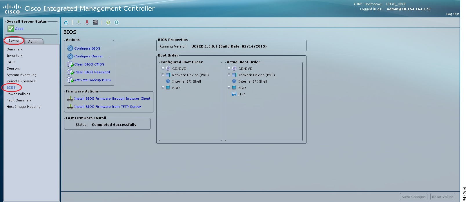 | ||||||||||||||
| Step 3 | In the
Actions area, click
Configure Boot Order.
The Configure Boot Order dialog box appears. 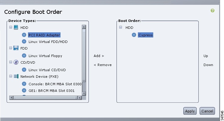 | ||||||||||||||
| Step 4 | In the
Configure
Boot Order dialog box, complete the following fields as appropriate:
| ||||||||||||||
| Step 5 | Click
Apply.
Additional device types may be appended to the actual boot order, depending on what devices you have connected to your server. |
What to Do Next
Reboot the server to boot with your new boot order.
Configuring the Boot Order Using the BIOS Setup Menu
Use this procedure if you want the server to boot from an external bootable device, such as a USB or an external CD-ROM drive that is directly connected to the E-Series Server or NCE.
| Step 1 | In the Navigation pane, click the Server tab. |
| Step 2 | On the Server tab, click Summary. |
| Step 3 | From the
Actions area, click
Launch
KVM Console.
The KVM Console opens in a separate window. |
| Step 4 | From the Server Summary page, click Power Cycle Server to reboot the server. |
| Step 5 | When
prompted, press
F2 during bootup to access the BIOS setup menu.
The Aptio Setup Utility appears, which provides the BIOS setup menu options. 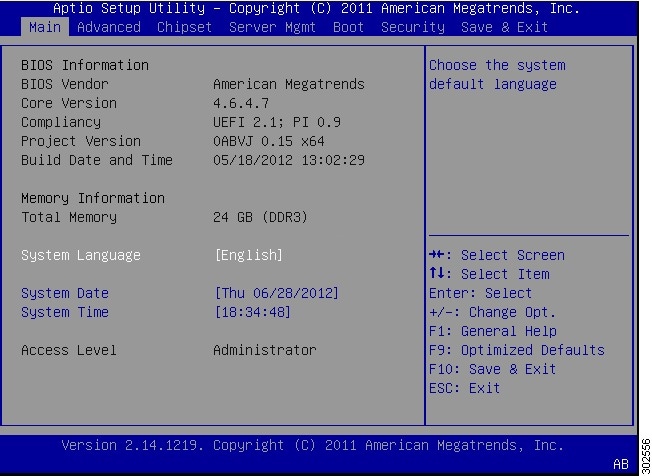 |
| Step 6 | Click the Boot tab. |
| Step 7 | Scroll down to
the bottom of the page below the
Boot
Options Priority area. The following boot option priorities are
listed:
|
| Step 8 | Use the Up or Down arrow keys on your keyboard to highlight the appropriate option. |
| Step 9 | Press Enter to select the highlighted field. |
| Step 10 | Choose the appropriate device as Boot Option 1. |
| Step 11 | Press
F4 to save changes and exit.
The Main tab of the BIOS setup displays the device that you configured as Boot Option 1. |
Resetting the Server
You must log in with user or admin privileges to perform this task.
Shutting Down the Server
You must log in with user or admin privileges to perform this task.
| Step 1 | In the Navigation pane, click the Server tab. | ||
| Step 2 | On the Server tab, click Summary. | ||
| Step 3 | In the
Actions area, click
Shut
Down Server.
A dialog box with the message Shut Down the Server? appears.
| ||
| Step 4 | Click
OK.
|
Locking or Unlocking Cisco IOS CLI Configuration Changes
Use this procedure to allow or prevent configuration changes to be made using the Cisco IOS CLI.
| Step 1 | In the Navigation pane, click the Server tab. |
| Step 2 | On the Server tab, click Summary. |
| Step 3 | To allow configuration changes to be made using the Cisco IOS CLI, from the Actions area, click Unlock IOS Configuration Changes. The button in the GUI changes to Lock IOS Configuration Changes. |
| Step 4 | To prevent configuration changes to be made using the Cisco IOS CLI, from the Actions area, click Lock IOS Configuration Changes. If you do use the Cisco IOS CLI to make configuration changes, a warning message displays and the configuration is ignored. The button in the GUI changes to Unlock IOS Configuration Changes. |
| Step 5 | In the confirmation window, click OK. |
Managing Server Power
Powering On the Server
 Note | If the server was powered off by any means other than through CIMC, it will not become active immediately when powered on. The server will remain in standby mode until CIMC completes initialization. |
You must log in with user or admin privileges to perform this task.
Powering Off the Server
Note | This procedure is not applicable to the NIM E-Series NCE. |
You must log in with user or admin privileges to perform this task.
| Step 1 | In the Navigation pane, click the Server tab. | ||
| Step 2 | On the Server tab, click Summary. | ||
| Step 3 | In the
Actions area, click
Power
Off Server.
A dialog box with the message Power Off the Server? appears. | ||
| Step 4 | Click
OK.
|
Power Cycling the Server
Note | This procedure is not applicable to the NIM E-Series NCE. |
You must log in with user or admin privileges to perform this task.
| Step 1 | In the Navigation pane, click the Server tab. | ||||
| Step 2 | On the Server tab, click Summary. | ||||
| Step 3 | In the
Actions area, click
Power
Cycle Server.
A dialog box with the message Power Cycle the Server? appears. | ||||
| Step 4 | Click
OK.
|
Locking or Unlocking the Server's Front Panel Power Button
Note | This procedure is applicable to E-Series Servers and the SM E-Series NCE. This procedure is not applicable to the EHWIC E-Series NCE and the NIM E-Series NCE. |
Use this procedure to enable or disable the physical power button, which is located on the front panel of the physical server.
| Step 1 | In the Navigation pane, click the Server tab. |
| Step 2 | On the Server tab, click Summary. |
| Step 3 | To disable the
power button, from the
Actions area, click
Lock
Front Panel Power Button.
The power button is disabled. You cannot use the front panel power button to turn the server power on or off. The button in the GUI changes to Unlock Front Panel Power Button. |
| Step 4 | To enable the
power button, from the
Actions area, click
Unlock
Front Panel Power Button.
The power button is enabled. You can use the front panel power button to turn the server power on or off. The button in the GUI changes to Lock Front Panel Power Button. |
| Step 5 | In the confirmation window, click OK. |
Locking or Unlocking the Server's Front Panel Reset Button
Note | This procedure is applicable to E-Series Servers and the SM E-Series NCE. This procedure is not applicable to the EHWIC E-Series NCE and the NIM E-Series NCE. |
Use this procedure to enable or disable the reset button, which is located on the front panel of the physical server.
| Step 1 | In the Navigation pane, click the Server tab. |
| Step 2 | On the Server tab, click Summary. |
| Step 3 | To disable the
reset button, from the
Actions area, click
Lock
Front Panel Reset Button.
The reset button is disabled. You cannot use the front panel reset button to reset the server. The button in the GUI changes to Unlock Front Panel Reset Button. |
| Step 4 | To enable the
reset button, from the
Actions area, click
Unlock
Front Panel Reset Button.
The reset button is enabled. You can use the front panel reset button to reset the server. The button in the GUI changes to Lock Front Panel Reset Button. |
| Step 5 | In the confirmation window, click OK. |
Configuring BIOS Settings
Activating the Backup BIOS
On rare occasions, the BIOS image might get corrupted. To recover from a corrupt BIOS image, activate the backup BIOS to boot the system.
Note | The backup BIOS image is factory installed. It cannot be upgraded. |
Configuring Advanced BIOS Settings
Note | Depending on your installed hardware, some configuration options described in this topic may not appear. |
You must log in with admin privileges to perform this task.
| Step 1 | In the Navigation pane, click the Server tab. | ||
| Step 2 | On the
Server tab, click
BIOS.
| ||
| Step 3 | In the
Actions area, click
Configure BIOS.
The Configure BIOS Parameters dialog box appears. | ||
| Step 4 | In the
Configure
BIOS Parameters dialog box, click the
Advanced tab.
 | ||
| Step 5 | Check or clear
the
Reboot
Host Immediately checkbox.
If checked, the server is rebooted immediately after you make changes to the BIOS parameters. To specify that the server should not reboot automatically, clear this check box. Any parameter changes will take effect the next time the server is rebooted.
| ||
| Step 6 | In the
Advanced tab, update the BIOS settings fields.
For descriptions and information about the options for each BIOS setting, see the following topics: | ||
| Step 7 | Click Save Changes. |
Configuring Server Management BIOS Settings
You must log in with admin privileges to perform this task.
| Step 1 | In the Navigation pane, click the Server tab. | ||
| Step 2 | On the
Server tab, click
BIOS.
| ||
| Step 3 | In the
Actions area, click
Configure BIOS.
The Configure BIOS Parameters dialog box appears. | ||
| Step 4 | In the
Configure
BIOS Parameters dialog box, click the
Server
Management tab.
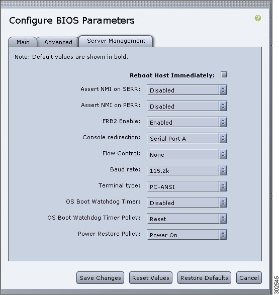 | ||
| Step 5 | Check or clear
the
Reboot
Host Immediately checkbox.
If checked, the server is rebooted immediately after you make changes to the BIOS parameters. To specify that the server should not reboot automatically, clear this check box. Any parameter changes will take effect the next time the server is rebooted.
| ||
| Step 6 | In the
Server
Management tab, update the BIOS settings fields.
For descriptions and information about the options for each BIOS setting, see the following topic: | ||
| Step 7 | Click Save Changes. |
Clearing the BIOS CMOS
Note | On rare occasions, troubleshooting a server may require you to clear the server's BIOS CMOS memory. This procedure is not part of the normal maintenance of a server. |
Clearing the BIOS Password
What to Do Next
Reboot the server for the clear password operation to take effect. You are prompted to create a new password when the server reboots.
Server BIOS Settings
The tables in the following sections list the server BIOS settings that you can view and configure.
Note | We recommend that you verify the support for BIOS settings in your server. Depending on your installed hardware, some settings may not be supported. |
Main BIOS Settings
| Name | Description |
|---|---|
|
Reboot Host Immediately Not displayed for the NIM E-Series NCE. |
If checked, the server is rebooted immediately after you click Save Changes. To specify that the server should not reboot automatically, clear this check box. Any parameter changes will take effect the next time the server is rebooted. |
Advanced: Processor BIOS Settings
| Name | Description | ||
|---|---|---|---|
|
Enhanced Intel Speedstep Technology |
Whether the processor uses Enhanced Intel SpeedStep Technology, which allows the system to dynamically adjust processor voltage and core frequency. This technology can result in decreased average power consumption and decreased average heat production. This can be one of the following:
We recommend that you contact your operating system vendor to make sure the operating system supports this feature. |
||
|
Intel Hyper-Threading Technology |
Whether the processor uses Intel Hyper-Threading Technology, which allows multithreaded software applications to execute threads in parallel within each processor. This can be one of the following:
We recommend that you contact your operating system vendor to make sure the operating system supports this feature. |
||
|
Number of Enabled Cores |
Sets the state of logical processor cores in a package. If you disable this setting, Hyper Threading is also disabled. This can be one of the following:
We recommend that you contact your operating system vendor to make sure the operating system supports this feature. |
||
|
Execute Disable |
Classifies memory areas on the server to specify where application code can execute. As a result of this classification, the processor disables code execution if a malicious worm attempts to insert code in the buffer. This setting helps to prevent damage, worm propagation, and certain classes of malicious buffer overflow attacks. This can be one of the following:
We recommend that you contact your operating system vendor to make sure the operating system supports this feature. |
||
|
Intel Virtualization Technology |
Whether the processor uses Intel Virtualization Technology (VT), which allows a platform to run multiple operating systems and applications in independent partitions. This can be one of the following:
|
||
|
Intel VT for Directed IO |
Whether the processor uses Intel Virtualization Technology for Directed I/O (VT-d). This can be one of the following: |
||
|
Intel VT-d Interrupt Remapping |
Whether the processor supports Intel VT-d Interrupt Remapping. This can be one of the following: |
||
|
Intel VT-d Coherency Support |
Whether the processor supports Intel VT-d Coherency. This can be one of the following: |
||
|
Intel VT-d Address Translation Services |
Whether the processor supports Intel VT-d Address Translation Services (ATS). This can be one of the following: |
||
|
Intel VT-d PassThrough DMA |
Whether the processor supports Intel VT-d Pass-through DMA. This can be one of the following: |
||
|
Direct Cache Access |
Allows processors to increase I/O performance by placing data from I/O devices directly into the processor cache. This setting helps to reduce cache misses. This can be one of the following: |
||
|
Processor C3 Report |
Whether the processor sends the C3 report to the operating system. This can be one of the following: |
||
|
Processor C6 Report |
Whether the processor sends the C6 report to the operating system. This can be one of the following: |
||
|
Hardware Prefetcher |
Whether the processor allows the Intel hardware prefetcher to fetch streams of data and instruction from memory into the unified second-level cache when necessary. This can be one of the following:
|
||
|
Adjacent Cache-Line Prefetch |
Whether the processor uses the Intel Adjacent Cache-Line Prefetch mechanism to fetch data when necessary. This can be one of the following:
|
||
|
Package C State Limit |
The amount of power available to the server components when they are idle. This can be one of the following:
|
||
|
Patrol Scrub |
Whether the system actively searches for, and corrects, single bit memory errors even in unused portions of the memory on the server. This can be one of the following:
|
||
|
Demand Scrub |
Whether the system allows a memory scrub to be performed on demand. This can be one of the following:
|
||
|
Device Tagging |
Whether the system allows devices and interfaces to be grouped based on a variety of information, including descriptions, addresses, and names. This can be one of the following: |
Advanced: Memory BIOS Settings
| Name | Description |
|---|---|
|
Select Memory RAS |
How the memory reliability, availability, and serviceability (RAS) is configured for the server. This can be one of the following: |
Advanced: Serial Port BIOS Settings
| Name | Description |
|---|---|
|
Serial A Enable |
Whether serial port A is enabled or disabled. This can be one of the following: |
Advanced: USB BIOS Settings
| Name | Description |
|---|---|
|
USB Port 0 |
Whether the processor uses USB port 0. This can be one of the following: |
|
USB Port 1 |
Whether the processor uses USB port 1. This can be one of the following: |
Server Management BIOS Settings
| Name | Description | ||
|---|---|---|---|
|
Reboot Host Immediately Not displayed for the NIM E-Series NCE. |
If checked, the server is rebooted immediately after you click Save Changes. To specify that the server should not reboot automatically, clear this check box. Any parameter changes will take effect the next time the server is rebooted. |
||
|
Assert NMI on SERR |
Whether the BIOS generates a non-maskable interrupt (NMI) and logs an error when a system error (SERR) occurs. This can be one of the following: |
||
|
Assert NMI on PERR |
Whether the BIOS generates a non-maskable interrupt (NMI) and logs an error when a processor bus parity error (PERR) occurs. This can be one of the following: |
||
|
FRB2 Enable |
Whether the FRB2 timer is used by CIMC to recover the system if it hangs during POST. This can be one of the following: |
||
|
Console Redirection |
Allows a serial port to be used for console redirection during POST and BIOS booting. After the BIOS has booted and the operating system is responsible for the server, console redirection is irrelevant and has no effect. This can be one of the following:
|
||
|
Flow Control |
Whether a handshake protocol is used for flow control. Request to Send/Clear to Send (RTS/CTS) helps to reduce frame collisions that can be introduced by a hidden terminal problem. This can be one of the following:
|
||
|
Baud Rate |
What BAUD rate is used for the serial port transmission speed. If you disable Console Redirection, this option is not available. This can be one of the following:
|
||
|
Terminal Type |
What type of character formatting is used for console redirection. This can be one of the following:
|
||
|
OS Boot Watchdog Timer |
Whether the BIOS programs the watchdog timer with a specified timeout value. If the operating system does not complete booting before the timer expires, the CIMC resets the system and an error is logged. This can be one of the following:
|
||
|
OS Boot Watchdog Timer Policy |
The action the system takes when the watchdog timer expires. This can be one of the following:
|
||
|
Power Restore Policy |
The action the system takes when the AC power is restored. This can be one of the following:
|
Common Controls
The buttons described in the following table are available in all Configure BIOS Parameters tabs.
| Name | Description |
|---|---|
|
Save Changes button |
Saves the settings for the BIOS parameters on all three tabs and closes the wizard. If the Reboot Host Immediately check box is checked, the server is rebooted immediately and the new BIOS settings go into effect. Otherwise the changes are saved until the server is manually rebooted. |
|
Reset Values button |
Restores the values for the BIOS parameters on all three tabs to the settings that were in effect when this dialog box was first opened. |
|
Restore Defaults button |
Sets the BIOS parameters on all three tabs to their default settings. |
|
Cancel button |
Closes the dialog box without making any changes. |
 Feedback