- Preface
- Overview
- Installing the Server Operating System or Hypervisor
- Managing the Server
- Managing Storage Using RAID
- Viewing Server Properties
- Viewing Server Sensors
- Managing Remote Presence
- Managing User Accounts
- Configuring Network-Related Settings
- Configuring Communication Services
- Managing Certificates
- Configuring Platform Event Filters
- Firmware Management
- Viewing Faults and Logs
- Server Utilities
- Diagnostic Tests
- Index
- Viewing Server Properties
- Viewing CIMC Information
- Viewing SD Card Information
- Viewing Router Information
- Viewing CPU Properties
- Viewing Memory Properties
- Viewing Power Supply Properties
- Viewing Storage Properties
- Viewing PCI Adapter Properties
- Viewing Power Statistics
- Viewing the MAC Address of an Interface
- Viewing the Status of CIMC Network Connections
Viewing Server Properties
This chapter includes the following sections:
- Viewing Server Properties
- Viewing CIMC Information
- Viewing SD Card Information
- Viewing Router Information
- Viewing CPU Properties
- Viewing Memory Properties
- Viewing Power Supply Properties
- Viewing Storage Properties
- Viewing PCI Adapter Properties
- Viewing Power Statistics
- Viewing the MAC Address of an Interface
- Viewing the Status of CIMC Network Connections
Viewing Server Properties
Viewing CIMC Information
| Step 1 | In the Navigation pane, click the Server tab. | ||||||||||||||||
| Step 2 | On the Server tab, click Summary. | ||||||||||||||||
| Step 3 | In the Cisco Integrated Management Controller (CIMC) Information area of the Server Summary pane, review the following information:
|
Viewing SD Card Information
| Step 1 | In the Navigation pane, click the Admin tab. | ||||||||||||||||
| Step 2 | On the
Admin tab, click
Firmware
Management.
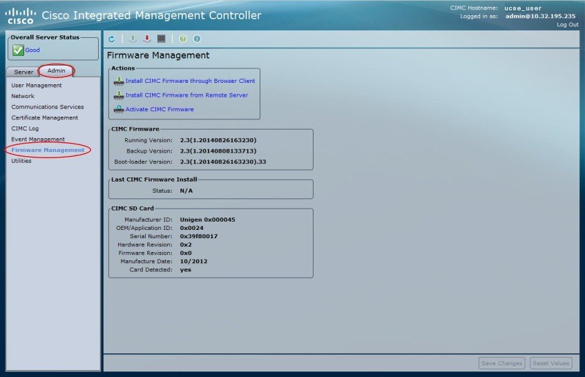 | ||||||||||||||||
| Step 3 | In the
CIMC SD
Card area, review the following information:
|
Viewing Router Information
| Step 1 | In the Navigation pane, click the Server tab. | ||||||||
| Step 2 | On the Server tab, click Summary. | ||||||||
| Step 3 | In the Router Information area of the Server Summary pane, review the following information:
|
Viewing CPU Properties
| Step 1 | In the Navigation pane, click the Server tab. | ||||||||||||||||||||
| Step 2 | On the Server tab, click Inventory. | ||||||||||||||||||||
| Step 3 | In the Inventory pane, click the CPUs tab. | ||||||||||||||||||||
| Step 4 | Review the following information for each CPU:
|
Viewing Memory Properties
| Step 1 | In the Navigation pane, click the Server tab. | ||||||||||||||||||||||||||||||
| Step 2 | On the Server tab, click Inventory. | ||||||||||||||||||||||||||||||
| Step 3 | In the Inventory pane, click the Memory tab. | ||||||||||||||||||||||||||||||
| Step 4 | In the
Memory
Summary area, review the following summary information about memory:
Displayed for the E-Series Servers and the SM E-Series NCE. Not displayed for the EHWIC E-Series NCE and the NIM E-Series NCE.
| ||||||||||||||||||||||||||||||
| Step 5 | In the
Memory
Details table, review the following detailed information about each
DIMM:
|
Viewing Power Supply Properties
| Step 1 | In the Navigation pane, click the Server tab. | ||||||||||||||
| Step 2 | On the Server tab, click Inventory. | ||||||||||||||
| Step 3 | In the Inventory pane, click the Power Supplies tab. | ||||||||||||||
| Step 4 | Review the following information for each power supply:
|
Viewing Storage Properties
 Note | This procedure is applicable to E-Series Servers and the SM E-Series NCE. This procedure is not applicable to the EHWIC E-Series NCE and the NIM E-Series NCE. |
| Step 1 | In the Navigation pane, click the Server tab. | ||
| Step 2 | On the Server tab, click RAID. | ||
| Step 3 | In the
Storage
Adapters area, review the information about the available adapter
cards.
This area contains a table listing all RAID controllers on the server that can be managed through CIMC. To view details about a particular storage device, select it in the table and view the information in the tabs below. If a particular storage device does not appear on this tab, it cannot be managed through CIMC. To view the status of an unsupported device, see the documentation for that device.
| ||
| Step 4 | In the
Storage
Adapters area, click a row to view the detailed properties of that
adapter.
The properties of the selected storage adapter appear in the tabbed menu below the Storage Adapters area. | ||
| Step 5 | Select the
Controller Info tab and review the information.
If a RAID controller is selected in the Storage Adapters table, this tab shows the following information: | ||
| Step 6 | Select the
Physical
Drive Info tab and review the information.
This tab shows the following information for the controller selected in the Storage Adapters table: | ||
| Step 7 | Select the
Virtual
Drive Info tab and review the information.
This tab shows the following information for the controller selected in the Storage Adapters table and allows you to create, edit, and clear RAID configuration: |
Viewing PCI Adapter Properties
Note | This procedure is applicable to E-Series Servers and the SM E-Series NCE. This procedure is not applicable to the EHWIC E-Series NCE and the NIM E-Series NCE. |
The server must be powered on, or the properties will not display.
| Step 1 | In the Navigation pane, click the Server tab. | ||||||||||||||
| Step 2 | On the Server tab, click Inventory. | ||||||||||||||
| Step 3 | In the Inventory pane, click the PCI Adapters tab. | ||||||||||||||
| Step 4 | In the
PCI Adapters area, review the following information for the installed PCI adapters:
|
Viewing Power Statistics
| Step 1 | In the Navigation pane, click the Server tab. | ||||||||
| Step 2 | On the Server tab, click Power Policies. | ||||||||
| Step 3 | In the Power Statistics area, review the information in the following fields:
|
Viewing the MAC Address of an Interface
You must log in as a user with admin privileges to view the system-defined interface names and the MAC address that is assigned to each interface.
Viewing the Status of CIMC Network Connections
You must log in as a user with admin privileges to view the status of the CIMC network connections; whether the link is detected (physical cable is connected to the network interface) or not detected.
| Step 1 | In the Navigation pane, click the Admin tab. | ||||||
| Step 2 | On the Admin tab, click Network. | ||||||
| Step 3 | In the Network pane, click the Network Settings tab. | ||||||
| Step 4 | In the Link State area, review the following information:
|
 Feedback