- Preface
- Overview
- Installing the Server Operating System or Hypervisor
- Managing the Server
- Managing Storage Using RAID
- Viewing Server Properties
- Viewing Server Sensors
- Managing Remote Presence
- Managing User Accounts
- Configuring Network-Related Settings
- Configuring Communication Services
- Managing Certificates
- Configuring Platform Event Filters
- Firmware Management
- Viewing Faults and Logs
- Server Utilities
- Diagnostic Tests
- Index
Configuring Communication Services
This chapter includes the following sections:
Configuring HTTP
You must log in as a user with admin privileges to perform this task.
Configuring SSH
You must log in as a user with admin privileges to configure SSH.
| Step 1 | In the Navigation pane, click the Admin tab. | ||||||||||||
| Step 2 | On the Admin tab, click Communications Services. | ||||||||||||
| Step 3 | In the
Communications Services pane, click the
Communication Services tab.
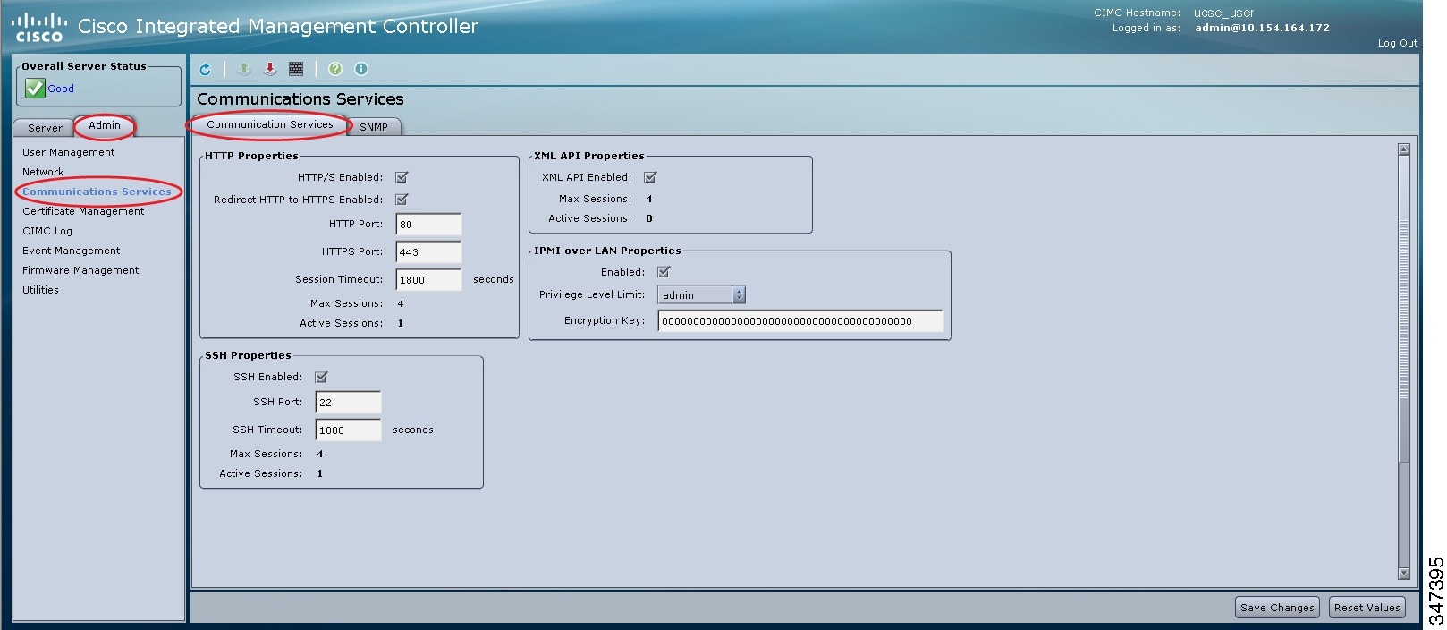 | ||||||||||||
| Step 4 | In the SSH Properties area, update the following properties:
| ||||||||||||
| Step 5 | Click Save Changes. |
Configuring the XML API
XML API for the CIMC
The Cisco CIMC XML application programming interface (API) is a programmatic interface to the CIMC for the E-Series Server. The API accepts XML documents through HTTP or HTTPS.
For detailed information about the XML API, see the CIMC XML API Programmer’s Guide for Cisco UCS E-Series Servers.
Enabling the XML API
You must log in as a user with admin privileges to perform this task.
| Step 1 | In the Navigation pane, click the Admin tab. | ||||||||
| Step 2 | On the Admin tab, click Communications Services. | ||||||||
| Step 3 | In the
Communications Services pane, click the
Communication Services tab.
| ||||||||
| Step 4 | In the XML API Properties area, update the following properties:
| ||||||||
| Step 5 | Click Save Changes. |
Configuring IPMI
IPMI over LAN
Intelligent Platform Management Interface (IPMI) defines the protocols for interfacing with a service processor embedded in a server platform. This service processor is called a Baseboard Management Controller (BMC) and resides on the server motherboard. The BMC links to a main processor and other on-board elements using a simple serial bus.
During normal operations, IPMI lets a server operating system obtain information about system health and control system hardware. For example, IPMI enables the monitoring of sensors, such as temperature, fan speeds and voltages, for proactive problem detection. If the server temperature rises above specified levels, the server operating system can direct the BMC to increase fan speed or reduce processor speed to address the problem.
Configuring IPMI over LAN
Configure IPMI over LAN when you want to manage the CIMC with IPMI messages.
You must log in as a user with admin privileges to perform this task.
| Step 1 | In the Navigation pane, click the Admin tab. | ||||||||
| Step 2 | On the Admin tab, click Communications Services. | ||||||||
| Step 3 | In the
Communications Services pane, click the
Communication Services tab.
| ||||||||
| Step 4 | In the IPMI over LAN Properties area, update the following properties:
| ||||||||
| Step 5 | Click Save Changes. |
Configuring SNMP
SNMP
The Cisco UCS E-Series Servers support the Simple Network Management Protocol (SNMP) for viewing server configuration and status and for sending fault and alert information by SNMP traps. For information on Management Information Base (MIB) files supported by CIMC, see the MIB Quick Reference for Cisco UCS at this URL: http://www.cisco.com/en/US/docs/unified_computing/ucs/sw/mib/reference/UCS_MIBRef.html.
Configuring SNMP Properties
You must log in as a user with admin privileges to perform this task.
| Step 1 | In the Navigation pane, click the Admin tab. | ||||||||||||||||||
| Step 2 | On the Admin tab, click Communications Services. | ||||||||||||||||||
| Step 3 | In the
Communications Services pane, click the
SNMP tab.
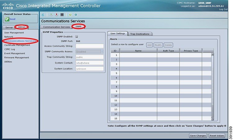 | ||||||||||||||||||
| Step 4 | In the
SNMP
Properties area, update the following properties:
| ||||||||||||||||||
| Step 5 | Click Save Changes. |
What to Do Next
Configure SNMP trap settings as described in Configuring SNMP Trap Settings.
Configuring SNMP Trap Settings
You must log in as a user with admin privileges to disable platform event alerts.
| Step 1 | In the Navigation pane, click the Admin tab. | ||||||||||||||
| Step 2 | On the Admin tab, click Communications Services. | ||||||||||||||
| Step 3 | In the
Communications Services pane, click the
SNMP tab.
| ||||||||||||||
| Step 4 | Click on Trap Destinations tab. | ||||||||||||||
| Step 5 | In the
Trap
Destinations area, you can do one of the following:
| ||||||||||||||
| Step 6 | In the
Trap
Details dialog box, complete the following fields:
| ||||||||||||||
| Step 7 | Click Save Changes. | ||||||||||||||
| Step 8 | To delete a trap destination, select the row, and then click Delete. Click OK in the confirmation prompt. |
Sending an SNMP Test Trap Message
You must log in as a user with admin privileges to perform this task.
| Step 1 | In the Navigation pane, click the Admin tab. | ||
| Step 2 | On the Admin tab, click Communications Services. | ||
| Step 3 | In the
Communications Services pane, click the
SNMP tab.
| ||
| Step 4 | Click the SNMP tab, and then click on the Trap Destinations tab. | ||
| Step 5 | In the Trap Destinations area, select the row of the desired SNMP trap destination. | ||
| Step 6 | Click
Send
SNMP Test Trap.
An SNMP test trap message is sent to the trap destination.
|
Configuring SNMP Users
You must log in as a user with admin privileges to perform this task.
| Step 1 | In the Navigation pane, click the Admin tab. | ||||||||||||||||||||
| Step 2 | On the Admin tab, click Communications Services. | ||||||||||||||||||||
| Step 3 | In the
Communications Services pane, click the
SNMP tab.
| ||||||||||||||||||||
| Step 4 | Enable SNMP if it is not enabled. In the SNMP Properties area, check the SNMP Enabled check box, and then click Save Changes. | ||||||||||||||||||||
| Step 5 | Under the User Settings tab in the Users area, do one of the following: | ||||||||||||||||||||
| Step 6 | Update the
following properties:
| ||||||||||||||||||||
| Step 7 | Click Save Changes. | ||||||||||||||||||||
| Step 8 | If you want to
delete a user, select the user and click
Delete.
Click OK in the delete confirmation prompt. |
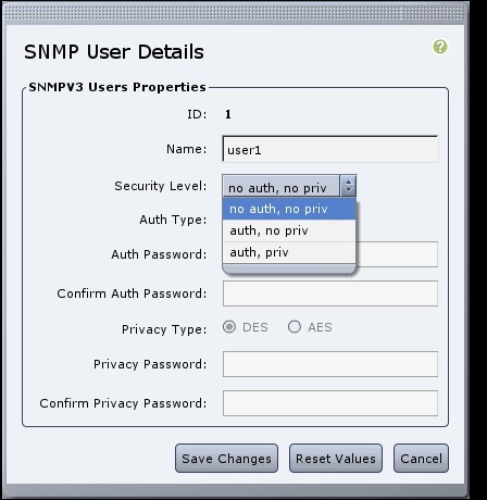
Managing SNMP Users
You must log in as a user with admin privileges to perform this task.
| Step 1 | In the Navigation pane, click the Admin tab. | ||||||||||||||||
| Step 2 | On the Admin tab, click Communications Services. | ||||||||||||||||
| Step 3 | In the
Communications Services pane, click the
SNMP tab.
| ||||||||||||||||
| Step 4 | Under the
User
Settings tab in the
Users area, update the following properties:
| ||||||||||||||||
| Step 5 | Click Save Changes. |
 Feedback