- Preface
- Overview
- Installing the Server Operating System or Hypervisor
- Managing the Server
- Managing Storage Using RAID
- Viewing Server Properties
- Viewing Server Sensors
- Managing Remote Presence
- Managing User Accounts
- Configuring Network-Related Settings
- Configuring Communication Services
- Managing Certificates
- Configuring Platform Event Filters
- Firmware Management
- Viewing Faults and Logs
- Server Utilities
- Diagnostic Tests
- Index
- RAID Options
- Configuring RAID
- Modifying the RAID Configuration
- Deleting the RAID Configuration
- Changing the Physical Drive State
- Rebuilding the Physical Drive
- Erasing the Contents of a Physical Drive
- Enabling Auto Rebuild on the Storage Controller
- Deleting the Virtual Drive
- Performing a Consistency Check on Virtual Drives
- Reconstructing the Virtual Drive Options
- Making the Virtual Drive or Physical Drive Bootable
- Installing W2K12 to Support RAID Volumes Larger than 2TB
Managing Storage Using RAID
 Note | The RAID feature is applicable to E-Series Servers and the SM E-Series NCE. The RAID feature is not applicable to the EHWIC E-Series NCE and the NIM E-Series NCE. |
This chapter includes the following sections:
- RAID Options
- Configuring RAID
- Modifying the RAID Configuration
- Deleting the RAID Configuration
- Changing the Physical Drive State
- Rebuilding the Physical Drive
- Erasing the Contents of a Physical Drive
- Enabling Auto Rebuild on the Storage Controller
- Deleting the Virtual Drive
- Performing a Consistency Check on Virtual Drives
- Reconstructing the Virtual Drive Options
- Making the Virtual Drive or Physical Drive Bootable
- Installing W2K12 to Support RAID Volumes Larger than 2TB
RAID Options
Note | The RAID feature is applicable to E-Series Servers and the SM E-Series NCE. The RAID feature is not applicable to the EHWIC E-Series NCE and the NIM E-Series NCE. |
You can choose to store the E-Series Server data files on local Redundant Array of Inexpensive Disks (RAID). The following RAID levels are supported:
-
The single-wide E-Series Server supports RAID 0 and RAID 1 levels.
-
The double-wide E-Series Server supports RAID 0, RAID 1, and RAID 5 levels.
-
The double-wide E-Series Server with the PCIe option supports RAID 0 and RAID 1 levels.
RAID 0
With RAID 0, the data is stored evenly in stripe blocks across one or more disk drives without redundancy (mirroring). The data in all of the disk drives is different.
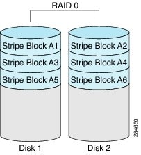
Compared to RAID 1, RAID 0 provides additional storage because both disk drives are used to store data. The performance is improved because the read and write operation occurs in parallel within the two disk drives.
However, there is no fault tolerance, error checking, hot spare, or hot-swapping. If one disk drive fails, the data in the entire array is destroyed. Because there is no error checking or hot-swapping, the array is susceptible to unrecoverable errors.
RAID 1
RAID 1 creates a mirrored set of disk drives, where the data in both the disk drives is identical, providing redundancy and high availability. If one disk drive fails, the other disk drive takes over, preserving the data.
RAID 1 also allows you to use a hot spare disk drive. The hot spare drive is always active and is held in readiness as a hot standby drive during a failover.
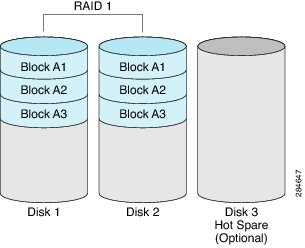
RAID 1 supports fault tolerance and hot-swapping. When one disk drive fails, you can remove the faulty disk drive and replace it with a new disk drive.
However, compared to RAID 0, there is less storage space because only half of the total potential disk space is available for storage and there is an impact on performance.
RAID 5
With RAID 5, the data is stored in stripe blocks with parity data staggered across all disk drives, providing redundancy at a low cost.
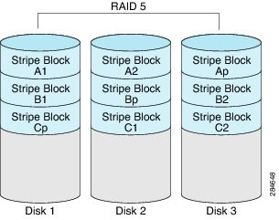
RAID 5 provides more data storage capacity than RAID 1 and better data protection than RAID 0. It also supports hot swapping; however, RAID 1 offers better performance.
Non-RAID
When the disk drives of a computer are not configured as RAID, the computer is in non-RAID mode. Non-RAID mode is also referred to as Just a Bunch of Disks or Just a Bunch of Drives (JBOD). Non-RAID mode does not support fault tolerance, error checking, hot-swapping, hot spare, or redundancy.
Summary of RAID Options
| RAID Option | Description | Advantages | Disadvantages |
|
RAID 0 |
Data stored evenly in stripe blocks without redundancy |
||
|
RAID 1 |
Mirrored set of disk drives and an optional hot spare disk drive |
||
|
RAID 5 |
Data stored in stripe blocks with parity data staggered across all disk drives |
||
|
Non-RAID |
Disk drives not configured for RAID Also referred to as JBOD |
Configuring RAID
Note | The RAID feature is applicable to E-Series Servers and the SM E-Series NCE. The RAID feature is not applicable to the EHWIC E-Series NCE and the NIM E-Series NCE. |
Use this procedure to configure the RAID level, strip size, host access privileges, drive caching, and initialization parameters on a virtual drive. You can also use this procedure to designate the drive as a hot spare drive and to make the drive bootable.
Modifying the RAID Configuration
Note | The RAID feature is applicable to E-Series Servers and the SM E-Series NCE. The RAID feature is not applicable to the EHWIC E-Series NCE and the NIM E-Series NCE. |
Use this procedure to enable or disable auto rebuild on the storage controller.
| Step 1 | In the Navigation pane, click the Server tab. | ||||||
| Step 2 | On the Server tab, click RAID. | ||||||
| Step 3 | In the tabbed menu of the
Storage
Cards area, click the
Virtual Drive Info tab.
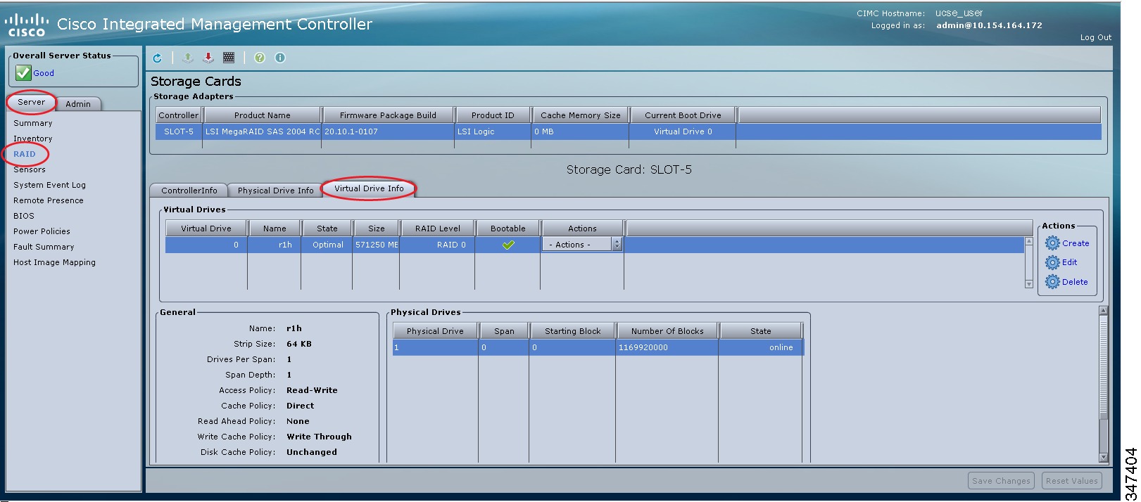 | ||||||
| Step 4 | In the
Actions area of the
Virtual
Drive Info tab, click
Edit.
The Modify RAID Configuration dialog box appears. Modify the following as appropriate:
|
Deleting the RAID Configuration
Note | The RAID feature is applicable to E-Series Servers and the SM E-Series NCE. The RAID feature is not applicable to the EHWIC E-Series NCE and the NIM E-Series NCE. |
Use this procedure to clear all RAID or foreign configurations.
| Step 1 | In the Navigation pane, click the Server tab. | ||||||||||||
| Step 2 | On the Server tab, click RAID. | ||||||||||||
| Step 3 | In the tabbed menu of the
Storage
Cards area, click the
Virtual Drive Info tab.
| ||||||||||||
| Step 4 | In the
Actions area of the
Virtual
Drive Info tab, click
Delete.
The Clear Configurations dialog box appears. Do the following as appropriate:
|
Changing the Physical Drive State
Note | The RAID feature is applicable to E-Series Servers and the SM E-Series NCE. The RAID feature is not applicable to the EHWIC E-Series NCE and the NIM E-Series NCE. |
| Step 1 | In the Navigation pane, click the Server tab. |
| Step 2 | On the Server tab, click RAID. |
| Step 3 | In the tabbed
menu of the
Storage
Cards area, click the
Physical Drive Info tab.
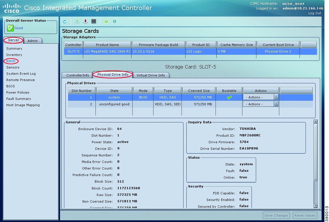 |
| Step 4 | From the Actions column in the Physical Drives pane, choose one of the following from the Change State To list: |
| Step 5 | Click OK to confirm. |
Rebuilding the Physical Drive
Note | The RAID feature is applicable to E-Series Servers and the SM E-Series NCE. The RAID feature is not applicable to the EHWIC E-Series NCE and the NIM E-Series NCE. |
Use this procedure to manually start the rebuild process on the physical drive.
| Step 1 | In the Navigation pane, click the Server tab. | ||
| Step 2 | On the Server tab, click RAID. | ||
| Step 3 | In the tabbed
menu of the
Storage
Cards area, click the
Physical Drive Info tab.
| ||
| Step 4 | From the
Actions
column in the
Physical
Drives pane, choose
Rebuild from the drop-down list, and then click
OK to confirm.
The Rebuild process takes a few hours to complete.
| ||
| Step 5 | To view the progress of the Rebuild process, see the Rebuilding Progress and the Rebuilding Time Elapsed fields in the General area. | ||
| Step 6 | To stop the Rebuild process, click the Abort button, which is located next to the Rebuilding Progress field in the General area, and then click OK to confirm. |
Erasing the Contents of a Physical Drive
Note | The RAID feature is applicable to E-Series Servers and the SM E-Series NCE. The RAID feature is not applicable to the EHWIC E-Series NCE and the NIM E-Series NCE. |
Use this procedure to erase all of the contents of a physical drive and set it to zero.
| Step 1 | In the Navigation pane, click the Server tab. |
| Step 2 | On the Server tab, click RAID. |
| Step 3 | In the tabbed
menu of the
Storage
Cards area, click the
Physical Drive Info tab.
|
| Step 4 | From the
Actions
column in the
Physical
Drives pane, choose
Erase
from the drop-down list, and then click
OK to confirm.
The Erase process takes a few hours to complete. |
| Step 5 | To view the progress of the Erase process, see the Erasing Progress and the Erasing Time Elapsed fields in the General area. |
| Step 6 | To stop the Erase process, click the Abort button, which is located next to the Erasing Progress field in the General area, and then click OK to confirm. |
Enabling Auto Rebuild on the Storage Controller
Note | The RAID feature is applicable to E-Series Servers and the SM E-Series NCE. The RAID feature is not applicable to the EHWIC E-Series NCE and the NIM E-Series NCE. |
Use this procedure to rebuild a disk drive automatically. If one of the disk drives that is configured with RAID becomes degraded, and a new drive is plugged it, the rebuild process on the new drive starts automatically.
| Step 1 | In the Navigation pane, click the Server tab. | ||
| Step 2 | On the Server tab, click RAID. | ||
| Step 3 | In the
Storage
Adapters area, select the storage card.
If the server is powered on, the resources of the selected storage adapter appear in the tabbed menu in the Storage Cards area. | ||
| Step 4 | In the tabbed menu of the
Storage
Cards area, click the
Virtual Drive Info tab.
| ||
| Step 5 | In the
Actions area of the
Virtual
Drive Info tab, click
Edit.
The Modify RAID Configuration dialog box appears. | ||
| Step 6 | If the
Enable
Auto Rebuild button appears, click the button to make the
Disable
Auto Rebuild button appear.
The Disable Auto Rebuild button indicates that auto rebuild is enabled.
|
Deleting the Virtual Drive
Note | The RAID feature is applicable to E-Series Servers and the SM E-Series NCE. The RAID feature is not applicable to the EHWIC E-Series NCE and the NIM E-Series NCE. |
| Step 1 | In the Navigation pane, click the Server tab. |
| Step 2 | On the Server tab, click RAID. |
| Step 3 | In the tabbed menu of the
Storage
Cards area, click the
Virtual Drive Info tab.
|
| Step 4 | From the Actions column in the Virtual Drives area, choose the Delete option. |
| Step 5 | Click OK to confirm. |
Performing a Consistency Check on Virtual Drives
Note | The RAID feature is applicable to E-Series Servers and the SM E-Series NCE. The RAID feature is not applicable to the EHWIC E-Series NCE and the NIM E-Series NCE. |
Use this procedure to perform a consistency check on virtual drives. This can be one of the following:
| Step 1 | In the Navigation pane, click the Server tab. |
| Step 2 | On the Server tab, click RAID. |
| Step 3 | In the tabbed menu of the
Storage
Cards area, click the
Virtual Drive Info tab.
|
| Step 4 | From the
Actions column in the
Virtual
Drives area, choose the
Consistency Check option, and then click
OK to confirm.
The Consistency Check process takes a few hours to complete. |
| Step 5 | To view the progress of the Consistency Check process, see the Consistency Check Progress and the Consistency Check Time Elapsed fields in the General area. |
| Step 6 | To stop the Consistency Check process, click the Abort button, which is located next to the Consistency Check Progress field in the General area, and then click OK to confirm. |
Reconstructing the Virtual Drive Options
Note | The RAID feature is applicable to E-Series Servers and the SM E-Series NCE. The RAID feature is not applicable to the EHWIC E-Series NCE and the NIM E-Series NCE. |
To migrate (reconstruct) the virtual drive to a new RAID level, you might need to add or remove physical drives. When you add or remove physical drives, the size of the virtual drive is either retained or increased.
You can retain or increase the size of the virtual drive, but you cannot decrease its size. For example, if you have two physical drives with RAID 0, you cannot migrate to RAID 1 with the same number of drives. Because with RAID 1, a mirrored set of disk drives are created, which reduces the size of the virtual drive to half of what it was before, which is not supported.
Note | The virtual drive reconstruction process might take several hours to complete. You can continue to use the system during the reconstruction process. |
Options for Retaining the Size of the Virtual Drive
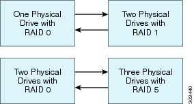
The following table lists the options that retain the size of the virtual drive and provides information about how many physical drives you must add or remove to migrate the virtual drive to a specific RAID level.
|
From: |
Migrate to: |
Add or Remove Disks |
|---|---|---|
|
One physical drive with RAID 0 |
Two physical drives with RAID 1 |
Add one disk. |
|
Two physical drives with RAID 1 |
One physical drive with RAID 0 |
Remove one disk. |
|
Two physical drives with RAID 0 |
Three physical drives with RAID 5 |
Add one disk. |
|
Three physical drives with RAID 5 |
Two physical drives with RAID 0 |
Remove one disk. |
Options for Increasing the Size of the Virtual Drive
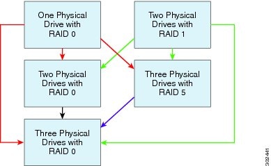
The following table lists the options that increase the size of the virtual drive and provides information about how many physical drives you must add or remove to migrate the virtual drive to a specific RAID level.
|
From: |
Migrate to: |
Add or Remove Disks |
|---|---|---|
|
One physical drive with RAID 0 See the red arrows in the figure. |
Two physical drives with RAID 0 |
Add one disk. |
|
Three physical drives with RAID 5 |
Add two disks. |
|
|
Three physical drives with RAID 0 |
Add two disks. |
|
|
Two physical drives with RAID 1 See the green arrows in the figure. |
Two physical drives with RAID 0 |
— |
|
Three physical drives with RAID 5 |
Add one disk. |
|
|
Three physical drives with RAID 0 |
Add one disk. |
|
|
Two physical drives with RAID 0 See the black arrow in the figure. |
Three physical drives with RAID 0 |
Add one disk. |
|
Three physical drives with RAID 5 See the purple arrow in the figure. |
Three physical drives with RAID 0 |
— |
Reconstructing the Virtual Drive
Note | The RAID feature is applicable to E-Series Servers and the SM E-Series NCE. The RAID feature is not applicable to the EHWIC E-Series NCE and the NIM E-Series NCE. |
Use this procedure to migrate (reconstruct) the virtual drive to a new RAID level.
| Step 1 | In the Navigation pane, click the Server tab. | ||||||||||||||||||||
| Step 2 | On the Server tab, click RAID. | ||||||||||||||||||||
| Step 3 | In the tabbed menu of the
Storage
Cards area, click the
Virtual Drive Info tab.
| ||||||||||||||||||||
| Step 4 | From the
Actions column in the
Virtual
Drives area, choose the
Reconstruct option.
The Reconstruct Virtual Drive dialog box appears. 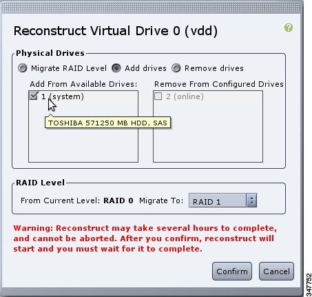 | ||||||||||||||||||||
| Step 5 | Complete the
following as appropriate:
The Reconstruct process takes a few hours to complete. | ||||||||||||||||||||
| Step 6 | To view the progress of the Reconstruct process, see the Reconstruct Progress and the Reconstruct Time Elapsed fields in the General area. |
Making the Virtual Drive or Physical Drive Bootable
Note | The RAID feature is applicable to E-Series Servers and the SM E-Series NCE. The RAID feature is not applicable to the EHWIC E-Series NCE and the NIM E-Series NCE. |
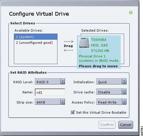
When you configure RAID, the Configure Virtual Drive dialog box has a check box that allows you to make the disk drive bootable. If you did not check the Set this Virtual Drive Bootable check box during the RAID configuration process, you can use this procedure to make the disk drive bootable.
Installing W2K12 to Support RAID Volumes Larger than 2TB
On a UCS-E160D-M2 series server, if you want to run Windows with more than 2 TB of hard drive space installed, follow the procedure explained in this section. There are two ways you can install W2K12: Using Legacy BIOS or using UEFI:
- Installing W2K12 Using Legacy BIOS to Support RAID Volumes Larger than 2TB
- Installing W2K12 using UEFI to Support RAID Volumes Larger than 2TB
Installing W2K12 Using Legacy BIOS to Support RAID Volumes Larger than 2TB
This workaround shows how to install W2K12 using legacy BIOS to support RAID volumes larger than 2TB. The workaround involves the following major tasks:
- Configure all the drives in ‘Unconfigured Good’ state.
-
Configure a Virtual Drive 0 (VD0) using the first hard disk and put it in RAID 0. W2K12 will be installed on VD0.
-
Configure a Virtual Drive 1(VD1) using the remaining hard disks and put it in RAID 0. Use W2K12 to convert this volume to GPT so that it can access the entire storage.
The detailed procedure is explained below:
| Step 1 | Configure all the drives in ‘Unconfigured Good’ state. Refer Changing the Physical Drive State |
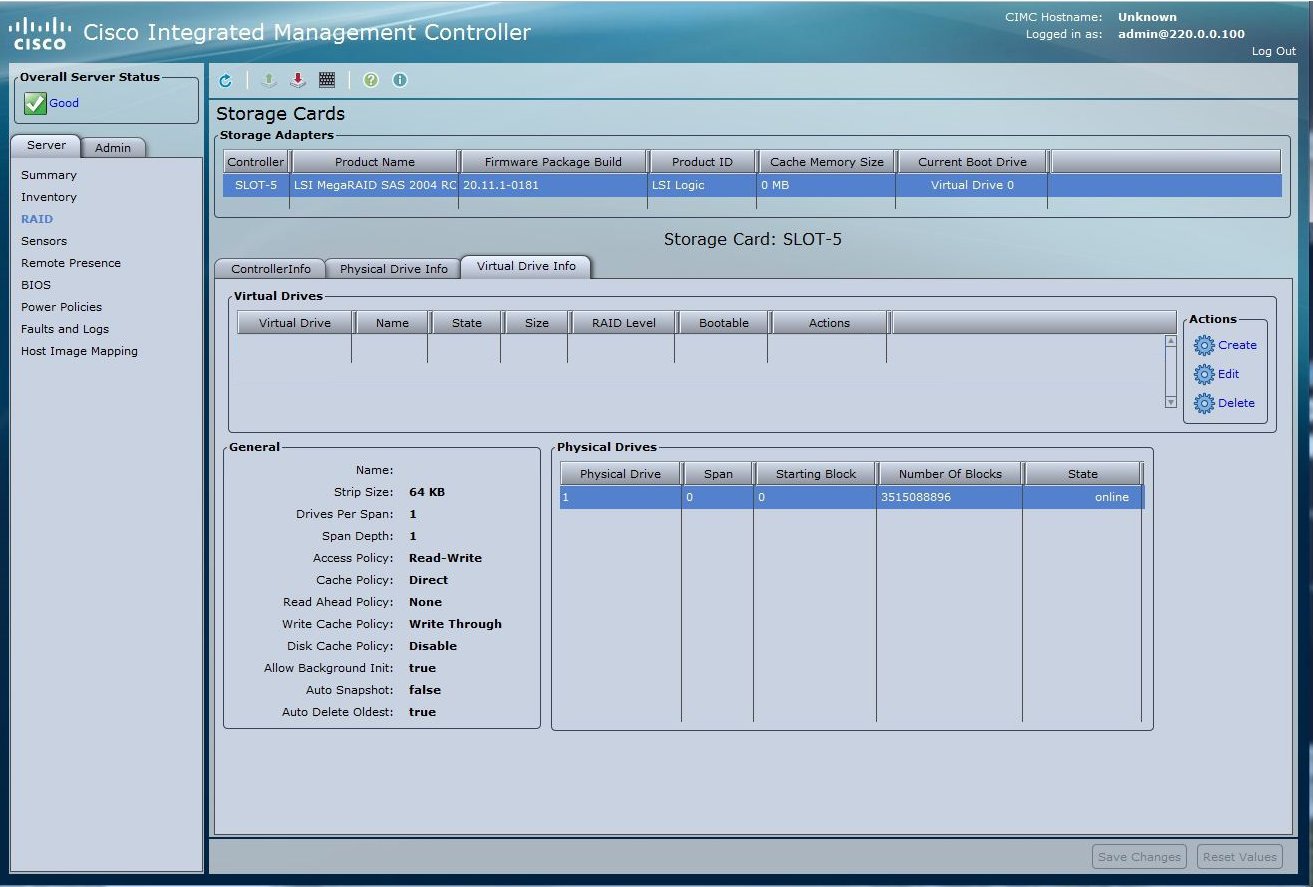
| Step 2 | In the tabbed menu of the
Storage
Cards area, click the
Virtual Drive Info tab.
 |
| Step 3 | In the Actions
area of the Virtual Drive Info tab, click
Create. The
Configure Virtual Drive dialog box appears:
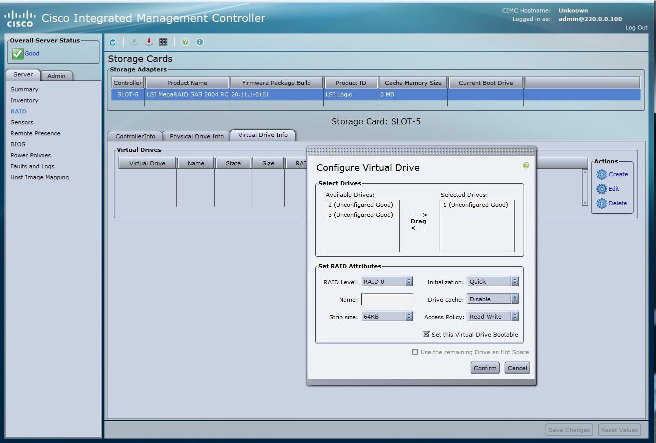 |
| Step 4 | Select drive 1 from the Available Devices and drag to Selected Devices. |
| Step 5 | Click Confirm. You have now created Virtual Drive 0. |
| Step 6 | In the Actions area of the Virtual Drive Info tab, click Create. The Configure Virtual Drive dialog box appears. |
| Step 7 | Select the
remaining drives from the Available Devices and drag to Selected Devices.
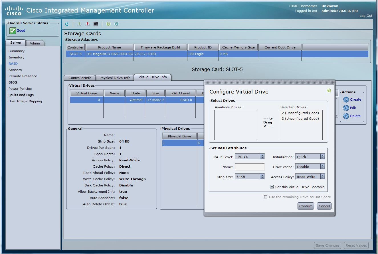 |
| Step 8 | Click
Confirm. You have now created Virtual Drive 1.
Verify the Virtual Drives.
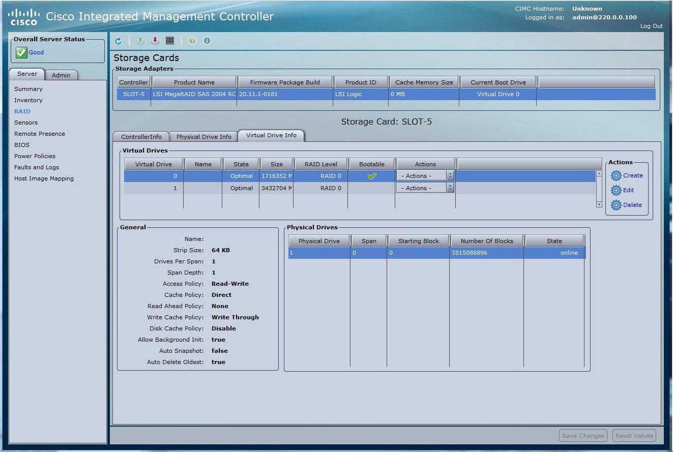 |
| Step 9 | Use Host Image
Mapping or vKVM to install W2K12 on Virtual Drive 0.
|
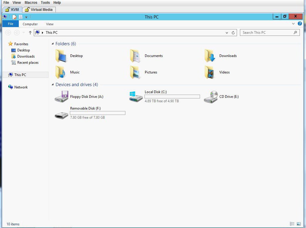
| Step 10 | After W2K12
installation, log in and check the status of volume.
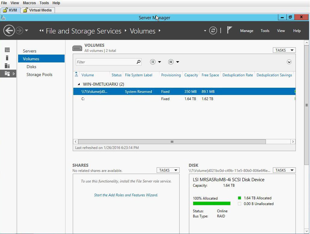 |
| Step 11 | Check the
storage size of C drive.
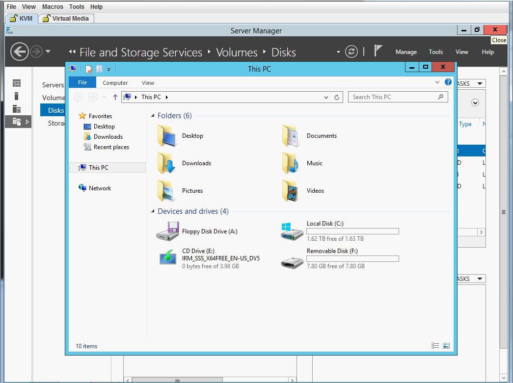 |
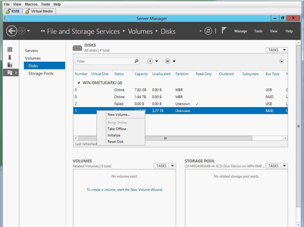
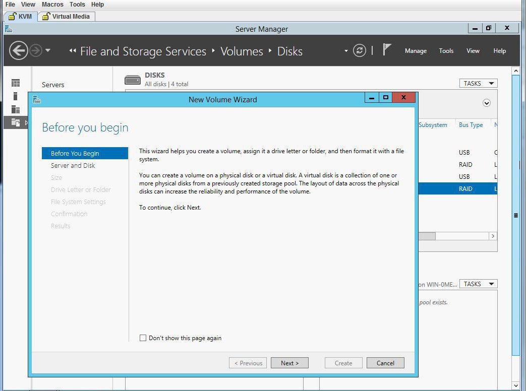
| Step 12 | Go to Disk
and create a new volume using the Virtual Drive 1. Select Virtual Drive 1 and
right click on it. Click
New
Volume. The New Volume wizard appears. This wizard helps you create
a volume, assign it a drive letter, and then format it with a file system.
  |
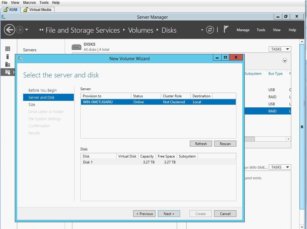
| Step 13 | Select the
server and disk, and click
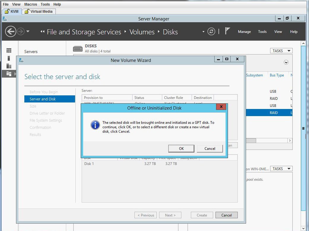
Next. You will be prompted with a dialog box.
 |
| Step 14 | Click
OK.
 |
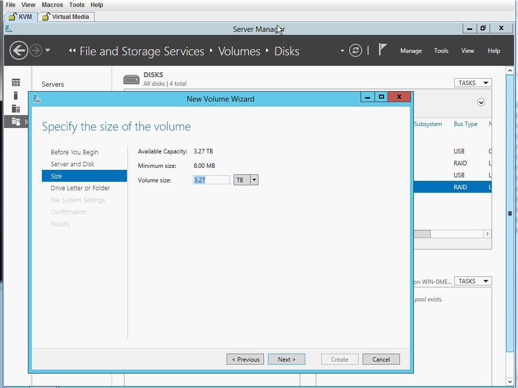
| Step 15 | Specify the
size of the disk volume.
 |
| Step 16 | Assign the
volume to a drive letter.
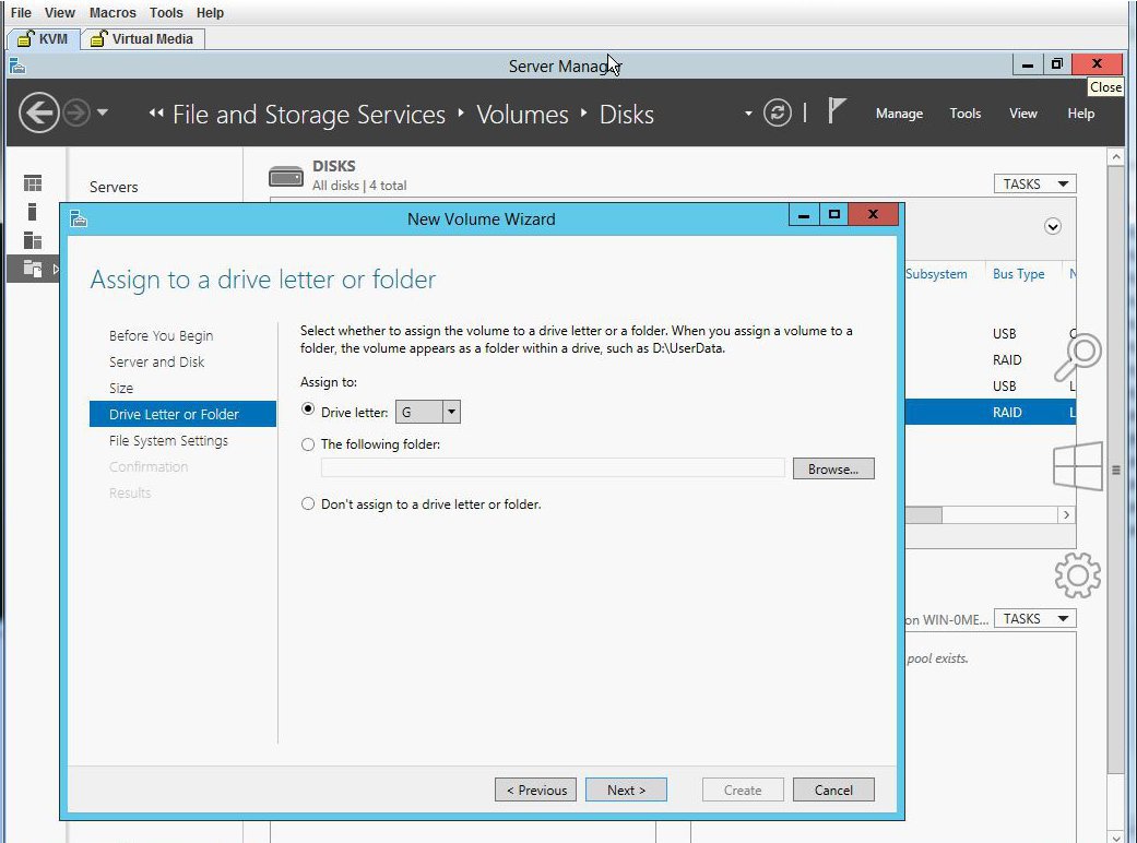 |
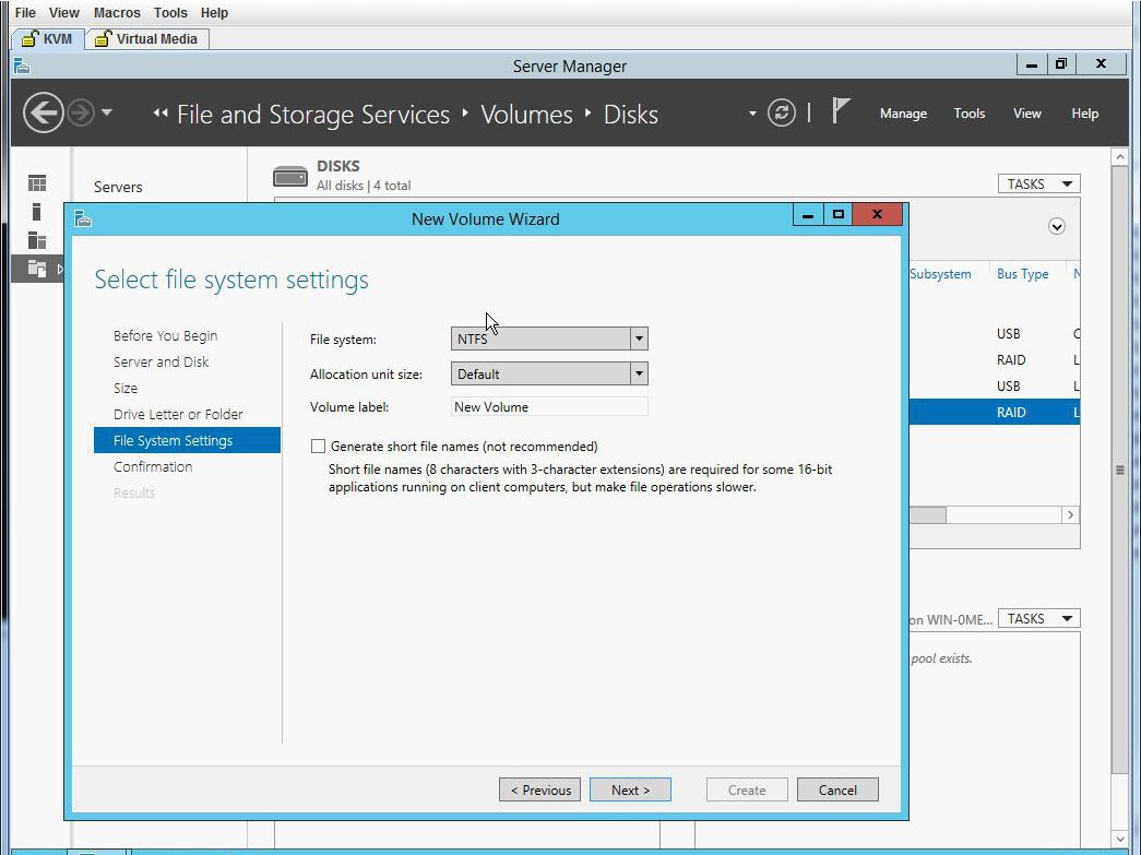
| Step 17 | Select the
File System Settings.
 |
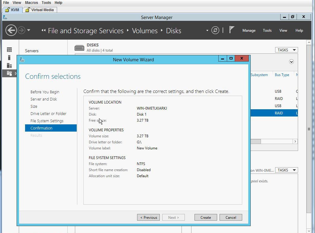
| Step 18 | Confirm the
selections and click
Create. A completion message appears. Click
Close.
 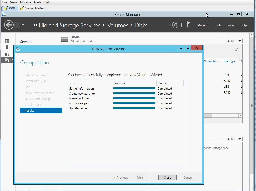 |
| Step 19 | Verify the new
volume created and W2K12 recognizes the remaining storage.
 |
Installing W2K12 using UEFI to Support RAID Volumes Larger than 2TB
This workaround shows how to install W2k12 using UEFI to support RAID volumes larger than 2TB. The workaround involves the following major tasks:
-
Configure all the drives in ‘Unconfigured Good’ state.
- Configure a Virtual Drive 0 (VD0) using all the hard disks and put it in RAID 0. W2K12 will be installed on VD0 and the OS will recognize the entire storage capacity.
-
Enter BIOS setup and configure it to boot using UEFI.
-
Map W2K12 ISO using Host Image Mapping or Virtual Media using vKVM.
-
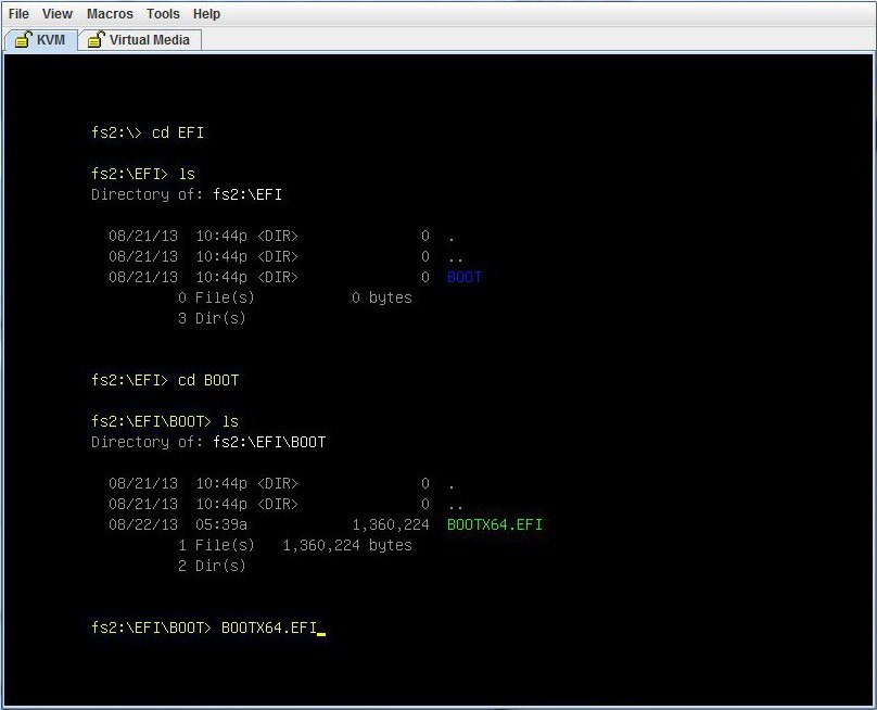
Boot UCS-E module into EFI shell.
-
From the EFI shell, navigate to the ISO and boot BOOTX64.EFI.
-
Install W2K12. During W2K12 installation, the server will reboot.
-
Enter BIOS setup and change the 'UCSM boot order rules' from 'Strict' to 'Loose'. This change disallows CIMC to override the BIOS boot order. The BIOS boot order will be used instead of the CIMC boot order.
-
Move 'Windows Boot Manager' to top of the boot order. W2K12 should now automatically boot and recognize the entire storage.
The detailed procedure is explained below:
| Step 1 | Configure all the drives in ‘Unconfigured Good’ state. Refer Changing the Physical Drive State |
| Step 2 | Configure a Virtual Drive 0 (VD0) using all the hard disks and put it in RAID 0. W2K12 will be installed on VD0 and the OS will recognize the entire storage capacity. Refer the procedure explained in Installing W2K12 Using Legacy BIOS to Support RAID Volumes Larger than 2TB |
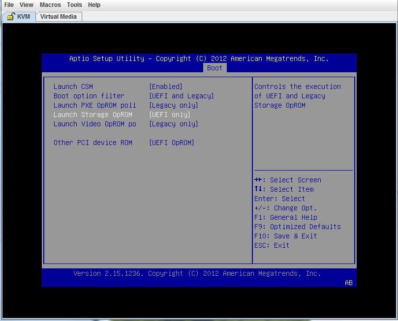
| Step 3 | Enter BIOS setup and change storage to 'UEFI only'. |
| Step 4 | Map ISO using virtual media or use the host image mapping. Configure 'CD/DVD' as the first bootable device using CIMC GUI. |
| Step 5 | Power cycle the server. Press F2 while booting up. Enter BIOS setup and select one time boot to EFI shell. |
| Step 6 | Boot from the
EFI shell. Locate the file system number (fs#) that contains the 'Removable
CDRom'.
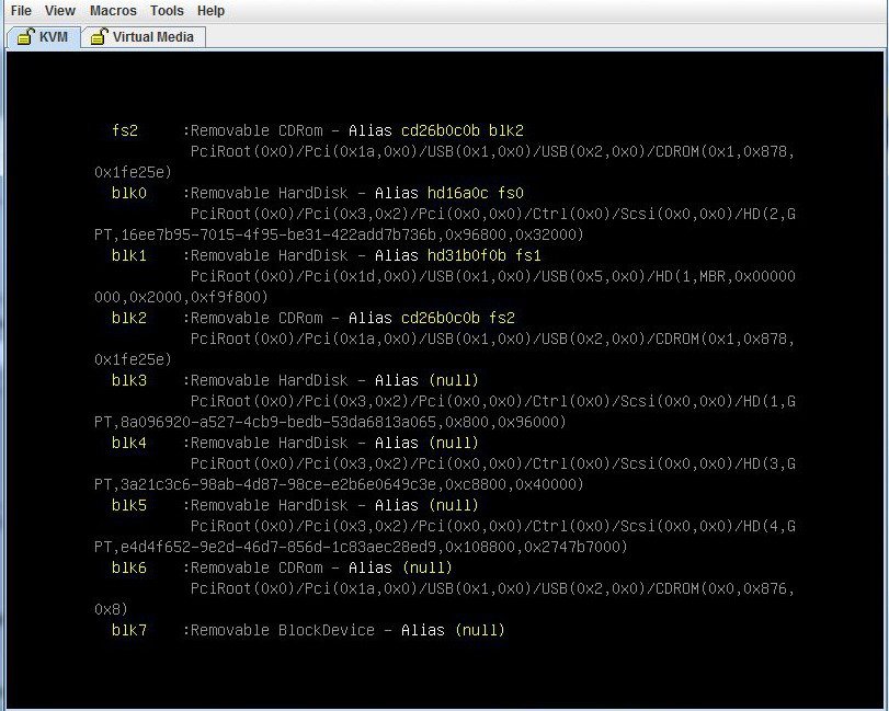  |
| Step 7 | Choose W2K12
Standard Evaluation Server with GUI. Click
Next
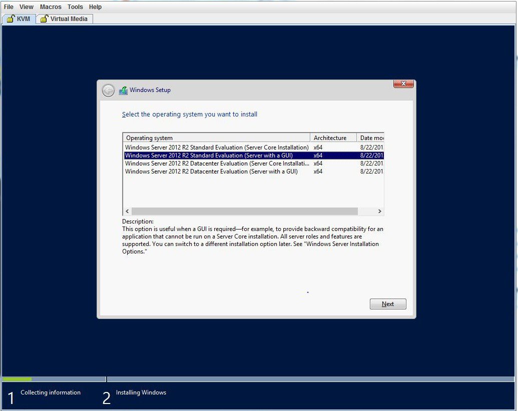 |
| Step 8 | Select the
drive you want to install Windows. Click
Next.
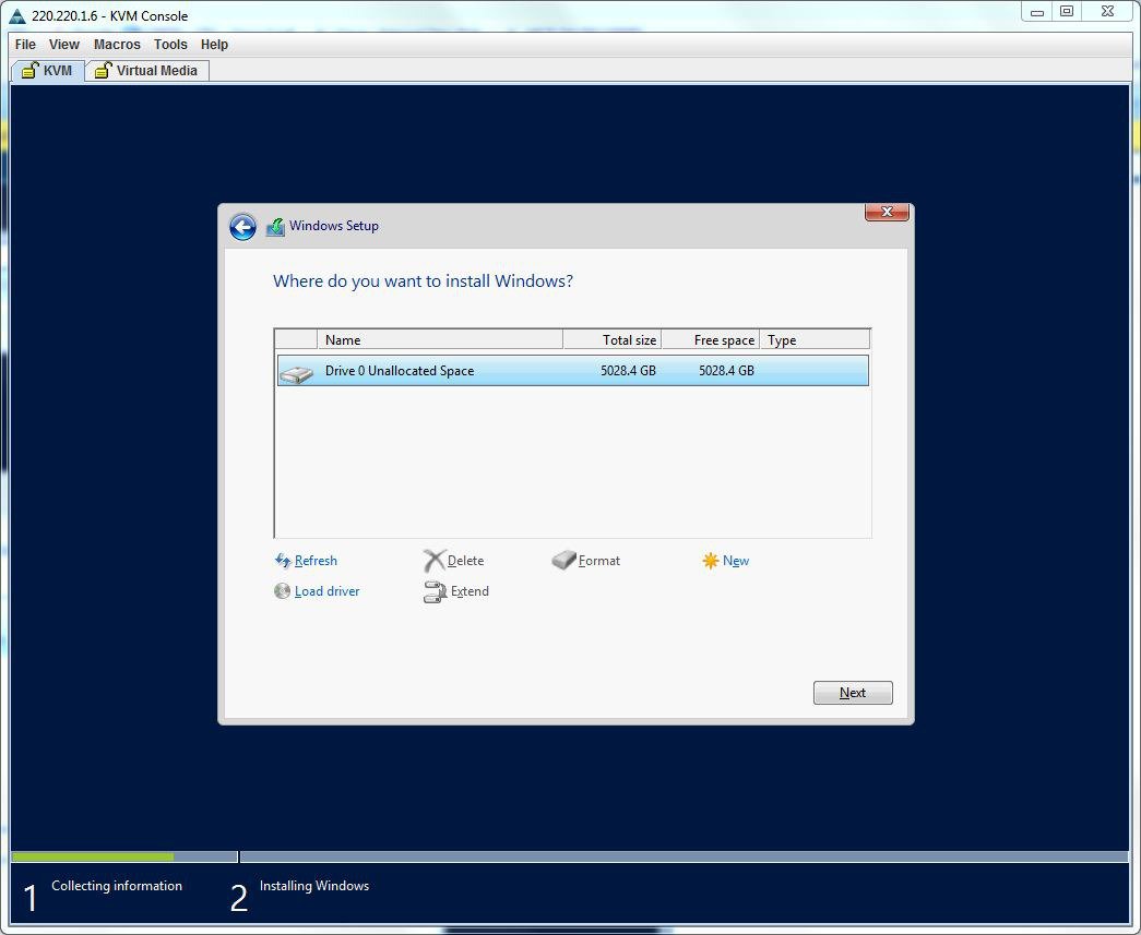 |
| Step 9 | Wait till the
installation completes.
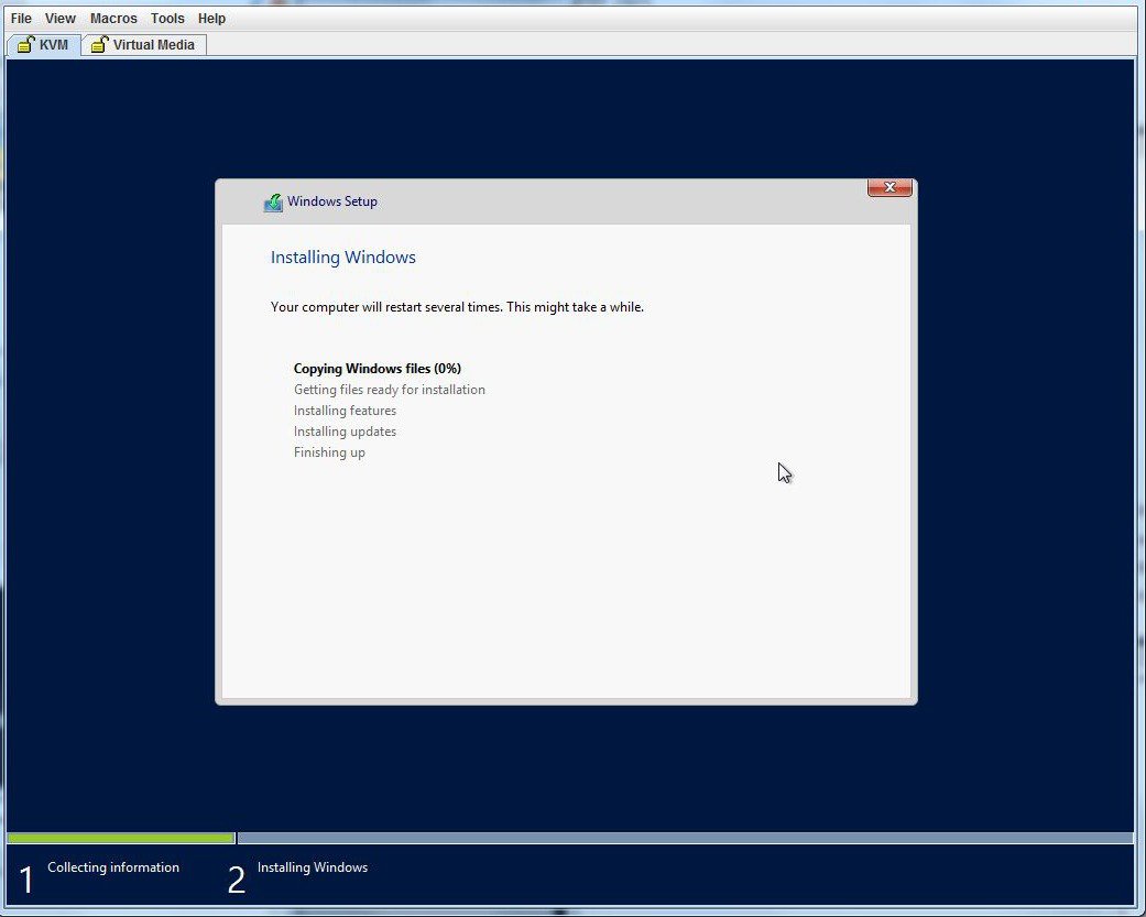 |
| Step 10 | After the
installation, enter BIOS setup ( press F2) or BIOS Boot Menu (press F6) and
boot using Windows Boot Manager. You may find several Windows Boot Manager.
Select the one that works.
 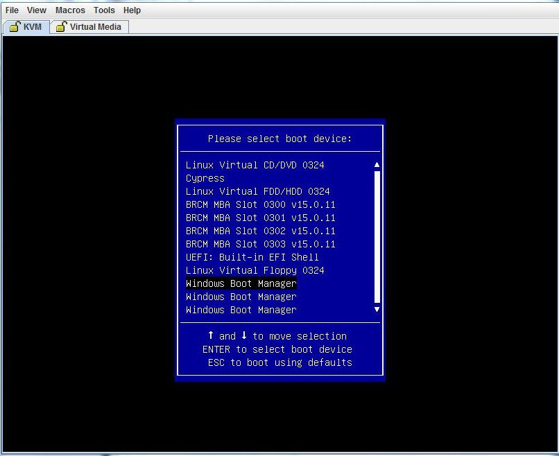 |
| Step 11 | After W2K12
boots up, verify the GPT volume using the
diskpart command.
 |
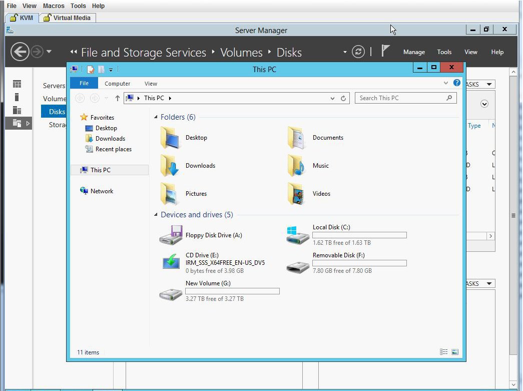
| Step 12 | Verify W2K12
recognizes the entire volume.
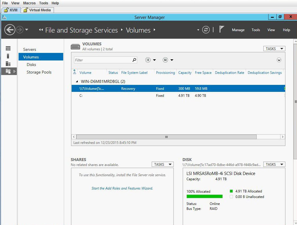 |
| Step 13 | Verify W2K12
recognizes the full storage of C drive.
 |
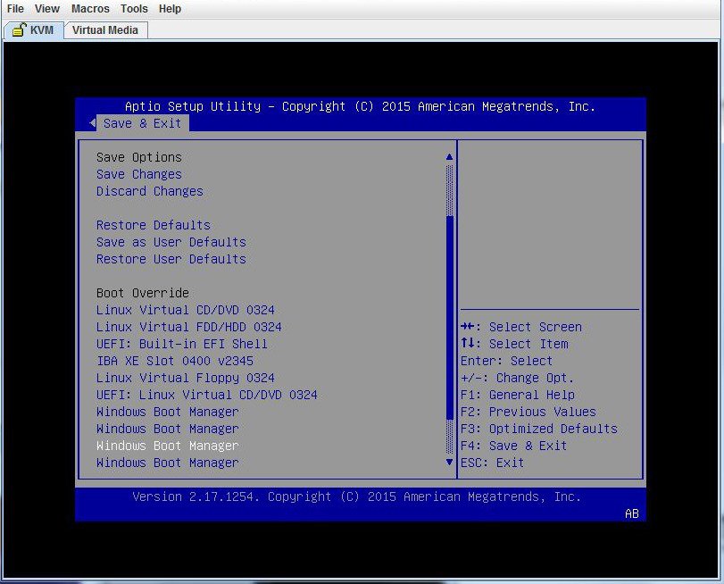
| Step 14 | To make W2K12
boot automatically, enter BIOS and make the following changes:
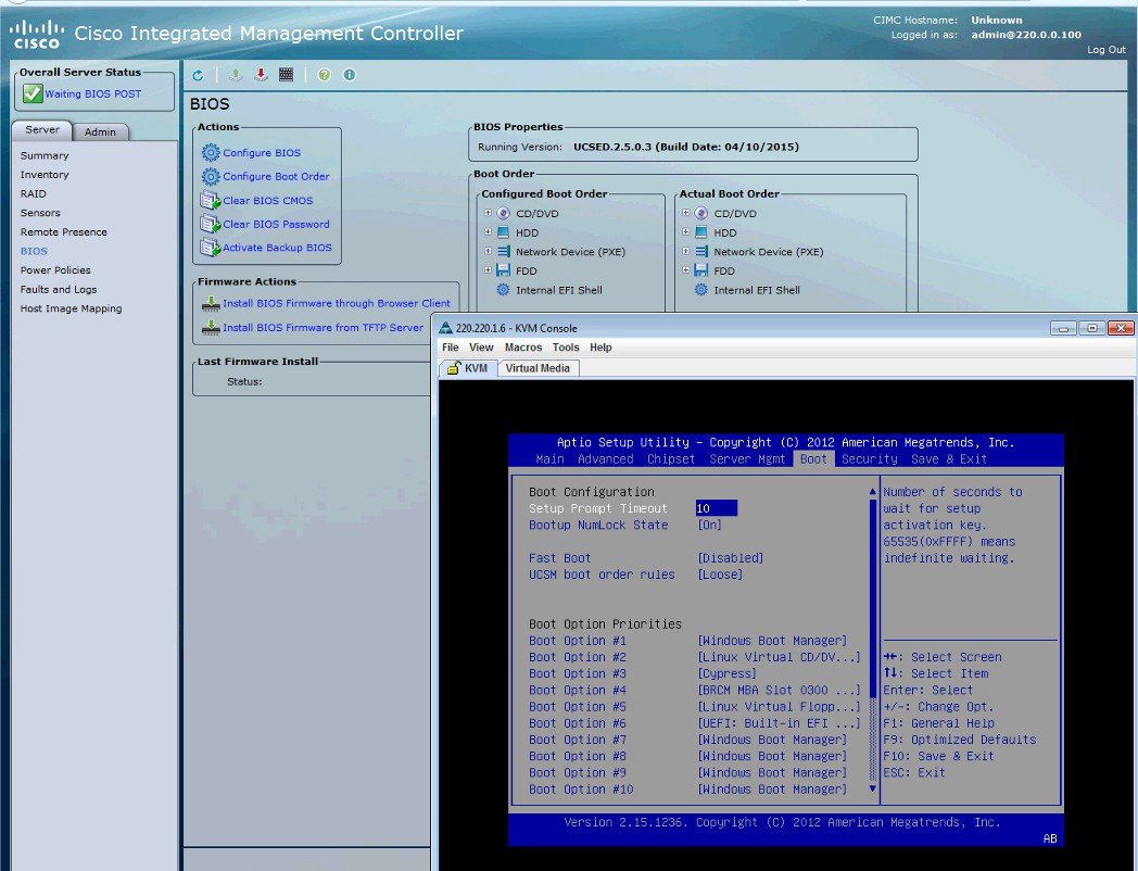 |
| Step 15 | Finally, save your changes and exit BIOS setup. |
 Feedback