- Overview of Server Firmware Requirements
- GPU Card Configuration Rules
- Requirement For All Supported GPUs: Memory-Mapped I/O Greater than 4 GB
- Installing a GPU Card (Less Than 250 W)
- Installing a High-Power GPU Card and Server Conversion Kit
- Using NVIDIA GRID License Server For M-Series GPUs
- NVIDIA GRID License Server Overview
- Registering Your Product Activation Keys With NVIDIA
- Downloading the GRID Software Suite
- Installing NVIDIA GRID License Server Software
- Installing GRID Licenses From the NVIDIA Licensing Portal to the License Server
- Managing GRID Licenses
- Switching Between Compute Mode and Graphics Mode
- Installing Drivers to Support the GPU Cards
GPU Card Installation
This appendix contains the following topics:
- Overview of Server Firmware Requirements
- GPU Card Configuration Rules
- Requirement For All Supported GPUs: Memory-Mapped I/O Greater than 4 GB
- Installing a GPU Card (Less Than 250 W)
- Installing a High-Power GPU Card and Server Conversion Kit
- Using NVIDIA GRID License Server For M-Series GPUs
- Installing Drivers to Support the GPU Cards
For each supported GPU card, see the required installation procedures in Table D-1 :
|
|
|
|---|---|
Overview of Server Firmware Requirements
Table D-2 lists the minimum server firmware versions for the supported GPU cards.
|
|
|
|---|---|
GPU Card Configuration Rules
The rules for configuring the server with GPUs differ, depending on the server version and other factors. Observe the following rules when populating GPUs in the server:
- All GPU cards require two CPUs and two power supplies in the server. 1400 W power supplies are recommended. Use the UCS power calculator at the following link to determine the power needed based on your server configuration: http://ucspowercalc.cisco.com
- For riser 1, use version 1A (slot 2) for GPU cards. This server can be ordered with one of three PCIe riser 1 versions. GPU cards are not supported in version 1B (UCSC-PCI-1B-240M4) or 1C (UCSC-PCI-1C-240M4).
- GPU cards are also supported in PCIe riser 2, slot 5.

–![]() You can mix GRID K1 and K2 GPU cards in the same server.
You can mix GRID K1 and K2 GPU cards in the same server.
–![]() Do not mix GRID GPU cards with Tesla GPU cards in the same server.
Do not mix GRID GPU cards with Tesla GPU cards in the same server.
–![]() Do not mix different models of Tesla GPU cards in the same server.
Do not mix different models of Tesla GPU cards in the same server.
- NVIDIA K-Series and M-Series GPUs can support only less-than 1 TB memory in the server.
- NVIDIA P-Series GPUs can support 1 TB or more memory in the server.
- AMD FirePro S7150 X2 can support only less-than 1 TB memory in the server.
- Table D-3 shows the rules for populating GPU cards in the server.
|
|
|
|
|---|---|---|

Note![]() You can install a GPU card and a Cisco UCS VIC in the same riser. When you install a GPU card in slot 2, NCSI support in riser 1A automatically moves to slot 1. When you install a GPU card in slot 5, NCSI support in riser 2 automatically moves to slot 4.
You can install a GPU card and a Cisco UCS VIC in the same riser. When you install a GPU card in slot 2, NCSI support in riser 1A automatically moves to slot 1. When you install a GPU card in slot 5, NCSI support in riser 2 automatically moves to slot 4.
Requirement For All Supported GPUs: Memory-Mapped I/O Greater than 4 GB
All supported GPU cards require enablement of the BIOS setting that allows greater than 4 GB of memory-mapped I/O (MMIO).
Standalone Server
If the server is used in standalone mode, this BIOS setting is enabled by default:
Advanced > PCI Configuration > Memory Mapped I/O Above 4 GB [Enabled]
If you need to change this from a different setting, enter the BIOS Setup Utility by pressing F2 when prompted during bootup.
Cisco UCS Manager Controlled Server
If the server is integrated with Cisco UCS Manager and controlled by a service profile, this setting is enabled by default in the service profile when a GPU is present.
To change this setting manually, use the following procedure.
Step 1![]() Refer to the Cisco UCS Manager configuration guide (GUI or CLI) for your release for instructions on configuring service profiles:
Refer to the Cisco UCS Manager configuration guide (GUI or CLI) for your release for instructions on configuring service profiles:
Cisco UCS Manager Configuration Guides
Step 2![]() Refer to the chapter on Configuring Server-Related Policies > Configuring BIOS Settings.
Refer to the chapter on Configuring Server-Related Policies > Configuring BIOS Settings.
Step 3![]() In the section of your profile for PCI Configuration BIOS Settings, set
In the section of your profile for PCI Configuration BIOS Settings, set Memory Mapped IO Above 4GB Config to one of the following:
- Disabled—Does not map 64-bit PCI devices to 64 GB or greater address space.
- Enabled —Maps I/O of 64-bit PCI devices to 64 GB or greater address space.
- Platform Default —The policy uses the value for this attribute contained in the BIOS defaults for the server. Use this only if you know that the server BIOS is set to use the default enabled setting for this item.
Note![]() Cisco UCS Manager pushes BIOS configuration changes through a BIOS policy or default BIOS settings to the Cisco Integrated Management Controller (CIMC) buffer. These changes remain in the buffer and do not take effect until the server is rebooted.
Cisco UCS Manager pushes BIOS configuration changes through a BIOS policy or default BIOS settings to the Cisco Integrated Management Controller (CIMC) buffer. These changes remain in the buffer and do not take effect until the server is rebooted.
Installing a GPU Card (Less Than 250 W)
Use this section to install or replace a GPU card that draws less than 250 W power (no server conversion kit is required). Use this section to install the following GPUs:
Note![]() If you are installing an NVIDIA Tesla M10 GPU, you must install GRID licenses to use the GRID features. See Using NVIDIA GRID License Server For M-Series GPUs.
If you are installing an NVIDIA Tesla M10 GPU, you must install GRID licenses to use the GRID features. See Using NVIDIA GRID License Server For M-Series GPUs.
For high-power GPU cards, see Installing a High-Power GPU Card and Server Conversion Kit.
Step 1![]() Shut down and power off the server as described in Shutting Down and Powering Off the Server.
Shut down and power off the server as described in Shutting Down and Powering Off the Server.
Step 2![]() Slide the server out the front of the rack far enough so that you can remove the top cover. You might have to detach cables from the rear panel to provide clearance.
Slide the server out the front of the rack far enough so that you can remove the top cover. You might have to detach cables from the rear panel to provide clearance.
Step 3![]() Remove the top cover as described in Removing and Replacing the Server Top Cover.
Remove the top cover as described in Removing and Replacing the Server Top Cover.
Step 4![]() Remove the PCIe risers and any existing GPU card:
Remove the PCIe risers and any existing GPU card:
a.![]() Lift straight up on both ends of the riser to disengage its circuit board from the socket on the motherboard. Set the riser on an antistatic mat.
Lift straight up on both ends of the riser to disengage its circuit board from the socket on the motherboard. Set the riser on an antistatic mat.
b.![]() On the bottom of the riser, loosen the single thumbscrew that holds the securing plate. See Figure D-1.
On the bottom of the riser, loosen the single thumbscrew that holds the securing plate. See Figure D-1.
Figure D-1 PCIe Riser Securing Features (Three-Slot Riser Shown)
|
|
|
||
|
|
Securing plate thumbscrew (knob not visible on underside of plate) |
|
c.![]() Swing open the securing plate and remove it from the riser to provide access.
Swing open the securing plate and remove it from the riser to provide access.
d.![]() Swing open the card-tab retainer that secures the back-panel tab of the card (see Figure D-1).
Swing open the card-tab retainer that secures the back-panel tab of the card (see Figure D-1).
e.![]() Pull evenly on both ends of the GPU card to disengage it from the socket on the PCIe riser (or remove a blanking panel) and then set the card aside.
Pull evenly on both ends of the GPU card to disengage it from the socket on the PCIe riser (or remove a blanking panel) and then set the card aside.
Note![]() See GPU Card Configuration Rules before you install the GPU cards to the risers. Slot population restrictions apply.
See GPU Card Configuration Rules before you install the GPU cards to the risers. Slot population restrictions apply.
Step 5![]() Install your first GPU card into PCIe slot 2 or slot 5. See Figure D-2 for the slot locations.
Install your first GPU card into PCIe slot 2 or slot 5. See Figure D-2 for the slot locations.
Note![]() Use riser 1 version 1A (slot 2) or riser 2 (slot 5) for GPU cards. GPU cards are not supported in PCIe riser 1 version 1B (UCSC-PCI-1B-240M4) or 1C (UCSC-PCI-1C-240M4).
Use riser 1 version 1A (slot 2) or riser 2 (slot 5) for GPU cards. GPU cards are not supported in PCIe riser 1 version 1B (UCSC-PCI-1B-240M4) or 1C (UCSC-PCI-1C-240M4).
Figure D-2 Rear Panel, Showing PCIe Slots
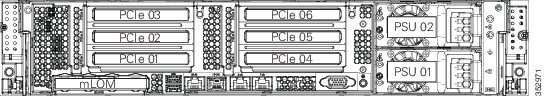
a.![]() Align the GPU card with the socket on the riser, and then gently push the card’s edge connector into the socket. Press evenly on both corners of the card to avoid damaging the connector.
Align the GPU card with the socket on the riser, and then gently push the card’s edge connector into the socket. Press evenly on both corners of the card to avoid damaging the connector.
b.![]() Connect the GPU card power cable (UCSC-GPUCBL-240M4) into the GPU card and into the GPU POWER connector on the PCIe riser (see Figure D-1).
Connect the GPU card power cable (UCSC-GPUCBL-240M4) into the GPU card and into the GPU POWER connector on the PCIe riser (see Figure D-1).
c.![]() Return the securing plate to the riser. Insert the two hinge-tabs into the two slots on the riser, and then swing the securing plate closed.
Return the securing plate to the riser. Insert the two hinge-tabs into the two slots on the riser, and then swing the securing plate closed.
d.![]() Tighten the single thumbscrew that holds the securing plate.
Tighten the single thumbscrew that holds the securing plate.
e.![]() Close the card-tab retainer (see Figure D-1).
Close the card-tab retainer (see Figure D-1).
f.![]() Position the PCIe riser over its socket on the motherboard and over its alignment features in the chassis.
Position the PCIe riser over its socket on the motherboard and over its alignment features in the chassis.
g.![]() Carefully push down on both ends of the PCIe riser to fully engage its circuit board connector with the socket on the motherboard.
Carefully push down on both ends of the PCIe riser to fully engage its circuit board connector with the socket on the motherboard.
Step 7![]() Replace the server in the rack, replace cables, and then power on the server by pressing the Power button.
Replace the server in the rack, replace cables, and then power on the server by pressing the Power button.
Step 8![]() Continue with Installing Drivers to Support the GPU Cards.
Continue with Installing Drivers to Support the GPU Cards.
Note![]() If you installed an NVIDIA Tesla M10 GPU, you must install GRID licenses to use the GRID features. See Using NVIDIA GRID License Server For M-Series GPUs.
If you installed an NVIDIA Tesla M10 GPU, you must install GRID licenses to use the GRID features. See Using NVIDIA GRID License Server For M-Series GPUs.
Installing a High-Power GPU Card and Server Conversion Kit
Use this section to install or replace a GPU card that draws 250 W or more power. A server conversion kit is required to ensure adequate airflow and cooling. Use this section to install the following GPUs:
High-Power GPU Server Conversion Kit
The contents of the conversion kit are as follows:
- Replacement fan-module fan cage
- CPU cleaning kit
- Low-profile CPU heatsinks (two)
- Replacement air baffle (includes base, bridge, and filler panel)
- High-power GPU card straight power cable (UCS-300WKIT-240M4)
Note![]() Your GPU card might be shipped with two power cables: a straight cable and a Y-cable. The straight cable is used for connecting power to the GPU card in this C240 M4 server; do not use the Y-cable, which is used for connecting the GPU card in external devices only (such as the Magma chassis).
Your GPU card might be shipped with two power cables: a straight cable and a Y-cable. The straight cable is used for connecting power to the GPU card in this C240 M4 server; do not use the Y-cable, which is used for connecting the GPU card in external devices only (such as the Magma chassis).
Note![]() The GPU card comes with a front support bracket factory-installed, which is required for installation into this C240 M4 server. This bracket is not compatible for installation in an external storage device such as the Magma chassis. In that case, remove the bracket by removing its three thumbscrews.
The GPU card comes with a front support bracket factory-installed, which is required for installation into this C240 M4 server. This bracket is not compatible for installation in an external storage device such as the Magma chassis. In that case, remove the bracket by removing its three thumbscrews.
Double-Wide GPU Power Cables
In the table below, the cable that is used with the GPU is listed. It is also indicated whether the cable is included in the GPU BOM or must be ordered separately.
Separate = Cable must be ordered separately when the ordering tool prompts you.
Included = Cable is included with the GPU; no additional action is needed.
|
|
|
|
|
|---|---|---|---|
Installing the NVIDIA K80 GPU Card
Step 1![]() Shut down and power off the server as described in Shutting Down and Powering Off the Server.
Shut down and power off the server as described in Shutting Down and Powering Off the Server.
Step 2![]() Slide the server out the front of the rack far enough so that you can remove the top cover. You might have to detach cables from the rear panel to provide clearance.
Slide the server out the front of the rack far enough so that you can remove the top cover. You might have to detach cables from the rear panel to provide clearance.
Step 3![]() Remove the top cover as described in Removing and Replacing the Server Top Cover.
Remove the top cover as described in Removing and Replacing the Server Top Cover.
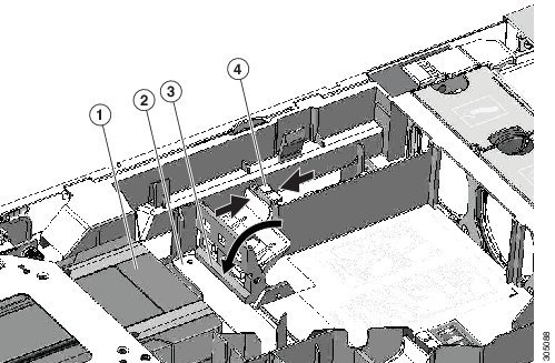
Step 4![]() If the server has a SuperCap power module (RAID battery unit) in the holder on the air baffle, disconnect the cable from the module and then remove it from the clips on the air baffle and set it aside (Figure D-3).
If the server has a SuperCap power module (RAID battery unit) in the holder on the air baffle, disconnect the cable from the module and then remove it from the clips on the air baffle and set it aside (Figure D-3).
Step 5![]() Remove the plastic air-baffle that covers the CPUs and DIMMs.
Remove the plastic air-baffle that covers the CPUs and DIMMs.
Step 6![]() Remove the existing server fan cage (see Figure D-3):
Remove the existing server fan cage (see Figure D-3):
a.![]() Open the plastic locking-lever at each end of the existing fan cage to the upright 90-degree position.
Open the plastic locking-lever at each end of the existing fan cage to the upright 90-degree position.
b.![]() Lift the existing fan cage with fan modules from the server. Set the fan cage with fan modules aside.
Lift the existing fan cage with fan modules from the server. Set the fan cage with fan modules aside.
Step 7![]() Install the new empty server fan cage from the conversion kit:
Install the new empty server fan cage from the conversion kit:
a.![]() Open the plastic locking-lever at each end of the new fan cage to the upright 90-degree position.
Open the plastic locking-lever at each end of the new fan cage to the upright 90-degree position.
b.![]() Set the new fan cage into the guides on the chassis walls and then lower the cage evenly.
Set the new fan cage into the guides on the chassis walls and then lower the cage evenly.
c.![]() Close the plastic locking-lever at each end of the fan cage to the flat, locked position.
Close the plastic locking-lever at each end of the fan cage to the flat, locked position.
Step 8![]() Move the six fan modules from the old fan cage to the new fan cage that you just installed:
Move the six fan modules from the old fan cage to the new fan cage that you just installed:
a.![]() Pinch the two finger latches on each fan module together, then lift up on the module to remove it from the cage (see Figure D-3).
Pinch the two finger latches on each fan module together, then lift up on the module to remove it from the cage (see Figure D-3).
b.![]() Set the fan module in an open slot in the new fan cage, aligning the connector on the bottom of the fan module with the connector on the motherboard.
Set the fan module in an open slot in the new fan cage, aligning the connector on the bottom of the fan module with the connector on the motherboard.
Note![]() The arrow label on the top of the fan module, which indicates the direction of airflow, should point toward the rear of the server.
The arrow label on the top of the fan module, which indicates the direction of airflow, should point toward the rear of the server.
c.![]() Press down gently on the fan module until the latch clicks and locks in place.
Press down gently on the fan module until the latch clicks and locks in place.
d.![]() Repeat until you have moved all fan modules into the new fan cage.
Repeat until you have moved all fan modules into the new fan cage.
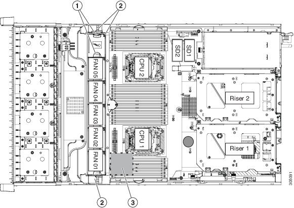
Figure D-3 Fan Cage and Fan Modules
|
|
|
SuperCap power module position on removable air baffle (air baffle not shown) |
|
|
|
|
Step 9![]() Remove the existing heatsink from each CPU.
Remove the existing heatsink from each CPU.
a.![]() Use a Number 2 Phillips-head screwdriver to loosen the four captive screws that secure the heatsink.
Use a Number 2 Phillips-head screwdriver to loosen the four captive screws that secure the heatsink.
Note![]() Alternate loosening each screw evenly to avoid damaging the heatsink or CPU.
Alternate loosening each screw evenly to avoid damaging the heatsink or CPU.
b.![]() Lift the heatsink off of the CPU and set it aside.
Lift the heatsink off of the CPU and set it aside.
Step 10![]() Use the heatsink cleaning kit that comes with the conversion kit to clean the existing thermal grease from the top surface of each CPU.
Use the heatsink cleaning kit that comes with the conversion kit to clean the existing thermal grease from the top surface of each CPU.
Step 11![]() Install the low-profile replacement heatsinks that come with the conversion kit:
Install the low-profile replacement heatsinks that come with the conversion kit:
a.![]() Remove the protective tape from the pre-applied pad of thermal grease that is on the underside of the new heatsink.
Remove the protective tape from the pre-applied pad of thermal grease that is on the underside of the new heatsink.
b.![]() Align the four heatsink captive screws with the motherboard standoffs, and then use a Number 2 Phillips-head screwdriver to tighten the captive screws evenly.
Align the four heatsink captive screws with the motherboard standoffs, and then use a Number 2 Phillips-head screwdriver to tighten the captive screws evenly.
Note![]() Alternate tightening each screw evenly to avoid damaging the heatsink or CPU.
Alternate tightening each screw evenly to avoid damaging the heatsink or CPU.
Step 12![]() Set the base of the replacement air baffle into the server (see Figure D-4).
Set the base of the replacement air baffle into the server (see Figure D-4).
|
|
|
||
|
|
|
||
|
|
|
Step 13![]() Remove the PCIe riser from the server.
Remove the PCIe riser from the server.
Note![]() If you have only a single high-power GPU, it must be installed in PCIe riser 1A, slot 2.
If you have only a single high-power GPU, it must be installed in PCIe riser 1A, slot 2.
a.![]() Grasp the top of the riser and lift straight up on both ends to disengage its circuit board from the socket on the motherboard.
Grasp the top of the riser and lift straight up on both ends to disengage its circuit board from the socket on the motherboard.
b.![]() Set the riser on an antistatic surface.
Set the riser on an antistatic surface.
c.![]() On the bottom of the riser, loosen the single thumbscrew that holds the securing plate (see Figure D-5).
On the bottom of the riser, loosen the single thumbscrew that holds the securing plate (see Figure D-5).
d.![]() Swing open the securing plate and remove it from the riser to provide access.
Swing open the securing plate and remove it from the riser to provide access.
e.![]() Swing open the card-tab retainer (see Figure D-5).
Swing open the card-tab retainer (see Figure D-5).
Figure D-5 PCIe Riser Securing Features (Three-Slot Riser Shown)
|
|
|
||
|
|
Securing plate thumbscrew (knob not visible on underside of plate) |
|
Step 14![]() Install your first GPU card into PCIe riser 1A, slot 2. See Figure D-6 for the riser and slot locations.
Install your first GPU card into PCIe riser 1A, slot 2. See Figure D-6 for the riser and slot locations.
Note![]() Observe the populations rules in GPU Card Configuration Rules. Use riser 1 version 1A (UCSC-PCI-1A-240M4), slot 2 or riser 2 (slot 5) for GPU cards. GPU cards are not supported in PCIe riser 1 version 1B (UCSC-PCI-1B-240M4) or 1C (UCSC-PCI-1C-240M4).
Observe the populations rules in GPU Card Configuration Rules. Use riser 1 version 1A (UCSC-PCI-1A-240M4), slot 2 or riser 2 (slot 5) for GPU cards. GPU cards are not supported in PCIe riser 1 version 1B (UCSC-PCI-1B-240M4) or 1C (UCSC-PCI-1C-240M4).
Figure D-6 Rear Panel, Showing PCIe Slots
a.![]() Align the GPU card with the socket on the riser, and then gently push the card’s edge connector into the socket. Press evenly on both corners of the card to avoid damaging the connector.
Align the GPU card with the socket on the riser, and then gently push the card’s edge connector into the socket. Press evenly on both corners of the card to avoid damaging the connector.
b.![]() The straight-cable connectors are color-coded. Connect the GPU card power cable black connector into black connector on the GPU card and the white connector into the white GPU POWER connector on the PCIe riser (see Figure D-5).
The straight-cable connectors are color-coded. Connect the GPU card power cable black connector into black connector on the GPU card and the white connector into the white GPU POWER connector on the PCIe riser (see Figure D-5).
For a list of cables that go with supported double-wide GPUs, see Double-Wide GPU Power Cables.
Note![]() Your GPU card might be shipped with two power cables: a straight cable and a Y-cable. The straight cable is used for connecting power to the GPU card in this server; do not use the Y-cable, which is used for connecting the GPU card in external devices only.
Your GPU card might be shipped with two power cables: a straight cable and a Y-cable. The straight cable is used for connecting power to the GPU card in this server; do not use the Y-cable, which is used for connecting the GPU card in external devices only.
c.![]() Close the card-tab retainer (see Figure D-5).
Close the card-tab retainer (see Figure D-5).
d.![]() Return the securing plate to the riser. Insert the two hinge-tabs into the two slots on the riser, and then swing the securing plate closed.
Return the securing plate to the riser. Insert the two hinge-tabs into the two slots on the riser, and then swing the securing plate closed.
e.![]() Tighten the single thumbscrew that holds the securing plate.
Tighten the single thumbscrew that holds the securing plate.
Step 15![]() Install the PCIe riser with GPU card back into the server:
Install the PCIe riser with GPU card back into the server:
a.![]() Position the PCIe riser over its socket on the motherboard and over its alignment features in the chassis.
Position the PCIe riser over its socket on the motherboard and over its alignment features in the chassis.
b.![]() Carefully push down on both ends of the PCIe riser to fully engage its circuit board connector with the socket on the motherboard.
Carefully push down on both ends of the PCIe riser to fully engage its circuit board connector with the socket on the motherboard.
Step 16![]() Insert the front support bracket into the latch that is on the air baffle base that you installed in Step 12.
Insert the front support bracket into the latch that is on the air baffle base that you installed in Step 12.
a.![]() Pinch the latch release tab (see Figure D-7) and hinge the latch toward the front of the server.
Pinch the latch release tab (see Figure D-7) and hinge the latch toward the front of the server.
b.![]() Hinge the latch back down so that its lip closes over the front edge of the support bracket that is attached to the GPU card (see Figure D-7).
Hinge the latch back down so that its lip closes over the front edge of the support bracket that is attached to the GPU card (see Figure D-7).
c.![]() Ensure that the latch release tab clicks and locks the latch in place.
Ensure that the latch release tab clicks and locks the latch in place.
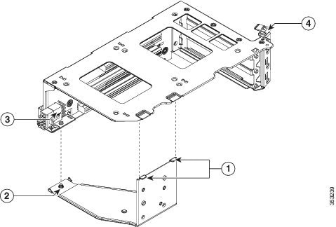
Figure D-7 GPU Front Support Bracket Inserted to Air Baffle Latch
|
|
|
||
|
|
|
Note![]() If your server has two GPUs, skip the following step. The filler panel shunts airflow to the PCIe riser in which a GPU is installed. A system with two GPUs does not use the filler.
If your server has two GPUs, skip the following step. The filler panel shunts airflow to the PCIe riser in which a GPU is installed. A system with two GPUs does not use the filler.
Step 17![]() If your system has only a single high-power GPU, install the filler panel to the air baffle base in slot 2 as shown in Figure D-8. Slide the filler panel edges into the slots as shown.
If your system has only a single high-power GPU, install the filler panel to the air baffle base in slot 2 as shown in Figure D-8. Slide the filler panel edges into the slots as shown.
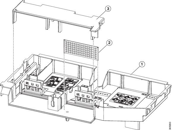
Figure D-8 Air Baffle Filler Panel and Bridge
|
|
|
||
|
|
|
Path for SuperCap module cable through air baffle opening (SuperCap module not shown) |
|
|
|
|
Step 18![]() Install the bridge to the air baffle. Ridges on the bridge legs slide into slots on the air baffle base (see Figure D-8).
Install the bridge to the air baffle. Ridges on the bridge legs slide into slots on the air baffle base (see Figure D-8).
Step 19![]() If the server has a SuperCap power module (RAID battery unit), install it to the holding clip on the new air baffle (see Figure D-8).
If the server has a SuperCap power module (RAID battery unit), install it to the holding clip on the new air baffle (see Figure D-8).
a.![]() Set the module into the clips and gently press down until the clip closes over the module.
Set the module into the clips and gently press down until the clip closes over the module.
b.![]() Route the module’s cable through the opening in the air baffle (see Figure D-8) so that it does not interfere with the server top cover.
Route the module’s cable through the opening in the air baffle (see Figure D-8) so that it does not interfere with the server top cover.
Step 20![]() Replace the top cover to the server.
Replace the top cover to the server.
Step 21![]() Replace the server in the rack, replace cables, and then power on the server by pressing the Power button.
Replace the server in the rack, replace cables, and then power on the server by pressing the Power button.
Step 22![]() Continue with Installing Drivers to Support the GPU Cards.
Continue with Installing Drivers to Support the GPU Cards.
Note![]() If you installed an NVIDIA Tesla M-series GPU, you must install GRID licenses to use the GRID features. See Using NVIDIA GRID License Server For M-Series GPUs.
If you installed an NVIDIA Tesla M-series GPU, you must install GRID licenses to use the GRID features. See Using NVIDIA GRID License Server For M-Series GPUs.
Using NVIDIA GRID License Server For M-Series GPUs
This section applies to the following GPUs:
Use the topics in this section in the following order when obtaining and using NVIDIA GRID licenses.
1.![]() Familiarize yourself with the NVIDIA GRID License Server.
Familiarize yourself with the NVIDIA GRID License Server.
2.![]() Register your product activation keys with NVIDIA.
Register your product activation keys with NVIDIA.
3.![]() Download the GRID software suite.
Download the GRID software suite.
4.![]() Install the GRID License Server software to a host.
Install the GRID License Server software to a host.
5.![]() Generate licenses on the NVIDIA Licensing Portal and download them.
Generate licenses on the NVIDIA Licensing Portal and download them.
7.![]() Decide whether to use the GPU in compute mode or graphics mode.
Decide whether to use the GPU in compute mode or graphics mode.
NVIDIA GRID License Server Overview
The NVIDIA M-Series GPUs combine Tesla and GRID functionality when the licensed GRID features such as GRID vGPU and GRID Virtual Workstation are enabled. These features are enabled during OS boot by borrowing a software license that is served over the network from the NVIDIA GRID License Server virtual appliance. The license is returned to the license server when the OS shuts down.
You obtain the licenses that are served by the GRID License Server from NVIDIA’s Licensing Portal as downloadable license files, which you install into the GRID License Server via its management interface (see Figure D-9).
Figure D-9 GRID Licensing Architecture
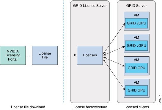
There are three editions of GRID licenses, which enable three different classes of GRID features. The GRID software automatically selects the license edition based on the features that you are using (see Table D-4 ).
|
|
|
|---|---|
Registering Your Product Activation Keys With NVIDIA
After your order is processed, NVIDIA sends you a Welcome email that contains your product activation keys (PAKs) and a list of the types and quantities of licenses that you purchased.
Step 1![]() Select the Log In link, or the Register link if you do not already have an account.
Select the Log In link, or the Register link if you do not already have an account.
The NVIDIA Software Licensing Center > License Key Registration dialog opens.
Step 2![]() Complete the License Key Registration form and then click Submit My Registration Information.
Complete the License Key Registration form and then click Submit My Registration Information.
The NVIDIA Software Licensing Center > Product Information Software dialog opens.
Step 3![]() If you have additional PAKs, click Register Additional Keys. For each additional key, complete the form on the License Key Registration dialog and then click Submit My Registration Information.
If you have additional PAKs, click Register Additional Keys. For each additional key, complete the form on the License Key Registration dialog and then click Submit My Registration Information.
Step 4![]() Agree to the terms and conditions and set a password when prompted.
Agree to the terms and conditions and set a password when prompted.
Downloading the GRID Software Suite
Step 1![]() Return to the NVIDIA Software Licensing Center > Product Information Software dialog.
Return to the NVIDIA Software Licensing Center > Product Information Software dialog.
Step 2![]() Click the Current Releases tab.
Click the Current Releases tab.
Step 3![]() Click the NVIDIA GRID link to access the Product Download dialog. This dialog includes download links for:
Click the NVIDIA GRID link to access the Product Download dialog. This dialog includes download links for:
–![]() NVIDIA License Manager software
NVIDIA License Manager software
Step 4![]() Use the links to download the software.
Use the links to download the software.
Installing NVIDIA GRID License Server Software
For full installation instructions and troubleshooting, refer to the NVIDIA GRID License Server User Guide. Also refer to the NVIDIA GRID License Server Release Notes for the latest information about your release.
Platform Requirements for NVIDIA GRID License Server
- The hosting platform can be a physical or a virtual machine. NVIDIA recommends using a host that is dedicated only to running the License Server.
- The hosting platform must run a supported Windows OS.
- The hosting platform must have a constant IP address.
- The hosting platform must have at least one constant Ethernet MAC address.
- The hosting platform’s date and time must be set accurately.
Installing on Windows
The License Server requires a Java runtime environment and an Apache Tomcat installation. Apache Tomcat is installed when you use the NVIDIA installation wizard for Windows.
Step 1![]() Download and install the latest Java 32-bit runtime environment from https://www.oracle.com/downloads/index.html.
Download and install the latest Java 32-bit runtime environment from https://www.oracle.com/downloads/index.html.
Note![]() Install the 32-bit Java Runtime Environment, regardless of whether your platform is Windows 32-bit or 64-bit.
Install the 32-bit Java Runtime Environment, regardless of whether your platform is Windows 32-bit or 64-bit.
Step 2![]() Create a server interface:
Create a server interface:
a.![]() On the NVIDIA Software Licensing Center dialog, click Grid Licensing > Create License Server.
On the NVIDIA Software Licensing Center dialog, click Grid Licensing > Create License Server.
b.![]() On the Create Server dialog, fill in your desired server details.
On the Create Server dialog, fill in your desired server details.
c.![]() Save the.bin file that is generated onto your license server for installation.
Save the.bin file that is generated onto your license server for installation.
Step 3![]() Unzip the NVIDIA License Server installer Zip file that you downloaded previously and run
Unzip the NVIDIA License Server installer Zip file that you downloaded previously and run setup.exe.
Step 4![]() Accept the EULA for the NVIDIA License Server software and the Apache Tomcat software. Tomcat is installed automatically during the License Server installation.
Accept the EULA for the NVIDIA License Server software and the Apache Tomcat software. Tomcat is installed automatically during the License Server installation.
Step 5![]() Use the installer wizard to step through the installation.
Use the installer wizard to step through the installation.
Note![]() On the Choose Firewall Options dialog, select the ports to be opened in the firewall. NVIDIA recommends that you use the default setting, which opens port 7070 but leaves port 8080 closed.
On the Choose Firewall Options dialog, select the ports to be opened in the firewall. NVIDIA recommends that you use the default setting, which opens port 7070 but leaves port 8080 closed.
Step 6![]() Verify the installation. Open a web browser on the License Server host and connect to the URL http://localhost:8080/licserver. If the installation was successful, you see the NVIDIA License Client Manager interface.
Verify the installation. Open a web browser on the License Server host and connect to the URL http://localhost:8080/licserver. If the installation was successful, you see the NVIDIA License Client Manager interface.
Installing on Linux
The License Server requires a Java runtime environment and an Apache Tomcat installation. You must install both separately before installing the License Server on Linux.
Step 1![]() Verify that Java was installed with your Linux installation. Use the following command:
Verify that Java was installed with your Linux installation. Use the following command:
If no Java version is displayed, use your Linux package manager to install with the following command:
Step 2![]() Use your Linux package manager to install the tomcat and tomcat-webapps packages.
Use your Linux package manager to install the tomcat and tomcat-webapps packages.
a.![]() Use the following command to install Tomcat:
Use the following command to install Tomcat:
b.![]() Enable the Tomcat service for automatic startup on boot:
Enable the Tomcat service for automatic startup on boot:
d.![]() Verify that the Tomcat service is operational. Open a web browser on the License Server host and connect to the URL http://localhost:8080. If the installation was successful, you see the Tomcat webapp.
Verify that the Tomcat service is operational. Open a web browser on the License Server host and connect to the URL http://localhost:8080. If the installation was successful, you see the Tomcat webapp.
Step 3![]() Install the License Server:
Install the License Server:
a.![]() Unpack the License Server tar file using the following command:
Unpack the License Server tar file using the following command:
b.![]() Run the unpacked setup binary as root:
Run the unpacked setup binary as root:
c.![]() Accept the EULA and then continue with the installation wizard to finish the installation.
Accept the EULA and then continue with the installation wizard to finish the installation.
Note![]() On the Choose Firewall Options dialog, select the ports to be opened in the firewall. NVIDIA recommends that you use the default setting, which opens port 7070 but leaves port 8080 closed.
On the Choose Firewall Options dialog, select the ports to be opened in the firewall. NVIDIA recommends that you use the default setting, which opens port 7070 but leaves port 8080 closed.
Step 4![]() Verify the installation. Open a web browser on the License Server host and connect to the URL http://localhost:8080/licserver. If the installation was successful, you see the NVIDIA License Client Manager interface.
Verify the installation. Open a web browser on the License Server host and connect to the URL http://localhost:8080/licserver. If the installation was successful, you see the NVIDIA License Client Manager interface.
Installing GRID Licenses From the NVIDIA Licensing Portal to the License Server
Accessing the GRID License Server Management Interface
Open a web browser on the License Server host and access the URL http://localhost:8080/licserver
If you configured the License Server host’s firewall to permit remote access to the License Server, the management interface is accessible from remote machines at the URL http://hostname:8080/licserver
Reading Your License Server’s MAC Address
Your License Server’s Ethernet MAC address is used as an identifier when registering the License Server with NVIDIA’s Licensing Portal.
Step 1![]() Access the GRID License Server Management Interface in a browser. See Accessing the GRID License Server Management Interface.
Access the GRID License Server Management Interface in a browser. See Accessing the GRID License Server Management Interface.
Step 2![]() In the left-side License Server panel, select Configuration. The License Server Configuration panel opens. Next to Server host ID, a pull-down menu lists the possible Ethernet MAC addresses.
In the left-side License Server panel, select Configuration. The License Server Configuration panel opens. Next to Server host ID, a pull-down menu lists the possible Ethernet MAC addresses.
Step 3![]() Select your License Server’s MAC address from the Server host ID pull-down.
Select your License Server’s MAC address from the Server host ID pull-down.
Note![]() It is important to use the same Ethernet ID consistently to identify the server when generating licenses on NVIDIA’s Licensing Portal. NVIDIA recommends that you select one entry for a primary, non-removable Ethernet interface on the platform.
It is important to use the same Ethernet ID consistently to identify the server when generating licenses on NVIDIA’s Licensing Portal. NVIDIA recommends that you select one entry for a primary, non-removable Ethernet interface on the platform.
Installing Licenses From the Licensing Portal
Step 1![]() Access the GRID License Server Management Interface in a browser. See Accessing the GRID License Server Management Interface.
Access the GRID License Server Management Interface in a browser. See Accessing the GRID License Server Management Interface.
Step 2![]() In the left-side License Server panel, select Configuration. The License Server Configuration panel opens.
In the left-side License Server panel, select Configuration. The License Server Configuration panel opens.
Step 3![]() Use the License Server Configuration menu to install the.bin file that you generated earlier.
Use the License Server Configuration menu to install the.bin file that you generated earlier.
b.![]() Browse to the license.bin file that you want to install and click Open.
Browse to the license.bin file that you want to install and click Open.
The license file is installed on your License Server. When installation is complete, you see the confirmation message, “Successfully applied license file to license server.”
Viewing Available Licenses
Use the following procedure to view which licenses are installed and available, along with their properties.
Step 1![]() Access the GRID License Server Management Interface in a browser. See Accessing the GRID License Server Management Interface.
Access the GRID License Server Management Interface in a browser. See Accessing the GRID License Server Management Interface.
Step 2![]() In the left-side License Server panel, select Licensed Feature Usage.
In the left-side License Server panel, select Licensed Feature Usage.
Step 3![]() Click on a feature in the Feature column to see detailed information about the current usage of that feature.
Click on a feature in the Feature column to see detailed information about the current usage of that feature.
Viewing Current License Usage
Use the following procedure to view information about which licenses are currently in-use and borrowed from the server.
Step 1![]() Access the GRID License Server Management Interface in a browser. See Accessing the GRID License Server Management Interface.
Access the GRID License Server Management Interface in a browser. See Accessing the GRID License Server Management Interface.
Step 2![]() In the left-side License Server panel, select Licensed Clients.
In the left-side License Server panel, select Licensed Clients.
Step 3![]() To view detailed information about a single licensed client, click on its Client ID in the list.
To view detailed information about a single licensed client, click on its Client ID in the list.
Managing GRID Licenses
Features that require GRID licensing run at reduced capability until a GRID license is acquired.
Acquiring a GRID License on Windows
To acquire a GRID license on Windows, use the following procedure.
Step 1![]() Open the NVIDIA Control Panel using one of the following methods:
Open the NVIDIA Control Panel using one of the following methods:
- Right-click on the Windows desktop and select NVIDIA Control Panel from the menu.
- Open Windows Control Panel and double-click the NVIDIA Control Panel icon.
Step 2![]() In the NVIDIA Control Panel left-pane under Licensing, select Manage License.
In the NVIDIA Control Panel left-pane under Licensing, select Manage License.
The Manage License task pane opens and shows the current license edition being used. The GRID software automatically selects the license edition based on the features that you are using. The default is Tesla (unlicensed).
Step 3![]() If you want to acquire a license for GRID Virtual Workstation, under License Edition, select GRID Virtual Workstation.
If you want to acquire a license for GRID Virtual Workstation, under License Edition, select GRID Virtual Workstation.
Step 4![]() In the License Server field, enter the address of your local GRID License Server.
In the License Server field, enter the address of your local GRID License Server.
The address can be a domain name or an IP address.
Step 5![]() In the Port Number field, enter your port number of leave it set to the default used by the server, which is 7070.
In the Port Number field, enter your port number of leave it set to the default used by the server, which is 7070.
The system requests the appropriate license edition from your configured License Server. After a license is successfully acquired, the features of that license edition are enabled.
Note![]() After you configure licensing settings in the NVIDIA Control Panel, the settings persist across reboots.
After you configure licensing settings in the NVIDIA Control Panel, the settings persist across reboots.
Acquiring a GRID License on Linux
To acquire a GRID license on Linux, use the following procedure.
Step 1![]() Edit the configuration file /etc/nvidia/gridd.conf:
Edit the configuration file /etc/nvidia/gridd.conf:
Step 2![]() Edit the
Edit the ServerUrl line with the address of your local GRID License Server.
The address can be a domain name or an IP address. See the example file below.
Step 3![]() Append the port number (default 7070) to the end of the address with a colon. See the example file below.
Append the port number (default 7070) to the end of the address with a colon. See the example file below.
Step 4![]() Edit the
Edit the FeatureType line with the integer for the license type. See the example file below.
Step 5![]() Restart the nvidia-gridd service.
Restart the nvidia-gridd service.
The service automatically acquires the license edition that you specified in the FeatureType line. You can confirm this in /var/log/messages.
Note![]() After you configure licensing settings in gridd.conf, the settings persist across reboots.
After you configure licensing settings in gridd.conf, the settings persist across reboots.
Switching Between Compute Mode and Graphics Mode
Overview of GPU Modes
The NVIDIA Tesla M60 GPU is shipped in compute mode, which is optimized for high-performance compute (HPC) applications. However, while compute mode is best for HPC usage, it can cause compatibility issues with OS and hypervisors if you use the GPU primarily as a graphics device.
The mode is determined at power-on, from settings stored in the GPU’s non-volatile memory. You can use the command-line tool gpumodeswitch to toggle the GPU between compute mode and graphics mode. Table D-5 and Table D-6 compare the compute mode and graphic mode default settings.
Using gpumodeswitch
The command line utility gpumodeswitch can be run in the following environments:
- Windows 64-bit command prompt (requires administrator permissions)
- Linux 32/64-bit shell (including Citrix XenServer dom0) (requires root permissions)
Note![]() Consult NVIDIA product release notes for the latest information on compatibility with compute and graphic modes.
Consult NVIDIA product release notes for the latest information on compatibility with compute and graphic modes.
The gpumodeswitch utility supports the following commands:
This command writes information to a log file named listgpumodes.txt in the current working directory.
Switches to graphics mode. Switches mode of all supported GPUs in the server unless you specify otherwise when prompted.
Switches to compute mode. Switches mode of all supported GPUs in the server unless you specify otherwise when prompted.
Note![]() After you switch GPU mode, reboot the server to ensure that the modified resources of the GPU are correctly accounted for by any OS or hypervisor running on the server.
After you switch GPU mode, reboot the server to ensure that the modified resources of the GPU are correctly accounted for by any OS or hypervisor running on the server.
Installing Drivers to Support the GPU Cards
After you install the hardware, you must update to the correct level of server BIOS and then install GPU drivers and other software in this order:
1. Updating the C240 M4 Server BIOS
Install the latest Cisco UCS C240 M4 server BIOS by using the Host Upgrade Utility for the Cisco UCS C240 M4 server.
Note![]() You must do this procedure before you update the NVIDIA drivers.
You must do this procedure before you update the NVIDIA drivers.
Step 1![]() Navigate to the following URL: http://www.cisco.com/cisco/software/navigator.html.
Navigate to the following URL: http://www.cisco.com/cisco/software/navigator.html.
Step 2![]() Click Servers–Unified Computing in the middle column.
Click Servers–Unified Computing in the middle column.
Step 3![]() Click Cisco UCS C-Series Rack-Mount Standalone Server Software in the right-hand column.
Click Cisco UCS C-Series Rack-Mount Standalone Server Software in the right-hand column.
Step 4![]() Click the name of your model of server in the right-hand column.
Click the name of your model of server in the right-hand column.
Step 5![]() Click Unified Computing System (UCS) Server Firmware.
Click Unified Computing System (UCS) Server Firmware.
Step 6![]() Click the release number.
Click the release number.
Step 7![]() Click Download Now to download the ucs-server platform-huu-version_number.iso file.
Click Download Now to download the ucs-server platform-huu-version_number.iso file.
Step 8![]() Verify the information on the next page, and then click Proceed With Download.
Verify the information on the next page, and then click Proceed With Download.
Step 9![]() Continue through the subsequent screens to accept the license agreement and browse to a location where you want to save the file.
Continue through the subsequent screens to accept the license agreement and browse to a location where you want to save the file.
Step 10![]() Use the Host Upgrade Utility to update the server BIOS.
Use the Host Upgrade Utility to update the server BIOS.
The user guides for the Host Upgrade Utility are at Utility User Guides.
2. Updating the GPU Drivers
After you update the server BIOS, you can install GPU drivers to your hypervisor virtual machine.
Step 1![]() Install your hypervisor software on a computer. Refer to your hypervisor documentation for the installation instructions.
Install your hypervisor software on a computer. Refer to your hypervisor documentation for the installation instructions.
Step 2![]() Create a virtual machine in your hypervisor. Refer to your hypervisor documentation for instructions.
Create a virtual machine in your hypervisor. Refer to your hypervisor documentation for instructions.
Step 3![]() Install the GPU drivers to the virtual machine. Download the drivers from either:
Install the GPU drivers to the virtual machine. Download the drivers from either:
- NVIDIA Enterprise Portal for GRID hypervisor downloads (requires NVIDIA login): https://nvidia.flexnetoperations.com/
- NVIDIA public driver area: http://www.nvidia.com/Download/index.aspx
- AMD: http://support.amd.com/en-us/download
Step 5![]() Check that the virtual machine is able to recognize the GPU card. In Windows, use the Device Manager and look under Display Adapters.
Check that the virtual machine is able to recognize the GPU card. In Windows, use the Device Manager and look under Display Adapters.
 Feedback