Overview
This chapter provides an overview of the Cisco UCS C240 M4 server features:
External Features Overview
The figures in this chapter show an overview of external server features.
The server is orderable in four different versions, each with one of four different front panel/drive backplane configurations:
- Cisco UCS C240 M4—Small form-factor (SFF) drives with 24-drive backplane and expander.
This version holds up to 24 2.5-inch SAS/SATA hard drives or solid state drives (SSDs). This version also supports up to 2 NVMe PCIe SSDs. See Figure 1-1. - Cisco UCS C240 M4—SFF drives, with 16-drive backplane and integrated expander.
This version holds up to 16 2.5-inch SAS/SATA hard drives or solid state drives. This version also supports up to 2 NVMe PCIe SSDs. See Figure 1-2. - Cisco UCS C240 M4—SFF drives, with 8-drive direct-connect backplane and no expander.
This version holds up to 8 2.5-inch SAS/SATA hard drives or solid state drives. This version also supports up to 2 NVMe PCIe SSDs. See Figure 1-3. - Cisco UCS C240 M4—Large form-factor (LFF) drives, with 12-drive backplane and integrated expander. This version holds up to 12 3.5-inch SAS/SATA hard drives. See Figure 1-4.
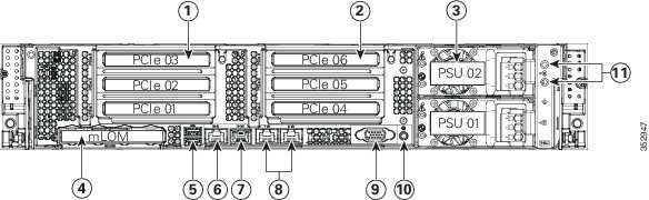
- The rear panel features are the same for all four versions of the server. See Figure 1-5.
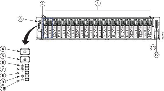
Figure 1-1 shows the front panel features of the SFF drives, 24-drive version of the server. This version of the server has a 24-drive backplane and an integrated expander.
Figure 1-1 Cisco UCS C240 M4 Server (SFF Drives, 24-Drive) Front Panel Features
|
|
|
||
|
|
Drive bays 1 and 2 support NVMe PCIe SSDs and SAS/SATA drives. |
|
|
|
|
|
||
|
|
|
||
|
|
|
||
|
|
|
KVM connector |
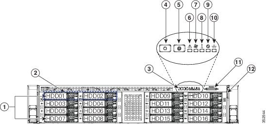
Figure 1-2 shows the front-panel features of the SFF drives, 16-drive version of the server. This version of the server has a 16-drive backplane and an integrated expander.
Figure 1-2 Cisco UCS C240 M4 Server (SFF Drives, 16-Drive) Front Panel Features
|
|
|
||
|
|
Drive bays 1 and 2 support NVMe PCIe SSDs and SAS/SATA drives. |
|
|
|
|
|
||
|
|
|
||
|
|
|
KVM connector |
|
|
|
|
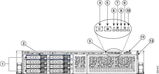
Figure 1-3 shows the front-panel features of the SFF drives, 8-drive version of the server. This version of the server has a direct-connect, 8-drive backplane (no expander).
Figure 1-3 Cisco UCS C240 M4 Server (SFF Drives, 8-Drive) Front Panel Features
|
|
|
||
|
|
Drive bays 1 and 2 support NVMe PCIe SSDs and SAS/SATA drives. |
|
|
|
|
|
||
|
|
|
||
|
|
|
KVM connector |
|
|
|
|
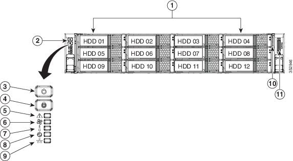
Figure 1-4 shows the front panel features of the LFF drives, 12-drive version of the server. This version of the server has a 12-drive backplane with an integrated expander.
Figure 1-4 Cisco UCS C240 M4 Server (LFF Drives, 12-Drive) Front Panel Features
|
|
|
||
|
|
|
||
|
|
|
||
|
|
|
||
|
|
|
KVM connector |
|
|
|
|
Figure 1-5 shows the rear panel features of the server (identical for all versions of the server).
Figure 1-5 Cisco UCS C240 M4 Server Rear Panel Features
|
|
*Slot 3 not present in all versions. See Replacing a PCIe Card for riser options and slot specifications. |
|
|
|
|
|
||
|
|
Power supplies (DC power supplies shown) See Power Specifications for specifications and options. |
|
|
|
|
|
||
|
|
|
||
|
|
|
Replaceable Component Locations
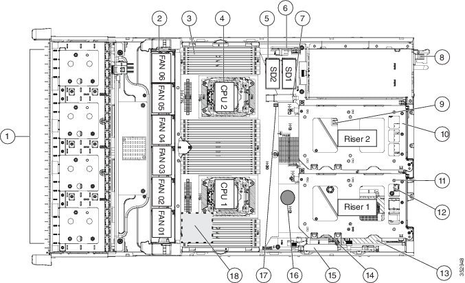
Figure 1-6 shows the locations of the field-replaceable components. The view shown is from the top down with the top covers and air baffle removed.
Figure 1-6 Replaceable Component Locations
|
|
Drives bays. All drive bays support SAS/SATA drives. SFF, 8-, 16-, and 24-drive versions only: Drive bays 1 and 2 support SAS/SATA drives and NVMe PCIe SSDs. NVMe drives require a PCIe interposer board for PCIe bus connection (see item 6). |
|
|
|
|
|
PCIe riser 1 (PCIe slots 1, 2, 3*) *Slot 3 not present in all versions. See Replacing a PCIe Card for riser options and slot specifications. |
|
|
|
|
SATA boot drives (two sockets available only on PCIe riser 1 option 1C) |
|
|
|
|
||
|
|
|
||
|
|
|
Cisco modular RAID controller PCIe slot |
|
|
|
|
||
|
|
|
||
|
|
Trusted platform module (TPM) socket on motherboard, under PCIe riser 2 |
|
Supercap power module (RAID backup) mounting location on air baffle (not shown) |
Summary of Server Features
Table 1-1 lists a summary of server features.
24 DDR4 DIMM1 sockets on the motherboard (12 each CPU). |
|
BMC, running Cisco Integrated Management Controller (Cisco IMC) firmware. Depending on your Cisco IMC settings, Cisco IMC can be accessed through the |
|
The server provides these connectors:
|
|
A dedicated socket can be used to add an mLOM card for additional rear-panel connectivity (up to four 1-Gb or 10-Gb Ethernet ports). |
|
1-Gb BASE-T Ethernet LAN ports support the wake-on-LAN (WoL) standard. |
|
Do not mix power supply types or wattages in the server. Redundant as 1+1. See also Power Specifications. |
|
The advanced configuration and power interface (ACPI) 4.0 standard is supported. |
|
Up to six horizontal PCIe4 expansion slots on two risers. Riser 1 can be ordered as one of three different versions:
Riser 2 contains slots 4, 5, and 6. See Replacing a PCIe Card for specifications of the slots. |
|
Drives are installed into front-panel drive bays that provide hot-swappable access for SAS/SATA drives. The server is orderable in four different versions, each with one of four different front panel/backplane configurations:

Note |
|
One internal USB 3.0 port on the motherboard that you can use with a USB thumb drive for additional storage. |
|
Two internal bays on the motherboard for up to two SD cards. The two flash drives can be configured in a RAID 1 configuration. |
|
Dedicated internal socket for a PCIe-style RAID controller card. The server can optionally use its own embedded SATA RAID controller with the installation of a SATA interposer board. You can optionally add a RAID 5 key to upgrade this SATA RAID. For a list of supported RAID controller options, see RAID Controller Considerations. |
|
Mounting point on the air baffle for the supercap power module that is used with the Cisco modular RAID controller card. |
|
VGA video resolution up to 1920 x 1200, 16 bpp at 60 Hz, and up to 256 MB of video memory. |
|
|
 Feedback