- Server Monitoring and Management Tools
- Status LEDs and Buttons
- Preparing for Server Component Installation
- Installing or Replacing Server Components
- Replaceable Component Locations
- Replacing SAS/SATA Hard Drives or Solid State Drives
- Replacing a 2.5-Inch Form-Factor NVMe PCIe SSDs
- Replacing an HHHL Form-Factor NVMe Solid State Drive
- Replacing Fan Modules
- Replacing DIMMs
- Replacing CPUs and Heatsinks
- Replacing a SATA Interposer Board
- Replacing a Cisco Modular RAID Controller Card
- Replacing a Modular RAID Controller Transportable Memory Module (TMM)
- Replacing the Supercap Power Module (RAID Backup Battery)
- Replacing a Software RAID 5 Key Module
- Replacing the Motherboard RTC Battery
- Replacing an Internal SD Card
- Enabling or Disabling the Internal USB Port
- Replacing a PCIe Riser
- Replacing a PCIe Card
- Installing an NVIDIA GPU Card
- Replacing Internal SATA Boot Drives
- Installing a Trusted Platform Module (TPM)
- Replacing Power Supplies
- Replacing an mLOM Card
- Service DIP Switches
Maintaining the Server
This chapter describes how to diagnose server system problems using LEDs. It also provides information about how to install or replace hardware components, and it includes the following sections:
Server Monitoring and Management Tools
Cisco Integrated Management Interface
You can monitor the server inventory, health, and system event logs by using the built-in Cisco Integrated Management Controller (Cisco IMC) GUI or CLI interfaces. See the user documentation for your firmware release at the following URL:
http://www.cisco.com/en/US/products/ps10739/products_installation_and_configuration_guides_list.html
Server Configuration Utility
Cisco has also developed the Cisco Server Configuration Utility for C-Series servers, which can aid and simplify the following tasks:
- Monitoring server inventory and health
- Diagnosing common server problems with diagnostic tools and logs
- Setting the BIOS booting order
- Configuring some RAID configurations
- Installing operating systems
You can also download the ISO image from Cisco.com. See the user documentation for your version of the utility at the following URL:
http://www.cisco.com/en/US/products/ps10493/products_user_guide_list.html
Status LEDs and Buttons
This section describes the location and meaning of LEDs and buttons and includes the following topics
Front Panel LEDs
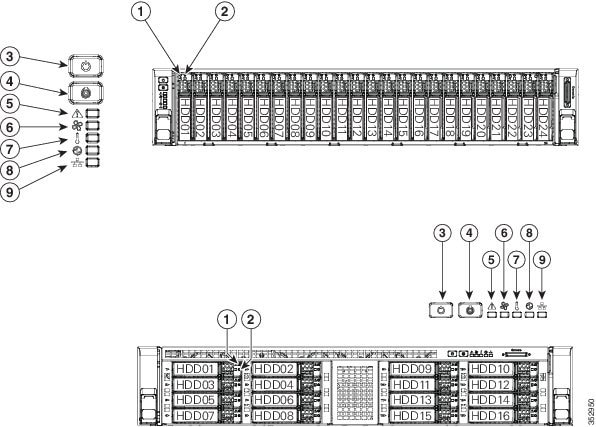
Figure 3-1 shows the front panel LEDs. Table 3-1 defines the LED states.
The small form factor (SFF) drives, 24-drive version and the SFF drives, 16-drive version are shown.
|
|
Hard drive fault LED (on each drive tray) Note: NVMe PCIe SSDs drive tray LEDs have slightly different behavior. See Table 3-1 for the LED states. |
|
|
|
|
|
||
|
|
|
||
|
|
|
||
|
|
|
|
|
|
|
|---|---|---|
| Note: If your controller is a Cisco UCS RAID SAS 9300-8i or 9300-8e HBA, see Cisco UCS SAS 9300-8e HBA Considerations for differing LED behavior. |
||
|
||
– – – |
||
Rear Panel LEDs and Buttons
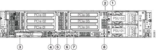
Figure 3-2 shows the rear panel LEDs and buttons. Table 3-2 defines the LED states.
Figure 3-2 Rear Panel LEDs and Buttons
|
|
|
||
|
|
|
||
|
|
Optional mLOM card LEDs |
|
|
|
|
|
|
|
|
|
|---|---|---|
| This is a summary; for advanced power supply LED information, see Table 3-3 . |
|
|
| This is a summary; for advanced power supply LED information, see Table 3-3 . |
||
In Table 3-3 , read the status and fault LED states together in each row to determine the event that cause this combination.
|
|
|
|
|---|---|---|
Internal Diagnostic LEDs
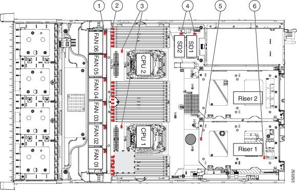
The server is equipped with a supercap voltage source that can activate internal component fault LEDs up to 30 minutes after AC power is removed. The server has internal fault LEDs for CPUs, DIMMs, fan modules, SD cards, the RTC battery, and the mLOM card.
To use these LEDs to identify a failed component, press the front or rear Unit Identification button (see Figure 3-1 or Figure 3-2) with AC power removed. An LED lights amber to indicate a faulty component.
See Figure 3-3 for the locations of these internal LEDs.
Figure 3-3 Internal Diagnostic LED Locations
|
|
|
||
|
|
DIMM fault LEDs (one directly in front of each DIMM socket on the motherboard) |
|
|
|
|
|
|
|
|
|---|---|
Preparing for Server Component Installation
This section describes how to prepare for component installation, and it includes the following topics:
- Required Equipment
- Shutting Down and Powering Off the Server
- Removing and Replacing the Server Top Cover
- Serial Number Location
- Hot-Swap or Hot-Plug Replacement
Required Equipment
The following equipment is used to perform the procedures in this chapter:
Shutting Down and Powering Off the Server
The server can run in two power modes:
- Main power mode—Power is supplied to all server components and any operating system on your drives can run.
- Standby power mode—Power is supplied only to the service processor and the cooling fans and it is safe to power off the server from this mode.
You can invoke a graceful shutdown or a hard shutdown by using either of the following methods:
- Use the Cisco IMC management interface.
- Use the Power button on the server front panel. To use the Power button, follow these steps:
Step 1![]() Check the color of the Power Status LED (see the “Front Panel LEDs” section).
Check the color of the Power Status LED (see the “Front Panel LEDs” section).
- Green—The server is in main power mode and must be shut down before it can be safely powered off. Go to Step 2.
- Amber—The server is already in standby mode and can be safely powered off. Go to Step 3.
Step 2![]() Invoke either a graceful shutdown or a hard shutdown:
Invoke either a graceful shutdown or a hard shutdown:

- Graceful shutdown—Press and release the Power button. The operating system performs a graceful shutdown and the server goes to standby mode, which is indicated by an amber Power Status LED.
- Emergency shutdown—Press and hold the Power button for 4 seconds to force the main power off and immediately enter standby mode.
Step 3![]() Disconnect the power cords from the power supplies in your server to completely power off the server.
Disconnect the power cords from the power supplies in your server to completely power off the server.
Removing and Replacing the Server Top Cover
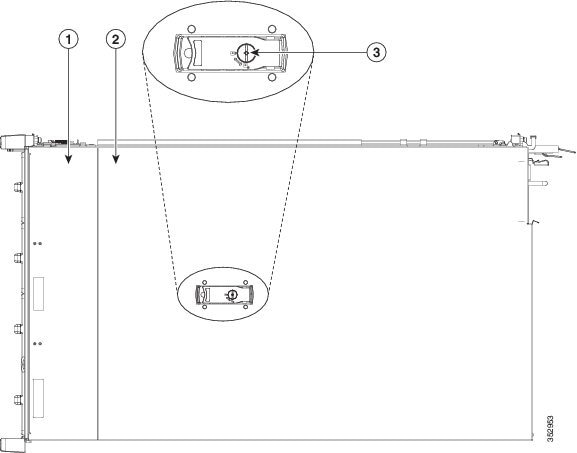
Step 1![]() Remove the top cover (see Figure 3-4).
Remove the top cover (see Figure 3-4).
a.![]() If the cover latch is locked, use a screwdriver to turn the lock 90-degrees counterclockwise to unlock it. See Figure 3-4.
If the cover latch is locked, use a screwdriver to turn the lock 90-degrees counterclockwise to unlock it. See Figure 3-4.
b.![]() Lift on the end of the latch that has the green finger grip. The cover is pushed back to the open position as you lift the latch.
Lift on the end of the latch that has the green finger grip. The cover is pushed back to the open position as you lift the latch.
c.![]() Lift the top cover straight up from the server and set it aside.
Lift the top cover straight up from the server and set it aside.

Note![]() The latch must be in the fully open position when you set the cover back in place, which allows the opening in the latch to sit over a peg that is on the fan tray.
The latch must be in the fully open position when you set the cover back in place, which allows the opening in the latch to sit over a peg that is on the fan tray.
a.![]() With the latch in the fully open position, place the cover on top of the server about one-half inch (1.27 cm) behind the lip of the front cover panel. The opening in the latch should fit over the peg that sticks up from the fan tray.
With the latch in the fully open position, place the cover on top of the server about one-half inch (1.27 cm) behind the lip of the front cover panel. The opening in the latch should fit over the peg that sticks up from the fan tray.
b.![]() Press the cover latch down to the closed position. The cover is pushed forward to the closed position as you push down the latch.
Press the cover latch down to the closed position. The cover is pushed forward to the closed position as you push down the latch.
c.![]() If desired, lock the latch by using a screwdriver to turn the lock 90-degrees clockwise.
If desired, lock the latch by using a screwdriver to turn the lock 90-degrees clockwise.
Figure 3-4 Removing the Top Cover
|
|
|
||
|
|
|
Serial Number Location
The serial number (SN) for the server is printed on a label on the top of the server, near the front.
Hot-Swap or Hot-Plug Replacement
Some components can be removed and replaced without powering off and removing AC power from the server.
- Hot-swap replacement—You do not have to precondition or shut down the component in the software before you remove it for the following components:
–![]() SAS/SATA hard drives or SSDs
SAS/SATA hard drives or SSDs
Installing or Replacing Server Components

Warning![]() Blank faceplates and cover panels serve three important functions: they prevent exposure to hazardous voltages and currents inside the chassis; they contain electromagnetic interference (EMI) that might disrupt other equipment; and they direct the flow of cooling air through the chassis. Do not operate the system unless all cards, faceplates, front covers, and rear covers are in place.
Blank faceplates and cover panels serve three important functions: they prevent exposure to hazardous voltages and currents inside the chassis; they contain electromagnetic interference (EMI) that might disrupt other equipment; and they direct the flow of cooling air through the chassis. Do not operate the system unless all cards, faceplates, front covers, and rear covers are in place.
Statement 1029

Tip![]() You can press the Unit Identification button on the front panel or rear panel to turn on a flashing Unit Identification LED on the front and rear panels of the server. This button allows you to locate the specific server that you are servicing when you go to the opposite side of the rack. You can also activate these LEDs remotely by using the Cisco IMC interface. See the “Status LEDs and Buttons” section for locations of these LEDs.
You can press the Unit Identification button on the front panel or rear panel to turn on a flashing Unit Identification LED on the front and rear panels of the server. This button allows you to locate the specific server that you are servicing when you go to the opposite side of the rack. You can also activate these LEDs remotely by using the Cisco IMC interface. See the “Status LEDs and Buttons” section for locations of these LEDs.
This section describes how to install and replace server components, and it includes the following topics:
- Replaceable Component Locations
- Replacing SAS/SATA Hard Drives or Solid State Drives
- Replacing a 2.5-Inch Form-Factor NVMe PCIe SSDs
- Replacing an HHHL Form-Factor NVMe Solid State Drive
- Replacing Fan Modules
- Replacing DIMMs
- Replacing CPUs and Heatsinks
- Replacing a SATA Interposer Board
- Replacing a Cisco Modular RAID Controller Card
- Replacing a Modular RAID Controller Transportable Memory Module (TMM)
- Replacing the Supercap Power Module (RAID Backup Battery)
- Replacing a Software RAID 5 Key Module
- Replacing the Motherboard RTC Battery
- Replacing an Internal SD Card
- Enabling or Disabling the Internal USB Port
- Replacing a PCIe Riser
- Replacing a PCIe Card
- Installing an NVIDIA GPU Card
- Replacing Internal SATA Boot Drives
- Installing a Trusted Platform Module (TPM)
- Replacing Power Supplies
- Replacing an mLOM Card
Replaceable Component Locations
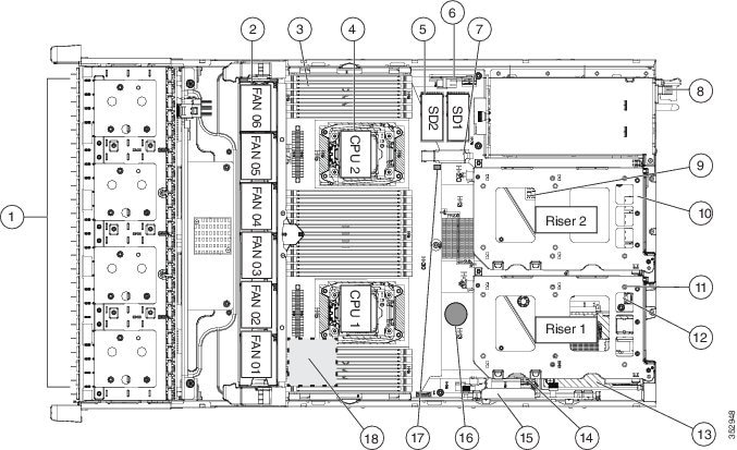
Figure 3-5 shows the locations of the components that are supported as field-replaceable. The view shown is from the top down, with the top covers and air baffle removed.
Figure 3-5 Replaceable Component Locations
|
|
Drives bays. All drive bays support SAS/SATA drives. SFF, 8-, 16-, and 24-drive versions only: Drive bays 1 and 2 support SAS/SATA drives and NVMe PCIe SSDs. NVMe drives require a PCIe interposer board for PCIe bus connection (see item 6). |
|
|
|
|
|
PCIe riser 1 (PCIe slots 1, 2, 3*) *Slot 3 not present in all versions. See Replacing a PCIe Card for riser options and slot specifications. |
|
|
|
|
SATA boot drives (two sockets available only on PCIe riser 1 option 1C) |
|
|
|
|
||
|
|
|
||
|
|
|
Cisco modular RAID controller PCIe slot |
|
|
|
|
||
|
|
|
||
|
|
Trusted platform module (TPM) socket on motherboard, under PCIe riser 2 |
|
Supercap power module (RAID backup) mounting location on air baffle (not shown) |
The Technical Specifications Sheets for all versions of this server, which include supported component part numbers, are at Cisco UCS Servers Technical Specifications Sheets.
Replacing SAS/SATA Hard Drives or Solid State Drives
SAS/SATA Drive Population Guidelines
The server is orderable in four different versions, each with one of four different front panel/backplane configurations:
- Cisco UCS C240 M4—Small form-factor (SFF) drives with 24-drive backplane and expander.
This version holds up to 24 2.5-inch SAS/SATA hard drives or solid state drives (SSDs). SAS/SATA drives are hot-swappable. - Cisco UCS C240 M4—SFF drives, with 16-drive backplane and integrated expander.
This version holds up to 16 2.5-inch SAS/SATA hard drives or solid state drives. SAS/SATA drives are hot-swappable. - Cisco UCS C240 M4—SFF drives, with 8-drive direct-connect backplane and no expander.
This version holds up to 8 2.5-inch SAS/SATA hard drives or solid state drives. SAS/SATA drives are hot-swappable. - Cisco UCS C240 M4—Large form-factor (LFF) drives, with 12-drive backplane and integrated expander. This version holds up to 12 3.5-inch SAS/SATA hard drives. SAS/SATA drives are hot-swappable.
Note![]() You cannot change the backplane type after-factory. To change a front panel/backplane configuration, a chassis replacement is required.
You cannot change the backplane type after-factory. To change a front panel/backplane configuration, a chassis replacement is required.
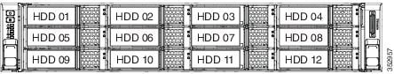
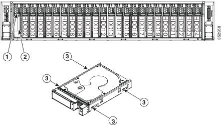
The drive-bay numbering for all server versions is shown in Figure 3-6 through Figure 3-9.
Figure 3-6 Drive Numbering, SFF Drives, 24-Drive Version
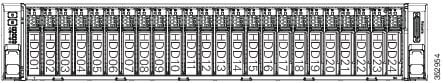
Figure 3-7 Drive Numbering, SFF Drives, 16-Drive Version
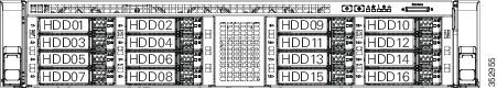
Figure 3-8 Drive Numbering, SFF Drives, 8-Drive Version
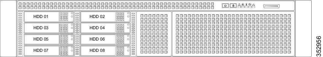
Figure 3-9 Drive Numbering, LFF Drives, 12-Drive Version
Observe these drive population guidelines for optimal performance:
- When populating drives, add drives in the lowest numbered bays first.
- Keep an empty drive blanking tray in any unused bays to ensure optimal airflow and cooling.
- You can mix hard drives and solid state drives in the same server. However, you cannot configure a logical volume (virtual drive) that contains a mix of hard drives and SSDs. That is, when you create a logical volume, it must contain all hard drives or all SSDs.
4K Sector Format Drives Considerations
- You must boot 4K sector format drives in UEFI mode, not legacy mode. See Setting Up Booting in UEFI Mode in the BIOS Setup Utility or Setting Up Booting in UEFI Mode in the Cisco IMC GUI.
- Do not configure 4K sector format and 512-byte sector format drives as part of the same RAID volume.
- Operating system support on 4K sector drives is as follows: Windows: Win2012 and Win2012R2; Linux: RHEL 6.5, 6.6, 6.7, 7.0, 7.2; SLES 11 SP3, and SLES 12. ESXi/Vmware is not supported.
Setting Up Booting in UEFI Mode in the BIOS Setup Utility
Step 1![]() Enter the BIOS setup utility by pressing the F2 key when prompted during bootup.
Enter the BIOS setup utility by pressing the F2 key when prompted during bootup.
Step 2![]() Go to the Boot Options tab.
Go to the Boot Options tab.
Step 3![]() Set UEFI Boot Options to Enabled.
Set UEFI Boot Options to Enabled.
Step 4![]() Under Boot Option Priorities, set your OS installation media (such as a virtual DVD) as your
Under Boot Option Priorities, set your OS installation media (such as a virtual DVD) as your
Boot Option #1.
Step 5![]() Go to the Advanced tab.
Go to the Advanced tab.
Step 6![]() Select LOM and PCIe Slot Configuration.
Select LOM and PCIe Slot Configuration.
Step 7![]() Set the PCIe Slot ID: HBA Option ROM to UEFI Only.
Set the PCIe Slot ID: HBA Option ROM to UEFI Only.
Step 8![]() Press F10 to save changes and exit the BIOS setup utility. Allow the server to reboot.
Press F10 to save changes and exit the BIOS setup utility. Allow the server to reboot.
Step 9![]() After the OS installs, verify the installation:
After the OS installs, verify the installation:
a.![]() Enter the BIOS setup utility by pressing the F2 key when prompted during bootup.
Enter the BIOS setup utility by pressing the F2 key when prompted during bootup.
b.![]() Go to the Boot Options tab.
Go to the Boot Options tab.
c.![]() Under Boot Option Priorities, verify that the OS you installed is listed as your Boot Option #1.
Under Boot Option Priorities, verify that the OS you installed is listed as your Boot Option #1.
Setting Up Booting in UEFI Mode in the Cisco IMC GUI
Step 1![]() Use a web browser and the IP address of the server to log into the Cisco IMC GUI management interface.
Use a web browser and the IP address of the server to log into the Cisco IMC GUI management interface.
Step 2![]() Navigate to Server > BIOS.
Navigate to Server > BIOS.
Step 3![]() Under Actions, click Configure BIOS.
Under Actions, click Configure BIOS.
Step 4![]() In the Configure BIOS Parameters dialog, select the Advanced tab.
In the Configure BIOS Parameters dialog, select the Advanced tab.
Step 5![]() Go to the LOM and PCIe Slot Configuration section.
Go to the LOM and PCIe Slot Configuration section.
Step 6![]() Set the PCIe Slot: HBA Option ROM to UEFI Only.
Set the PCIe Slot: HBA Option ROM to UEFI Only.
Step 7![]() Click Save Changes. The dialog closes.
Click Save Changes. The dialog closes.
Step 8![]() Under BIOS Properties, set Configured Boot Order to UEFI.
Under BIOS Properties, set Configured Boot Order to UEFI.
Step 9![]() Under Actions, click Configure Boot Order.
Under Actions, click Configure Boot Order.
Step 10![]() In the Configure Boot Order dialog, click Add Local HDD.
In the Configure Boot Order dialog, click Add Local HDD.
Step 11![]() In the Add Local HDD dialog, enter the information for the 4K sector format drive and make it first in the boot order.
In the Add Local HDD dialog, enter the information for the 4K sector format drive and make it first in the boot order.
Step 12![]() Save changes and reboot the server. The changes you made will be visible after the system reboots.
Save changes and reboot the server. The changes you made will be visible after the system reboots.
Replacing SAS/SATA Drives
Tip![]() You do not have to shut down or power off the server to replace SAS/SATA hard drives or solid state drives (SSDs) because they are hot-swappable. To replace an NVMe PCIe SSD drive, which must be shut down before removal, see Replacing a 2.5-Inch Form-Factor NVMe PCIe SSDs.
You do not have to shut down or power off the server to replace SAS/SATA hard drives or solid state drives (SSDs) because they are hot-swappable. To replace an NVMe PCIe SSD drive, which must be shut down before removal, see Replacing a 2.5-Inch Form-Factor NVMe PCIe SSDs.
Step 1![]() Remove the drive that you are replacing or remove a blank drive tray from an empty bay:
Remove the drive that you are replacing or remove a blank drive tray from an empty bay:
a.![]() Press the release button on the face of the drive tray. See Figure 3-10.
Press the release button on the face of the drive tray. See Figure 3-10.
b.![]() Grasp and open the ejector lever and then pull the drive tray out of the slot.
Grasp and open the ejector lever and then pull the drive tray out of the slot.
c.![]() If you are replacing an existing drive, remove the four drive-tray screws that secure the drive to the tray and then lift the drive out of the tray.
If you are replacing an existing drive, remove the four drive-tray screws that secure the drive to the tray and then lift the drive out of the tray.
a.![]() Place a new drive in the empty drive tray and replace the four drive-tray screws.
Place a new drive in the empty drive tray and replace the four drive-tray screws.
b.![]() With the ejector lever on the drive tray open, insert the drive tray into the empty drive bay.
With the ejector lever on the drive tray open, insert the drive tray into the empty drive bay.
c.![]() Push the tray into the slot until it touches the backplane, and then close the ejector lever to lock the drive in place.
Push the tray into the slot until it touches the backplane, and then close the ejector lever to lock the drive in place.
|
|
|
||
|
|
|
Replacing a 2.5-Inch Form-Factor NVMe PCIe SSDs
This section is for replacing 2.5-inch small form-factor (SFF) NVMe PCIe SSDs in front-panel drive bays. To replace HHHL form-factor NVMe PCIe SSDs in the PCIe slots, see Replacing an HHHL Form-Factor NVMe Solid State Drive.
2.5-Inch Form-Factor NVMe PCIe SSD Population Guidelines
The SFF versions of the server (8-, 16-, and 24-drive) support up to two NVMe SFF 2.5-inch SSDs in drive bays 1 and 2 only.
2.5-Inch Form-Factor NVME PCIe SSD Requirements and Restrictions
Observe these requirements for NVMe SFF 2.5-inch SSDs:
- The SFF drives versions of the server (8-drives, 16-drives, or 24-drives).
- The server must have two CPUs. The PCIe interposer board is not available in a single-CPU system.
- The PCIe interposer board with bundled cables for your server version:
–![]() SFF 8- or SFF 16-drives server: UCSC-IP-SSD-240M4
SFF 8- or SFF 16-drives server: UCSC-IP-SSD-240M4
–![]() SFF 24-drives server: UCSC-IP-SSD-240M4B
SFF 24-drives server: UCSC-IP-SSD-240M4B
Observe these restrictions for NVMe SFF 2.5-inch SSDs:
- You can boot (UEFI only) from an NVMe SFF 2.5-inch SSD only with Cisco IMC 2.0(13) or later server firmware. For Cisco UCS Manager-integrated servers, booting is supported only with Cisco UCS Manager 3.1(2) or later software.
- NVMe SFF 2.5-inch SSDs support booting only in UEFI mode. Legacy boot is not supported.
- You cannot control an NVMe SFF 2.5-inch SSD with a SAS RAID controller because they communicate with the server via the PCIe bus.
- You can combine NVMe SFF 2.5-inch SSDs and HHHL form-factor SSDs in the same system, but the same partner brand must be used. For example, two Intel NVMe SFF 2.5-inch SSDs and six HHHL form-factor HGST SSDs is an invalid configuration. A valid configuration is two HGST NVMe SFF 2.5-inch SSDs and six HGST HHHL form-factor SSDs.
- UEFI boot is supported in the five operating systems listed in Table 3-5 , when your server is running Cisco IMC 2.0(13) or later firmware. Refer to this table for OS-informed hot-insertion and hot-removal support by operating system:
|
|
|
|
|
|
|
|
|---|---|---|---|---|---|---|
Enabling Hot-Plug Support in the System BIOS
In Cisco IMC 2.0(13) and later, hot-plug (OS-informed hot-insertion and hot-removal) is disabled in the system BIOS by default.
Enabling Hot-Plug Support in the BIOS Setup Utility
Step 1![]() Enter the BIOS setup utility by pressing the F2 key when prompted during bootup.
Enter the BIOS setup utility by pressing the F2 key when prompted during bootup.
Step 2![]() Locate the setting: Advanced > PCI Subsystem Settings > NVMe SSD Hot-Plug Support.
Locate the setting: Advanced > PCI Subsystem Settings > NVMe SSD Hot-Plug Support.
Step 3![]() Set the value to Enabled.
Set the value to Enabled.
Step 4![]() Save your changes and exit the utility.
Save your changes and exit the utility.
Enabling Hot-Plug Support in the Cisco IMC GUI
Step 1![]() Use a browser to log into the Cisco IMC GUI for the system.
Use a browser to log into the Cisco IMC GUI for the system.
Step 2![]() Navigate to Compute > BIOS > Advanced > PCI Configuration.
Navigate to Compute > BIOS > Advanced > PCI Configuration.
Step 3![]() Set NVME SSD Hot-Plug Support to Enabled.
Set NVME SSD Hot-Plug Support to Enabled.
Step 4![]() Save your changes and exit the software.
Save your changes and exit the software.
Replacing an NVMe SFF 2.5-Inch PCIe SSD
Note![]() OS-surprise removal is not supported. OS-informed hot-insertion and hot-removal are supported only with Cisco IMC release 2.0(13) and later and they depend on your OS version. See Table 3-5 for support by OS.
OS-surprise removal is not supported. OS-informed hot-insertion and hot-removal are supported only with Cisco IMC release 2.0(13) and later and they depend on your OS version. See Table 3-5 for support by OS.
Note![]() OS-informed hot-insertion and hot-removal must be enabled in the system BIOS. See Enabling Hot-Plug Support in the System BIOS.
OS-informed hot-insertion and hot-removal must be enabled in the system BIOS. See Enabling Hot-Plug Support in the System BIOS.
For information about drive tray LEDs, see Front Panel LEDs.
Step 1![]() Remove an existing NVMe SFF 2.5-inch SSD:
Remove an existing NVMe SFF 2.5-inch SSD:
a.![]() Shut down the NVMe SFF 2.5-inch SSD to initiate an OS-informed removal. Use your operating system interface to shut down the drive, and then observe the drive-tray LED:
Shut down the NVMe SFF 2.5-inch SSD to initiate an OS-informed removal. Use your operating system interface to shut down the drive, and then observe the drive-tray LED:
–![]() Green—The drive is in use and functioning properly. Do not remove.
Green—The drive is in use and functioning properly. Do not remove.
–![]() Green, blinking—the driver is unloading following a shutdown command. Do not remove.
Green, blinking—the driver is unloading following a shutdown command. Do not remove.
–![]() Off—The drive is not in use and can be safely removed.
Off—The drive is not in use and can be safely removed.
b.![]() Press the release button on the face of the drive tray. See Figure 3-10.
Press the release button on the face of the drive tray. See Figure 3-10.
c.![]() Grasp and open the ejector lever and then pull the drive tray out of the slot.
Grasp and open the ejector lever and then pull the drive tray out of the slot.
d.![]() If you are replacing an existing SSD, remove the four drive tray screws that secure the SSD to the tray and then lift the SSD out of the tray.
If you are replacing an existing SSD, remove the four drive tray screws that secure the SSD to the tray and then lift the SSD out of the tray.
Note![]() If this is the first time that NVMe SFF 2.5-inch SSDs are being installed in the server, you must install a PCIe interposer board and connect its cables before installing the drive. See Installing a PCIe Interposer Board For NVMe SFF 2.5-inch SSDs.
If this is the first time that NVMe SFF 2.5-inch SSDs are being installed in the server, you must install a PCIe interposer board and connect its cables before installing the drive. See Installing a PCIe Interposer Board For NVMe SFF 2.5-inch SSDs.
Step 2![]() Install a new NVMe SFF 2.5-inch SSD:
Install a new NVMe SFF 2.5-inch SSD:
a.![]() Place a new SSD in the empty drive tray and replace the four drive tray screws.
Place a new SSD in the empty drive tray and replace the four drive tray screws.
b.![]() With the ejector lever on the drive tray open, insert the drive tray into the empty drive bay.
With the ejector lever on the drive tray open, insert the drive tray into the empty drive bay.
c.![]() Push the tray into the slot until it touches the backplane, and then close the ejector lever to lock the drive in place.
Push the tray into the slot until it touches the backplane, and then close the ejector lever to lock the drive in place.
Step 3![]() Observe the drive-tray LED and wait until it returns to solid green before accessing the drive:
Observe the drive-tray LED and wait until it returns to solid green before accessing the drive:
- Off—The drive is not in use.
- Green, blinking—the driver is initializing following hot-plug insertion.
- Green—The drive is in use and functioning properly.
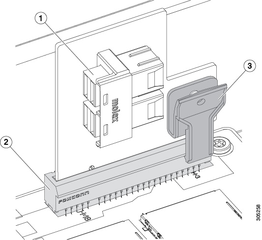
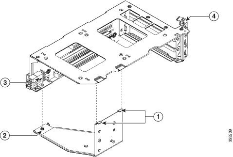
Installing a PCIe Interposer Board For NVMe SFF 2.5-inch SSDs
A PCIe interposer board is used to provide communication with the PCIe bus from the NVMe SFF 2.5-inch SSDs in the front panel bays. Use the correct interposer board, with bundled cables, for your version of the server:
Figure 3-11 PCIe Interposer Board
|
|
|
||
|
|
|
Step 1![]() Power off the server as described in Shutting Down and Powering Off the Server.
Power off the server as described in Shutting Down and Powering Off the Server.
Step 2![]() Slide the server out the front of the rack far enough so that you can remove the top cover. You might have to detach cables from the rear panel to provide clearance.
Slide the server out the front of the rack far enough so that you can remove the top cover. You might have to detach cables from the rear panel to provide clearance.
Step 3![]() Remove the top cover as described in Removing and Replacing the Server Top Cover.
Remove the top cover as described in Removing and Replacing the Server Top Cover.
Step 4![]() Install a new PCIe interposer board:
Install a new PCIe interposer board:
a.![]() Locate the PCIe interposer board socket on the motherboard (see Figure 3-12).
Locate the PCIe interposer board socket on the motherboard (see Figure 3-12).
b.![]() Pinch the securing clip on the board while you insert the board to the socket as shown in Figure 3-11.
Pinch the securing clip on the board while you insert the board to the socket as shown in Figure 3-11.
c.![]() Carefully push down to seat the board, then release the securing clip.
Carefully push down to seat the board, then release the securing clip.
Step 5![]() Connect the two cables that come with the interposer board:
Connect the two cables that come with the interposer board:
a.![]() Connect the double-connector end of the cable to the interposer board (see Figure 3-11).
Connect the double-connector end of the cable to the interposer board (see Figure 3-11).
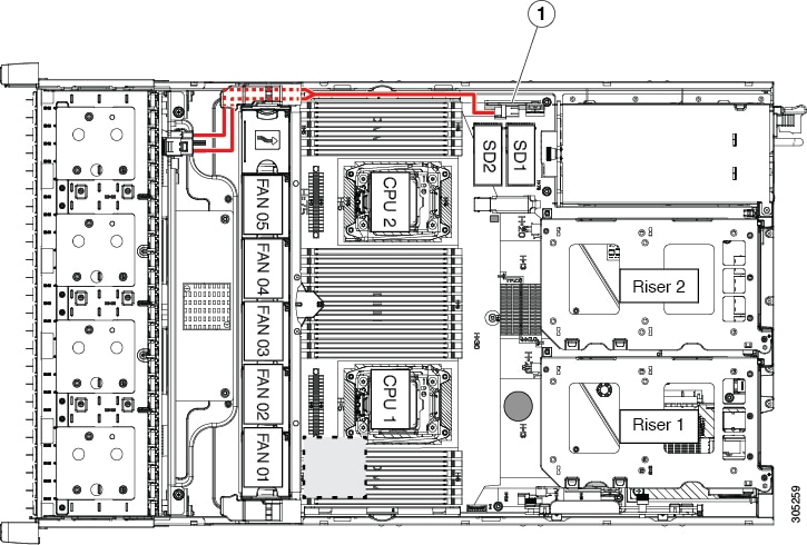
b.![]() Route the cables to the front of the server using the recommended path through the chassis cable guides as shown in Figure 3-12.
Route the cables to the front of the server using the recommended path through the chassis cable guides as shown in Figure 3-12.
c.![]() Connect the two ends of the cable to the PCIe connectors on the drive backplane.
Connect the two ends of the cable to the PCIe connectors on the drive backplane.
Connect the cable labeled Port A to the Port A connector; connect the cable labeled Port B to the Port B connector.
Step 7![]() Replace the server in the rack, replace cables, and then power on the server by pressing the Power button.
Replace the server in the rack, replace cables, and then power on the server by pressing the Power button.
Figure 3-12 PCIe Interposer Board Cabling
|
|
|
Replacing an HHHL Form-Factor NVMe Solid State Drive
The half-height, half-length- (HHHL-) format NVMe PCIe SSDs install to the PCIe riser slots. To install a 2.5-inch form-factor NVME SSD in the front-panel drive bays, see Replacing a 2.5-Inch Form-Factor NVMe PCIe SSDs.
HHHL Form-Factor NVMe SSD Population Guidelines
Observe the following population guidelines when installing HHHL form-factor NVMe SSDs:
- Two-CPU systems—You can populate up to 6 HHHL form-factor SSDs, using PCIe slots 1 – 6.
- One-CPU systems—In a single-CPU system, PCIe riser 2, which has slots 4–6, is not available. Therefore, the maximum number of HHHL form-factor SSDs you can populate is 3, in PCIe slots 1–3.
|
|
|
|---|---|
HHHL Form-Factor NVME SSD Requirements and Restrictions
Observe these requirements for HHHL form-factor NVMe SSDs:
- All versions of the server support HHHL form-factor NVMe SSDs (LFF 12-drives or SFF 8-drives, 16-drives, or 24-drives server).
Observe these restrictions for HHHL form-factor NVMe PCIe SSDs:
- You cannot boot from an HHHL form-factor NVMe SSD.
- You cannot control an HHHL form-factor NVMe PCIe SSD with a SAS RAID controller because they communicate with the server via the PCIe bus.
- You can combine NVMe SFF 2.5-inch SSDs and HHHL form-factor SSDs in the same system, but the same partner brand must be used. For example, two Intel NVMe SFF 2.5-inch SSDs and six HHHL form-factor HGST SSDs is an invalid configuration. A valid configuration is two HGST NVMe SFF 2.5-inch SSDs and six HGST HHHL form-factor SSDs.
Replacing an HHHL Form-Factor NVMe SSD
Note![]() In a single-CPU server, PCIe riser 2 (PCIe slots 4–6) is not available.
In a single-CPU server, PCIe riser 2 (PCIe slots 4–6) is not available.
Step 1![]() Shut down and power off the server as described in Shutting Down and Powering Off the Server.
Shut down and power off the server as described in Shutting Down and Powering Off the Server.
Step 2![]() Slide the server out the front of the rack far enough so that you can remove the top cover. You might have to detach cables from the rear panel to provide clearance.
Slide the server out the front of the rack far enough so that you can remove the top cover. You might have to detach cables from the rear panel to provide clearance.
Step 3![]() Remove the top cover as described in Removing and Replacing the Server Top Cover.
Remove the top cover as described in Removing and Replacing the Server Top Cover.
Step 4![]() Remove an existing HHHL form-factor NVMe drive (or a blanking panel) from the PCIe riser:
Remove an existing HHHL form-factor NVMe drive (or a blanking panel) from the PCIe riser:
a.![]() Lift straight up on both ends of the riser to disengage its circuit board from the socket on the motherboard. Set the riser on an antistatic mat.
Lift straight up on both ends of the riser to disengage its circuit board from the socket on the motherboard. Set the riser on an antistatic mat.
b.![]() On the bottom of the riser, loosen the single thumbscrew that holds the securing plate (see Figure 3-13).
On the bottom of the riser, loosen the single thumbscrew that holds the securing plate (see Figure 3-13).
c.![]() Swing open the securing plate and remove it from the riser to provide access.
Swing open the securing plate and remove it from the riser to provide access.
d.![]() Swing open the card-tab retainer that secures the back-panel tab of the card (see Figure 3-13).
Swing open the card-tab retainer that secures the back-panel tab of the card (see Figure 3-13).
e.![]() Pull evenly on both ends of the HHHL form-factor NVMe SSD to disengage it from the socket on the PCIe riser (or remove a blanking panel) and then set the card aside.
Pull evenly on both ends of the HHHL form-factor NVMe SSD to disengage it from the socket on the PCIe riser (or remove a blanking panel) and then set the card aside.
Step 5![]() Install an HHHL form-factor NVMe SSD:
Install an HHHL form-factor NVMe SSD:
a.![]() Align the new HHHL form-factor NVMe SSD with the empty socket on the PCIe riser.
Align the new HHHL form-factor NVMe SSD with the empty socket on the PCIe riser.
b.![]() Push down evenly on both ends of the card until it is fully seated in the socket.
Push down evenly on both ends of the card until it is fully seated in the socket.
c.![]() Close the card-tab retainer (see Figure 3-13).
Close the card-tab retainer (see Figure 3-13).
d.![]() Return the securing plate to the riser. Insert the two hinge-tabs into the two slots on the riser, and then swing the securing plate closed.
Return the securing plate to the riser. Insert the two hinge-tabs into the two slots on the riser, and then swing the securing plate closed.
e.![]() Tighten the single thumbscrew on the bottom of the securing plate.
Tighten the single thumbscrew on the bottom of the securing plate.
f.![]() Position the PCIe riser over its socket on the motherboard and over its alignment features in the chassis (see Figure 3-27).
Position the PCIe riser over its socket on the motherboard and over its alignment features in the chassis (see Figure 3-27).
g.![]() Carefully push down on both ends of the PCIe riser to fully engage its circuit board connector with the socket on the motherboard.
Carefully push down on both ends of the PCIe riser to fully engage its circuit board connector with the socket on the motherboard.
Step 7![]() Replace the server in the rack, replace cables, and then power on the server by pressing the Power button.
Replace the server in the rack, replace cables, and then power on the server by pressing the Power button.
Figure 3-13 PCIe Riser Securing Features (Three-Slot Riser Shown)
|
|
|
||
|
|
Securing plate thumbscrew (knob not visible on underside of plate) |
|
Replacing Fan Modules
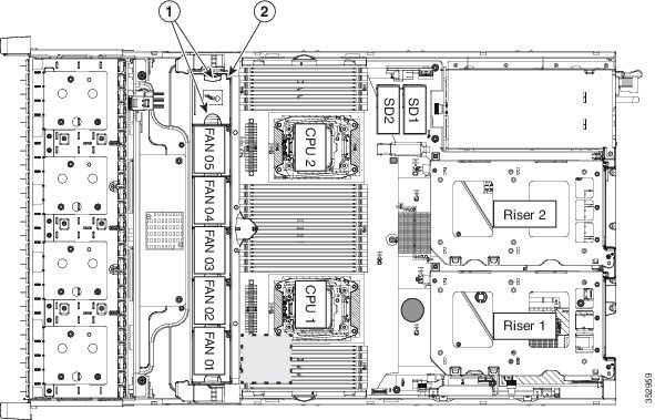
The six hot-swappable fan modules in the server are numbered as follows when you are facing the front of the server.
Figure 3-14 Fan Module Numbering
Tip![]() A fault LED is on the top of each fan module that lights amber if the fan module fails. To operate these LEDs from the SuperCap power source, remove AC power cords and then press the Unit Identification button. See also Internal Diagnostic LEDs.
A fault LED is on the top of each fan module that lights amber if the fan module fails. To operate these LEDs from the SuperCap power source, remove AC power cords and then press the Unit Identification button. See also Internal Diagnostic LEDs.
Step 1![]() Slide the server out the front of the rack far enough so that you can remove the top cover. You might have to detach cables from the rear panel to provide clearance.
Slide the server out the front of the rack far enough so that you can remove the top cover. You might have to detach cables from the rear panel to provide clearance.
Step 2![]() Remove the top cover as described in Removing and Replacing the Server Top Cover.
Remove the top cover as described in Removing and Replacing the Server Top Cover.
Step 3![]() Identify a faulty fan module by looking for a fan fault LED that is lit amber (see Figure 3-15).
Identify a faulty fan module by looking for a fan fault LED that is lit amber (see Figure 3-15).
Step 4![]() Remove a fan module that you are replacing (see Figure 3-15):
Remove a fan module that you are replacing (see Figure 3-15):
a.![]() Grasp the top of the fan and pinch the green plastic latch toward the center.
Grasp the top of the fan and pinch the green plastic latch toward the center.
b.![]() Lift straight up to remove the fan module from the server.
Lift straight up to remove the fan module from the server.
Step 5![]() Install a new fan module:
Install a new fan module:
a.![]() Set the new fan module in place, aligning the connector on the bottom of the fan module with the connector on the motherboard.
Set the new fan module in place, aligning the connector on the bottom of the fan module with the connector on the motherboard.
Note![]() The arrow label on the top of the fan module, which indicates the direction of airflow, should point toward the rear of the server.
The arrow label on the top of the fan module, which indicates the direction of airflow, should point toward the rear of the server.
b.![]() Press down gently on the fan module until the latch clicks and locks in place.
Press down gently on the fan module until the latch clicks and locks in place.
Step 7![]() Replace the server in the rack.
Replace the server in the rack.
Figure 3-15 Fan Modules Latch and Fault LED
|
|
|
Replacing DIMMs
This section includes the following topics:
Note![]() To ensure the best server performance, it is important that you are familiar with memory performance guidelines and population rules before you install or replace the memory.
To ensure the best server performance, it is important that you are familiar with memory performance guidelines and population rules before you install or replace the memory.
Memory Performance Guidelines and Population Rules
This section describes the type of memory that the server requires and its effect on performance. The section includes the following topics:
DIMM Socket Numbering
Figure 3-16 shows the numbering of the DIMM sockets and CPUs.
Figure 3-16 CPUs and DIMM Socket Numbering on Motherboard
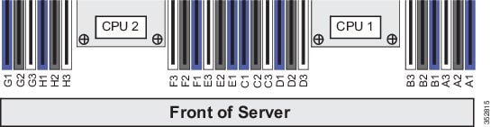
DIMM Population Rules
Observe the following guidelines when installing or replacing DIMMs:
–![]() CPU1 supports channels A, B, C, and D.
CPU1 supports channels A, B, C, and D.
–![]() CPU2 supports channels E, F, G, and H.
CPU2 supports channels E, F, G, and H.
–![]() A channel can operate with one, two, or three DIMMs installed.
A channel can operate with one, two, or three DIMMs installed.
–![]() If a channel has only one DIMM, populate slot 1 first (the blue slot).
If a channel has only one DIMM, populate slot 1 first (the blue slot).
–![]() Fill blue #1 slots in the channels first: A1, E1, B1, F1, C1, G1, D1, H1
Fill blue #1 slots in the channels first: A1, E1, B1, F1, C1, G1, D1, H1
–![]() Fill black #2 slots in the channels second: A2, E2, B2, F2, C2, G2, D2, H2
Fill black #2 slots in the channels second: A2, E2, B2, F2, C2, G2, D2, H2
–![]() Fill white #3 slots in the channels third: A3, E3, B3, F3, C3, G3, D3, H3
Fill white #3 slots in the channels third: A3, E3, B3, F3, C3, G3, D3, H3
- Any DIMM installed in a DIMM socket for which the CPU is absent is not recognized. In a single-CPU configuration, populate the channels for CPU1 only (A, B, C, D).
- Memory mirroring reduces the amount of memory available by 50 percent because only one of the two populated channels provides data. When memory mirroring is enabled, you must install DIMMs in sets of 4, 6, 8, or 12 as described in Memory Mirroring and RAS.
- NVIDIA K-Series and M-Series GPUs can support only less-than 1 TB memory in the server.
- NVIDIA P-Series GPUs can support 1 TB or more memory in the server.
- AMD FirePro S7150 X2 can support only less-than 1 TB memory in the server.
- Observe the DIMM mixing rules shown in Table 3-6 .
Memory Mirroring and RAS
The Intel E5-2600 CPUs within the server support memory mirroring only when an even number of channels are populated with DIMMs. If one or three channels are populated with DIMMs, memory mirroring is automatically disabled. Furthermore, if memory mirroring is used, DRAM size is reduced by 50 percent for reasons of reliability.
For details on populating recommended memory mirroring configurations, see the specification sheet for the server:
Lockstep Channel Mode
When you enable lockstep channel mode, each memory access is a 128-bit data access that spans four channels.
Lockstep channel mode requires that all four memory channels on a CPU must be populated identically with regard to size and organization. DIMM socket populations within a channel (for example, A1, A2, A3) do not have to be identical but the same DIMM slot location across all four channels must be populated the same.
For example, DIMMs in sockets A1, B1, C1, and D1 must be identical. DIMMs in sockets A2, B2, C2, and D2 must be identical. However, the A1-B1-C1-D1 DIMMs do not have to be identical with the A2-B2-C2-D2 DIMMs.
DIMM Replacement Procedure
Identifying a Faulty DIMM
Each DIMM socket has a corresponding DIMM fault LED, directly in front of the DIMM socket. See Figure 3-3 for the locations of these LEDs. The LEDs light amber to indicate a faulty DIMM. To operate these LEDs from the SuperCap power source, remove AC power cords and then press the Unit Identification button.
Replacing DIMMs
Step 1![]() Power off the server as described in Shutting Down and Powering Off the Server.
Power off the server as described in Shutting Down and Powering Off the Server.
Step 2![]() Slide the server out the front of the rack far enough so that you can remove the top cover. You might have to detach cables from the rear panel to provide clearance.
Slide the server out the front of the rack far enough so that you can remove the top cover. You might have to detach cables from the rear panel to provide clearance.
Step 3![]() Remove the top cover as described in Removing and Replacing the Server Top Cover.
Remove the top cover as described in Removing and Replacing the Server Top Cover.
Step 4![]() Remove the air baffle that sits over the DIMM sockets and set it aside.
Remove the air baffle that sits over the DIMM sockets and set it aside.
Step 5![]() Identify the faulty DIMM by observing the DIMM socket fault LEDs on the motherboard (see Figure 3-3).
Identify the faulty DIMM by observing the DIMM socket fault LEDs on the motherboard (see Figure 3-3).
Step 6![]() Remove the DIMMs that you are replacing. Open the ejector levers at both ends of the DIMM socket, and then lift the DIMM out of the socket.
Remove the DIMMs that you are replacing. Open the ejector levers at both ends of the DIMM socket, and then lift the DIMM out of the socket.
Note![]() Before installing DIMMs, see the population guidelines. See Memory Performance Guidelines and Population Rules.
Before installing DIMMs, see the population guidelines. See Memory Performance Guidelines and Population Rules.
a.![]() Align the new DIMM with the empty socket on the motherboard. Use the alignment key in the DIMM socket to correctly orient the DIMM.
Align the new DIMM with the empty socket on the motherboard. Use the alignment key in the DIMM socket to correctly orient the DIMM.
b.![]() Push down evenly on the top corners of the DIMM until it is fully seated and the ejector levers on both ends lock into place.
Push down evenly on the top corners of the DIMM until it is fully seated and the ejector levers on both ends lock into place.
Step 8![]() Replace the air baffle.
Replace the air baffle.
Step 10![]() Replace the server in the rack, replace cables, and then power on the server by pressing the Power button.
Replace the server in the rack, replace cables, and then power on the server by pressing the Power button.
Replacing CPUs and Heatsinks
Special Information For Upgrades to Intel Xeon v4 CPUs
The minimum software and firmware versions required for the server to support Intel v4 CPUs are as follows:
|
|
|
|---|---|
Note![]() Cisco UCS Manager Release 2.2(4) introduced a server pack feature that allows Intel v4 CPUs to run with Cisco UCS Manager Release 2.2(4) or later.
Cisco UCS Manager Release 2.2(4) introduced a server pack feature that allows Intel v4 CPUs to run with Cisco UCS Manager Release 2.2(4) or later.
The UCS Manager Capability Catalog must be updated to 2.2(7c) or later.
The server Cisco IMC/BIOS must be running the minimum version or later as described in Table 3-7.
Do one of the following actions:
- If your server’s firmware and/or Cisco UCS Manager software are already at the required levels shown in Table 3-7 , you can replace the CPU hardware by using the procedure in this section.
- If your server’s firmware and/or Cisco UCS Manager software is earlier than the required levels, use the instructions in the Cisco UCS C-Series Servers Upgrade Guide for Intel Xeon v4 CPUs to upgrade your software. After you upgrade the software, return to the procedure in this section as directed to replace the CPU hardware.
CPU Configuration Rules
This server has two CPU sockets. Each CPU supports four DIMM channels (12 DIMM sockets). See Figure 3-16.
- The server can operate with one CPU or with two identical CPUs installed.
- The minimum configuration is that the server must have at least CPU1 installed. Install CPU1 first, and then CPU2.
- The following restrictions apply when using a single-CPU configuration:
–![]() The maximum number of DIMMs is 12 (only CPU1 channels A, B, C, and D).
The maximum number of DIMMs is 12 (only CPU1 channels A, B, C, and D).
–![]() PCIe riser 2, which contains PCIe slots 4, 5, and 6 is unavailable.
PCIe riser 2, which contains PCIe slots 4, 5, and 6 is unavailable.
Replacing a CPU and Heatsink
Note![]() This server uses the new independent loading mechanism (ILM) CPU sockets, so no Pick-and-Place tools are required for CPU handling or installation. Always grasp the plastic frame on the CPU when handling.
This server uses the new independent loading mechanism (ILM) CPU sockets, so no Pick-and-Place tools are required for CPU handling or installation. Always grasp the plastic frame on the CPU when handling.
Step 1![]() Power off the server as described in Shutting Down and Powering Off the Server.
Power off the server as described in Shutting Down and Powering Off the Server.
Step 2![]() Slide the server out the front of the rack far enough so that you can remove the top cover. You might have to detach cables from the rear panel to provide clearance.
Slide the server out the front of the rack far enough so that you can remove the top cover. You might have to detach cables from the rear panel to provide clearance.
Step 3![]() Remove the top cover as described in Removing and Replacing the Server Top Cover.
Remove the top cover as described in Removing and Replacing the Server Top Cover.
Step 4![]() Remove the plastic air baffle that sits over the CPUs.
Remove the plastic air baffle that sits over the CPUs.
Step 5![]() Remove the heatsink that you are replacing:
Remove the heatsink that you are replacing:
a.![]() Use a Number 2 Phillips-head screwdriver to loosen the four captive screws that secure the heatsink.
Use a Number 2 Phillips-head screwdriver to loosen the four captive screws that secure the heatsink.
Note![]() Alternate loosening each screw evenly to avoid damaging the heatsink or CPU.
Alternate loosening each screw evenly to avoid damaging the heatsink or CPU.
b.![]() Lift the heatsink off of the CPU.
Lift the heatsink off of the CPU.
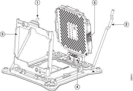
Step 6![]() Open the CPU retaining mechanism:
Open the CPU retaining mechanism:
a.![]() Unclip the first retaining latch labeled with the
Unclip the first retaining latch labeled with the  icon, and then unclip the second retaining latch labeled with the
  icon. See Figure 3-17.
b.![]() Open the hinged CPU cover plate.
Open the hinged CPU cover plate.
|
|
|
||
|
|
|
||
|
|
|
Step 7![]() Remove any existing CPU:
Remove any existing CPU:
a.![]() With the latches and hinged CPU cover plate open, swing the CPU in its hinged seat up to the open position, as shown in Figure 3-17.
With the latches and hinged CPU cover plate open, swing the CPU in its hinged seat up to the open position, as shown in Figure 3-17.
b.![]() Grasp the CPU by the finger-grips on its plastic frame and lift it up and out of the hinged CPU seat.
Grasp the CPU by the finger-grips on its plastic frame and lift it up and out of the hinged CPU seat.
c.![]() Set the CPU aside on an antistatic surface.
Set the CPU aside on an antistatic surface.
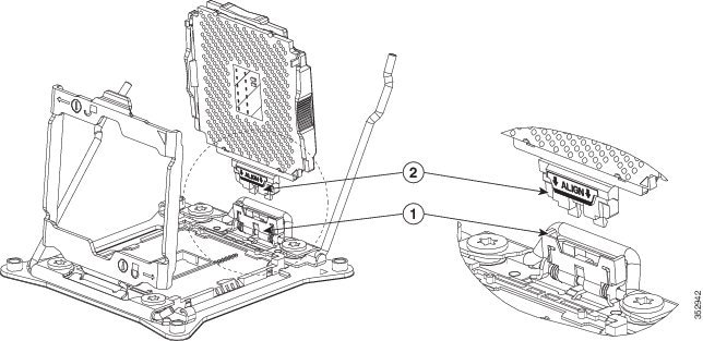
a.![]() Grasp the new CPU by the finger-grips on its plastic frame and align the tab on the frame that is labeled “ALIGN” with the hinged seat, as shown in Figure 3-18.
Grasp the new CPU by the finger-grips on its plastic frame and align the tab on the frame that is labeled “ALIGN” with the hinged seat, as shown in Figure 3-18.
b.![]() Insert the tab on the CPU frame into the seat until it stops and is held firmly.
Insert the tab on the CPU frame into the seat until it stops and is held firmly.
The line below the word “ALIGN” should be level with the edge of the seat, as shown in Figure 3-18.
c.![]() Swing the hinged seat with the CPU down until the CPU frame clicks in place and holds flat in the socket.
Swing the hinged seat with the CPU down until the CPU frame clicks in place and holds flat in the socket.
d.![]() Close the hinged CPU cover plate.
Close the hinged CPU cover plate.
e.![]() Clip down the CPU retaining latch with the icon, and then clip down the CPU retaining latch with the icon. See Figure 3-17.
Clip down the CPU retaining latch with the icon, and then clip down the CPU retaining latch with the icon. See Figure 3-17.
Figure 3-18 CPU and Socket Alignment Features
|
|
|
a.![]() Apply the cleaning solution, which is included with the heatsink cleaning kit (UCSX-HSCK=, shipped with spare CPUs), to the old thermal grease on the heatsink and CPU and let it soak for a least 15 seconds.
Apply the cleaning solution, which is included with the heatsink cleaning kit (UCSX-HSCK=, shipped with spare CPUs), to the old thermal grease on the heatsink and CPU and let it soak for a least 15 seconds.
b.![]() Wipe all of the old thermal grease off the old heat sink and CPU using the soft cloth that is included with the heatsink cleaning kit. Be careful to not scratch the heat sink surface.
Wipe all of the old thermal grease off the old heat sink and CPU using the soft cloth that is included with the heatsink cleaning kit. Be careful to not scratch the heat sink surface.
Note![]() New heatsinks come with a pre-applied pad of thermal grease. If you are reusing a heatsink, you must apply thermal grease from a syringe (UCS-CPU-GREASE3=).
New heatsinks come with a pre-applied pad of thermal grease. If you are reusing a heatsink, you must apply thermal grease from a syringe (UCS-CPU-GREASE3=).
c.![]() Align the four heatsink captive screws with the motherboard standoffs, and then use a Number 2 Phillips-head screwdriver to tighten the captive screws evenly.
Align the four heatsink captive screws with the motherboard standoffs, and then use a Number 2 Phillips-head screwdriver to tighten the captive screws evenly.
Note![]() Alternate tightening each screw evenly to avoid damaging the heatsink or CPU.
Alternate tightening each screw evenly to avoid damaging the heatsink or CPU.
Step 10![]() Replace the air baffle.
Replace the air baffle.
Step 11![]() Replace the top cover.
Replace the top cover.
Step 12![]() Replace the server in the rack, replace cables, and then power on the server by pressing the Power button.
Replace the server in the rack, replace cables, and then power on the server by pressing the Power button.
Additional CPU-Related Parts to Order with RMA Replacement Motherboards
When a return material authorization (RMA) of the motherboard or CPU is done on a Cisco UCS C-series server, additional parts might not be included with the CPU or motherboard spare bill of materials (BOM). The TAC engineer might need to add the additional parts to the RMA to help ensure a successful replacement.
Note![]() This server uses the new independent loading mechanism (ILM) CPU sockets, so no Pick-and-Place tools are required for CPU handling or installation. Always grasp the plastic frame on the CPU when handling.
This server uses the new independent loading mechanism (ILM) CPU sockets, so no Pick-and-Place tools are required for CPU handling or installation. Always grasp the plastic frame on the CPU when handling.
–![]() Heat sink cleaning kit (UCSX-HSCK=)
Heat sink cleaning kit (UCSX-HSCK=)
–![]() Thermal grease kit for C240 M4 (UCS-CPU-GREASE3=)
Thermal grease kit for C240 M4 (UCS-CPU-GREASE3=)
–![]() Heat sink cleaning kit (UCSX-HSCK=)
Heat sink cleaning kit (UCSX-HSCK=)
A CPU heatsink cleaning kit is good for up to four CPU and heatsink cleanings. The cleaning kit contains two bottles of solution, one to clean the CPU and heatsink of old thermal interface material and the other to prepare the surface of the heatsink.
New heatsink spares come with a pre-applied pad of thermal grease. It is important to clean the old thermal grease off of the CPU prior to installing the heatsinks. Therefore, when you are ordering new heatsinks, you must order the heatsink cleaning kit.
Replacing a SATA Interposer Board
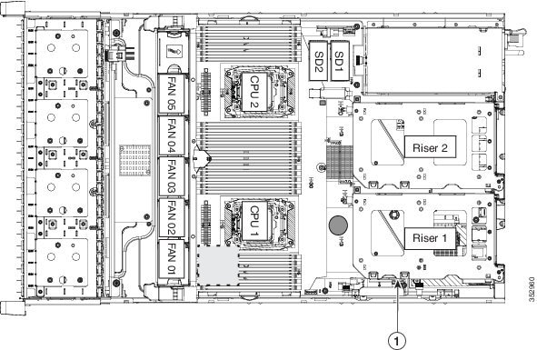
The server uses a SATA interposer board and cable to connect the embedded RAID (PCH SATA) controller on the motherboard to the drive backplane. See Figure 3-19 for the socket location.
Note![]() The SATA interposer board and embedded RAID can be used only with the SFF, 8-drive backplane version of the server. It does not operate with an expander. You cannot use the embedded RAID controller and a hardware RAID controller card at the same time.
The SATA interposer board and embedded RAID can be used only with the SFF, 8-drive backplane version of the server. It does not operate with an expander. You cannot use the embedded RAID controller and a hardware RAID controller card at the same time.
See Embedded SATA RAID Controller for more information about using the embedded RAID controller and options.
Step 1![]() Power off the server as described in the Shutting Down and Powering Off the Server.
Power off the server as described in the Shutting Down and Powering Off the Server.
Step 2![]() Slide the server out the front of the rack far enough so that you can remove the top cover. You might have to detach cables from the rear panel to provide clearance.
Slide the server out the front of the rack far enough so that you can remove the top cover. You might have to detach cables from the rear panel to provide clearance.
Step 3![]() Remove the top cover as described in Removing and Replacing the Server Top Cover.
Remove the top cover as described in Removing and Replacing the Server Top Cover.
Step 4![]() Remove the plastic air baffle that sits over the CPUs to gain access to the interposer cables.
Remove the plastic air baffle that sits over the CPUs to gain access to the interposer cables.
Step 5![]() Remove PCIe riser 1 from the server to provide clearance. See Replacing a PCIe Riser.
Remove PCIe riser 1 from the server to provide clearance. See Replacing a PCIe Riser.
Step 6![]() Remove any existing PCH SATA interposer board:
Remove any existing PCH SATA interposer board:
a.![]() Disconnect both cable connectors from the interposer board.
Disconnect both cable connectors from the interposer board.
b.![]() Lift straight up on the board to remove it from its motherboard socket.
Lift straight up on the board to remove it from its motherboard socket.
Step 7![]() Install a new interposer board and cables:
Install a new interposer board and cables:
Note![]() The required Y-cable and SATA interposer board are bundled as UCSC-IP-PCH-C240M4=.
The required Y-cable and SATA interposer board are bundled as UCSC-IP-PCH-C240M4=.
a.![]() Align the board with the socket, and then gently press down on both top corners to seat it evenly.
Align the board with the socket, and then gently press down on both top corners to seat it evenly.
b.![]() Connect the single mini-SAS HD cable connector to the single connector on the backplane.
Connect the single mini-SAS HD cable connector to the single connector on the backplane.
c.![]() Route the cables through the plastic clips on the chassis wall.
Route the cables through the plastic clips on the chassis wall.
d.![]() Connect PORT A and PORT B cable connectors to their corresponding connectors on the new interposer board.
Connect PORT A and PORT B cable connectors to their corresponding connectors on the new interposer board.
Step 8![]() Replace PCIe riser 1 to the server.
Replace PCIe riser 1 to the server.
Step 9![]() Replace the air baffle.
Replace the air baffle.
Step 10![]() Replace the top cover.
Replace the top cover.
Step 11![]() Replace the server in the rack, replace cables, and then power on the server by pressing the Power button.
Replace the server in the rack, replace cables, and then power on the server by pressing the Power button.
Figure 3-19 SATA Interposer Board Socket Location
|
|
|
Replacing a Cisco Modular RAID Controller Card
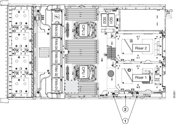
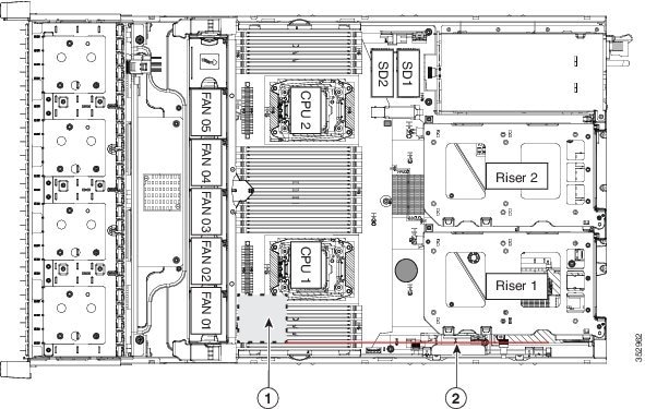
The server has an internal, dedicated PCIe slot on the motherboard for a Cisco modular RAID controller card (see Figure 3-20).
- Replacing a Modular RAID Controller Transportable Memory Module (TMM)
- Replacing the Supercap Power Module (RAID Backup Battery)
Note![]() You cannot use a hardware RAID controller card and the embedded RAID controller at the same time. See RAID Controller Considerations for details about RAID support.
You cannot use a hardware RAID controller card and the embedded RAID controller at the same time. See RAID Controller Considerations for details about RAID support.
RAID Card Firmware Compatibility
If the PCIe card that you are installing is a RAID controller card, firmware on the RAID controller must be verified for compatibility with the current Cisco IMC and BIOS versions that are installed on the server. If not compatible, upgrade or downgrade the RAID controller firmware accordingly using the Host Upgrade Utility (HUU) for your firmware release to bring it to a compatible level.
See the HUU guide for your Cisco IMC release for instructions on downloading and using the utility to bring server components to compatible levels: HUU Guides
Replacement Procedure
Step 1![]() Power off the server as described in Shutting Down and Powering Off the Server.
Power off the server as described in Shutting Down and Powering Off the Server.
Step 2![]() Slide the server out the front of the rack far enough so that you can remove the top cover. You might have to detach cables from the rear panel to provide clearance.
Slide the server out the front of the rack far enough so that you can remove the top cover. You might have to detach cables from the rear panel to provide clearance.
Step 3![]() Remove the top cover as described in Removing and Replacing the Server Top Cover.
Remove the top cover as described in Removing and Replacing the Server Top Cover.
Step 4![]() Remove an existing RAID controller card:
Remove an existing RAID controller card:
a.![]() Disconnect the data cable from the card. Depress the tab on the cable connector and pull.
Disconnect the data cable from the card. Depress the tab on the cable connector and pull.
b.![]() Disconnect the supercap power module cable from the transportable memory module (TMM), if present.
Disconnect the supercap power module cable from the transportable memory module (TMM), if present.
c.![]() Lift straight up on the metal bracket that holds the card. The bracket lifts off of two pegs on the chassis wall.
Lift straight up on the metal bracket that holds the card. The bracket lifts off of two pegs on the chassis wall.
d.![]() Loosen the two thumbscrews that hold the card to the metal bracket and then lift the card from the bracket.
Loosen the two thumbscrews that hold the card to the metal bracket and then lift the card from the bracket.
Step 5![]() Install a new RAID controller card:
Install a new RAID controller card:
a.![]() Set the new card on the metal bracket, aligned so that the thumbscrews on the card enter the threaded standoffs on the bracket. Tighten the thumbscrews to secure the card to the bracket.
Set the new card on the metal bracket, aligned so that the thumbscrews on the card enter the threaded standoffs on the bracket. Tighten the thumbscrews to secure the card to the bracket.
b.![]() Align the two slots on the back of the bracket with the two pegs on the chassis wall.
Align the two slots on the back of the bracket with the two pegs on the chassis wall.
The two slots on the bracket must slide down over the pegs at the same time that you push the card into the motherboard socket.
c.![]() Gently press down on both top corners of the metal bracket to seat the card into the socket on the motherboard.
Gently press down on both top corners of the metal bracket to seat the card into the socket on the motherboard.
d.![]() Connect the supercap power module cable to its connector on the TMM, if present.
Connect the supercap power module cable to its connector on the TMM, if present.
e.![]() Connect the single data cable to the card.
Connect the single data cable to the card.
Step 7![]() Replace the server in the rack, replace cables, and then power on the server by pressing the Power button.
Replace the server in the rack, replace cables, and then power on the server by pressing the Power button.
Figure 3-20 Modular RAID Controller Card Location
|
|
|
Replacing a Modular RAID Controller Transportable Memory Module (TMM)
The transportable memory module (TMM) that attaches to the modular RAID controller card can be installed or replaced after-factory.
- Replacing a Cisco Modular RAID Controller Card
- Replacing the Supercap Power Module (RAID Backup Battery)
Step 1![]() Power off the server as described in Shutting Down and Powering Off the Server.
Power off the server as described in Shutting Down and Powering Off the Server.
Step 2![]() Slide the server out the front of the rack far enough so that you can remove the top cover. You might have to detach cables from the rear panel to provide clearance.
Slide the server out the front of the rack far enough so that you can remove the top cover. You might have to detach cables from the rear panel to provide clearance.
Step 3![]() Remove the top cover as described in Removing and Replacing the Server Top Cover.
Remove the top cover as described in Removing and Replacing the Server Top Cover.
Step 4![]() Remove the modular RAID controller card from the server:
Remove the modular RAID controller card from the server:
a.![]() Lift straight up on the metal bracket that holds the card. The bracket lifts off of two pegs on the chassis wall (see Figure 3-20).
Lift straight up on the metal bracket that holds the card. The bracket lifts off of two pegs on the chassis wall (see Figure 3-20).
b.![]() Disconnect the supercap power module cable from the TMM that is attached to the card.
Disconnect the supercap power module cable from the TMM that is attached to the card.
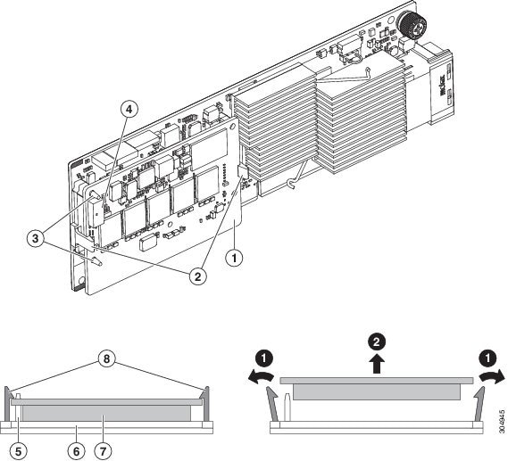
Step 5![]() Remove the TMM from the modular RAID controller card (see Figure 3-21):
Remove the TMM from the modular RAID controller card (see Figure 3-21):
a.![]() The plastic bracket on the card has a securing plastic clip at each end of the TMM. Gently spread each clip away from the TMM.
The plastic bracket on the card has a securing plastic clip at each end of the TMM. Gently spread each clip away from the TMM.
b.![]() Pull straight up on the TMM to lift it off the two plastic guide pegs and the socket on the card.
Pull straight up on the TMM to lift it off the two plastic guide pegs and the socket on the card.
Step 6![]() Install a TMM to the modular RAID controller card (see Figure 3-21):
Install a TMM to the modular RAID controller card (see Figure 3-21):
a.![]() Align the TMM over the bracket on the card. Align the connector on the underside of the TMM with the socket on the card. Align the two guide holes on the TMM over the two guide pegs on the card.
Align the TMM over the bracket on the card. Align the connector on the underside of the TMM with the socket on the card. Align the two guide holes on the TMM over the two guide pegs on the card.
b.![]() Gently lower the TMM so that the guide holes on the TMM go over the guide pegs on the card.
Gently lower the TMM so that the guide holes on the TMM go over the guide pegs on the card.
c.![]() Press down on the TMM until the plastic clips on the bracket close over each end of the TMM.
Press down on the TMM until the plastic clips on the bracket close over each end of the TMM.
d.![]() Press down on the TMM to fully seat its connector with the socket on the card.
Press down on the TMM to fully seat its connector with the socket on the card.
Step 7![]() Install the modular RAID controller card back into the server:
Install the modular RAID controller card back into the server:
Note![]() If this is a first-time installation of your TMM, you must also install a supercap power module (SCPM). The SCPM cable attaches to a connector on the TMM. See Replacing the Supercap Power Module (RAID Backup Battery).
If this is a first-time installation of your TMM, you must also install a supercap power module (SCPM). The SCPM cable attaches to a connector on the TMM. See Replacing the Supercap Power Module (RAID Backup Battery).
a.![]() Connect the cable from the supercap power module (RAID battery) to the connector on the TMM (see Figure 3-21).
Connect the cable from the supercap power module (RAID battery) to the connector on the TMM (see Figure 3-21).
b.![]() Align the two slots on the back of the RAID card bracket with the two pegs on the chassis wall.
Align the two slots on the back of the RAID card bracket with the two pegs on the chassis wall.
The two slots on the bracket must slide down over the pegs at the same time that you push the card into the motherboard socket.
c.![]() Gently press down on both top corners of the metal bracket to seat the card into the socket on the motherboard.
Gently press down on both top corners of the metal bracket to seat the card into the socket on the motherboard.
Figure 3-21 TMM on Modular RAID Controller Card
|
|
|
||
|
|
|
||
|
|
|
||
|
|
|
Replacing the Supercap Power Module (RAID Backup Battery)
This server supports installation of one supercap power module (SCPM). The unit mounts to a clip on the removable air baffle (see Figure 3-22). The SCPM requires that you have a transportable memory module (TMM) attached to your RAID controller card because the connector for the SCPM cable is on the TMM.
- Replacing a Cisco Modular RAID Controller Card
- Replacing a Modular RAID Controller Transportable Memory Module (TMM)
The SCPM provides approximately three years of backup for the disk write-back cache DRAM in the case of a sudden power loss by offloading the cache to the NAND flash.
Step 1![]() Power off the server as described in Shutting Down and Powering Off the Server.
Power off the server as described in Shutting Down and Powering Off the Server.
Step 2![]() Slide the server out the front of the rack far enough so that you can remove the top cover. You might have to detach cables from the rear panel to provide clearance.
Slide the server out the front of the rack far enough so that you can remove the top cover. You might have to detach cables from the rear panel to provide clearance.
Step 3![]() Remove the top cover as described in Removing and Replacing the Server Top Cover.
Remove the top cover as described in Removing and Replacing the Server Top Cover.
Step 4![]() Remove an existing SCPM:
Remove an existing SCPM:
a.![]() Disconnect the existing SCPM cable from the transportable memory module (TMM) that is attached to the modular RAID controller card.
Disconnect the existing SCPM cable from the transportable memory module (TMM) that is attached to the modular RAID controller card.
b.![]() Pull back the plastic clip that closes over the SCPM slightly, and then slide the SCPM free of the clips on the air baffle mounting point (see Figure 3-22).
Pull back the plastic clip that closes over the SCPM slightly, and then slide the SCPM free of the clips on the air baffle mounting point (see Figure 3-22).
a.![]() Slide the new backup unit into the holder on the air baffle mounting point until the clip clicks over the top edge of the SCPM.
Slide the new backup unit into the holder on the air baffle mounting point until the clip clicks over the top edge of the SCPM.
b.![]() Connect the cable from the SCPM to the TMM that is attached to the modular RAID controller card.
Connect the cable from the SCPM to the TMM that is attached to the modular RAID controller card.
Note![]() Put the cable through the opening on the rear of the air baffle (rather than over the air baffle) to keep the cable from interfering with the top cover of the server.
Put the cable through the opening on the rear of the air baffle (rather than over the air baffle) to keep the cable from interfering with the top cover of the server.
Step 7![]() Replace the server in the rack, replace cables, and then power on the server by pressing the Power button.
Replace the server in the rack, replace cables, and then power on the server by pressing the Power button.
Figure 3-22 SCPM (RAID Backup Unit) Mounting Point and Cable Path
|
|
SCPM mounting point on removable air baffle (air baffle not shown) |
|
Replacing a Software RAID 5 Key Module
The server has a two-pin header on the motherboard for a RAID 5 key module. This module upgrades the embedded SATA RAID controller options (see Embedded SATA RAID Controller).
Step 1![]() Power off the server as described in Shutting Down and Powering Off the Server.
Power off the server as described in Shutting Down and Powering Off the Server.
Step 2![]() Slide the server out the front of the rack far enough so that you can remove the top cover. You might have to detach cables from the rear panel to provide clearance.
Slide the server out the front of the rack far enough so that you can remove the top cover. You might have to detach cables from the rear panel to provide clearance.
Step 3![]() Remove the top cover as described in Removing and Replacing the Server Top Cover.
Remove the top cover as described in Removing and Replacing the Server Top Cover.
Step 4![]() Remove any existing software RAID key module:
Remove any existing software RAID key module:
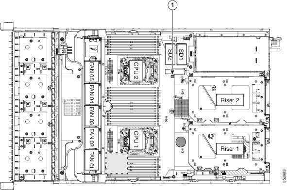
a.![]() Locate the module on the motherboard (see Figure 3-23).
Locate the module on the motherboard (see Figure 3-23).
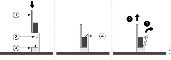
b.![]() Hold the retention clips on the header open while you grasp the RAID key board and pull straight up (see Figure 3-24).
Hold the retention clips on the header open while you grasp the RAID key board and pull straight up (see Figure 3-24).
Figure 3-23 RAID 5 Key Header Location on Motherboard
|
|
|
Step 5![]() Install a new software RAID key module:
Install a new software RAID key module:
a.![]() Align the module with the pins in the motherboard header.
Align the module with the pins in the motherboard header.
b.![]() Gently press down on the module until it is seated and the retention clip locks over the module (see Figure 3-24).
Gently press down on the module until it is seated and the retention clip locks over the module (see Figure 3-24).
Figure 3-24 Software RAID 5 Key Module Retention Clip
|
|
|
||
|
|
|
Replacing the Motherboard RTC Battery
Warning![]() There is danger of explosion if the battery is replaced incorrectly. Replace the battery only with the same or equivalent type recommended by the manufacturer. Dispose of used batteries according to the manufacturer’s instructions. [Statement 1015]
There is danger of explosion if the battery is replaced incorrectly. Replace the battery only with the same or equivalent type recommended by the manufacturer. Dispose of used batteries according to the manufacturer’s instructions. [Statement 1015]
The real-time clock (RTC) battery retains system settings when the server is disconnected from power. The battery type is CR2032. Cisco supports the industry-standard CR2032 battery, which can be purchased from most electronic stores.
Step 1![]() Power off the server as described in Shutting Down and Powering Off the Server.
Power off the server as described in Shutting Down and Powering Off the Server.
Step 2![]() Slide the server out the front of the rack far enough so that you can remove the top cover. You might have to detach cables from the rear panel to provide clearance.
Slide the server out the front of the rack far enough so that you can remove the top cover. You might have to detach cables from the rear panel to provide clearance.
Step 3![]() Remove the top cover as described in Removing and Replacing the Server Top Cover.
Remove the top cover as described in Removing and Replacing the Server Top Cover.
Step 4![]() Remove the battery from its holder on the motherboard (see Figure 3-25):
Remove the battery from its holder on the motherboard (see Figure 3-25):
a.![]() Use a small screwdriver or pointed object to press inward on the battery at the prying point (see Figure 3-25).
Use a small screwdriver or pointed object to press inward on the battery at the prying point (see Figure 3-25).
b.![]() Lift up on the battery and remove it from the holder.
Lift up on the battery and remove it from the holder.
Step 5![]() Install an RTC battery. Insert the battery into its holder and press down until it clicks in place.
Install an RTC battery. Insert the battery into its holder and press down until it clicks in place.
Note![]() The positive side of the battery marked “3V+” should face upward.
The positive side of the battery marked “3V+” should face upward.
Step 7![]() Replace the server in the rack, replace cables, and power on the server by pressing the Power button.
Replace the server in the rack, replace cables, and power on the server by pressing the Power button.
Figure 3-25 RTC Battery Location and Prying Point
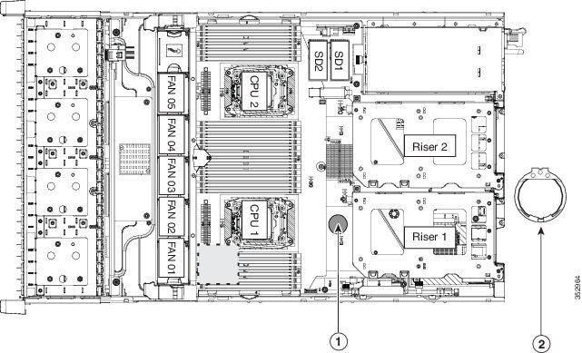
|
|
|
Replacing an Internal SD Card
The server has two internal SD card bays on the motherboard.
Dual SD cards are supported. RAID 1 support can be configured through the Cisco IMC interface.
Step 1![]() Power off the server as described in Shutting Down and Powering Off the Server.
Power off the server as described in Shutting Down and Powering Off the Server.
Step 2![]() Slide the server out the front of the rack far enough so that you can remove the top cover. You might have to detach cables from the rear panel to provide clearance.
Slide the server out the front of the rack far enough so that you can remove the top cover. You might have to detach cables from the rear panel to provide clearance.
Step 3![]() Remove the top cover as described in Removing and Replacing the Server Top Cover.
Remove the top cover as described in Removing and Replacing the Server Top Cover.
Step 4![]() Remove an SD card (see Figure 3-26).
Remove an SD card (see Figure 3-26).
a.![]() Push on the top of the SD card, and then release it to allow it to spring out from the slot.
Push on the top of the SD card, and then release it to allow it to spring out from the slot.
b.![]() Remove the SD card from the slot.
Remove the SD card from the slot.
a.![]() Insert the SD card into the slot with the label side facing up.
Insert the SD card into the slot with the label side facing up.
b.![]() Press on the top of the card until it clicks in the slot and stays in place.
Press on the top of the card until it clicks in the slot and stays in place.
Step 7![]() Replace the server in the rack, replace cables, and then power on the server by pressing the Power button.
Replace the server in the rack, replace cables, and then power on the server by pressing the Power button.
Figure 3-26 SD Card Bay Location and Numbering on the Motherboard
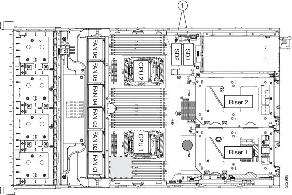
|
|
|
Enabling or Disabling the Internal USB Port
The factory default is for all USB ports on the server to be enabled. However, the internal USB port can be enabled or disabled in the server BIOS. See Figure 3-5 for the location of the internal USB 3.0 slot on the motherboard.
Step 1![]() Enter the BIOS Setup Utility by pressing the F2 key when prompted during bootup.
Enter the BIOS Setup Utility by pressing the F2 key when prompted during bootup.
Step 2![]() Navigate to the Advanced tab.
Navigate to the Advanced tab.
Step 3![]() On the Advanced tab, select USB Configuration.
On the Advanced tab, select USB Configuration.
Step 4![]() On the USB Configuration page, choose USB Ports Configuration.
On the USB Configuration page, choose USB Ports Configuration.
Step 5![]() Scroll to USB Port: Internal, press Enter, and then choose either Enabled or Disabled from the dialog box.
Scroll to USB Port: Internal, press Enter, and then choose either Enabled or Disabled from the dialog box.
Step 6![]() Press F10 to save and exit the utility.
Press F10 to save and exit the utility.
Replacing a PCIe Riser
The server contains two toolless PCIe risers for horizontal installation of PCIe cards. See Replacing a PCIe Card for the specifications of the PCIe slots on the risers.
Step 1![]() Power off the server as described in Shutting Down and Powering Off the Server.
Power off the server as described in Shutting Down and Powering Off the Server.
Step 2![]() Slide the server out the front of the rack far enough so that you can remove the top cover. You might have to detach cables from the rear panel to provide clearance.
Slide the server out the front of the rack far enough so that you can remove the top cover. You might have to detach cables from the rear panel to provide clearance.
Step 3![]() Remove the top cover as described in Removing and Replacing the Server Top Cover.
Remove the top cover as described in Removing and Replacing the Server Top Cover.
Step 4![]() Remove the PCIe riser that you are replacing (see Figure 3-27):
Remove the PCIe riser that you are replacing (see Figure 3-27):
a.![]() Grasp the top of the riser and lift straight up on both ends to disengage its circuit board from the socket on the motherboard. Set the riser on an antistatic mat.
Grasp the top of the riser and lift straight up on both ends to disengage its circuit board from the socket on the motherboard. Set the riser on an antistatic mat.
b.![]() If the riser has a card installed, remove the card from the riser. See Replacing a PCIe Card.
If the riser has a card installed, remove the card from the riser. See Replacing a PCIe Card.
Step 5![]() Install a new PCIe riser:
Install a new PCIe riser:
a.![]() If you removed a card from the old PCIe riser, install the card to the new riser (see Replacing a PCIe Card).
If you removed a card from the old PCIe riser, install the card to the new riser (see Replacing a PCIe Card).
b.![]() Position the PCIe riser over its socket on the motherboard and over its alignment slots in the chassis (see Figure 3-27). There are also two alignment pegs on the motherboard for each riser.
Position the PCIe riser over its socket on the motherboard and over its alignment slots in the chassis (see Figure 3-27). There are also two alignment pegs on the motherboard for each riser.
Note![]() The PCIe risers are not interchangeable. If you plug a PCIe riser into the wrong socket, the server will not boot. Riser 1 must plug into the motherboard socket labeled “RISER1.” Riser 2 must plug into the motherboard socket labeled “RISER2.”
The PCIe risers are not interchangeable. If you plug a PCIe riser into the wrong socket, the server will not boot. Riser 1 must plug into the motherboard socket labeled “RISER1.” Riser 2 must plug into the motherboard socket labeled “RISER2.”
c.![]() Carefully push down on both ends of the PCIe riser to fully engage its circuit board connector with the socket on the motherboard.
Carefully push down on both ends of the PCIe riser to fully engage its circuit board connector with the socket on the motherboard.
Step 7![]() Replace the server in the rack, replace cables, and then power on the server by pressing the Power button.
Replace the server in the rack, replace cables, and then power on the server by pressing the Power button.
Figure 3-27 PCIe Riser Alignment Features
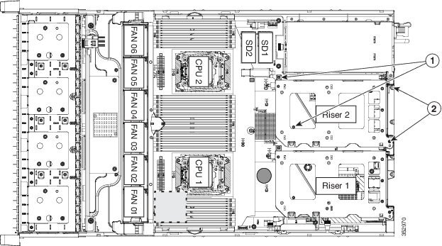
|
|
|
Replacing a PCIe Card
PCIe Slots
The server contains two toolless PCIe risers for horizontal installation of PCIe cards (see Figure 3-28).
–![]() Version 1: Two slots (PCIE 1 and 2) and a blank to accommodate a GPU card in slot 2. See Table 3-8 .
Version 1: Two slots (PCIE 1 and 2) and a blank to accommodate a GPU card in slot 2. See Table 3-8 .
–![]() Version 2: Three slots (PCIE 1, 2, and 3). See Table 3-9 .
Version 2: Three slots (PCIE 1, 2, and 3). See Table 3-9 .
–![]() Version 3: Two slots (PCIE 1 and 2) and two SATA boot-drive sockets. See Table 3-10 .
Version 3: Two slots (PCIE 1 and 2) and two SATA boot-drive sockets. See Table 3-10 .
- Riser 2 contains slots PCIE 4, 5, and 6. See Table 3-11 .
Figure 3-28 Rear Panel, Showing PCIe Slots
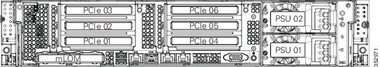
|
|
Lane Width |
|
|
|
|
|---|---|---|---|---|---|
Yes4 |
|||||
|
|
Lane Width |
|
|
|
|
|---|---|---|---|---|---|
|
5.GPU cards are not supported in this riser 1B version. There is no GPU power connector in this version. Use riser version 1A or 1C for GPU cards. |
|
|
Lane Width |
|
|
|
|
|---|---|---|---|---|---|
|
|
Lane Width |
|
|
|
|
|---|---|---|---|---|---|
Yes6 |
|||||
|
6.NCSI is supported in only one slot at a time in this riser version. If a GPU card is present in slot 5, NCSI support automatically moves to slot 4. |
Replacing a PCIe Card
The Technical Specifications Sheets for all versions of this server, which include supported component part numbers, are at Cisco UCS Servers Technical Specifications Sheets.
Note![]() If you are installing a Cisco UCS Virtual Interface Card, there are prerequisite considerations. See Special Considerations for Cisco UCS Virtual Interface Cards.
If you are installing a Cisco UCS Virtual Interface Card, there are prerequisite considerations. See Special Considerations for Cisco UCS Virtual Interface Cards.
Note![]() If you are installing a Fusion ioMemory3 card, there are prerequisite considerations. See Special Considerations for Cisco UCS Fusion ioMemory3 Storage Accelerator Cards.
If you are installing a Fusion ioMemory3 card, there are prerequisite considerations. See Special Considerations for Cisco UCS Fusion ioMemory3 Storage Accelerator Cards.
Note![]() If you are installing a RAID controller card, see RAID Controller Considerations for more information about supported cards and cabling.
If you are installing a RAID controller card, see RAID Controller Considerations for more information about supported cards and cabling.
Step 1![]() Shut down and power off the server as described in Shutting Down and Powering Off the Server.
Shut down and power off the server as described in Shutting Down and Powering Off the Server.
Step 2![]() Slide the server out the front of the rack far enough so that you can remove the top cover. You might have to detach cables from the rear panel to provide clearance.
Slide the server out the front of the rack far enough so that you can remove the top cover. You might have to detach cables from the rear panel to provide clearance.
Step 3![]() Remove the top cover as described in Removing and Replacing the Server Top Cover.
Remove the top cover as described in Removing and Replacing the Server Top Cover.
Step 4![]() Remove a PCIe card (or a blanking panel) from the PCIe riser:
Remove a PCIe card (or a blanking panel) from the PCIe riser:
a.![]() Lift straight up on both ends of the riser to disengage its circuit board from the socket on the motherboard. Set the riser on an antistatic mat.
Lift straight up on both ends of the riser to disengage its circuit board from the socket on the motherboard. Set the riser on an antistatic mat.
b.![]() On the bottom of the riser, loosen the single thumbscrew that holds the securing plate (see Figure 3-29).
On the bottom of the riser, loosen the single thumbscrew that holds the securing plate (see Figure 3-29).
c.![]() Swing open the securing plate and remove it from the riser to provide access.
Swing open the securing plate and remove it from the riser to provide access.
d.![]() Swing open the card-tab retainer that secures the back-panel tab of the card (see Figure 3-29).
Swing open the card-tab retainer that secures the back-panel tab of the card (see Figure 3-29).
e.![]() Pull evenly on both ends of the PCIe card to disengage it from the socket on the PCIe riser (or remove a blanking panel) and then set the card aside.
Pull evenly on both ends of the PCIe card to disengage it from the socket on the PCIe riser (or remove a blanking panel) and then set the card aside.
a.![]() Align the new PCIe card with the empty socket on the PCIe riser.
Align the new PCIe card with the empty socket on the PCIe riser.
b.![]() Push down evenly on both ends of the card until it is fully seated in the socket.
Push down evenly on both ends of the card until it is fully seated in the socket.
Ensure that the card rear panel tab sits flat against the PCIe riser rear panel opening.
c.![]() Close the card-tab retainer (see Figure 3-29).
Close the card-tab retainer (see Figure 3-29).
d.![]() Return the securing plate to the riser. Insert the two hinge-tabs into the two slots on the riser, and then swing the securing plate closed.
Return the securing plate to the riser. Insert the two hinge-tabs into the two slots on the riser, and then swing the securing plate closed.
e.![]() Tighten the single thumbscrew on the bottom of the securing plate.
Tighten the single thumbscrew on the bottom of the securing plate.
f.![]() Position the PCIe riser over its socket on the motherboard and over its alignment features in the chassis (see Figure 3-27).
Position the PCIe riser over its socket on the motherboard and over its alignment features in the chassis (see Figure 3-27).
g.![]() Carefully push down on both ends of the PCIe riser to fully engage its circuit board connector with the socket on the motherboard.
Carefully push down on both ends of the PCIe riser to fully engage its circuit board connector with the socket on the motherboard.
Step 7![]() Replace the server in the rack, replace cables, and then power on the server by pressing the Power button.
Replace the server in the rack, replace cables, and then power on the server by pressing the Power button.
Step 8![]() If you replaced a RAID controller card, continue with Restoring RAID Configuration After Replacing a RAID Controller.
If you replaced a RAID controller card, continue with Restoring RAID Configuration After Replacing a RAID Controller.
Figure 3-29 PCIe Riser Securing Features (Three-Slot Riser Shown)
|
|
|
||
|
|
Securing plate thumbscrew (knob not visible on underside of plate) |
|
Special Considerations for Cisco UCS Virtual Interface Cards
Table 3-12 describes the requirements for the supported Cisco UCS virtual interface cards (VICs).
The server can support up to two PCIe-style VICs plus one mLOM-style VIC.
Note![]() If you use the Cisco Card NIC mode, you must also make a VIC Slot setting that matches where your VIC is installed. The options are Riser1, Riser2, or Flex-LOM. See NIC Modes and NIC Redundancy Settings.
If you use the Cisco Card NIC mode, you must also make a VIC Slot setting that matches where your VIC is installed. The options are Riser1, Riser2, or Flex-LOM. See NIC Modes and NIC Redundancy Settings.
If you want to use the Cisco UCS VIC card for Cisco UCS Manager integration, also see the Cisco UCS C-Series Server Integration with UCS Manager Guides for details about supported configurations, cabling, and other requirements.
|
|
|
|
|
|
|
|
|---|---|---|---|---|---|---|
|
|
See footnote7 |
See footnote.8 |
||||
|
|
See footnote.9 |
|||||
|
|
||||||
|
|
||||||
|
|
||||||
|
|
Note![]() The Cisco UCS VIC 1227 (UCSC-MLOM-CSC-02) is not compatible to use in Cisco Card NIC mode with a certain Cisco SFP+ module. Do not use a Cisco SFP+ module part number 37-0961-01 that has a serial number in the range MOC1238xxxx to MOC1309xxxx. If you use the Cisco UCS VIC 1227 in Cisco Card NIC mode, use a different part number Cisco SFP+ module, or you can use this part number 37-0961-01 if the serial number is not included in the range above. See the data sheet for this adapter for other supported SFP+ modules: Cisco UCS VIC 1227 Data Sheet
The Cisco UCS VIC 1227 (UCSC-MLOM-CSC-02) is not compatible to use in Cisco Card NIC mode with a certain Cisco SFP+ module. Do not use a Cisco SFP+ module part number 37-0961-01 that has a serial number in the range MOC1238xxxx to MOC1309xxxx. If you use the Cisco UCS VIC 1227 in Cisco Card NIC mode, use a different part number Cisco SFP+ module, or you can use this part number 37-0961-01 if the serial number is not included in the range above. See the data sheet for this adapter for other supported SFP+ modules: Cisco UCS VIC 1227 Data Sheet
Special Considerations for Cisco UCS Fusion ioMemory3 Storage Accelerator Cards
Table 3-13 describes the requirements for the supported Cisco UCS Fusion ioMemory3 cards.
|
|
|
|
|
|
|---|---|---|---|---|
|
|
611 |
|||
|
|
Half height12 |
|||
|
|
||||
|
|
||||
|
|
||||
|
|
Installing Multiple PCIe Cards and Resolving Limited Resources
When a large number of PCIe add-on cards are installed in the server, the system might run out of the following resources required for PCIe devices:
The topics in this section provide guidelines for resolving the issues related to these limited resources:
Resolving Insufficient Memory Space to Execute Option ROMs
The system has very limited memory to execute PCIe legacy option ROMs, so when a large number of PCIe add-on cards are installed in the server, the system BIOS might not able to execute all of the option ROMs. The system BIOS loads and executes the option ROMs in the order that the PCIe cards are enumerated (slot 1, slot 2, slot 3, and so on).
If the system BIOS does not have sufficient memory space to load any PCIe option ROM, it skips loading that option ROM, reports a system event log (SEL) event to the Cisco IMC controller and reports the following error in the Error Manager page of the BIOS Setup utility:
To resolve this issue, disable the Option ROMs that are not needed for system booting. The BIOS Setup Utility provides the setup options to enable or disable the Option ROMs at the PCIe slot level for the PCIe expansion slots and at the port level for the onboard NICs. These options can be found in the BIOS Setup Utility Advanced > PCI Configuration page.
If the server is configured to boot primarily from RAID storage, make sure that the option ROMs for the slots where your RAID controllers installed are enabled in the BIOS, depending on your RAID controller configuration.
If the RAID controller does not appear in the system boot order even with the option ROMs for those slots are enabled, the RAID controller option ROM might not have sufficient memory space to execute. In that case, disable other option ROMs that are not needed for the system configuration to free up some memory space for the RAID controller option ROM.
If the system is configured to primarily perform PXE boot from onboard NICs, make sure that the option ROMs for the onboard NICs to be booted from are enabled in the BIOS Setup Utility. Disable other option ROMs that are not needed to create sufficient memory space for the onboard NICs.
Resolving Insufficient 16-Bit I/O Space
The system has only 64 KB of legacy 16-bit I/O resources available. This 64 KB of I/O space is divided between the CPUs in the system because the PCIe controller is integrated into the CPUs. This server BIOS has the capability to dynamically detect the 16-bit I/O resource requirement for each CPU and then balance the 16-bit I/O resource allocation between the CPUs during the PCI bus enumeration phase of the BIOS POST.
When a large number of PCIe cards are installed in the system, the system BIOS might not have sufficient I/O space for some PCIe devices. If the system BIOS is not able to allocate the required I/O resources for any PCIe devices, the following symptoms have been observed:
- The system might get stuck in an infinite reset loop.
- The BIOS might appear to hang while initializing PCIe devices.
- The PCIe option ROMs might take excessive time to complete, which appears to lock up the system.
- PCIe boot devices might not be accessible from the BIOS.
- PCIe option ROMs might report initialization errors. These errors are seen before the BIOS passes control to the operating system.
- The keyboard might not work.
To work around this problem, rebalance the 16-bit I/O load using the following methods:
1.![]() Physically remove any unused PCIe cards.
Physically remove any unused PCIe cards.
2.![]() If the system has one or more Cisco virtual interface cards (VICs) installed, disable the PXE boot on the VICs that are not required for the system boot configuration by using the Network Adapters page in Cisco IMC Web UI to free up some 16-bit I/O resources. Each VIC uses a minimum 16 KB of 16-bit I/O resource, so disabling PXE boot on Cisco VICs would free up some 16-bit I/O resources that can be used for other PCIe cards that are installed in the system.
If the system has one or more Cisco virtual interface cards (VICs) installed, disable the PXE boot on the VICs that are not required for the system boot configuration by using the Network Adapters page in Cisco IMC Web UI to free up some 16-bit I/O resources. Each VIC uses a minimum 16 KB of 16-bit I/O resource, so disabling PXE boot on Cisco VICs would free up some 16-bit I/O resources that can be used for other PCIe cards that are installed in the system.
Installing an NVIDIA GPU Card
Replacing Internal SATA Boot Drives
Note![]() SATA boot drives are supported only in the SFF 24-drive and LFF 12-drive versions of the server.
SATA boot drives are supported only in the SFF 24-drive and LFF 12-drive versions of the server.
The SFF 24-drive and LFF 12-drive versions of the server can support two solid-state SATA boot drives, but only when the PCIe riser 1C option is installed (UCSC-PCI-1C-240M4). This version of riser 1 has two SATA boot drive connectors in place of slot 3.
Note![]() The two internal SATA boot drives can be mirrored in a RAID 1 configuration when managed by the embedded RAID controller or in advanced host controller interface (AHCI) mode through your Windows or Linux operating system. The SATA mode must be enabled and selected in the BIOS, as described in Enabling the Embedded RAID Controller in the BIOS.
The two internal SATA boot drives can be mirrored in a RAID 1 configuration when managed by the embedded RAID controller or in advanced host controller interface (AHCI) mode through your Windows or Linux operating system. The SATA mode must be enabled and selected in the BIOS, as described in Enabling the Embedded RAID Controller in the BIOS.
Replacing an Internal SATA Boot Drive
Step 1![]() Shut down and power off the server as described in Shutting Down and Powering Off the Server.
Shut down and power off the server as described in Shutting Down and Powering Off the Server.
Step 2![]() Slide the server out the front of the rack far enough so that you can remove the top cover. You might have to detach cables from the rear panel to provide clearance.
Slide the server out the front of the rack far enough so that you can remove the top cover. You might have to detach cables from the rear panel to provide clearance.
Step 3![]() Remove the top cover as described in Removing and Replacing the Server Top Cover.
Remove the top cover as described in Removing and Replacing the Server Top Cover.
Step 4![]() Remove PCIe riser 1C from the server:
Remove PCIe riser 1C from the server:
a.![]() Lift straight up on both ends of the riser to disengage its circuit board from the socket on the motherboard. Set the riser on an antistatic mat.
Lift straight up on both ends of the riser to disengage its circuit board from the socket on the motherboard. Set the riser on an antistatic mat.
b.![]() On the bottom of the riser, loosen the single thumbscrew that holds the securing plate. See Figure 3-29.
On the bottom of the riser, loosen the single thumbscrew that holds the securing plate. See Figure 3-29.
c.![]() Swing open the securing plate and remove it from the riser to provide access.
Swing open the securing plate and remove it from the riser to provide access.
Step 5![]() Remove an existing SATA boot drive from PCIe riser 1C.
Remove an existing SATA boot drive from PCIe riser 1C.
Grasp the carrier-tabs on each side of the boot drive and pinch them together as you pull the boot drive from its cage and the socket on the PCIe riser.
Step 6![]() Install a new SATA boot drive to PCIe riser 1C.
Install a new SATA boot drive to PCIe riser 1C.
a.![]() Grasp the two carrier-tabs on either side of the boot drive and pinch them together as you insert the drive into the cage on the riser.
Grasp the two carrier-tabs on either side of the boot drive and pinch them together as you insert the drive into the cage on the riser.
b.![]() Push the drive straight into the cage to engage it with the socket on the riser. Stop when the carrier-tabs click and lock into place on the cage.
Push the drive straight into the cage to engage it with the socket on the riser. Stop when the carrier-tabs click and lock into place on the cage.
Step 7![]() Return PCIe riser 1C to the server:
Return PCIe riser 1C to the server:
a.![]() Return the securing plate to the riser. Insert the two hinge-tabs into the two slots on the riser, and then swing the securing plate closed.
Return the securing plate to the riser. Insert the two hinge-tabs into the two slots on the riser, and then swing the securing plate closed.
b.![]() Tighten the single thumbscrew that holds the securing plate.
Tighten the single thumbscrew that holds the securing plate.
c.![]() Position the PCIe riser over its socket on the motherboard and over its alignment features in the chassis (see Figure 3-27).
Position the PCIe riser over its socket on the motherboard and over its alignment features in the chassis (see Figure 3-27).
d.![]() Carefully push down on both ends of the PCIe riser to fully engage its circuit board connector with the socket on the motherboard.
Carefully push down on both ends of the PCIe riser to fully engage its circuit board connector with the socket on the motherboard.
Step 9![]() Replace the server in the rack, replace cables, and then power on the server by pressing the Power button.
Replace the server in the rack, replace cables, and then power on the server by pressing the Power button.
Step 10![]() Set the boot order for these SATA boot drives in the server BIOS as desired:
Set the boot order for these SATA boot drives in the server BIOS as desired:
a.![]() Boot the server and press F2 when prompted to enter the BIOS Setup Utility.
Boot the server and press F2 when prompted to enter the BIOS Setup Utility.
b.![]() Select the Boot Options tab.
Select the Boot Options tab.
c.![]() Set the boot order for your SATA boot drives.
Set the boot order for your SATA boot drives.
d.![]() Press F10 to exit the utility and save your changes.
Press F10 to exit the utility and save your changes.
Installing a Trusted Platform Module (TPM)
The trusted platform module (TPM) is a small circuit board that connects to a motherboard socket and is secured by a one-way screw.
TPM 2.0 Considerations
Trusted platform module (TPM) version 2.0 is supported on Intel v3- or Intel v4-based platforms.
If there is an existing TPM 1.2 installed in the server, you cannot upgrade to TPM 2.0.
If there is no existing TPM in the server, you can install TPM 2.0. You must first upgrade to Intel v4 code, regardless of whether the installed CPU is Intel v3 or v4. TPM 2.0 requires Intel v4 code or later.
Note![]() If the TPM 2.0 becomes unresponsive, reboot the server.
If the TPM 2.0 becomes unresponsive, reboot the server.
|
|
|
|
|
|---|---|---|---|
Installing the TPM Hardware
This section contains the following procedures, which must be followed in this order when installing and enabling a TPM:
1.![]() Installing the TPM Hardware
Installing the TPM Hardware
2.![]() Enabling TPM Support in the BIOS
Enabling TPM Support in the BIOS
3.![]() Enabling the Intel TXT Feature in the BIOS
Enabling the Intel TXT Feature in the BIOS
Note![]() For security purposes, the TPM is installed with a one-way screw. It cannot be removed with a standard screwdriver.
For security purposes, the TPM is installed with a one-way screw. It cannot be removed with a standard screwdriver.
Step 1![]() Prepare the server for component installation:
Prepare the server for component installation:
Step 2![]() Power off the server as described in Shutting Down and Powering Off the Server.
Power off the server as described in Shutting Down and Powering Off the Server.
Step 3![]() Slide the server out the front of the rack far enough so that you can remove the top cover. You might have to detach cables from the rear panel to provide clearance.
Slide the server out the front of the rack far enough so that you can remove the top cover. You might have to detach cables from the rear panel to provide clearance.
Step 4![]() Remove the top cover as described in Removing and Replacing the Server Top Cover.
Remove the top cover as described in Removing and Replacing the Server Top Cover.
Step 5![]() Remove PCIe riser 2 to provide clearance. See Replacing a PCIe Riser for instructions.
Remove PCIe riser 2 to provide clearance. See Replacing a PCIe Riser for instructions.
a.![]() Locate the TPM socket on the motherboard, as shown in Figure 3-30.
Locate the TPM socket on the motherboard, as shown in Figure 3-30.
b.![]() Align the connector that is on the bottom of the TPM circuit board with the motherboard TPM socket. Align the screw hole and standoff on the TPM board with the screw hole that is adjacent to the TPM socket.
Align the connector that is on the bottom of the TPM circuit board with the motherboard TPM socket. Align the screw hole and standoff on the TPM board with the screw hole that is adjacent to the TPM socket.
c.![]() Push down evenly on the TPM to seat it in the motherboard socket.
Push down evenly on the TPM to seat it in the motherboard socket.
d.![]() Install the single one-way screw that secures the TPM to the motherboard.
Install the single one-way screw that secures the TPM to the motherboard.
Step 7![]() Replace PCIe riser 2 to the server. See Replacing a PCIe Riser for instructions.
Replace PCIe riser 2 to the server. See Replacing a PCIe Riser for instructions.
Step 9![]() Replace the server in the rack, replace cables, and then power on the server by pressing the Power button.
Replace the server in the rack, replace cables, and then power on the server by pressing the Power button.
Step 10![]() Continue with Enabling TPM Support in the BIOS.
Continue with Enabling TPM Support in the BIOS.
Figure 3-30 TPM Socket Location on Motherboard
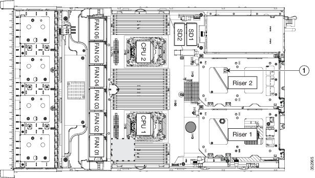
|
|
|
Enabling TPM Support in the BIOS
Note![]() After hardware installation, you must enable TPM support in the BIOS.
After hardware installation, you must enable TPM support in the BIOS.
Note![]() You must set a BIOS Administrator password before performing this procedure. To set this password, press the F2 key when prompted during system boot to enter the BIOS Setup utility. Then navigate to Security > Set Administrator Password and enter the new password twice as prompted.
You must set a BIOS Administrator password before performing this procedure. To set this password, press the F2 key when prompted during system boot to enter the BIOS Setup utility. Then navigate to Security > Set Administrator Password and enter the new password twice as prompted.
a.![]() Watch during bootup for the F2 prompt, and then press F2 to enter BIOS setup.
Watch during bootup for the F2 prompt, and then press F2 to enter BIOS setup.
b.![]() Log in to the BIOS Setup Utility with your BIOS Administrator password.
Log in to the BIOS Setup Utility with your BIOS Administrator password.
c.![]() On the BIOS Setup Utility window, choose the Advanced tab.
On the BIOS Setup Utility window, choose the Advanced tab.
d.![]() Choose Trusted Computing to open the TPM Security Device Configuration window.
Choose Trusted Computing to open the TPM Security Device Configuration window.
e.![]() Change TPM SUPPORT to Enabled.
Change TPM SUPPORT to Enabled.
f.![]() Press F10 to save your settings and reboot the server.
Press F10 to save your settings and reboot the server.
Step 2![]() Verify that TPM support is now enabled:
Verify that TPM support is now enabled:
a.![]() Watch during bootup for the F2 prompt, and then press F2 to enter BIOS setup.
Watch during bootup for the F2 prompt, and then press F2 to enter BIOS setup.
b.![]() Log into the BIOS Setup utility with your BIOS Administrator password.
Log into the BIOS Setup utility with your BIOS Administrator password.
d.![]() Choose Trusted Computing to open the TPM Security Device Configuration window.
Choose Trusted Computing to open the TPM Security Device Configuration window.
e.![]() Verify that TPM SUPPORT and TPM State are Enabled.
Verify that TPM SUPPORT and TPM State are Enabled.
Step 3![]() Continue with Enabling the Intel TXT Feature in the BIOS.
Continue with Enabling the Intel TXT Feature in the BIOS.
Enabling the Intel TXT Feature in the BIOS
Intel Trusted Execution Technology (TXT) provides greater protection for information that is used and stored on the business server. A key aspect of that protection is the provision of an isolated execution environment and associated sections of memory where operations can be conducted on sensitive data, invisibly to the rest of the system. Intel TXT provides for a sealed portion of storage where sensitive data such as encryption keys can be kept, helping to shield them from being compromised during an attack by malicious code.
Note![]() You must be logged in as the BIOS administrator to perform this procedure. If you have not done so already, set a BIOS administrator password on the Security tab of the BIOS Setup utility.
You must be logged in as the BIOS administrator to perform this procedure. If you have not done so already, set a BIOS administrator password on the Security tab of the BIOS Setup utility.
Step 1![]() Reboot the server and watch for the prompt to press F2.
Reboot the server and watch for the prompt to press F2.
Step 2![]() When prompted, press F2 to enter the BIOS Setup utility.
When prompted, press F2 to enter the BIOS Setup utility.
Step 3![]() Verify that the prerequisite BIOS values are enabled:
Verify that the prerequisite BIOS values are enabled:
b.![]() Choose Intel TXT(LT-SX) Configuration to open the Intel TXT(LT-SX) Hardware Support window.
Choose Intel TXT(LT-SX) Configuration to open the Intel TXT(LT-SX) Hardware Support window.
c.![]() Verify that the following items are listed as Enabled:
Verify that the following items are listed as Enabled:
–![]() VT-d Support (default is Enabled)
VT-d Support (default is Enabled)
–![]() VT Support (default is Enabled)
VT Support (default is Enabled)
- If VT-d Support and VT Support are already enabled, skip to Step 4.
- If VT-d Support and VT Support are not enabled, continue with the next steps to enable them.
d.![]() Press Escape to return to the BIOS Setup utility Advanced tab.
Press Escape to return to the BIOS Setup utility Advanced tab.
e.![]() On the Advanced tab, choose Processor Configuration to open the Processor Configuration window.
On the Advanced tab, choose Processor Configuration to open the Processor Configuration window.
f.![]() Set Intel (R) VT and Intel (R) VT-d to Enabled.
Set Intel (R) VT and Intel (R) VT-d to Enabled.
Step 4![]() Enable the Intel Trusted Execution Technology (TXT) feature:
Enable the Intel Trusted Execution Technology (TXT) feature:
a.![]() Return to the Intel TXT(LT-SX) Hardware Support window if you are not already there.
Return to the Intel TXT(LT-SX) Hardware Support window if you are not already there.
b.![]() Set TXT Support to Enabled.
Set TXT Support to Enabled.
Step 5![]() Press F10 to save your changes and exit the BIOS Setup utility.
Press F10 to save your changes and exit the BIOS Setup utility.
Replacing Power Supplies
The server can have one or two power supplies. When two power supplies are installed they are redundant as 1+1 and hot-swappable.
- Replacing an AC Power Supply
- Replacing a DC Power Supply
- Installation Grounding
- See Power Specifications for more information about the supported power supplies.
- See Rear Panel LEDs and Buttons for information about the power supply LEDs.
- See Replacing a DC Power Supply for information about wiring a DC power supply.
Replacing an AC Power Supply
Note![]() If you have ordered a server with power supply redundancy (two power supplies), you do not have to power off the server to replace power supplies because they are redundant as 1+1 and hot-swappable.
If you have ordered a server with power supply redundancy (two power supplies), you do not have to power off the server to replace power supplies because they are redundant as 1+1 and hot-swappable.
Note![]() Do not mix power supply types in the server. Both power supplies must be the same wattage and Cisco product ID (PID).
Do not mix power supply types in the server. Both power supplies must be the same wattage and Cisco product ID (PID).
Step 1![]() Remove the power supply that you are replacing or a blank panel from an empty bay:
Remove the power supply that you are replacing or a blank panel from an empty bay:
a.![]() Perform one of the following actions:
Perform one of the following actions:
–![]() If your server has only one power supply, shut down and power off the server as described in Shutting Down and Powering Off the Server.
If your server has only one power supply, shut down and power off the server as described in Shutting Down and Powering Off the Server.
–![]() If your server has two power supplies, you do not have to shut down the server.
If your server has two power supplies, you do not have to shut down the server.
b.![]() Remove the power cord from the power supply that you are replacing.
Remove the power cord from the power supply that you are replacing.
For a DC power supply, release the electrical connector block from the power supply by pushing the orange plastic button on the top of the connector inward toward the power supply (see Figure 3-33). Pull the connector block from the power supply.
c.![]() Grasp the power supply handle while pinching the green release lever towards the handle (see Figure 3-31).
Grasp the power supply handle while pinching the green release lever towards the handle (see Figure 3-31).
d.![]() Pull the power supply out of the bay.
Pull the power supply out of the bay.
Step 2![]() Install a new power supply:
Install a new power supply:
a.![]() Grasp the power supply handle and insert the new power supply into the empty bay.
Grasp the power supply handle and insert the new power supply into the empty bay.
b.![]() Push the power supply into the bay until the release lever locks.
Push the power supply into the bay until the release lever locks.
c.![]() Connect the power cord to the new power supply.
Connect the power cord to the new power supply.
For a DC power supply, push the electrical connector block into the power supply.
d.![]() If you shut down the server, press the Power button to return the server to main power mode.
If you shut down the server, press the Power button to return the server to main power mode.

|
|
|
||
|
|
|
Replacing a DC Power Supply
- Installing a Version 2 930W DC Power Supply, UCSC-PSU2V2-930DC
- Installing a Version 1 930W DC Power Supply, UCSC-PSU-930WDC
- Installation Grounding
Warning![]() A readily accessible two-poled disconnect device must be incorporated in the fixed wiring. Statement 1022
A readily accessible two-poled disconnect device must be incorporated in the fixed wiring. Statement 1022
Warning![]() This product requires short-circuit (overcurrent) protection, to be provided as part of the building installation. Install only in accordance with national and local wiring regulations. Statement 1045
This product requires short-circuit (overcurrent) protection, to be provided as part of the building installation. Install only in accordance with national and local wiring regulations. Statement 1045
Warning![]() When installing or replacing the unit, the ground connection must always be made first and disconnected last. Statement 1046
When installing or replacing the unit, the ground connection must always be made first and disconnected last. Statement 1046
Warning![]() Installation of the equipment must comply with local and national electrical codes. Statement 1074
Installation of the equipment must comply with local and national electrical codes. Statement 1074
Warning![]() Hazardous voltage or energy may be present on DC power terminals. Always replace cover when terminals are not in service. Be sure uninsulated conductors are not accessible when cover is in place. Statement 1075
Hazardous voltage or energy may be present on DC power terminals. Always replace cover when terminals are not in service. Be sure uninsulated conductors are not accessible when cover is in place. Statement 1075
Installing a Version 2 930W DC Power Supply, UCSC-PSU2V2-930DC
If you are using the Version 2 930W DC power supply, you connect power using a 3-wire cable with a keyed connector that plugs into a fixed power input socket on the power supply. See also Installing a Version 1 930W DC Power Supply, UCSC-PSU-930WDC.
Step 1![]() Turn off the DC power source from your facility’s circuit breaker to avoid electric shock hazard.
Turn off the DC power source from your facility’s circuit breaker to avoid electric shock hazard.
Step 2![]() Wire the supplied 3-wire connector cable to your facility’s DC power source.
Wire the supplied 3-wire connector cable to your facility’s DC power source.
Note![]() The supplied connector cable contains 8 AWG gauge wires. The recommended facility wire gauge is 8 AWG. The minimum facility wire gauge is 10 AWG.
The supplied connector cable contains 8 AWG gauge wires. The recommended facility wire gauge is 8 AWG. The minimum facility wire gauge is 10 AWG.
Step 3![]() Plug the supplied connector cable into the power input socket on the power supply. The connector is keyed to the socket so that the polarity is aligned correctly.
Plug the supplied connector cable into the power input socket on the power supply. The connector is keyed to the socket so that the polarity is aligned correctly.
Step 4![]() Return power from your facility’s DC power source at the circuit breaker.
Return power from your facility’s DC power source at the circuit breaker.
Step 5![]() See Installation Grounding for additional information about chassis grounding.
See Installation Grounding for additional information about chassis grounding.
Figure 3-32 Version 2 930 W, –48 VDC Power Supply Connector Block
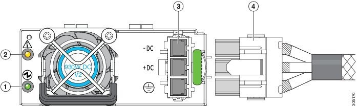
|
|
|
||
|
|
|
Installing a Version 1 930W DC Power Supply, UCSC-PSU-930WDC
If you are using a Version 1 930W DC power supply, stripped wires connect power to the removable connector block. See also Installing a Version 2 930W DC Power Supply, UCSC-PSU2V2-930DC.
Step 1![]() Turn off the DC power source from your facility’s circuit breaker to avoid electric shock hazard.
Turn off the DC power source from your facility’s circuit breaker to avoid electric shock hazard.
Step 2![]() Remove the DC power connector block from the power supply. (The spare PID for this connector is UCSC-CONN-930WDC=.)
Remove the DC power connector block from the power supply. (The spare PID for this connector is UCSC-CONN-930WDC=.)
To release the connector block from the power supply, push the orange plastic button on the top of the connector inward toward the power supply and pull the connector block out.
Step 3![]() Strip 15mm (.59 inches) of insulation off the DC wires that you will use.
Strip 15mm (.59 inches) of insulation off the DC wires that you will use.
Note![]() The recommended wire gauge is 8 AWG. The minimum wire gauge is 10 AWG.
The recommended wire gauge is 8 AWG. The minimum wire gauge is 10 AWG.
Step 4![]() Orient the connector as shown in Figure 3-33, with the orange plastic button toward the top.
Orient the connector as shown in Figure 3-33, with the orange plastic button toward the top.
Step 5![]() Use a small screwdriver to depress the spring-loaded wire retainer lever on the lower spring-cage wire connector. Insert your green (ground) wire into the aperture and then release the lever.
Use a small screwdriver to depress the spring-loaded wire retainer lever on the lower spring-cage wire connector. Insert your green (ground) wire into the aperture and then release the lever.
Step 6![]() Use a small screwdriver to depress the wire retainer lever on the middle spring-cage wire connector. Insert your black (DC negative) wire into the aperture and then release the lever.
Use a small screwdriver to depress the wire retainer lever on the middle spring-cage wire connector. Insert your black (DC negative) wire into the aperture and then release the lever.
Step 7![]() Use a small screwdriver to depress the wire retainer lever on the upper spring-cage wire connector. Insert your red (DC positive) wire into the aperture and then release the lever.
Use a small screwdriver to depress the wire retainer lever on the upper spring-cage wire connector. Insert your red (DC positive) wire into the aperture and then release the lever.
Step 8![]() Insert the connector block back into the power supply. Make sure that your red (DC positive) wire aligns with the power supply label, “+ DC”.
Insert the connector block back into the power supply. Make sure that your red (DC positive) wire aligns with the power supply label, “+ DC”.
Step 9![]() See Installation Grounding for additional information about chassis grounding.
See Installation Grounding for additional information about chassis grounding.
Figure 3-33 Version 1 930 W, –48 VDC Power Supply Connector Block

|
|
|
Installation Grounding
The AC power supplies have internal grounding and so no additional grounding is required when the supported AC power cords are used.
When using a DC power supply, additional grounding of the server chassis to the earth ground of the rack is available. Screw holes for use with your grounding lugs and grounding wires are supplied on the chassis rear panel.
Note![]() The grounding points on the chassis are sized for M5 screws. The grounding points are spaced at 0.625 inches (15.86 mm). You must provide your own screws, grounding lug, and grounding wire. The grounding lug required is a Panduit LCD10-14AF-L or equivalent. The grounding cable that you provide must be 14 AWG (2 mm), minimum 60° C wire, or as permitted by the local code.
The grounding points on the chassis are sized for M5 screws. The grounding points are spaced at 0.625 inches (15.86 mm). You must provide your own screws, grounding lug, and grounding wire. The grounding lug required is a Panduit LCD10-14AF-L or equivalent. The grounding cable that you provide must be 14 AWG (2 mm), minimum 60° C wire, or as permitted by the local code.
See Figure 3-31 for the location of the grounding lug screw-holes on the chassis rear panel.
Replacing an mLOM Card
The server can use an mLOM card to provide additional connectivity. The mLOM card socket remains powered when the server is in 12 V standby power mode and it supports the network communications services (NCSI) protocol.
Step 1![]() Power off the server as described in Shutting Down and Powering Off the Server.
Power off the server as described in Shutting Down and Powering Off the Server.
Step 2![]() Slide the server out the front of the rack far enough so that you can remove the top cover. You might have to detach cables from the rear panel to provide clearance.
Slide the server out the front of the rack far enough so that you can remove the top cover. You might have to detach cables from the rear panel to provide clearance.
Step 3![]() Remove the top cover as described in Removing and Replacing the Server Top Cover.
Remove the top cover as described in Removing and Replacing the Server Top Cover.
Step 4![]() Remove PCIe riser 1 to provide clearance. See Replacing a PCIe Riser for instructions.
Remove PCIe riser 1 to provide clearance. See Replacing a PCIe Riser for instructions.
Step 5![]() Remove any existing mLOM card or a blanking panel (see Figure 3-34):
Remove any existing mLOM card or a blanking panel (see Figure 3-34):
a.![]() Loosen the single thumbscrew that secures the mLOM card to the chassis floor.
Loosen the single thumbscrew that secures the mLOM card to the chassis floor.
b.![]() Slide the mLOM card horizontally to disengage its connector from the motherboard socket.
Slide the mLOM card horizontally to disengage its connector from the motherboard socket.
Step 6![]() Install a new mLOM card:
Install a new mLOM card:
a.![]() Set the mLOM card on the chassis floor so that its connector is aligned with the motherboard socket and its thumbscrew is aligned with the standoff on the chassis floor.
Set the mLOM card on the chassis floor so that its connector is aligned with the motherboard socket and its thumbscrew is aligned with the standoff on the chassis floor.
b.![]() Push the card’s connector into the motherboard socket horizontally.
Push the card’s connector into the motherboard socket horizontally.
c.![]() Tighten the thumbscrew to secure the card to the chassis floor.
Tighten the thumbscrew to secure the card to the chassis floor.
Step 7![]() Return PCIe riser 1 to the server. See Replacing a PCIe Riser for instructions.
Return PCIe riser 1 to the server. See Replacing a PCIe Riser for instructions.
Step 9![]() Replace the server in the rack, replace cables, and then power on the server by pressing the Power button.
Replace the server in the rack, replace cables, and then power on the server by pressing the Power button.
Figure 3-34 mLOM Card Location
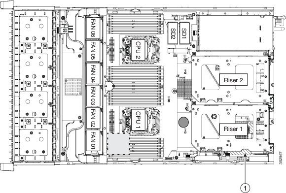
|
|
mLOM card socket location on motherboard (under PCIe riser 1) |
|
Service DIP Switches
This section includes the following topics:
- DIP Switch Location on the Motherboard
- Using the BIOS Recovery DIP Switch
- Using the Clear Password DIP Switch
- Using the Clear CMOS DIP Switch
DIP Switch Location on the Motherboard
See Figure 3-35. The position of the block of DIP switches (SW8) is shown in red. In the magnified view, all switches are shown in the default position.
Figure 3-35 Service DIP Switches
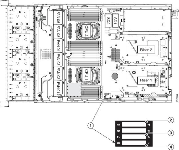
|
|
|
||
|
|
|
Using the BIOS Recovery DIP Switch
Note![]() The following procedures use a
The following procedures use a recovery.cap recovery file. In Cisco IMC releases 3.0(1) and later, this recovery file has been renamed bios.cap.
Depending on which stage the BIOS becomes corrupted, you might see different behavior.
Note![]() As indicated by the message shown above, there are two procedures for recovering the BIOS. Try procedure 1 first. If that procedure does not recover the BIOS, use procedure 2.
As indicated by the message shown above, there are two procedures for recovering the BIOS. Try procedure 1 first. If that procedure does not recover the BIOS, use procedure 2.
Procedure 1: Reboot with recovery.cap (or bios.cap) File
Step 1![]() Download the BIOS update package and extract it to a temporary location.
Download the BIOS update package and extract it to a temporary location.
Step 2![]() Copy the contents of the extracted recovery folder to the root directory of a USB thumb drive. The recovery folder contains the
Copy the contents of the extracted recovery folder to the root directory of a USB thumb drive. The recovery folder contains the recovery.cap (or bios.cap) file that is required in this procedure.
Note![]() The
The recovery.cap (or bios.cap) file must be in the root directory of the USB thumb drive. Do not rename this file. The USB thumb drive must be formatted with either FAT16 or FAT32 file systems.
Step 3![]() Insert the USB thumb drive into a USB port on the server.
Insert the USB thumb drive into a USB port on the server.
Step 5![]() Return the server to main power mode by pressing the Power button on the front panel.
Return the server to main power mode by pressing the Power button on the front panel.
The server boots with the updated BIOS boot block. When the BIOS detects a valid recovery.cap (or bios.cap) file on the USB thumb drive, it displays this message:
System would flash the BIOS image now...
System would restart with recovered image after a few seconds...
Step 6![]() Wait for server to complete the BIOS update, and then remove the USB thumb drive from the server.
Wait for server to complete the BIOS update, and then remove the USB thumb drive from the server.
Note![]() During the BIOS update, Cisco IMC shuts down the server and the screen goes blank for about 10 minutes. Do not unplug the power cords during this update. Cisco IMC powers on the server after the update is complete.
During the BIOS update, Cisco IMC shuts down the server and the screen goes blank for about 10 minutes. Do not unplug the power cords during this update. Cisco IMC powers on the server after the update is complete.
Procedure 2: Use BIOS Recovery DIP switch and recovery.cap (or bios.cap) File
See Figure 3-35 for the location of the SW8 block of DIP switches.
Step 1![]() Download the BIOS update package and extract it to a temporary location.
Download the BIOS update package and extract it to a temporary location.
Step 2![]() Copy the contents of the extracted recovery folder to the root directory of a USB thumb drive. The recovery folder contains the recovery.cap (or ios.cap) file that is required in this procedure.
Copy the contents of the extracted recovery folder to the root directory of a USB thumb drive. The recovery folder contains the recovery.cap (or ios.cap) file that is required in this procedure.
Note![]() The recovery.cap (or bios.cap) file must be in the root directory of the USB thumb drive. Do not rename this file. The USB thumb drive must be formatted with either FAT16 or FAT32 file systems.
The recovery.cap (or bios.cap) file must be in the root directory of the USB thumb drive. Do not rename this file. The USB thumb drive must be formatted with either FAT16 or FAT32 file systems.
Step 3![]() Power off the server as described in Shutting Down and Powering Off the Server.
Power off the server as described in Shutting Down and Powering Off the Server.
Step 4![]() Disconnect all power cords from the power supplies.
Disconnect all power cords from the power supplies.
Step 5![]() Slide the server out the front of the rack far enough so that you can remove the top cover. You might have to detach cables from the rear panel to provide clearance.
Slide the server out the front of the rack far enough so that you can remove the top cover. You might have to detach cables from the rear panel to provide clearance.
Step 6![]() Remove the top cover as described in Removing and Replacing the Server Top Cover.
Remove the top cover as described in Removing and Replacing the Server Top Cover.
Step 7![]() Slide the BIOS recovery DIP switch from position 1 to the closed position (see Figure 3-35).
Slide the BIOS recovery DIP switch from position 1 to the closed position (see Figure 3-35).
Step 8![]() Reconnect AC power cords to the server. The server powers up to standby power mode.
Reconnect AC power cords to the server. The server powers up to standby power mode.
Step 9![]() Insert the USB thumb drive that you prepared in Step 2 into a USB port on the server.
Insert the USB thumb drive that you prepared in Step 2 into a USB port on the server.
Step 10![]() Return the server to main power mode by pressing the Power button on the front panel.
Return the server to main power mode by pressing the Power button on the front panel.
The server boots with the updated BIOS boot block. When the BIOS detects a valid recovery.cap (or bios.cap) file on the USB thumb drive, it displays this message:
System would flash the BIOS image now...
System would restart with recovered image after a few seconds...
Step 11![]() Wait for server to complete the BIOS update, and then remove the USB thumb drive from the server.
Wait for server to complete the BIOS update, and then remove the USB thumb drive from the server.
Note![]() During the BIOS update, Cisco IMC shuts down the server and the screen goes blank for about 10 minutes. Do not unplug the power cords during this update. Cisco IMC powers on the server after the update is complete.
During the BIOS update, Cisco IMC shuts down the server and the screen goes blank for about 10 minutes. Do not unplug the power cords during this update. Cisco IMC powers on the server after the update is complete.
Step 12![]() After the server has fully booted, power off the server again and disconnect all power cords.
After the server has fully booted, power off the server again and disconnect all power cords.
Step 13![]() Slide the BIOS recovery DIP switch from the closed position back to the default position 1.
Slide the BIOS recovery DIP switch from the closed position back to the default position 1.
Note![]() If you do not move the jumper, after recovery completion you see the prompt, “Please remove the recovery jumper.”
If you do not move the jumper, after recovery completion you see the prompt, “Please remove the recovery jumper.”
Step 14![]() Replace the top cover, replace the server in the rack, replace power cords and any other cables, and then power on the server by pressing the Power button.
Replace the top cover, replace the server in the rack, replace power cords and any other cables, and then power on the server by pressing the Power button.
Using the Clear Password DIP Switch
See Figure 3-35 for the location of this DIP switch. You can use this switch to clear the administrator password.
Step 1![]() Power off the server as described in Shutting Down and Powering Off the Server.
Power off the server as described in Shutting Down and Powering Off the Server.
Step 2![]() Disconnect all power cords from the power supplies.
Disconnect all power cords from the power supplies.
Step 3![]() Slide the server out the front of the rack far enough so that you can remove the top cover. You might have to detach cables from the rear panel to provide clearance.
Slide the server out the front of the rack far enough so that you can remove the top cover. You might have to detach cables from the rear panel to provide clearance.
Step 4![]() Remove the top cover as described in Removing and Replacing the Server Top Cover.
Remove the top cover as described in Removing and Replacing the Server Top Cover.
Step 5![]() Slide the clear password DIP switch from position 2 to the closed position (see Figure 3-35).
Slide the clear password DIP switch from position 2 to the closed position (see Figure 3-35).
Step 6![]() Reinstall the top cover and reconnect AC power cords to the server. The server powers up to standby power mode, indicated when the Power LED on the front panel is amber.
Reinstall the top cover and reconnect AC power cords to the server. The server powers up to standby power mode, indicated when the Power LED on the front panel is amber.
Step 7![]() Return the server to main power mode by pressing the Power button on the front panel. The server is in main power mode when the Power LED is green.
Return the server to main power mode by pressing the Power button on the front panel. The server is in main power mode when the Power LED is green.
Note![]() You must allow the entire server, not just the service processor, to reboot to main power mode to complete the reset. The state of the jumper cannot be determined without the host CPU running.
You must allow the entire server, not just the service processor, to reboot to main power mode to complete the reset. The state of the jumper cannot be determined without the host CPU running.
Step 8![]() Press the Power button to shut down the server to standby power mode, and then remove AC power cords from the server to remove all power.
Press the Power button to shut down the server to standby power mode, and then remove AC power cords from the server to remove all power.
Step 9![]() Remove the top cover from the server.
Remove the top cover from the server.
Step 10![]() Slide the clear password DIP switch from the closed position back to default position 2 (see Figure 3-35).
Slide the clear password DIP switch from the closed position back to default position 2 (see Figure 3-35).
Note![]() If you do not move the jumper, the password is cleared every time that you power-cycle the server.
If you do not move the jumper, the password is cleared every time that you power-cycle the server.
Step 11![]() Replace the top cover, replace the server in the rack, replace power cords and any other cables, and then power on the server by pressing the Power button.
Replace the top cover, replace the server in the rack, replace power cords and any other cables, and then power on the server by pressing the Power button.
Using the Clear CMOS DIP Switch
See Figure 3-35 for the location of this DIP switch. You can use this switch to clear the server’s CMOS settings in the case of a system hang. For example, if the server hangs because of incorrect settings and does not boot, use this jumper to invalidate the settings and reboot with defaults.
Step 1![]() Power off the server as described in Shutting Down and Powering Off the Server.
Power off the server as described in Shutting Down and Powering Off the Server.
Step 2![]() Disconnect all power cords from the power supplies.
Disconnect all power cords from the power supplies.
Step 3![]() Slide the server out the front of the rack far enough so that you can remove the top cover. You might have to detach cables from the rear panel to provide clearance.
Slide the server out the front of the rack far enough so that you can remove the top cover. You might have to detach cables from the rear panel to provide clearance.
Step 4![]() Remove the top cover as described in Removing and Replacing the Server Top Cover.
Remove the top cover as described in Removing and Replacing the Server Top Cover.
Step 5![]() Slide the clear CMOS DIP switch from position 4 to the closed position (see Figure 3-35).
Slide the clear CMOS DIP switch from position 4 to the closed position (see Figure 3-35).
Step 6![]() Reinstall the top cover and reconnect AC power cords to the server. The server powers up to standby power mode, indicated when the Power LED on the front panel is amber.
Reinstall the top cover and reconnect AC power cords to the server. The server powers up to standby power mode, indicated when the Power LED on the front panel is amber.
Step 7![]() Return the server to main power mode by pressing the Power button on the front panel. The server is in main power mode when the Power LED is green.
Return the server to main power mode by pressing the Power button on the front panel. The server is in main power mode when the Power LED is green.
Note![]() You must allow the entire server, not just the service processor, to reboot to main power mode to complete the reset. The state of the jumper cannot be determined without the host CPU running.
You must allow the entire server, not just the service processor, to reboot to main power mode to complete the reset. The state of the jumper cannot be determined without the host CPU running.
Step 8![]() Press the Power button to shut down the server to standby power mode, and then remove AC power cords from the server to remove all power.
Press the Power button to shut down the server to standby power mode, and then remove AC power cords from the server to remove all power.
Step 9![]() Remove the top cover from the server.
Remove the top cover from the server.
Step 10![]() Move the clear CMOS DIP switch from the closed position back to default position 4 (see Figure 3-35).
Move the clear CMOS DIP switch from the closed position back to default position 4 (see Figure 3-35).
Note![]() If you do not move the jumper, the CMOS settings are reset to the default every time that you power-cycle the server.
If you do not move the jumper, the CMOS settings are reset to the default every time that you power-cycle the server.
Step 11![]() Replace the top cover, replace the server in the rack, replace power cords and any other cables, and then power on the server by pressing the Power button.
Replace the top cover, replace the server in the rack, replace power cords and any other cables, and then power on the server by pressing the Power button.
 Feedback