FlexPod with Cisco AI POD: Infrastructure for AI Training and Fine-Tuning Deployment Guide
Available Languages
Bias-Free Language
The documentation set for this product strives to use bias-free language. For the purposes of this documentation set, bias-free is defined as language that does not imply discrimination based on age, disability, gender, racial identity, ethnic identity, sexual orientation, socioeconomic status, and intersectionality. Exceptions may be present in the documentation due to language that is hardcoded in the user interfaces of the product software, language used based on RFP documentation, or language that is used by a referenced third-party product. Learn more about how Cisco is using Inclusive Language.
- US/Canada 800-553-2447
- Worldwide Support Phone Numbers
- All Tools
 Feedback
 Feedback
![]()
In partnership with:

About the Cisco Validated Design Program
The Cisco Validated Design (CVD) program consists of systems and solutions designed, tested, and documented to facilitate faster, more reliable, and more predictable customer deployments. For more information, go to: http://www.cisco.com/go/designzone.
Cisco AI PODs are modular, pre-validated infrastructure solutions designed to accelerate the entire AI lifecycle, including training, fine-tuning, and high-throughput inferencing. They leverage Cisco UCS compute, Cisco Nexus networking, advanced GPUs, and integrated software such as NVIDIA AI Enterprise and RedHat OpenShift to deliver scalable, secure, and efficient AI infrastructure suitable for both data center and edge deployments. These PODs simplify AI adoption by providing centralized management through Cisco Intersight and Nexus Dashboard, enabling rapid deployment, automation, and operational visibility. Supporting diverse AI workloads like large language models, generative AI, and real-time analytics, Cisco AI PODs offer flexible configurations tailored to various business needs and cost models. Backed by Cisco Validated Designs and partner storage options, they ensure reliability, performance, and seamless integration within existing IT environments, helping organizations innovate and scale AI with confidence and reduced complexity.
Combining Cisco AI PODs with FlexPod Datacenter creates a powerful, scalable, and validated infrastructure solution optimized for AI and machine learning workloads. FlexPod Datacenter provides a converged architecture integrating Cisco UCS servers, Cisco Nexus switches, and NetApp storage, designed for high availability and flexibility. When integrated with Cisco AI PODs, which include advanced GPU capabilities and AI-optimized compute resources, the combined solution supports accelerated AI lifecycle processes such as training, inferencing, and model deployment. This integration leverages Cisco UCS servers, NVIDIA GPUs, and software platforms like NVIDIA Base Command Manager and Red Hat OpenShift to deliver a unified environment that simplifies AI infrastructure management through Cisco Intersight. The solution offers high-speed networking, persistent storage, and automation playbooks to reduce deployment time and operational complexity, enabling enterprises to scale AI workloads efficiently while maintaining security and operational visibility. This combined approach supports diverse AI use cases, including generative AI and MLOps, with validated designs that minimize risk and maximize performance in enterprise data centers.
For information about the FlexPod design and deployment details, including the configuration of various elements of design and associated best practices, refer to Cisco Validated Designs for FlexPod, here: https://www.cisco.com/c/en/us/solutions/design-zone/data-center-design-guides/flexpod-design-guides.html.
Solution Overview
This chapter contains the following:
● Purpose of this documentPurpose of this document
● New in this releaseNew in this release
The intended audience of this document includes but is not limited to IT architects, sales engineers, field consultants, professional services, IT managers, partner engineering, and customers who want to take advantage of an infrastructure built to deliver IT efficiency and enable IT innovation.
This document provides deployment guidance around setting up Cisco AI PODs with Cisco UCS C885A M8 servers along with FlexPod Datacenter for AI training and fine-tuning use cases. This configuration is built as a tenant on top of FlexPod Base and assumes FlexPod Base has already been configured. This document introduces various design elements and explains various considerations and best practices for successful deployment.
The following design elements distinguish this version of FlexPod from previous models:
Configuration of AI PODs with NetApp Storage first with NVIDIA Base Command Manager and running sample training workloads. ● Configuration of AI PODs with NetApp Storage first with NVIDIA Base Command Manager and running sample training workloads.
● Adding the Cisco UCS C885A M8 nodes to an existing OpenShift cluster and setting up the East-West or backend networking.
Deployment Hardware and Software
This chapter contains the following:
● Design RequirementsDesign Requirements
● NetApp ONTAP DesignNetApp ONTAP Design
● Physical TopologyPhysical Topology
● Software RevisionsSoftware Revisions
● FlexPod CablingFlexPod Cabling
The FlexPod Datacenter with Cisco UCS and Cisco Intersight meets the following general design requirements:
● Resilient design across all layers of the infrastructure with no single point of failure
● Scalable design with the flexibility to add compute capacity, storage, or network bandwidth as needed
● Modular design that can be replicated to expand and grow as the needs of the business grow
● Flexible design that can support different models of various components with ease
● Simplified design with the ability to integrate and automate with external automation tools
● Cloud-enabled design which can be configured, managed, and orchestrated from the cloud using GUI or APIs
To deliver a solution which meets all these design requirements, various solution components are connected and configured as explained in the following sections.
For the AI POD networking and server design, please refer to the Cisco AI POD for Enterprise Training and Fine-Tuning Design Guide - Cisco. Only the NetApp ONTAP Design is listed in this document.
The storage system and design is a critical component of the AI training and fine-tuning infrastructure. AI workloads require high-performance, scalability, and secure access to storage to read large training datasets and to write model checkpoints, logging, and other artifacts during the training process. A key storage requirement is for very high-throughput sequential reads, as massive datasets may need to be loaded into GPU memory at the beginning of each training epoch.
The NetApp AFF A90 storage system is a 4RU chassis containing 2 controllers that operate as high availability partners (HA Pair) for each other, with up to 48 2.5-inch form-factor solid state disks (SSD). Each controller is connected to a separate pair of Cisco Nexus 9332D-GX2B leaf switches (frontend fabric) using two 100GE connectivity providing general NFS v3 and v4 services, and as well as S3 access to shared filesystems if desired. To enable high performance and scalability, the storage controllers form a storage cluster that enables the entire performance and capacity of the cluster nodes to be combined into a single namespace called a FlexGroup with data distributed across the disks of each node in the cluster.
The storage cluster also supports NFS v4.1 with Parallel NFS (pNFS) that enables clients to establish connections directly to every controller in the cluster. Additionally, session trunking combines the performance from multiple physical interfaces into a single session, enabling even single-threaded workloads to access more network bandwidth than is possible with traditional ethernet bonding. Combining all these features with RDMA enables the AFF A90 storage system to deliver low latency and high throughput that scales linearly for workloads leveraging NVIDIA GPUDirect Storage. The NVIDIA Enterprise Reference Architecture (ERA) provides the guidance to do the scaling of AFF A90 storage nodes along with Cisco C series GPU nodes
The AI PODs with FlexPod Datacenter with Red Hat OpenShift on Bare Metal infrastructure configuration is shown here. The AI PODs with FlexPod Datacenter with NVIDIA Base Command Manager
● Cisco UCS C885A M8 servers each with 8 NVIDIA H200 GPUs
● Cisco UCS X9508 Chassis with eight Cisco UCS X210c Compute Nodes for OpenShift cluster nodes and supporting services
● Cisco UCS X-Series Direct Fabric Interconnects 9108 to support 100GbE connectivity from various components
● High-speed Cisco NX-OS-based Nexus 9332D-GX2B and 9364D-GX2A switching design to support 100GE and 400GE connectivity
● NetApp AFF A90 storage controllers 100/200G Ethernet
The software components of this solution consist of:
● Cisco Intersight to deploy, maintain, monitor and support the Cisco UCS server components
● Cisco Nexus Dashboard to deploy, maintain, and support the Cisco Nexus Switching Fabrics
● NVIDIA Base Command Manager to orchestrate training workloads on Ubuntu
● Red Hat OpenShift which provides a platform for both containers and VMs
FlexPod Datacenter with AI PODs Topology
Figure 1 shows various hardware components and the network connections for this IP-based FlexPod design.
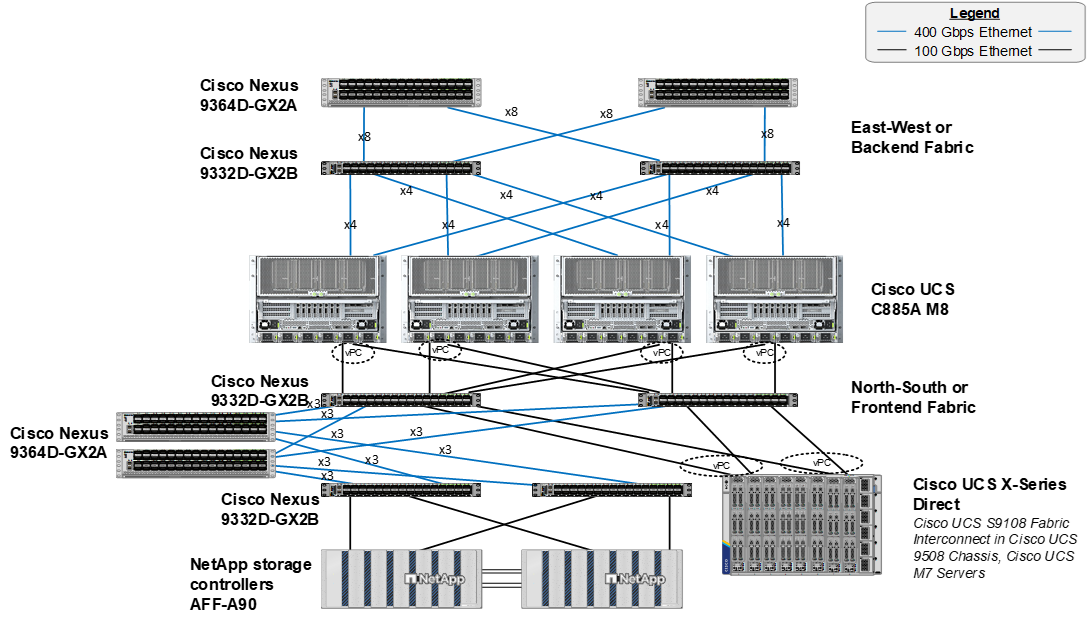
The reference hardware configuration includes:
● A scalable East-West or Backend fully non-blocking Spine Leaf fabric consisting of Cisco Nexus 9332D-GX2B leafs and Nexus 9364D-GX2A spines.
● 4 or more Cisco UCS C885A M8 servers, each with 8 NVIDIA H200 SXM GPUs.
● A scalable North-South or Frontend Spine Leaf fabric consisting of Cisco Nexus 9332D-GX2B leafs and Nexus 9364D-GX2A spines. This fabric has dedicated storage and compute leaf pairs.
● Two Cisco UCS Fabric Interconnects 9108 100G (FIs) in the chassis provide the chassis connectivity. At least two 100 Gigabit Ethernet ports from each FI, configured as a Port-Channel, are connected to each Nexus 9332D-GX2B switch in the North-South or Frontend Spine Leaf fabric. 25 Gigabit Ethernet connectivity is also supported as well as other versions of the Cisco UCS FI that would be used with Intelligent Fabric Modules (IFMs) in the chassis.
● One Cisco UCS X9508 Chassis contains up to 8 Cisco UCS X210c servers for OpenShift cluster nodes and supporting services nodes for services such as DNS/DHCP or configuration VMs.
● One NetApp AFF A90 HA pair connects to the Cisco Nexus 9332D-GX2B Switches using two 100 GE ports from each controller configured as individual links. 200GE connectivity is also supported when NVIDIA ConnectX-7 cards in the NetApp storage controllers are used.
Note: Only identically configured Cisco UCS C885A M8 servers should be added to an OpenShift cluster. Adding servers with different port configurations, such as Cisco UCS C-Series servers with only one ConnectX-7 will cause issues with Nic Cluster Policy in the NVIDIA Network Operator.
Table 1 lists VLANs configured for setting up the FlexPod environment along with their usage.
| VLAN ID |
Name |
Usage |
IP Subnet used in this deployment |
| 2* |
Native-VLAN |
Use VLAN 2 as native VLAN instead of default VLAN (1) |
|
| 550* |
OOB-MGMT-VLAN |
Out-of-band management VLAN to connect management ports for various devices |
10.115.90.0/26; GW: 10.115.90.1 |
| 703 |
OCP/Ubuntu-BareMetal-MGMT |
Routable VLAN used for Ubuntu management and OpenShift cluster and node management |
10.115.90.64/26; GW: 10.115.90.126 |
| 3051 |
NFS |
Used for Ubuntu storage and OpenShift NFS RWX Persistent Storage |
192.168.51.0/24 |
Note: *VLAN configured in FlexPod Base. In setting up FlexPod Base, the Nexus switch portion will not be set up.
Note: S3 object storage was also used in this environment. It was determined that OpenShift uses the management network to reach S3 storage. A separate VLAN, subnet and vNIC was not defined for S3.
Table 2 lists the VMs or bare metal servers necessary for deployment as outlined in this document.
| Virtual Machine Description |
VLAN |
IP Address |
Comments |
| AD1 |
703 |
10.115.90.123 |
Hosted on pre-existing management infrastructure within the FlexPod |
| AD2 |
703 |
10.115.90.124 |
Hosted on pre-existing management infrastructure within the FlexPod |
| OCP Installer |
703 |
10.115.90.65 |
Hosted on pre-existing management infrastructure within the FlexPod |
| NVIDIA Base Command Head Node |
703 |
10.115.90.115 |
Hosted on pre-existing management infrastructure within the FlexPod |
Table 3 lists the software revisions for various components of the solution.
| Layer |
Device |
Image Bundle |
Comments |
| Compute |
Cisco C885A M8 Firmware Package |
1.1(0.250025) |
Upgrades all server components |
|
|
Cisco UCS X210c M6 |
5.3(5.250021) |
Used for OpenShift Control Plane / Worker Nodes |
|
|
Cisco UCS Fabric Interconnect 9108 100G |
4.3(5.240162) |
|
| Network |
Cisco Nexus Dashboard |
4.1.1g |
|
| Cisco Nexus 9332D-GX2B NX-OS |
10.4(5) |
|
|
| Cisco Nexus 9364D-GX2A NX-OS |
10.4(5) |
|
|
| Storage |
NetApp AFF A90 |
ONTAP 9.15.1P7 |
Although ONTAP 9.15.1 was used for this validation |
| Software |
Red Hat OpenShift |
4.16 |
|
| NetApp Trident |
25.6.2 |
|
|
| NVIDIA H200 GPU Driver - Ubuntu |
570.133.20 |
|
|
|
|
NVIDIA H200 GPU CUDA Version - Ubuntu |
12.8 |
|
Table 4. Cisco Nexus Backend Fabric Cable Connections
| Device |
Port |
Speed |
Device |
Port |
Comment |
| BE-LF1 |
mgmt0 |
1G |
management switch |
||
| BE-LF1 |
Eth1/1 |
400G |
C885A-1 |
CX-7 1 |
|
| BE-LF1 |
Eth1/2 |
400G |
C885A-1 |
CX-7 3 |
|
| BE-LF1 |
Eth1/3 |
400G |
C885A-1 |
CX-7 5 |
|
| BE-LF1 |
Eth1/4 |
400G |
C885A-1 |
CX-7 7 |
|
| BE-LF1 |
Eth1/5 |
400G |
C885A-2 |
CX-7 1 |
|
| BE-LF1 |
Eth1/6 |
400G |
C885A-2 |
CX-7 3 |
|
| BE-LF1 |
Eth1/7 |
400G |
C885A-2 |
CX-7 5 |
|
| BE-LF1 |
Eth1/8 |
400G |
C885A-2 |
CX-7 7 |
|
| BE-LF1 |
Eth1/9 |
400G |
C885A-3 |
CX-7 1 |
|
| BE-LF1 |
Eth1/10 |
400G |
C885A-3 |
CX-7 3 |
|
| BE-LF1 |
Eth1/11 |
400G |
C885A-3 |
CX-7 5 |
|
| BE-LF1 |
Eth1/12 |
400G |
C885A-3 |
CX-7 7 |
|
| BE-LF1 |
Eth1/13 |
400G |
C885A-4 |
CX-7 1 |
|
| BE-LF1 |
Eth1/14 |
400G |
C885A-4 |
CX-7 3 |
|
| BE-LF1 |
Eth1/15 |
400G |
C885A-4 |
CX-7 5 |
|
| BE-LF1 |
Eth1/16 |
400G |
C885A-4 |
CX-7 7 |
|
| BE-LF1 |
Eth1/17 |
400G |
BE-SP1 |
Eth1/1 |
|
| BE-LF1 |
Eth1/18 |
400G |
BE-SP1 |
Eth1/2 |
|
| BE-LF1 |
Eth1/19 |
400G |
BE-SP1 |
Eth1/3 |
|
| BE-LF1 |
Eth1/20 |
400G |
BE-SP1 |
Eth1/4 |
|
| BE-LF1 |
Eth1/21 |
400G |
BE-SP1 |
Eth1/5 |
|
| BE-LF1 |
Eth1/22 |
400G |
BE-SP1 |
Eth1/6 |
|
| BE-LF1 |
Eth1/23 |
400G |
BE-SP1 |
Eth1/7 |
|
| BE-LF1 |
Eth1/24 |
400G |
BE-SP1 |
Eth1/8 |
|
| BE-LF1 |
Eth1/25 |
400G |
BE-SP2 |
Eth1/1 |
|
| BE-LF1 |
Eth1/26 |
400G |
BE-SP2 |
Eth1/2 |
|
| BE-LF1 |
Eth1/27 |
400G |
BE-SP2 |
Eth1/3 |
|
| BE-LF1 |
Eth1/28 |
400G |
BE-SP2 |
Eth1/4 |
|
| BE-LF1 |
Eth1/29 |
400G |
BE-SP2 |
Eth1/5 |
|
| BE-LF1 |
Eth1/30 |
400G |
BE-SP2 |
Eth1/6 |
|
| BE-LF1 |
Eth1/31 |
400G |
BE-SP2 |
Eth1/7 |
|
| BE-LF1 |
Eth1/32 |
400G |
BE-SP2 |
Eth1/8 |
|
| BE-LF2 |
mgmt0 |
1G |
management switch |
||
| BE-LF2 |
Eth1/1 |
400G |
C885A-1 |
CX-7 2 |
|
| BE-LF2 |
Eth1/2 |
400G |
C885A-1 |
CX-7 2 |
|
| BE-LF2 |
Eth1/3 |
400G |
C885A-1 |
CX-7 6 |
|
| BE-LF2 |
Eth1/4 |
400G |
C885A-1 |
CX-7 8 |
|
| BE-LF2 |
Eth1/5 |
400G |
C885A-2 |
CX-7 2 |
|
| BE-LF2 |
Eth1/6 |
400G |
C885A-2 |
CX-7 2 |
|
| BE-LF2 |
Eth1/7 |
400G |
C885A-2 |
CX-7 6 |
|
| BE-LF2 |
Eth1/8 |
400G |
C885A-2 |
CX-7 8 |
|
| BE-LF2 |
Eth1/9 |
400G |
C885A-3 |
CX-7 2 |
|
| BE-LF2 |
Eth1/10 |
400G |
C885A-3 |
CX-7 2 |
|
| BE-LF2 |
Eth1/11 |
400G |
C885A-3 |
CX-7 6 |
|
| BE-LF2 |
Eth1/12 |
400G |
C885A-3 |
CX-7 8 |
|
| BE-LF2 |
Eth1/13 |
400G |
C885A-4 |
CX-7 2 |
|
| BE-LF2 |
Eth1/14 |
400G |
C885A-4 |
CX-7 2 |
|
| BE-LF2 |
Eth1/15 |
400G |
C885A-4 |
CX-7 6 |
|
| BE-LF2 |
Eth1/16 |
400G |
C885A-4 |
CX-7 8 |
|
| BE-LF2 |
Eth1/17 |
400G |
BE-SP1 |
Eth1/9 |
|
| BE-LF2 |
Eth1/18 |
400G |
BE-SP1 |
Eth1/10 |
|
| BE-LF2 |
Eth1/19 |
400G |
BE-SP1 |
Eth1/11 |
|
| BE-LF2 |
Eth1/20 |
400G |
BE-SP1 |
Eth1/12 |
|
| BE-LF2 |
Eth1/21 |
400G |
BE-SP1 |
Eth1/13 |
|
| BE-LF2 |
Eth1/22 |
400G |
BE-SP1 |
Eth1/14 |
|
| BE-LF2 |
Eth1/23 |
400G |
BE-SP1 |
Eth1/15 |
|
| BE-LF2 |
Eth1/24 |
400G |
BE-SP1 |
Eth1/16 |
|
| BE-LF2 |
Eth1/25 |
400G |
BE-SP2 |
Eth1/9 |
|
| BE-LF2 |
Eth1/26 |
400G |
BE-SP2 |
Eth1/10 |
|
| BE-LF2 |
Eth1/27 |
400G |
BE-SP2 |
Eth1/11 |
|
| BE-LF2 |
Eth1/28 |
400G |
BE-SP2 |
Eth1/12 |
|
| BE-LF2 |
Eth1/29 |
400G |
BE-SP2 |
Eth1/13 |
|
| BE-LF2 |
Eth1/30 |
400G |
BE-SP2 |
Eth1/14 |
|
| BE-LF2 |
Eth1/31 |
400G |
BE-SP2 |
Eth1/15 |
|
| BE-LF2 |
Eth1/32 |
400G |
BE-SP2 |
Eth1/16 |
|
| BE-SP1 |
mgmt0 |
1G |
management switch |
||
| BE-SP1 |
Eth1/1 |
400G |
BE-LF1 |
Eth1/17 |
|
| BE-SP1 |
Eth1/2 |
400G |
BE-LF1 |
Eth1/18 |
|
| BE-SP1 |
Eth1/3 |
400G |
BE-LF1 |
Eth1/19 |
|
| BE-SP1 |
Eth1/4 |
400G |
BE-LF1 |
Eth1/20 |
|
| BE-SP1 |
Eth1/5 |
400G |
BE-LF1 |
Eth1/21 |
|
| BE-SP1 |
Eth1/6 |
400G |
BE-LF1 |
Eth1/22 |
|
| BE-SP1 |
Eth1/7 |
400G |
BE-LF1 |
Eth1/23 |
|
| BE-SP1 |
Eth1/8 |
400G |
BE-LF1 |
Eth1/24 |
|
| BE-SP1 |
Eth1/9 |
400G |
BE-LF2 |
Eth1/17 |
|
| BE-SP1 |
Eth1/10 |
400G |
BE-LF2 |
Eth1/18 |
|
| BE-SP1 |
Eth1/11 |
400G |
BE-LF2 |
Eth1/19 |
|
| BE-SP1 |
Eth1/12 |
400G |
BE-LF2 |
Eth1/20 |
|
| BE-SP1 |
Eth1/13 |
400G |
BE-LF2 |
Eth1/21 |
|
| BE-SP1 |
Eth1/14 |
400G |
BE-LF2 |
Eth1/22 |
|
| BE-SP1 |
Eth1/15 |
400G |
BE-LF2 |
Eth1/23 |
|
| BE-SP1 |
Eth1/16 |
400G |
BE-LF2 |
Eth1/24 |
|
| BE-SP2 |
mgmt0 |
1G |
management switch |
||
| BE-SP2 |
Eth1/1 |
400G |
BE-LF1 |
Eth1/25 |
|
| BE-SP2 |
Eth1/2 |
400G |
BE-LF1 |
Eth1/26 |
|
| BE-SP2 |
Eth1/3 |
400G |
BE-LF1 |
Eth1/27 |
|
| BE-SP2 |
Eth1/4 |
400G |
BE-LF1 |
Eth1/28 |
|
| BE-SP2 |
Eth1/5 |
400G |
BE-LF1 |
Eth1/29 |
|
| BE-SP2 |
Eth1/6 |
400G |
BE-LF1 |
Eth1/30 |
|
| BE-SP2 |
Eth1/7 |
400G |
BE-LF1 |
Eth1/31 |
|
| BE-SP2 |
Eth1/8 |
400G |
BE-LF1 |
Eth1/32 |
|
| BE-SP2 |
Eth1/9 |
400G |
BE-LF2 |
Eth1/25 |
|
| BE-SP2 |
Eth1/10 |
400G |
BE-LF2 |
Eth1/26 |
|
| BE-SP2 |
Eth1/11 |
400G |
BE-LF2 |
Eth1/27 |
|
| BE-SP2 |
Eth1/12 |
400G |
BE-LF2 |
Eth1/28 |
|
| BE-SP2 |
Eth1/13 |
400G |
BE-LF2 |
Eth1/29 |
|
| BE-SP2 |
Eth1/14 |
400G |
BE-LF2 |
Eth1/30 |
|
| BE-SP2 |
Eth1/15 |
400G |
BE-LF2 |
Eth1/31 |
|
| BE-SP2 |
Eth1/16 |
400G |
BE-LF2 |
Eth1/32 |
Table 5. Cisco Nexus Frontend Fabric Cable Connections
| Device |
Port |
Speed |
Device |
Port |
Comment |
| FE-LF1 |
mgmt0 |
1G |
management switch |
||
| FE-LF1 |
Eth1/1 |
200G |
C885A-1 |
BF 1 |
|
| FE-LF1 |
Eth1/2 |
200G |
C885A-2 |
BF 1 |
|
| FE-LF1 |
Eth1/3 |
200G |
C885A-3 |
BF 1 |
|
| FE-LF1 |
Eth1/4 |
200G |
C885A-4 |
BF 1 |
|
| FE-LF1 |
Eth1/5 |
100G |
S9108-A |
Eth1/5 |
UCS X-Series Direct |
| FE-LF1 |
Eth1/6 |
100G |
S9108-B |
Eth1/5 |
UCS X-Series Direct |
| FE-LF1 |
Eth1/7 |
100G |
S9108-A |
Eth1/6 |
UCS X-Series Direct |
| FE-LF1 |
Eth1/8 |
100G |
S9108-B |
Eth1/6 |
UCS X-Series Direct |
| FE-LF1 |
Eth1/20/1 |
100G |
C225M6-1 |
VIC 1 |
|
| FE-LF1 |
Eth1/20/2 |
100G |
C225M6-2 |
VIC 1 |
|
| FE-LF1 |
Eth1/20/3 |
100G |
C225M6-3 |
VIC 1 |
|
| FE-LF1 |
Eth1/20/4 |
100G |
C225M6-4 |
VIC 1 |
|
| FE-LF1 |
Eth1/21 |
100G |
RTP5-BCM-MGMT |
VIC 1 |
BCM Head Node |
| FE-LF1 |
Eth1/27 |
400G |
FE-SP1 |
Eth1/7 |
|
| FE-LF1 |
Eth1/28 |
400G |
FE-SP1 |
Eth1/8 |
|
| FE-LF1 |
Eth1/29 |
400G |
FE-SP1 |
Eth1/9 |
|
| FE-LF1 |
Eth1/30 |
400G |
FE-SP2 |
Eth1/7 |
|
| FE-LF1 |
Eth1/31 |
400G |
FE-SP2 |
Eth1/8 |
|
| FE-LF1 |
Eth1/32 |
400G |
FE-SP2 |
Eth1/9 |
|
| FE-LF2 |
mgmt0 |
1G |
management switch |
||
| FE-LF2 |
Eth1/1 |
200G |
C885A-1 |
BF 2 |
|
| FE-LF2 |
Eth1/2 |
200G |
C885A-2 |
BF 2 |
|
| FE-LF2 |
Eth1/3 |
200G |
C885A-3 |
BF 2 |
|
| FE-LF2 |
Eth1/4 |
200G |
C885A-4 |
BF 2 |
|
| FE-LF2 |
Eth1/5 |
100G |
S9108-A |
Eth1/7 |
UCS X-Series Direct |
| FE-LF2 |
Eth1/6 |
100G |
S9108-B |
Eth1/7 |
UCS X-Series Direct |
| FE-LF2 |
Eth1/7 |
100G |
S9108-A |
Eth1/8 |
UCS X-Series Direct |
| FE-LF2 |
Eth1/8 |
100G |
S9108-B |
Eth1/8 |
UCS X-Series Direct |
| FE-LF2 |
Eth1/20/1 |
100G |
C225M6-1 |
VIC 2 |
|
| FE-LF2 |
Eth1/20/2 |
100G |
C225M6-2 |
VIC 2 |
|
| FE-LF2 |
Eth1/20/3 |
100G |
C225M6-3 |
VIC 2 |
|
| FE-LF2 |
Eth1/20/4 |
100G |
C225M6-4 |
VIC 2 |
|
| FE-LF2 |
Eth1/21 |
100G |
RTP5-BCM-MGMT |
VIC 2 |
BCM Head Node |
| FE-LF2 |
Eth1/27 |
400G |
FE-SP1 |
Eth1/10 |
|
| FE-LF2 |
Eth1/28 |
400G |
FE-SP1 |
Eth1/11 |
|
| FE-LF2 |
Eth1/29 |
400G |
FE-SP1 |
Eth1/12 |
|
| FE-LF2 |
Eth1/30 |
400G |
FE-SP2 |
Eth1/10 |
|
| FE-LF2 |
Eth1/31 |
400G |
FE-SP2 |
Eth1/11 |
|
| FE-LF2 |
Eth1/32 |
400G |
FE-SP2 |
Eth1/12 |
|
| FE-SLF1 |
mgmt0 |
1G |
management switch |
||
| FE-SLF1 |
Eth1/24 |
100G |
RTP5-BCM-MGMT |
PCIe3 1 |
|
| FE-SLF1 |
Eth1/25 |
100G |
NetApp-01 |
e2b |
|
| FE-SLF1 |
Eth1/26 |
100G |
NetApp-02 |
e2b |
|
| FE-SLF1 |
Eth1/27 |
400G |
FE-SP1 |
Eth1/1 |
|
| FE-SLF1 |
Eth1/28 |
400G |
FE-SP1 |
Eth1/2 |
|
| FE-SLF1 |
Eth1/29 |
400G |
FE-SP1 |
Eth1/3 |
|
| FE-SLF1 |
Eth1/30 |
400G |
FE-SP2 |
Eth1/1 |
|
| FE-SLF1 |
Eth1/31 |
400G |
FE-SP2 |
Eth1/2 |
|
| FE-SLF1 |
Eth1/32 |
400G |
FE-SP2 |
Eth1/3 |
|
| FE-SLF1 |
mgmt0 |
1G |
management switch |
||
| FE-SLF1 |
Eth1/24 |
100G |
RTP5-BCM-MGMT |
PCIe3 2 |
|
| FE-SLF1 |
Eth1/25 |
100G |
NetApp-01 |
e3a |
|
| FE-SLF1 |
Eth1/26 |
100G |
NetApp-02 |
e3a |
|
| FE-SLF1 |
Eth1/27 |
400G |
FE-SP1 |
Eth1/4 |
|
| FE-SLF1 |
Eth1/28 |
400G |
FE-SP1 |
Eth1/5 |
|
| FE-SLF1 |
Eth1/29 |
400G |
FE-SP1 |
Eth1/6 |
|
| FE-SLF1 |
Eth1/30 |
400G |
FE-SP2 |
Eth1/4 |
|
| FE-SLF1 |
Eth1/31 |
400G |
FE-SP2 |
Eth1/5 |
|
| FE-SLF1 |
Eth1/32 |
400G |
FE-SP2 |
Eth1/6 |
|
| FE-SP1 |
mgmt0 |
1G |
management switch |
||
| FE-SP1 |
Eth1/1 |
400G |
FE-SLF1 |
Eth1/27 |
|
| FE-SP1 |
Eth1/2 |
400G |
FE-SLF1 |
Eth1/28 |
|
| FE-SP1 |
Eth1/3 |
400G |
FE-SLF1 |
Eth1/29 |
|
| FE-SP1 |
Eth1/4 |
400G |
FE-SLF2 |
Eth1/27 |
|
| FE-SP1 |
Eth1/5 |
400G |
FE-SLF2 |
Eth1/28 |
|
| FE-SP1 |
Eth1/6 |
400G |
FE-SLF2 |
Eth1/29 |
|
| FE-SP1 |
Eth1/7 |
400G |
FE-LF1 |
Eth1/27 |
|
| FE-SP1 |
Eth1/8 |
400G |
FE-LF1 |
Eth1/28 |
|
| FE-SP1 |
Eth1/9 |
400G |
FE-LF1 |
Eth1/29 |
|
| FE-SP1 |
Eth1/10 |
400G |
FE-LF2 |
Eth1/27 |
|
| FE-SP1 |
Eth1/11 |
400G |
FE-LF2 |
Eth1/28 |
|
| FE-SP1 |
Eth1/12 |
400G |
FE-LF2 |
Eth1/29 |
|
| FE-SP1 |
Eth1/63.4 |
100G |
Uplink Router |
||
| FE-SP1 |
Eth1/64.4 |
100G |
Uplink Router |
||
| FE-SP2 |
mgmt0 |
1G |
management switch |
||
| FE-SP2 |
Eth1/1 |
400G |
FE-SLF1 |
Eth1/30 |
|
| FE-SP2 |
Eth1/2 |
400G |
FE-SLF1 |
Eth1/31 |
|
| FE-SP2 |
Eth1/3 |
400G |
FE-SLF1 |
Eth1/32 |
|
| FE-SP2 |
Eth1/4 |
400G |
FE-SLF2 |
Eth1/30 |
|
| FE-SP2 |
Eth1/5 |
400G |
FE-SLF2 |
Eth1/31 |
|
| FE-SP2 |
Eth1/6 |
400G |
FE-SLF2 |
Eth1/32 |
|
| FE-SP2 |
Eth1/7 |
400G |
FE-LF1 |
Eth1/30 |
|
| FE-SP2 |
Eth1/8 |
400G |
FE-LF1 |
Eth1/31 |
|
| FE-SP2 |
Eth1/9 |
400G |
FE-LF1 |
Eth1/32 |
|
| FE-SP2 |
Eth1/10 |
400G |
FE-LF2 |
Eth1/30 |
|
| FE-SP2 |
Eth1/11 |
400G |
FE-LF2 |
Eth1/31 |
|
| FE-SP2 |
Eth1/12 |
400G |
FE-LF2 |
Eth1/32 |
|
| FE-SP2 |
Eth1/63.4 |
100G |
Uplink Router |
||
| FE-SP2 |
Eth1/64.4 |
100G |
Uplink Router |
| Device |
Port |
Speed |
Device |
Port |
Comment |
| Head Node |
Management |
1G |
management switch |
CIMC |
|
| Head Node |
VIC0 |
100G |
FE-LF1 |
Eth1/21 |
|
| Head Node |
VIC1 |
100G |
FE-LF2 |
Eth1/21 |
|
| C885A-1 |
Management |
1G |
management switch |
CIMC |
|
| C885A-1 |
BF 0 |
200G |
FE-LF1 |
Eth1/1 |
N-S |
| C885A-1 |
BF 1 |
200G |
FE-LF2 |
Eth1/1 |
N-S |
| C885A-1 |
CX-7 1 |
400G |
BE-LF1 |
Eth1/1 |
E-W |
| C885A-1 |
CX-7 2 |
400G |
BE-LF2 |
Eth1/1 |
E-W |
| C885A-1 |
CX-7 3 |
400G |
BE-LF1 |
Eth1/2 |
E-W |
| C885A-1 |
CX-7 4 |
400G |
BE-LF2 |
Eth1/2 |
E-W |
| C885A-1 |
CX-7 5 |
400G |
BE-LF1 |
Eth1/3 |
E-W |
| C885A-1 |
CX-7 6 |
400G |
BE-LF2 |
Eth1/3 |
E-W |
| C885A-1 |
CX-7 7 |
400G |
BE-LF1 |
Eth1/4 |
E-W |
| C885A-1 |
CX-7 8 |
400G |
BE-LF2 |
Eth1/4 |
E-W |
| C885A-2 |
Management |
1G |
management switch |
CIMC |
|
| C885A-2 |
BF 0 |
200G |
FE-LF1 |
Eth1/2 |
N-S |
| C885A-2 |
BF 1 |
200G |
FE-LF2 |
Eth1/2 |
N-S |
| C885A-2 |
CX-7 1 |
400G |
BE-LF1 |
Eth1/5 |
E-W |
| C885A-2 |
CX-7 2 |
400G |
BE-LF2 |
Eth1/5 |
E-W |
| C885A-2 |
CX-7 3 |
400G |
BE-LF1 |
Eth1/6 |
E-W |
| C885A-2 |
CX-7 4 |
400G |
BE-LF2 |
Eth1/6 |
E-W |
| C885A-2 |
CX-7 5 |
400G |
BE-LF1 |
Eth1/7 |
E-W |
| C885A-2 |
CX-7 6 |
400G |
BE-LF2 |
Eth1/7 |
E-W |
| C885A-2 |
CX-7 7 |
400G |
BE-LF1 |
Eth1/8 |
E-W |
| C885A-2 |
CX-7 8 |
400G |
BE-LF2 |
Eth1/8 |
E-W |
| C885A-3 |
Management |
1G |
management switch |
CIMC |
|
| C885A-3 |
BF 0 |
200G |
FE-LF1 |
Eth1/3 |
N-S |
| C885A-3 |
BF 1 |
200G |
FE-LF2 |
Eth1/3 |
N-S |
| C885A-3 |
CX-7 1 |
400G |
BE-LF1 |
Eth1/9 |
E-W |
| C885A-3 |
CX-7 2 |
400G |
BE-LF2 |
Eth1/9 |
E-W |
| C885A-3 |
CX-7 3 |
400G |
BE-LF1 |
Eth1/10 |
E-W |
| C885A-3 |
CX-7 4 |
400G |
BE-LF2 |
Eth1/10 |
E-W |
| C885A-3 |
CX-7 5 |
400G |
BE-LF1 |
Eth1/11 |
E-W |
| C885A-3 |
CX-7 6 |
400G |
BE-LF2 |
Eth1/11 |
E-W |
| C885A-3 |
CX-7 7 |
400G |
BE-LF1 |
Eth1/12 |
E-W |
| C885A-3 |
CX-7 8 |
400G |
BE-LF2 |
Eth1/12 |
E-W |
| C885A-4 |
Management |
1G |
management switch |
CIMC |
|
| C885A-4 |
BF 0 |
200G |
FE-LF1 |
Eth1/4 |
N-S |
| C885A-4 |
BF 1 |
200G |
FE-LF2 |
Eth1/4 |
N-S |
| C885A-4 |
CX-7 1 |
400G |
BE-LF1 |
Eth1/13 |
E-W |
| C885A-4 |
CX-7 2 |
400G |
BE-LF2 |
Eth1/13 |
E-W |
| C885A-4 |
CX-7 3 |
400G |
BE-LF1 |
Eth1/14 |
E-W |
| C885A-4 |
CX-7 4 |
400G |
BE-LF2 |
Eth1/14 |
E-W |
| C885A-4 |
CX-7 5 |
400G |
BE-LF1 |
Eth1/15 |
E-W |
| C885A-4 |
CX-7 6 |
400G |
BE-LF2 |
Eth1/15 |
E-W |
| C885A-4 |
CX-7 7 |
400G |
BE-LF1 |
Eth1/16 |
E-W |
| C885A-4 |
CX-7 8 |
400G |
BE-LF2 |
Eth1/16 |
E-W |
Network Switch Configuration
This chapter contains the following:
● Cisco Nexus Dashboard SetupCisco Nexus Dashboard Setup
● Nexus Frontend Fabric SetupNexus Frontend Fabric Setup
● Nexus Backend Fabric SetupNexus Backend Fabric Setup
In this lab configuration, Cisco Nexus Dashboard is used to create and configure the Backend and Frontend Fabrics. Nexus Dashboard is available in both physical and virtual form factors. In this lab configuration, three Nexus Dashboard physical nodes were installed into a cluster. Please see Nexus Dashboard Capacity Planning and Cisco Nexus Dashboard Data Sheet to determine the form factor and cluster size for your deployment. Then install Nexus Dashboard
In this setup, the Nexus Frontend Fabric consisted of 2 spine and 4 leaf switches. This fabric was cabled according to Table 4. The fabric switch details are listed in Table 7.
Table 7. Frontend Fabric Switch Details
| Switch |
Role |
OOB IP |
Firmware |
Model |
| FE-LF1 |
Leaf |
10.115.90.52 |
10.4(5) |
Cisco Nexus 9332D-GX2B |
| FE-LF2 |
Leaf |
10.115.90.53 |
10.4(5) |
Cisco Nexus 9332D-GX2B |
| FE-SLF1 |
Storage Leaf |
10.115.90.54 |
10.4(5) |
Cisco Nexus 9332D-GX2B |
| FE-SLF2 |
Storage Leaf |
10.115.90.55 |
10.4(5) |
Cisco Nexus 9332D-GX2B |
| FE-SP1 |
Spine |
10.115.90.50 |
10.4(5) |
Cisco Nexus 9364D-GX2A |
| FE-SP2 |
Spine |
10.115.90.51 |
10.4(5) |
Cisco Nexus 9364D-GX2A |
Physical Connectivity
Follow the physical connectivity guidelines for FlexPod as explained in section FlexPod Cabling.
Initial Configuration of Switches
The following procedures describe this basic configuration of the Cisco Nexus frontend fabric switches for use in the FlexPod environment. This procedure assumes the use of Cisco Nexus 9000 10.4(5), the Cisco suggested Nexus switch release at the time of this validation.
Procedure 1. Set Up Initial Configuration from a serial console
Set up the initial configuration for each backend fabric switch from Table 7 above.
Step 1. Configure the switch.
Note: On initial boot, the NX-OS setup automatically starts and attempts to enter Power on Auto Provisioning.
Abort Power On Auto Provisioning [yes - continue with normal setup, skip - bypass password and basic configuration, no - continue with Power On Auto Provisioning] (yes/skip/no)[no]: yes
Disabling POAP.......Disabling POAP
poap: Rolling back, please wait... (This may take 5-15 minutes)
---- System Admin Account Setup ----
Do you want to enforce secure password standard (yes/no) [y]: Enter
Enter the password for "admin": <password>
Confirm the password for "admin": <password>
Would you like to enter the basic configuration dialog (yes/no): yes
Create another login account (yes/no) [n]: Enter
Configure read-only SNMP community string (yes/no) [n]: Enter
Configure read-write SNMP community string (yes/no) [n]: Enter
Enter the switch name: <nexus-hostname>
Continue with Out-of-band (mgmt0) management configuration? (yes/no) [y]: Enter
Mgmt0 IPv4 address: <nexus-out_of_band_mgmt0-ip>
Mgmt0 IPv4 netmask: <nexus-mgmt0-netmask>
Configure the default gateway? (yes/no) [y]: Enter
IPv4 address of the default gateway: <nexus-mgmt0-gw>
Configure advanced IP options? (yes/no) [n]: Enter
Enable the telnet service? (yes/no) [n]: Enter
Enable the ssh service? (yes/no) [y]: Enter
Type of ssh key you would like to generate (dsa/rsa) [rsa]: Enter
Number of rsa key bits <1024-2048> [2048]: Enter
Configure the ntp server? (yes/no) [n]: Enter
Configure default interface layer (L3/L2) [L2]: Enter
Configure default switchport interface state (shut/noshut) [noshut]: Enter
Enter basic FC configurations (yes/no) [n]: n
Configure CoPP system profile (strict/moderate/lenient/dense) [strict]: Enter
Would you like to edit the configuration? (yes/no) [n]: Enter
Step 2. Review the configuration summary before enabling the configuration.
Use this configuration and save it? (yes/no) [y]: Enter
Step 3. Repeat this configuration for all switches in Table 7.
Deploy Frontend Fabric Using Nexus Dashboard
The procedures outlined in this section will use Cisco Nexus Dashboard (ND), specifically the fabric templates provided by ND, to deploy the frontend (FE) fabric in the AI POD solution. The frontend fabric is a 2-tier, 3-stage spine-leaf Clos topology, built using Cisco Nexus 9000 series data center switches. Once the fabric is deployed, ND will be used to provision connectivity between various infrastructure components connected to the frontend fabric. The Cisco UCS GPU servers in the AI POD training cluster will use the frontend (N-S) NIC to connect to the FE fabric.
The procedures in this section will:
● Deploy a VXLAN EVPN fabric on the frontend leaf and spine switches, connected in a 2-tier spine-leaf topology.
● Enable Virtual Port Channel (vPC) peering on compute/management leaf pairs and storage leaf pairs in the frontend fabric.
● Provision connectivity to UCS servers that will be used to host the control plane and workload management components for the AI workloads running on UCS GPU servers.
● Provisioning external connectivity from the frontend fabric to other enterprise internal and external networks. This includes connectivity to Cisco Intersight, Red Hat Hybrid Cloud Console and other SaaS services used in the AI POD solution.
● Provision any connectivity required to bring up the storage system.
● Enable connectivity between UCS management and storage, as well as from UCS GPU nodes to storage.
Procedure 1. Deploy VXLAN EVPN fabric on the two-tier spine and leaf switches
Step 1. Use a web browser to navigate to the management IP of any node in the Nexus Dashboard cluster. Log in using the admin account.
Step 2. From the left navigation menu, go to Manage > Fabrics.
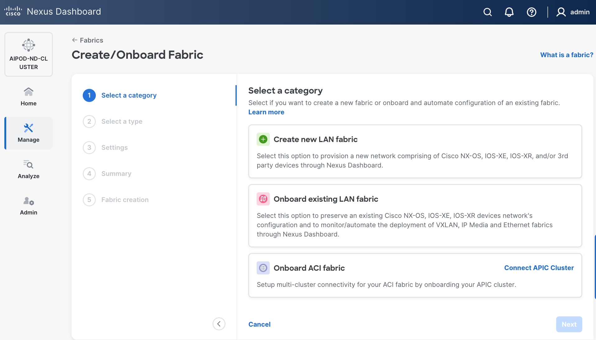
Step 3. Click Actions and select Create Fabric from the drop-down list.
Step 4. Select Create a new LAN fabric box. Click Next.
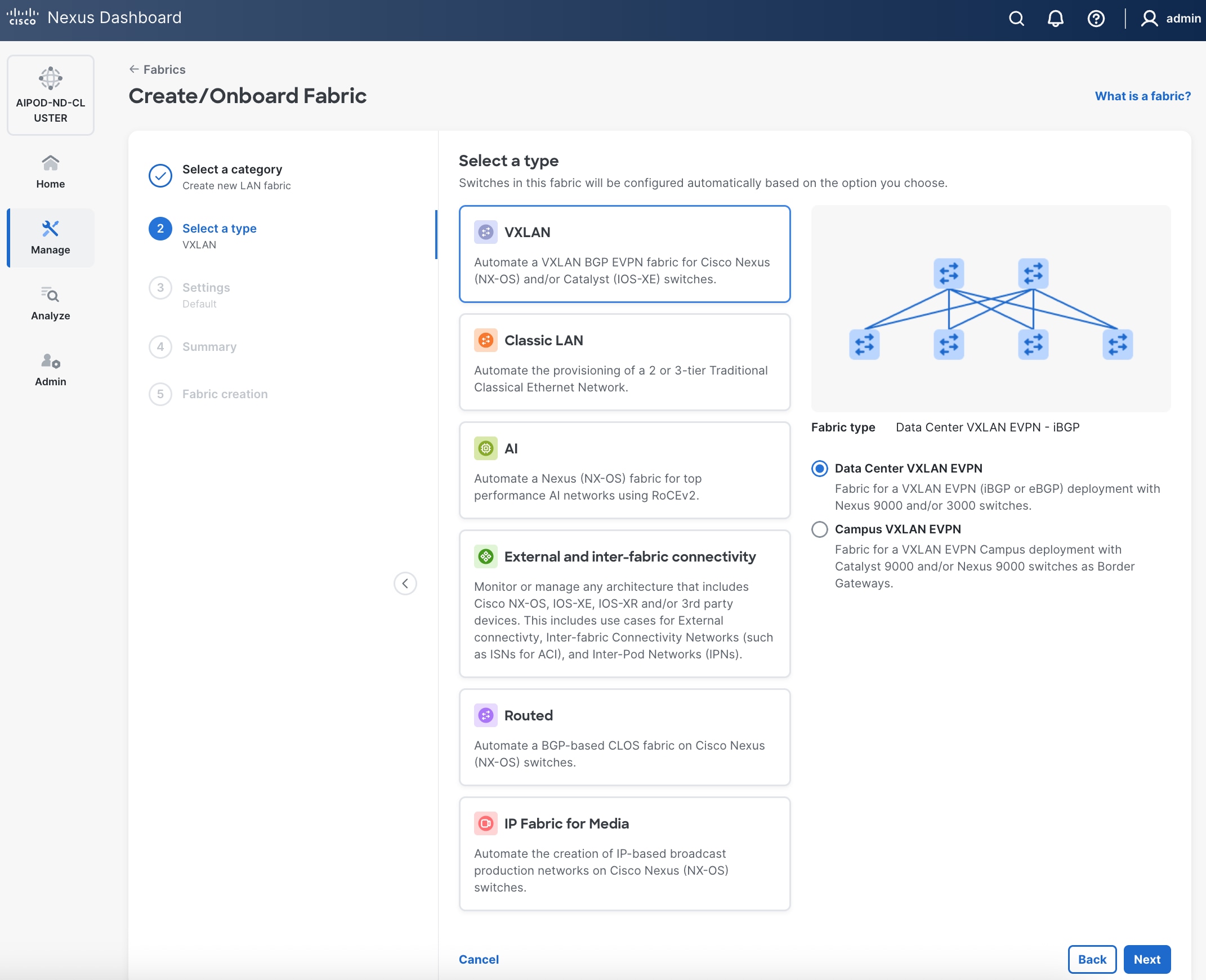
Step 5. Select VXLAN and radio button for Data Center VXLAN EVPN for the fabric type. Click Next.
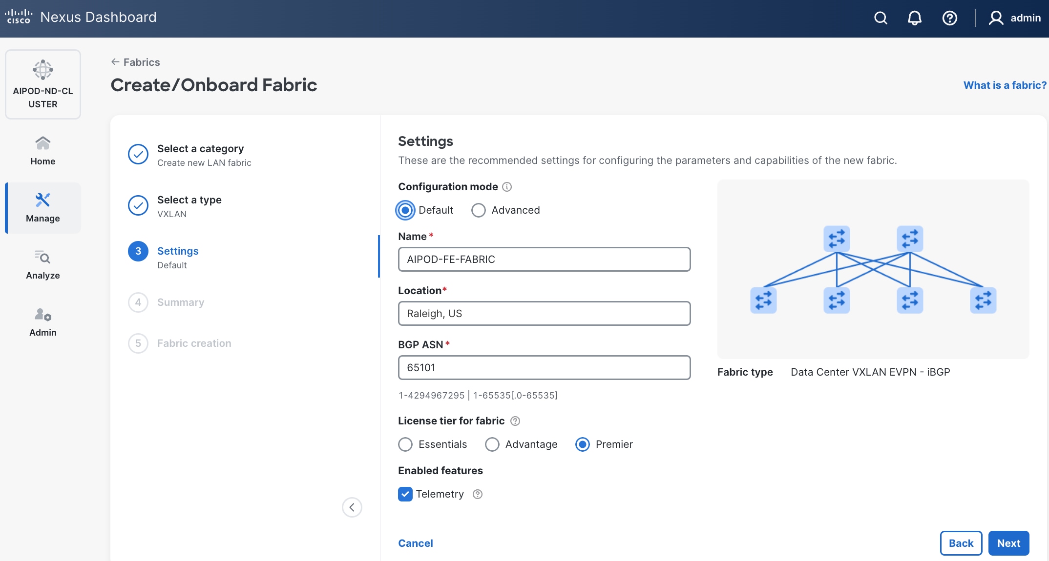
Step 6. For Configuration mode, keep the Default option. Specify Name, Location, and BGP ASN for fabric. Also select the Licensing tier for fabric from the options available. Premier is required for advanced network analytics and day 2 operations. Click the ? icon to see the features available in each tier.
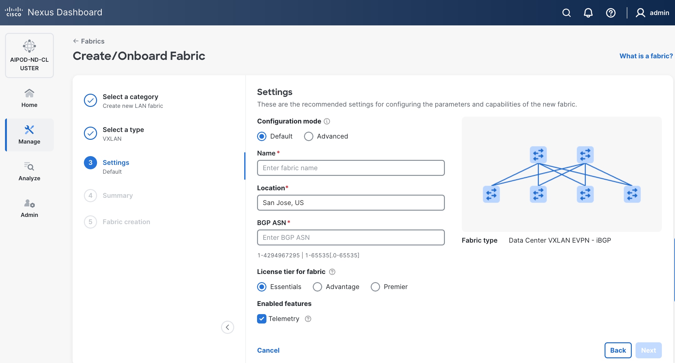
Step 7. Click Next.
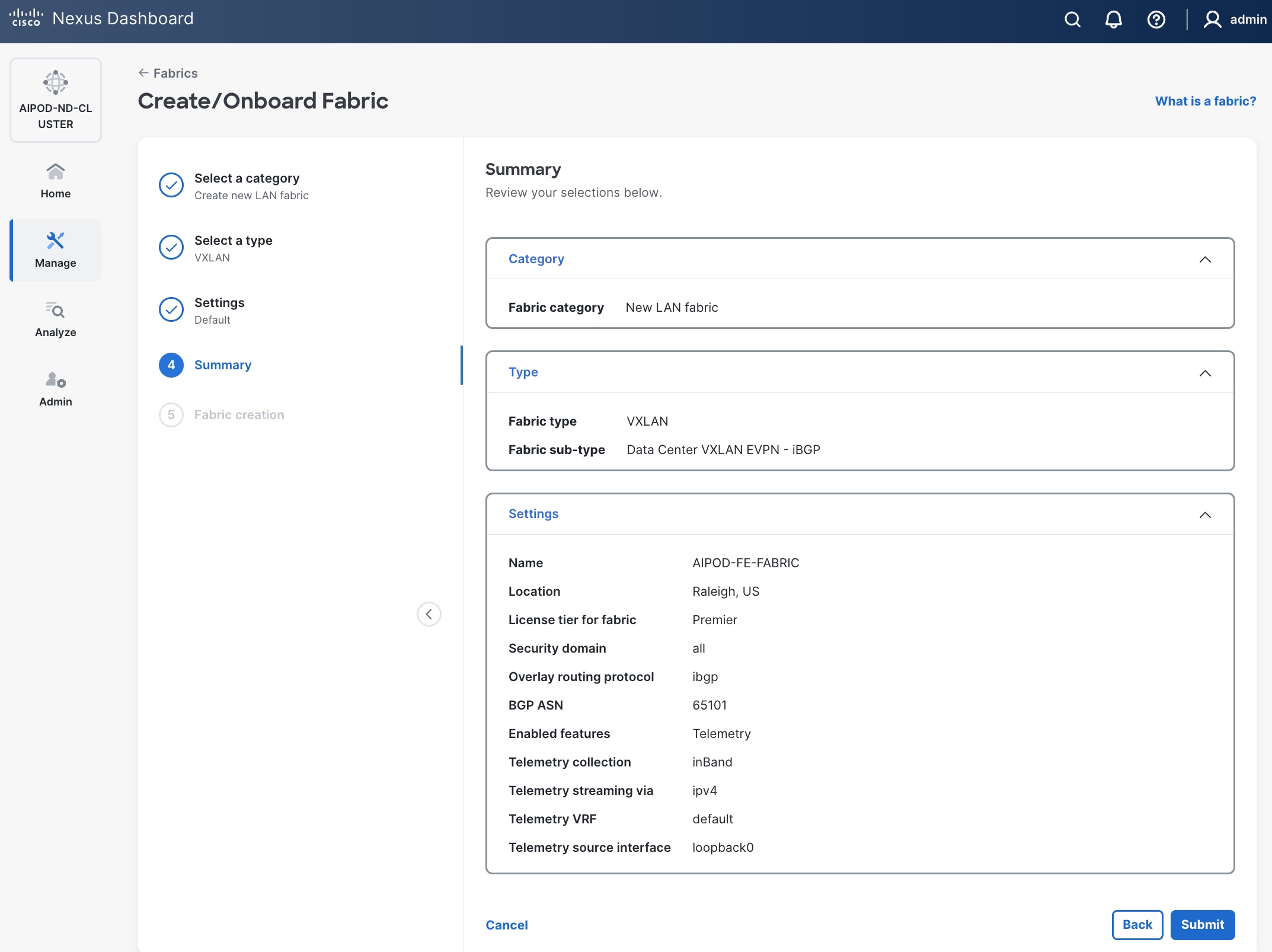
Step 8. In the Summary view, verify the settings and click Submit.
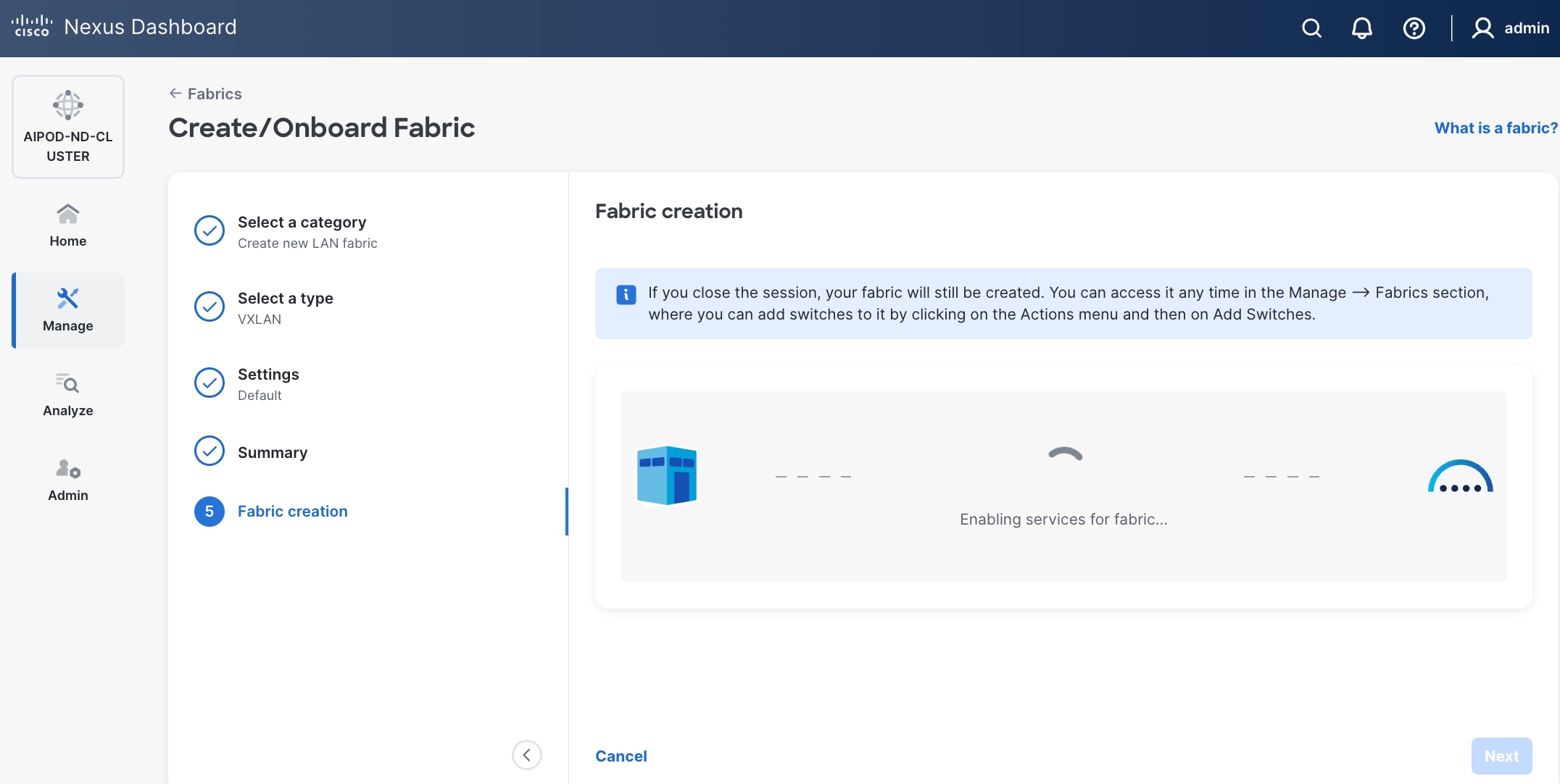
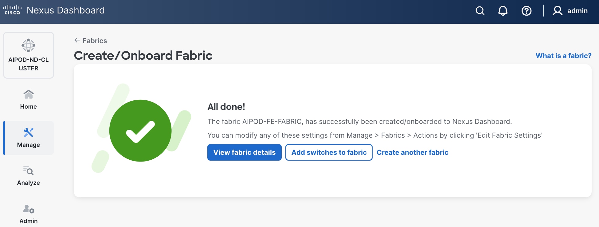
Step 9. When Fabric Creation completes, you should see the following:
Step 10. Select Manage > Fabrics on the left and then select the FE fabric. From the Actions drop-down list, select Edit fabric settings. Select the Fabric management tab and the Manageability tab underneath. Add the NTP Server IPs and the NTP Server VRF (management) and click Save.

Note: This screenshot and the following screenshot show BE fabric but are the same for the FE fabric.
Step 11. Select the Freeform tab and optionally enter the info shown in the screenshot modified for your timezone. Click Save.

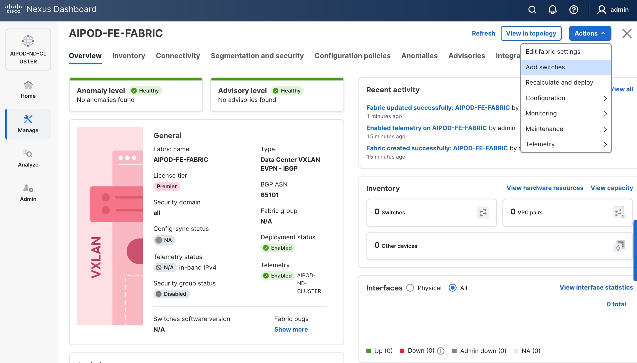
Step 12. If you want to add switches without a reload, click View fabric details. Select Fabric Management > Advanced tabs and scroll down to find the field for Add switches without Reload and change setting to enable. Click Save, followed by Got it in the pop-up window.
Step 13. From the Manage > Fabrics view, click the fabric name to add switches to the fabric.
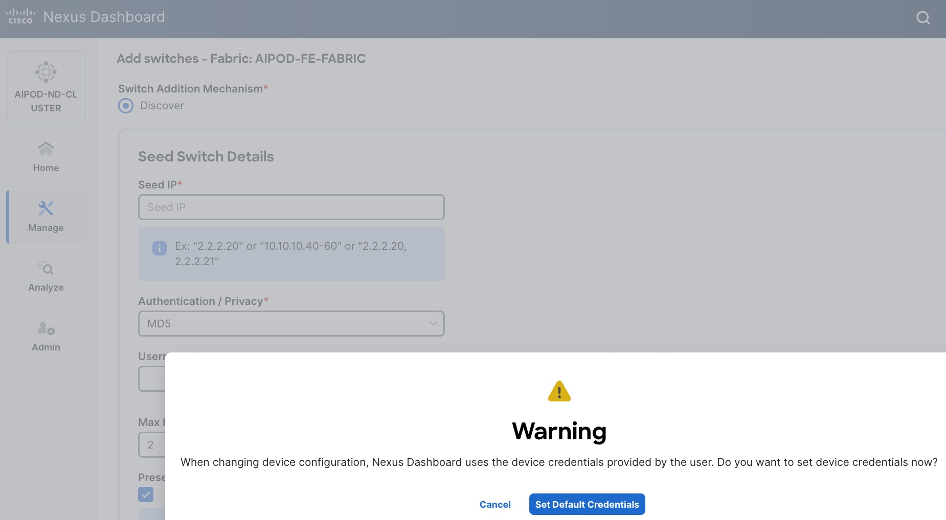
Step 14. Click Actions and select Add Switches from the drop-down list.
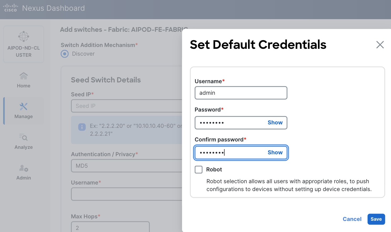
Step 15. In the pop-up window, click Set Default Credentials.
Step 16. Specify username and password. Click Save.
Step 17. Click OK.
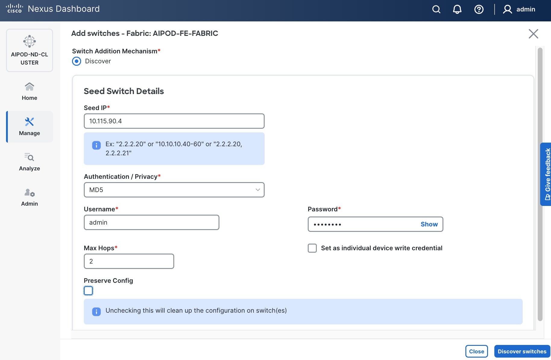
Step 18. Specify Seed IP, username and password. Adjust Max hops as needed. Click Discover Switches.
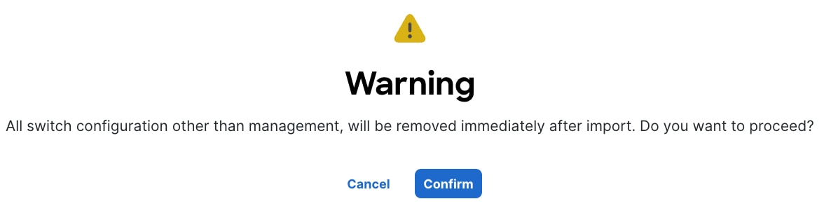
Step 19. Click Confirm in the pop-up Warning.
Step 20. Filter the discovered switch list as needed to view just the switches you want to add.
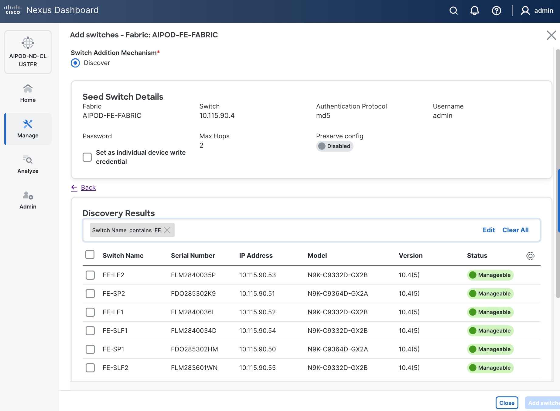
Step 21. Select all switches to be added. Click Add switches.
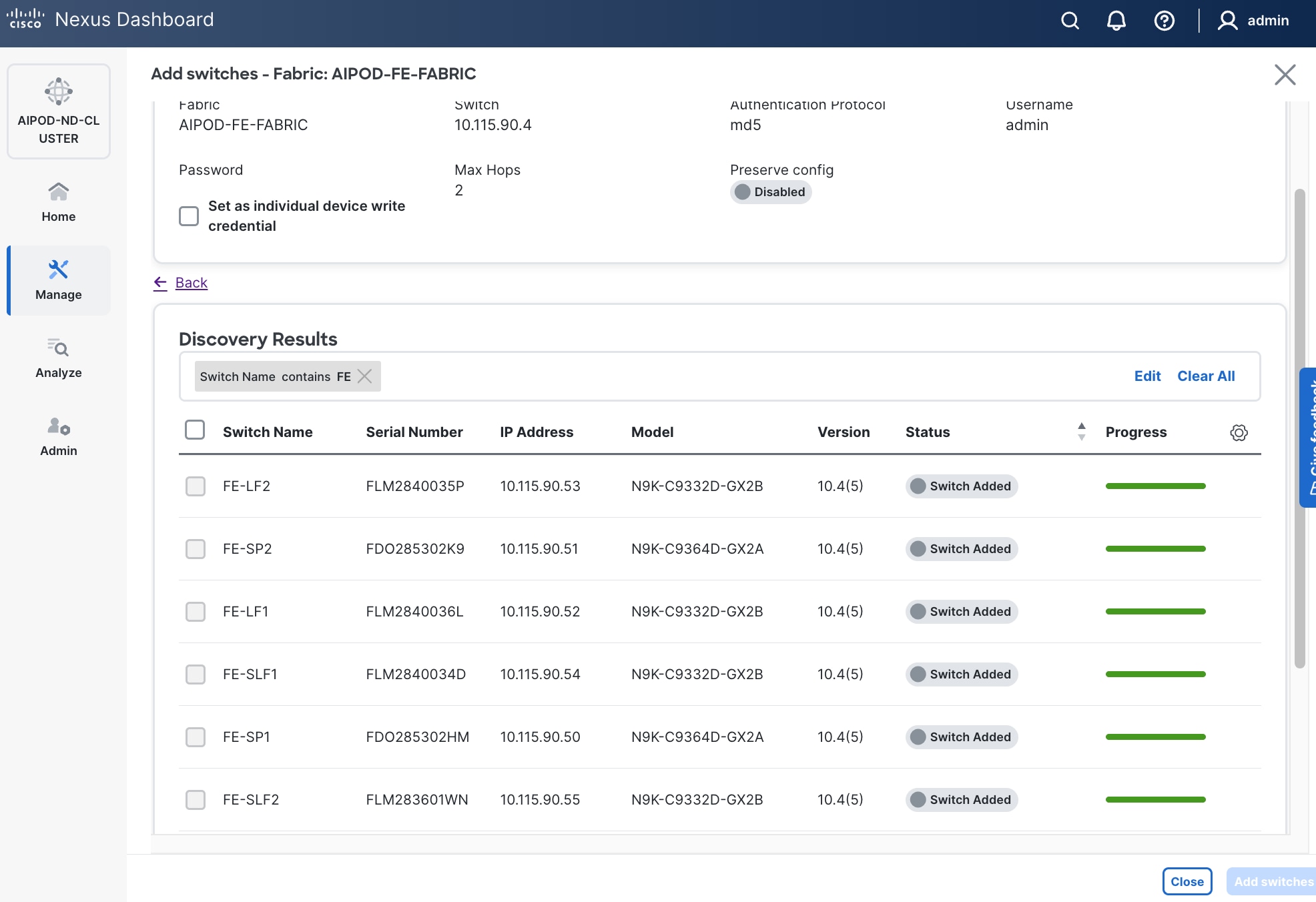
Step 22. Click Close when all switches have been added.
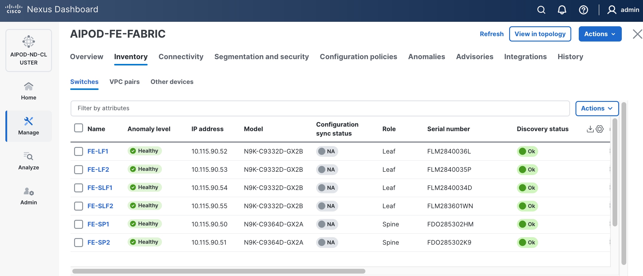
Step 23. From the Manage > Fabrics, select the fabric and click Inventory tab.
Step 24. For each switch in the list, verify Role is correct. To change the role, select the switch and then click the lower of the two Actions buttons and select Set role from the drop-down list.
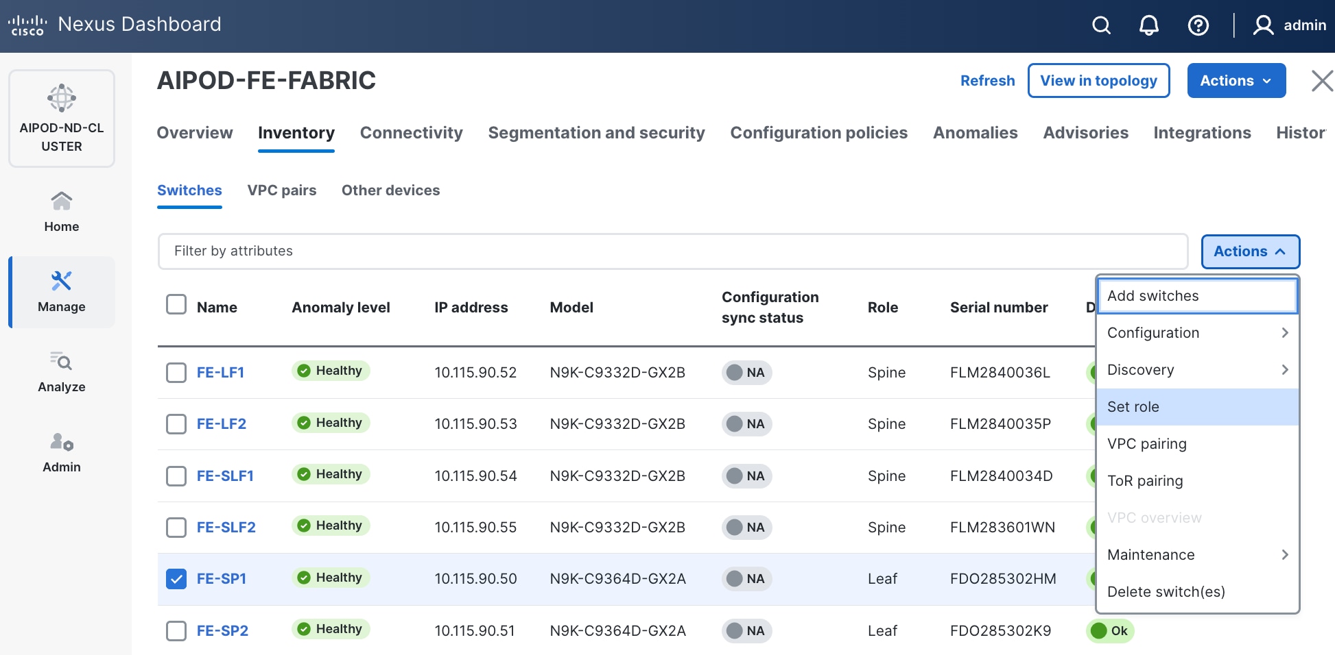
Step 25. In the Select Role pop-up window, select the correct role from the list and click Select.
Step 26. Click OK in the pop-up warning to perform "Recalculate and deploy" to complete the change.
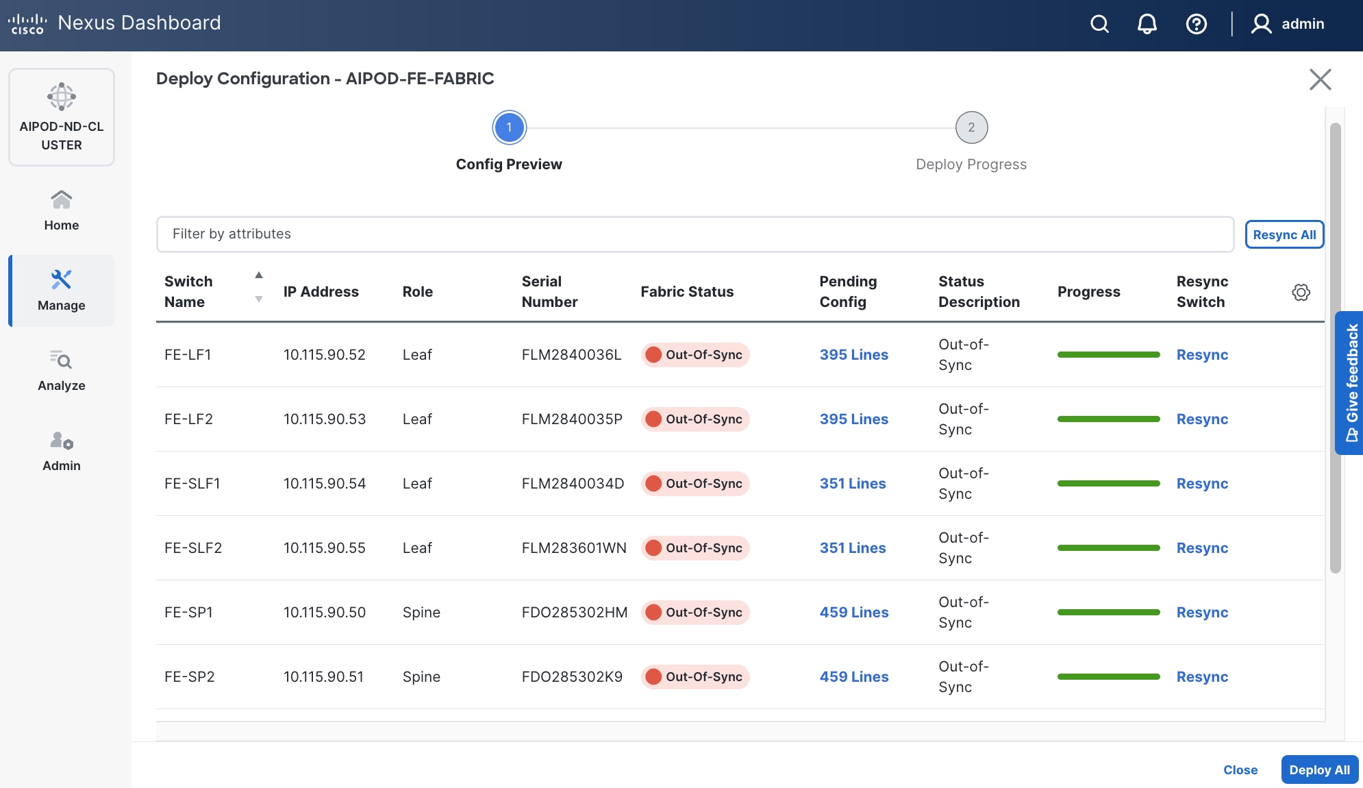
Step 27. Repeat these steps to select and confirm the role for all switches in the fabric.
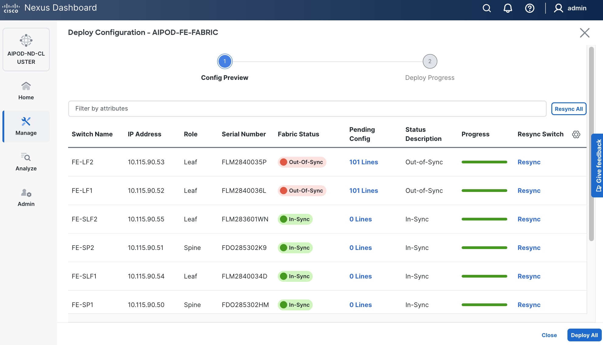
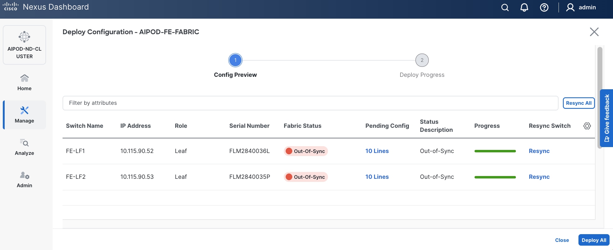
Step 28. Click the higher of the two Actions buttons and select Recalculate and deploy from the drop-down list. If it says one is already in progress, wait a few minutes and repeat the steps. You should see the Fabric as Out-of-sync with some Pending Config (lines of config) change.
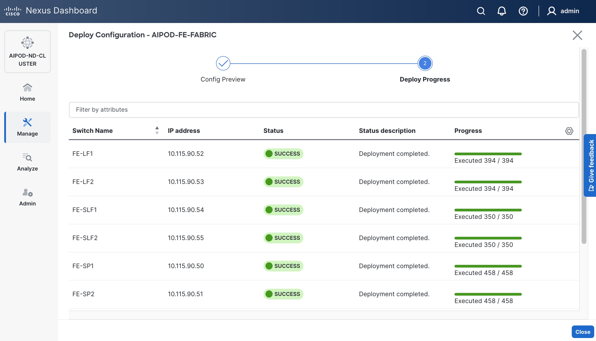
Step 29. Click Deploy All.
Step 30. Click Close.
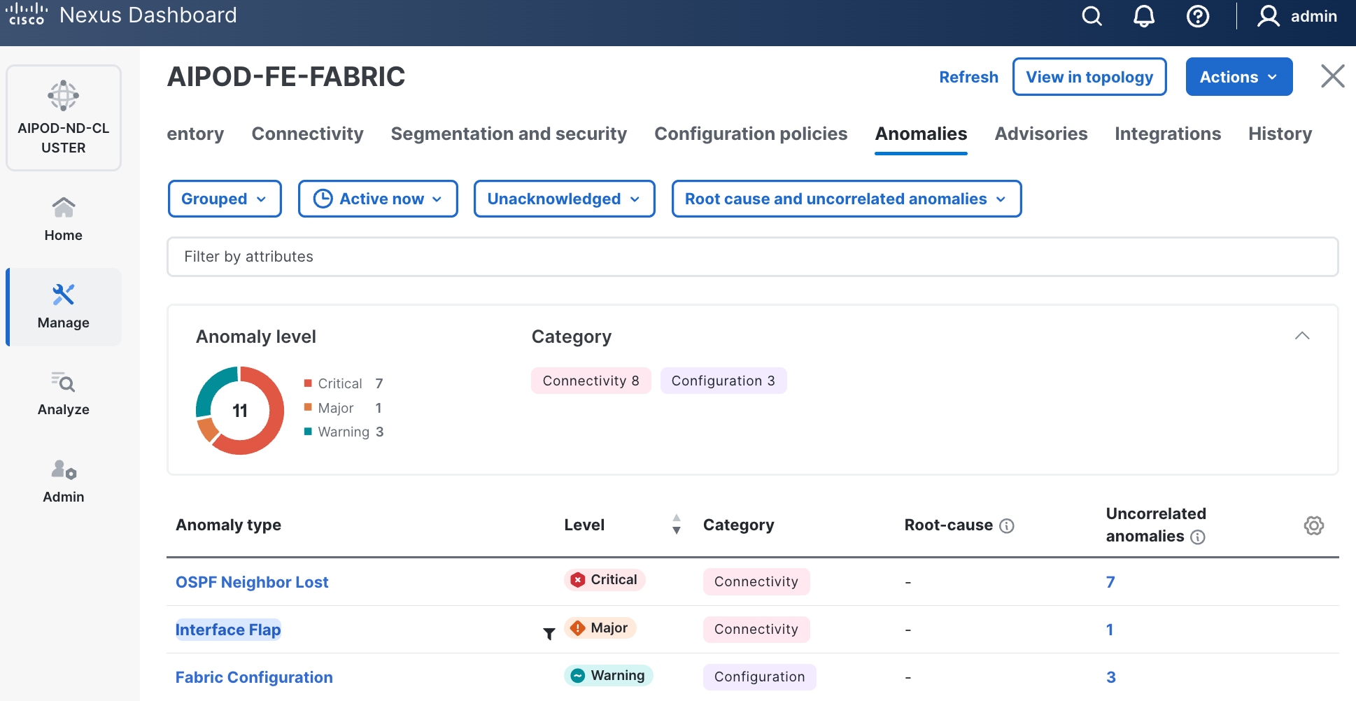
Step 31. ND will identify issues in hardware, connectivity, software and so on, reflected by the Anomaly level. To view the flagged anomalies, navigate to Anomalies in the top menu bar. Address each anomaly to prevent issues later, either by resolving them or acknowledging them.
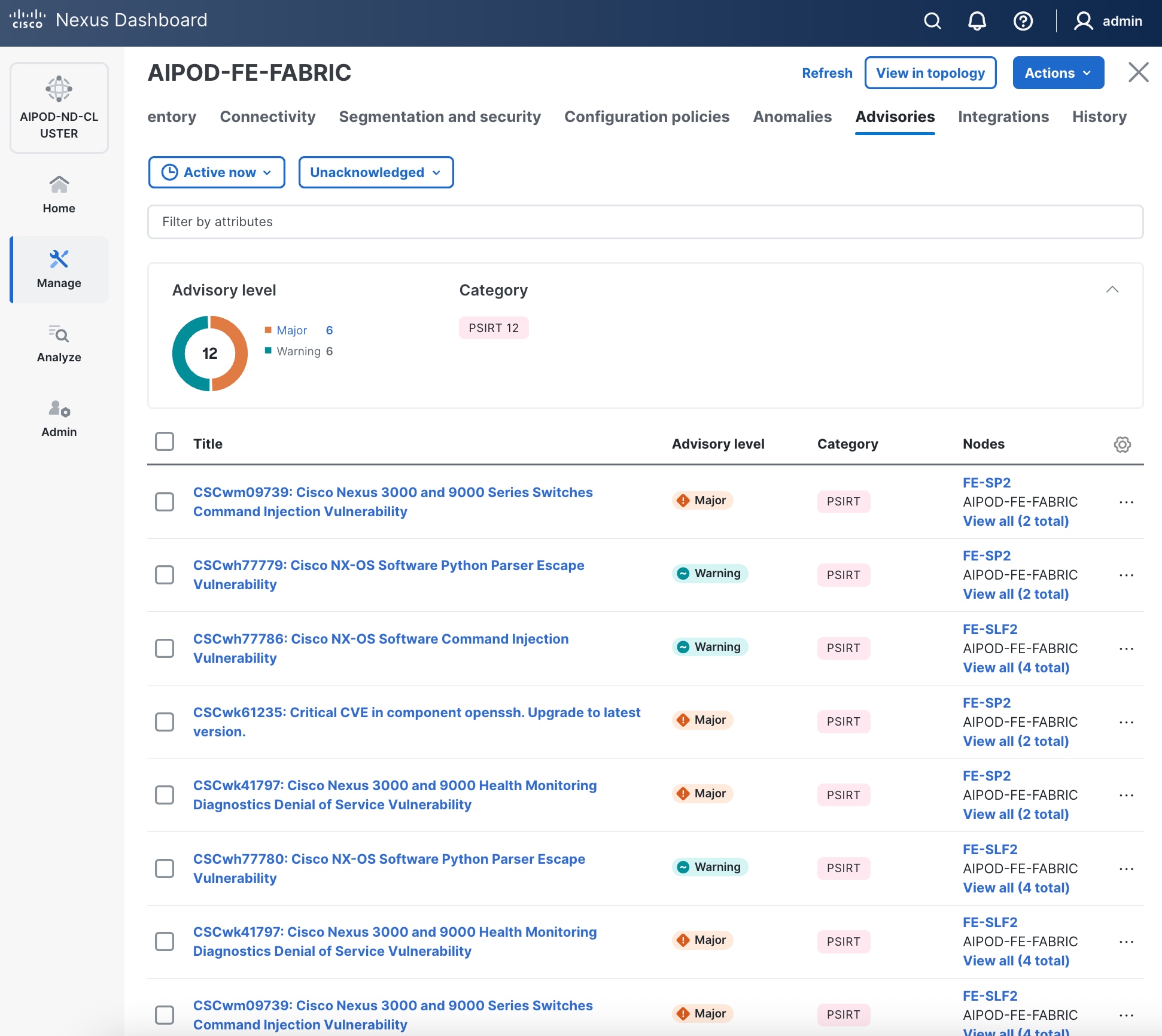
Step 32. Review the Advisories and resolve or acknowledge them.
Step 33. Evaluate and upgrade to Cisco recommended Nexus OS release.
Step 34. Now start attaching compute, storage and other end devices to the cluster.
Enable vPC Pairing on Compute/Management Leaf Switches in the FE Fabric
To enable vPC pairing on the compute/management in the FE fabric, follow the procedures below.
Procedure 1. Enable vPC pairing for compute/management leaf switches in the FE fabric
Step 1. Use a web browser to navigate to Nexus Dashboard. Use the management IP of any node in the ND cluster. Log in using admin account.
Step 2. From the left navigation menu, go to Manage > Fabrics.
Step 3. Select the FE fabric and click Inventory tab.
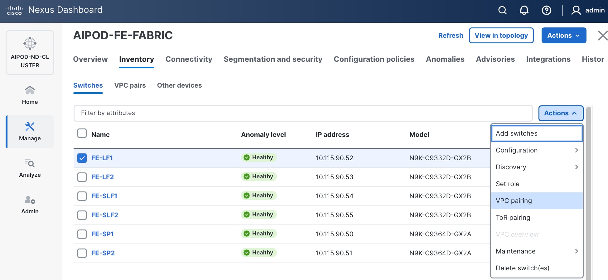
Step 4. To enable VPC pairing on the leaf switches that connect to UCS compute (GPU and management) nodes, select the first leaf switch in the leaf pair.
Step 5. Click the lower of the two Actions buttons and select VPC pairing from the drop-down list.
Step 6. Select the VPC peer switch for the first compute/management leaf. Enable Virtual Peerlink.
Step 7. Click Save.
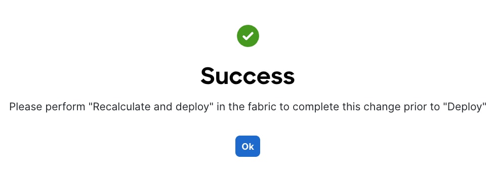
Step 8. Click OK in the Success pop-up window.
Step 9. Select the two leaf switches in the vPC pair that are now Out-of-sync from the configuration change. Click the higher of the two Actions buttons and select Recalculate and deploy from the drop-down list.
Step 10. Click Deploy All.
Step 11. When the configuration deployment completes successfully, click Close.
Step 12. In the Inventory tab, navigate to VPC pairs tab to see the newly created vPC pair.
Enable vPC Pairing on Storage Leaf Switches in the Frontend Fabric
To enable vPC pairing for the storage leaf switches in the FE fabric, follow the procedures below.
Procedure 1. Enable vPC pairing for storage leaf switches in the FE fabric
Step 1. Repeat the previous procedure to configure storage leaf switches in the FE fabric as vPC peers.
Step 2. In the Inventory tab, navigate to VPC pairs tab to see the newly created vPC pairs.
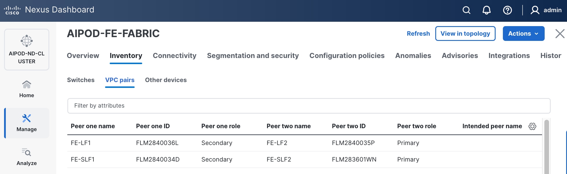
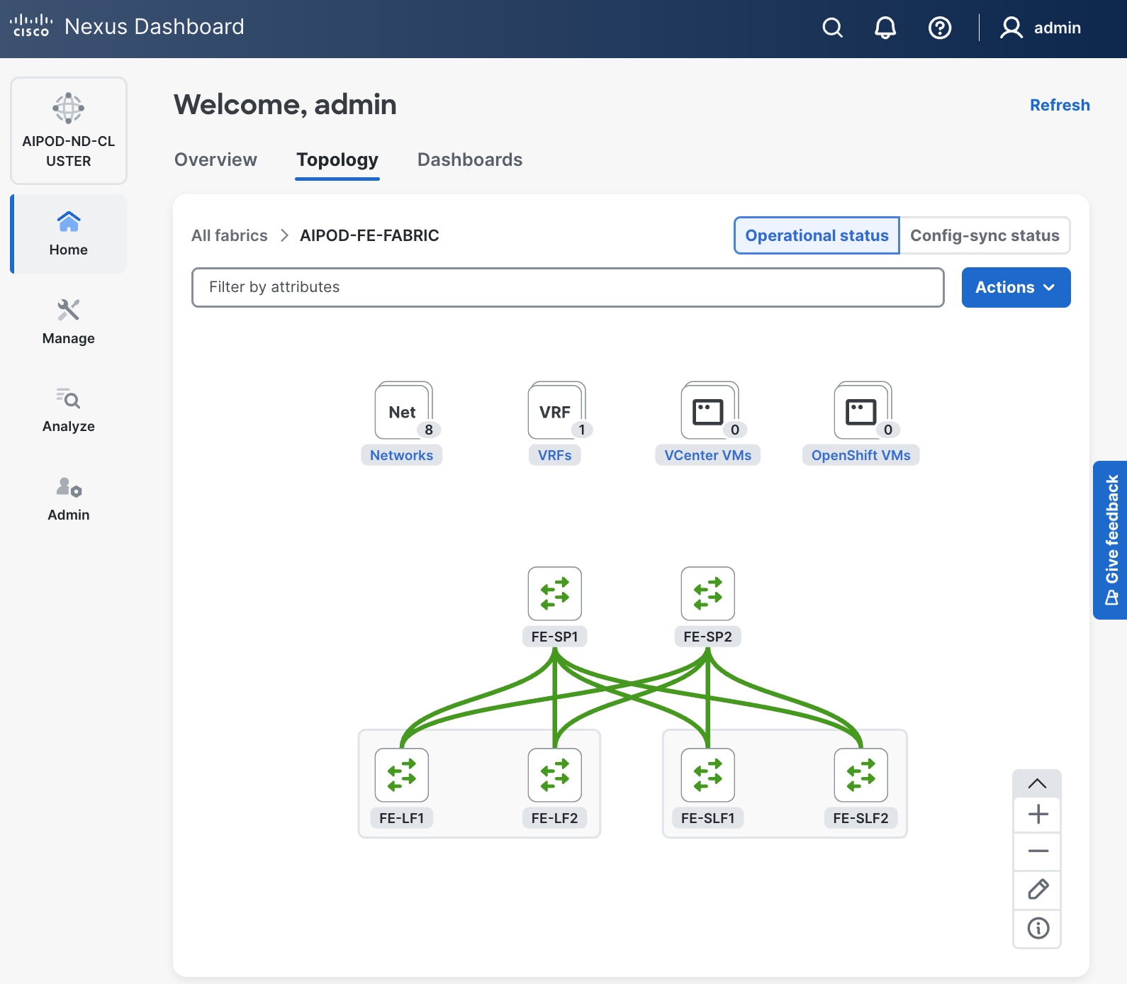
Step 3. From the left navigation menu, if you now go to Manage > Fabric and select the FE fabric and then the Topology tab, you should now see the 2 Leaf switch pairs grouped in a box, indicating they are vPC peers.
Enable Layer 2 Connectivity to Management UCS X-Direct from FE fabric
Table 8. Setup Parameters for FE Fabric: Layer 2 Connectivity to Management UCS X–Direct
| Parameter Type |
Parameter Name | Value |
Parameter Type |
| Leaf Switches |
FE-LF1, FE-LF2 |
|
| Management UCS |
UCS X-Direct with (-A, -B) uplinks; Both uplinks are dual-homed to FE-LF1 & FE-LF2 |
With multiple servers |
| Virtual Port Channel (vPC) |
To UCS X-Direct |
Management UCS-X Direct Chassis |
| vPC/PC1 - ID |
15 |
To UCS X-Direct: Side-A |
| vPC Pair |
FE-LF1, FE-LF2 |
|
| Ports |
1/5, 1/7 |
FI-A: Ports 1/1-4 (PC-11) |
| vPC/PC2 – ID |
16 |
To UCS X-Direct: Side-B |
| Ports |
1/6, 1/8 |
FI-B: Ports 1/1-4 (PC-12) |
To enable Layer 2 connectivity to management Cisco UCS X-Series Direct chassis from the FE fabric, follow the procedures below. You will be configuring two vPCs to the management Cisco UCS X-Series Direct, one for -A side and another for -B side. Each vPC will use multiple ports on each compute leaf switch pair to connect to -A and -B uplinks on Cisco UCS X-Series Direct chassis.
Procedure 1. Deploy first vPC to Management UCS X-Series Direct
Step 1. Use a web browser to navigate to Nexus Dashboard. Use the management IP of any node in the ND cluster. Log in using admin account.
Step 2. From the left navigation menu, go to Manage > Fabrics.
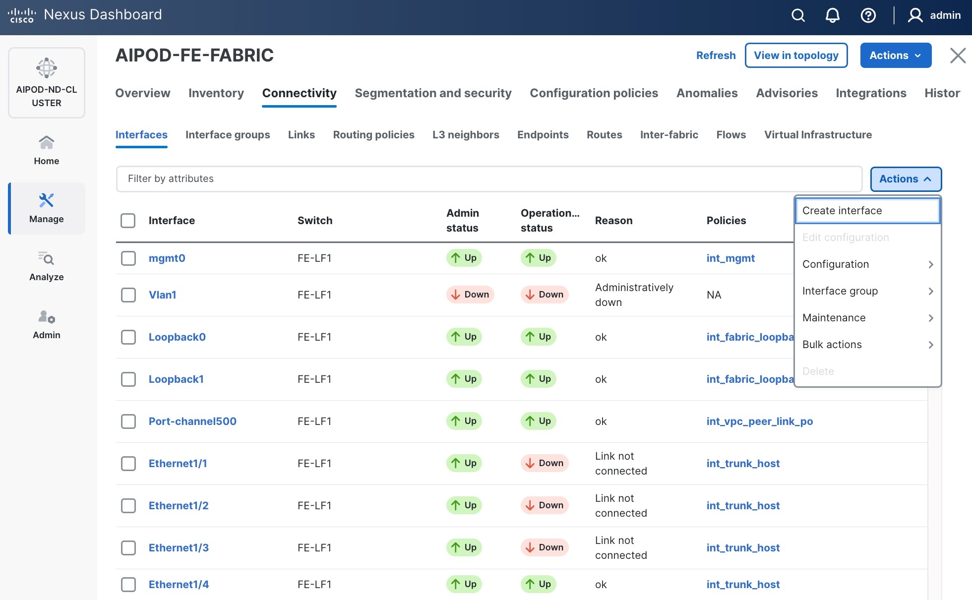
Step 3. Select the FE fabric and navigate to Connectivity > Interfaces tab.
Step 4. Click the lower of the two Actions buttons and select Create interface.

Step 5. In the Create interface window:
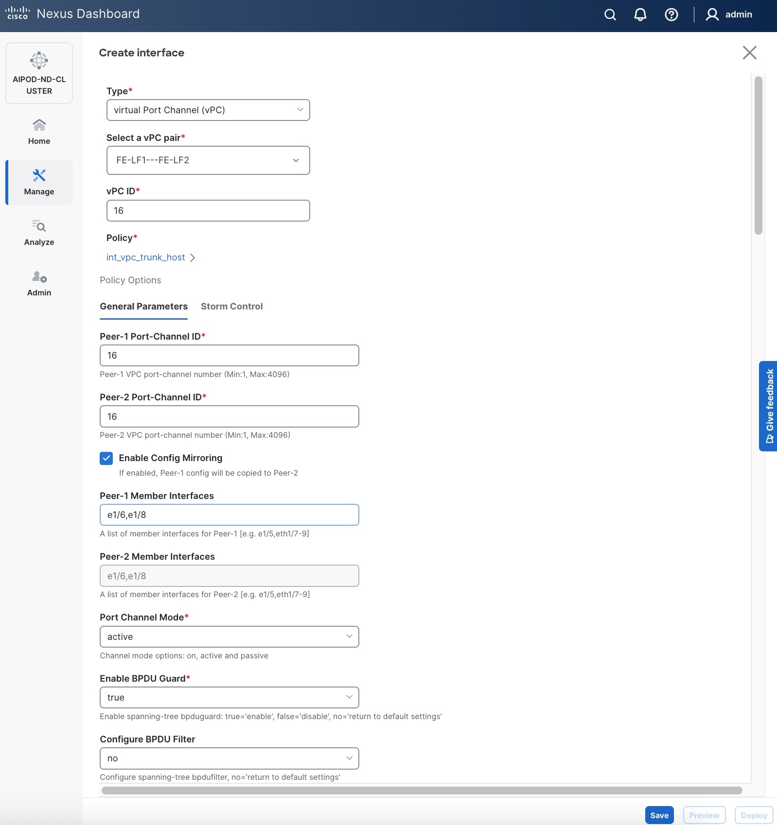
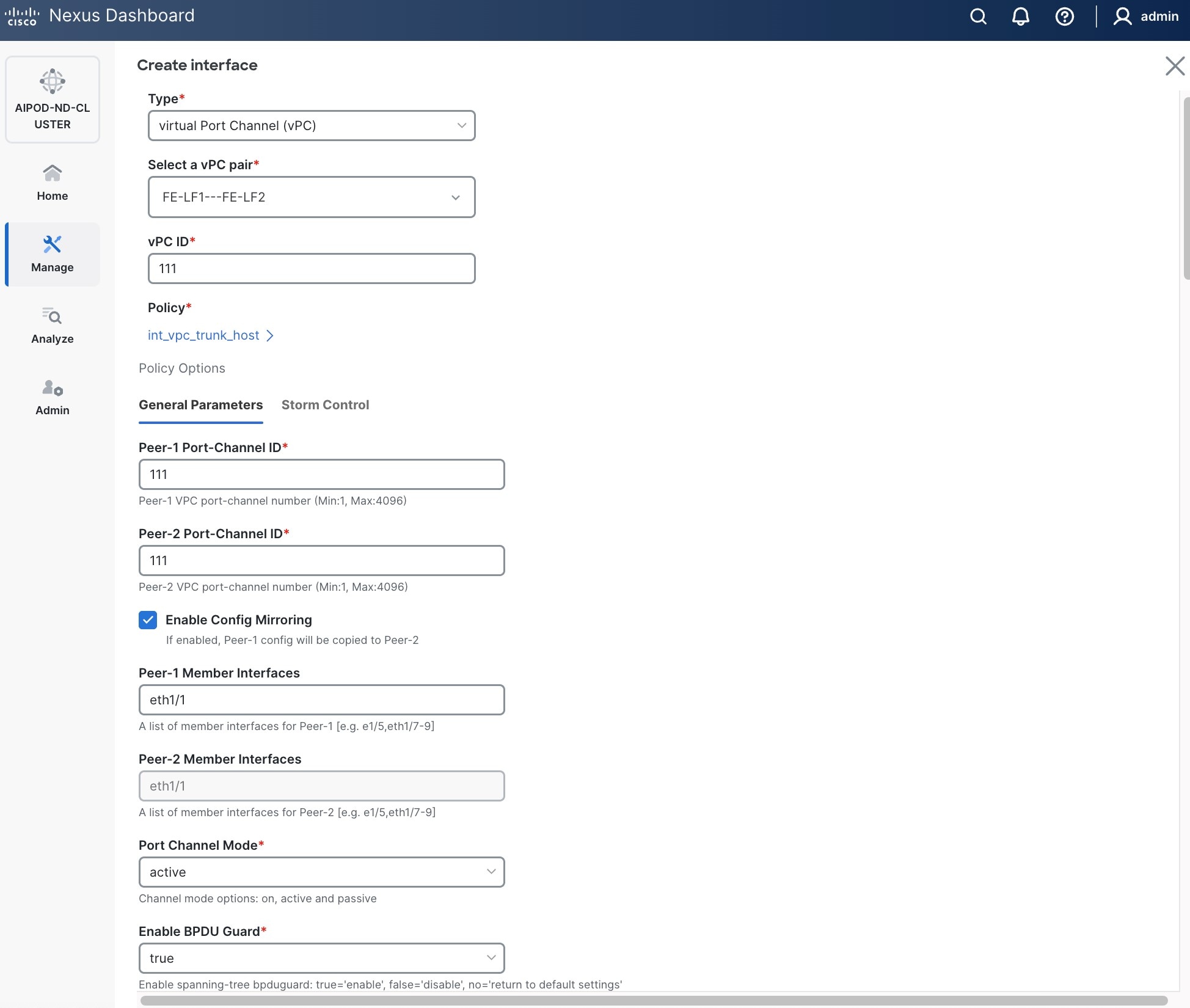
● Specify the TypeType of interface as virtual Port Channel (vPC)virtual Port Channel (vPC) from the drop-down list.
● For the Select a vPC pairSelect a vPC pair, select the compute leaf switch vPC pair from the drop-down list.
● Specify a vPC IDvPC ID for the firstfirst vPC to the UCS X-Direct (-A side-A side). Port Channel IDs from each switch to the first UCS node should match the vPC ID (see screenshot below).
● Leave the Policy as int_vpc_trunk_host.
● EnableEnable checkbox for Config MirroringConfig Mirroring to configure both vPC peer switches identically.
● Specify Peer-1 Member InterfacesPeer-1 Member Interfaces that connects to first UCS node.
● Leave other fields as is.
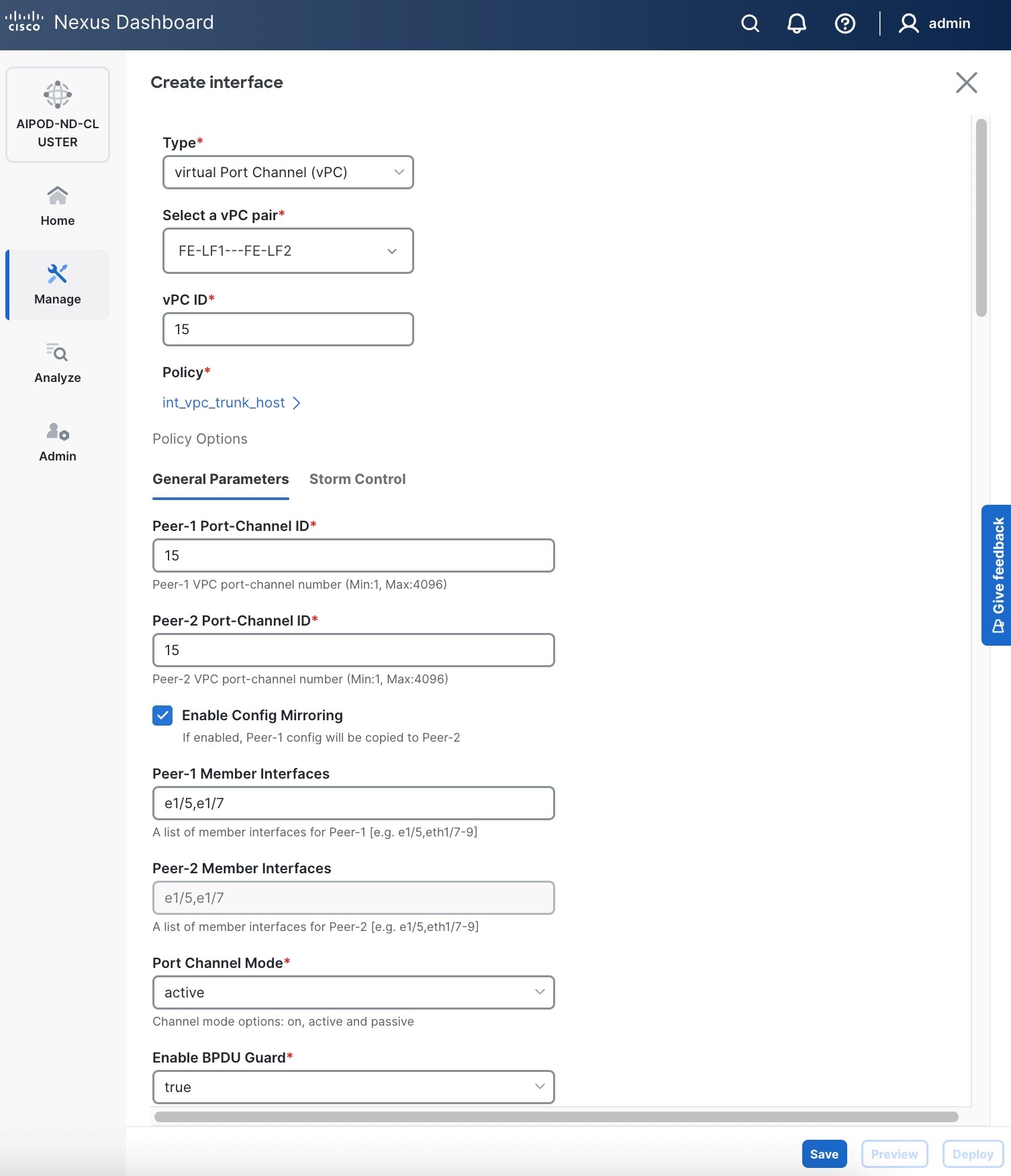
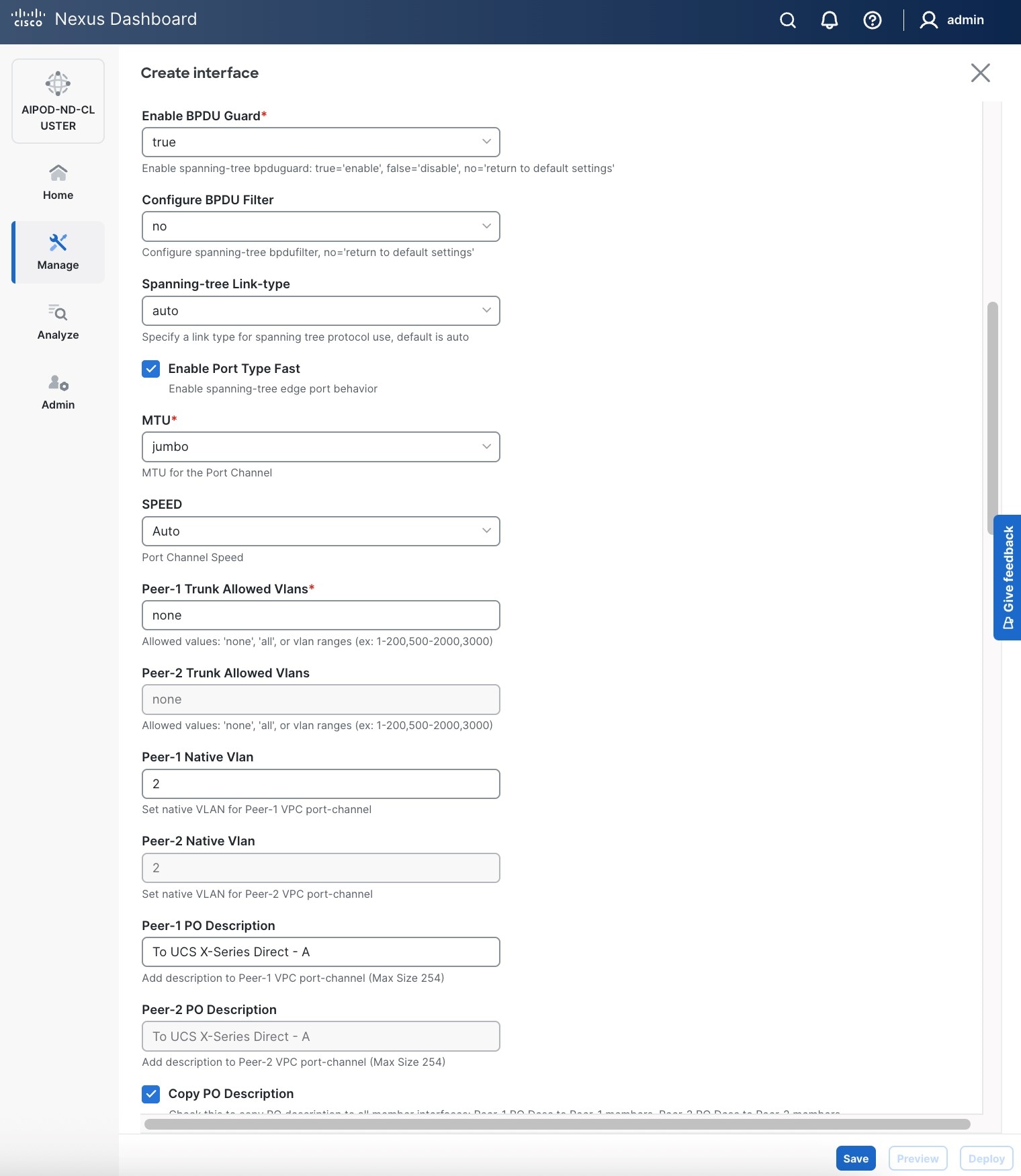
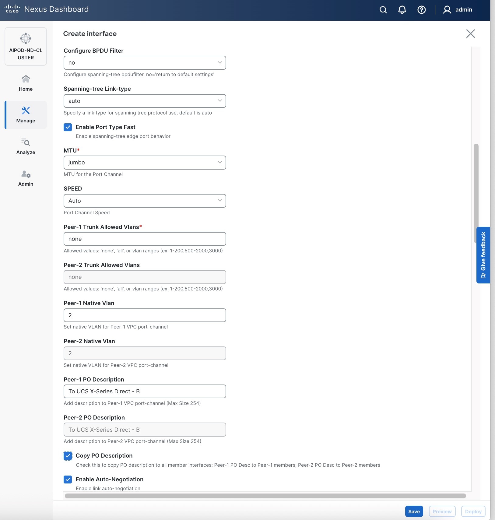
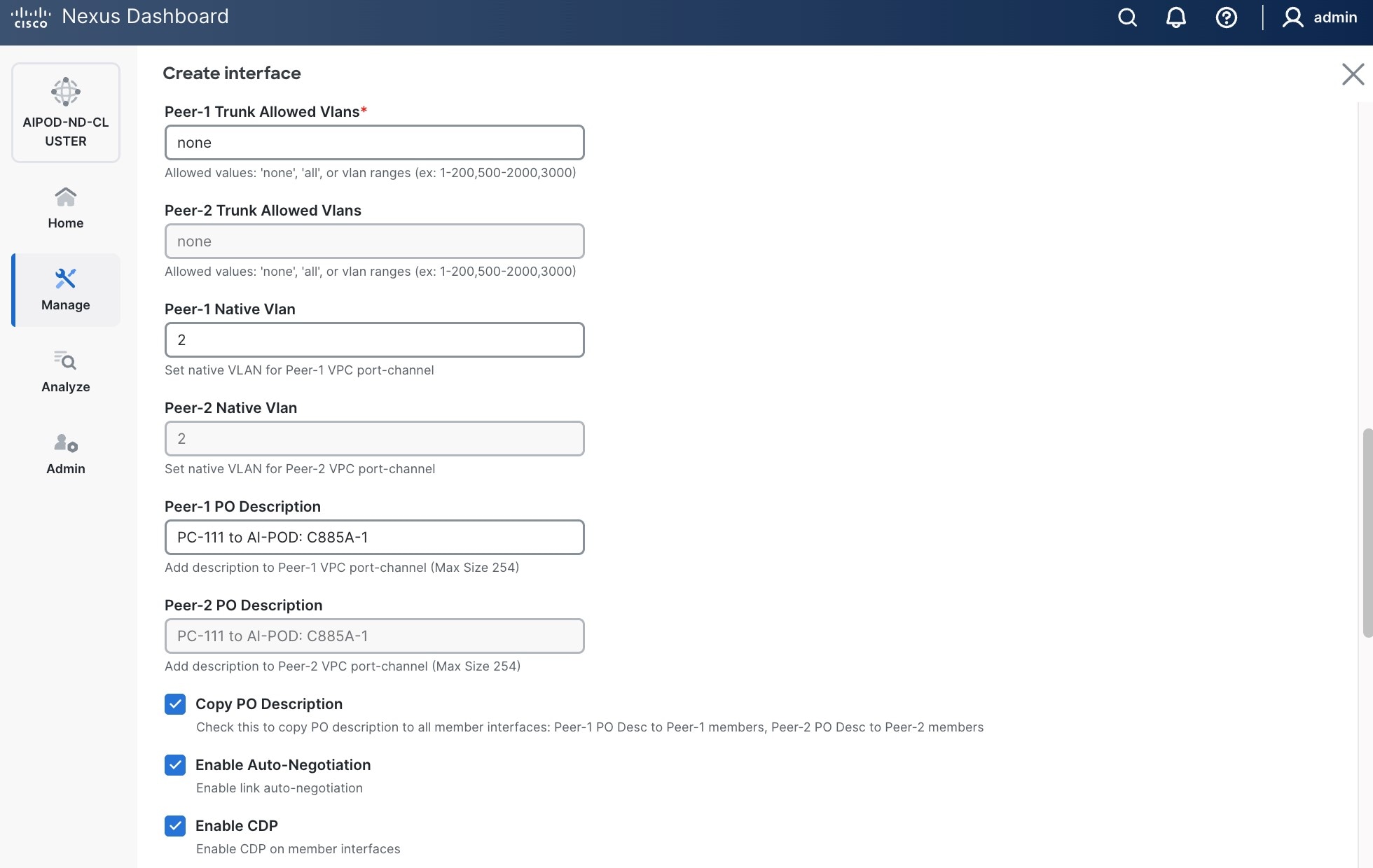
● Scroll down and fill remaining fields: Native VLANNative VLAN, Peer-1 PO Description, Peer-1 PO Description, and select the checkbox for Copy PO Description Copy PO Description to copy the description to second vPC peer’s Port Channel.
Step 6. Click Save.
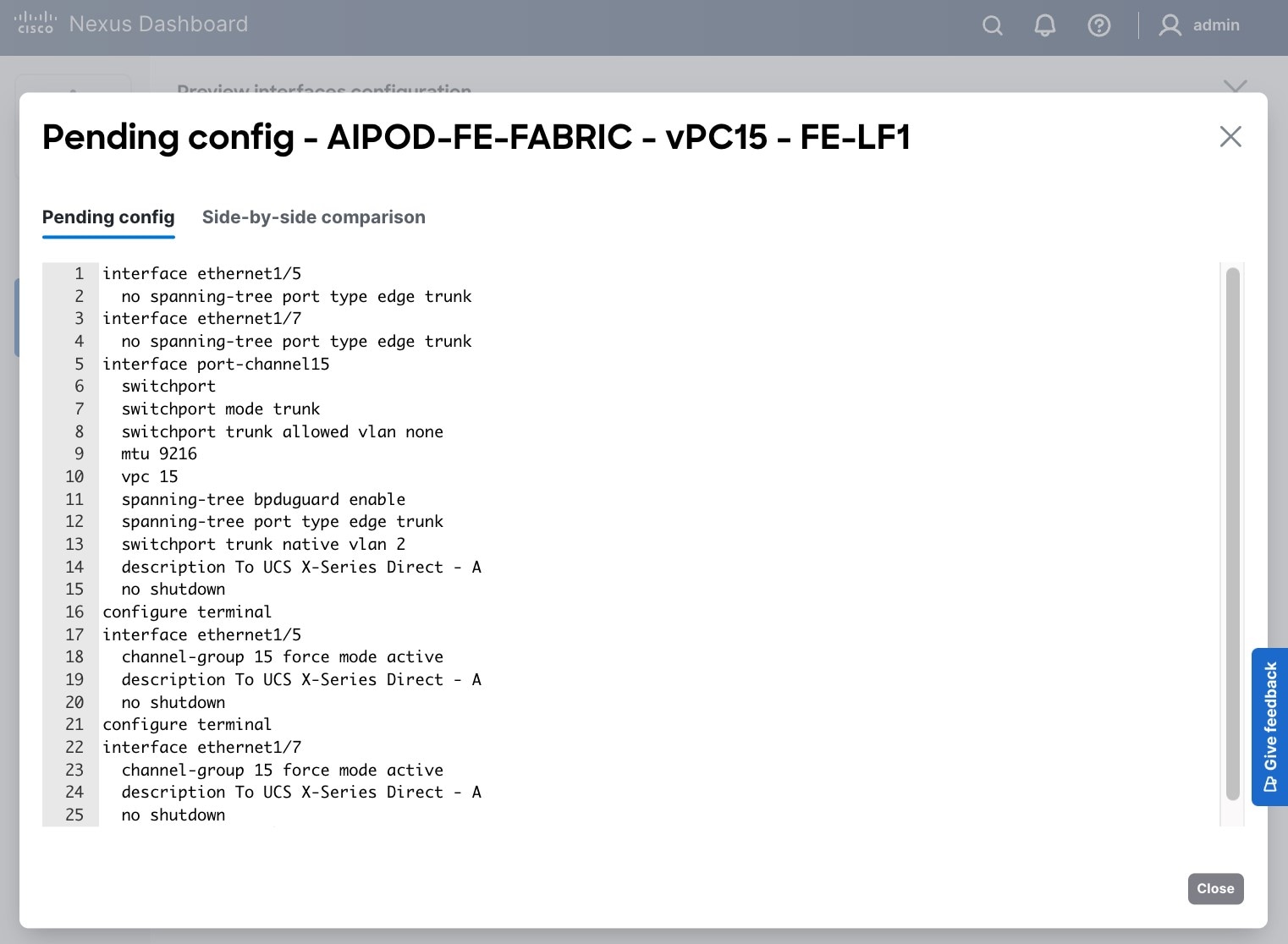
Step 7. Click Preview.
Step 8. Click Close, then click Cancel.
Step 9. Click Deploy. The Pending Config is the configuration shown in a previous step.
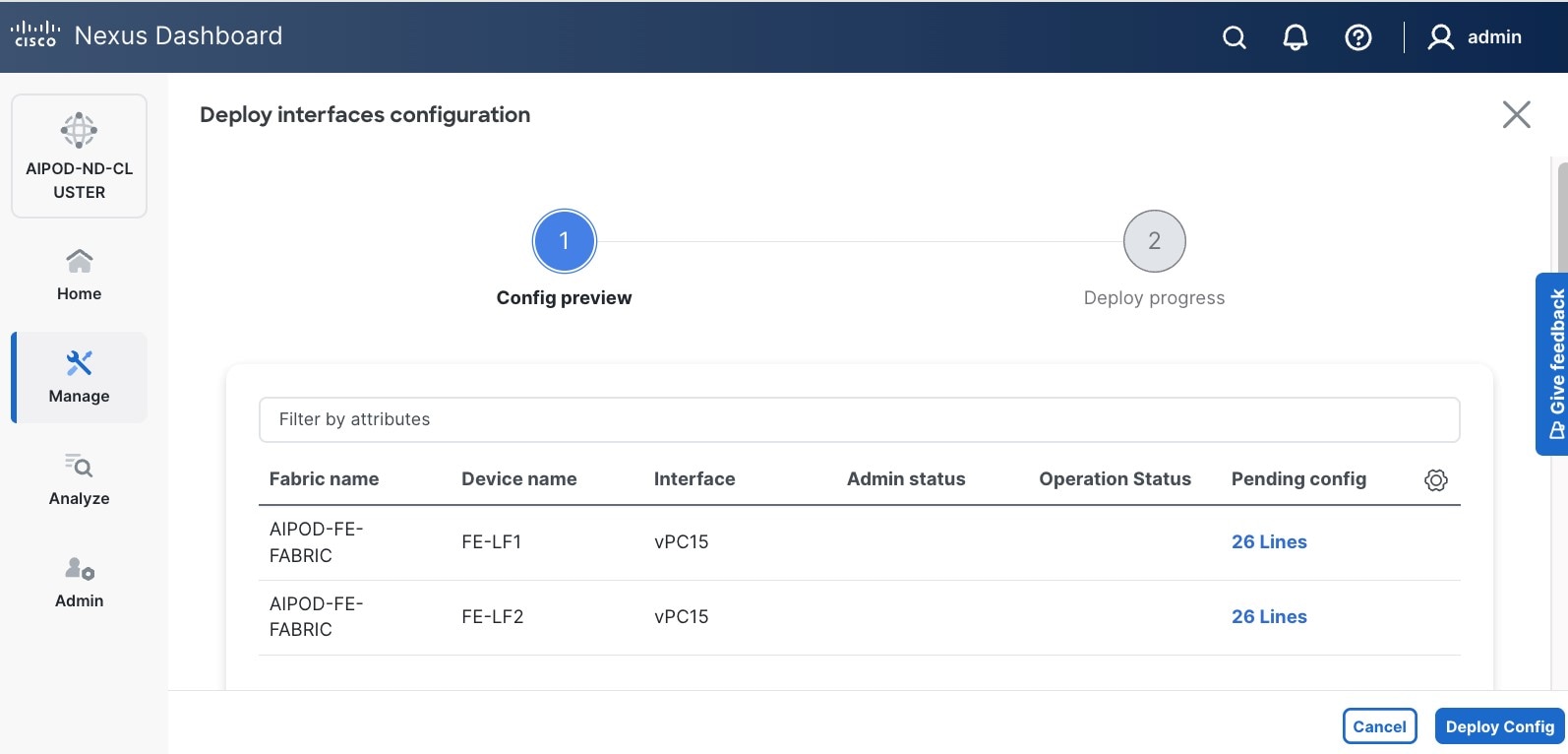
Step 10. Click Deploy Config.
Step 11. Verify that all the interfaces and port-channels are up on each switch in the vPC leaf pair that connects to the UCS X-Series Direct (-A side). It may take a few minutes for the vPC to go from Not discovered to consistent state.
Procedure 2. Deploy second vPC to Management UCS X-Direct
Step 1. Repeat the previous procedure for the second vPC to UCS X-Series Direct (-B side).
Step 2. Click Save.
Step 3. Click Deploy, followed by Deploy Config.
Step 4. Verify that all the interfaces and port-channels are up on each switch in the vPC leaf pair that connects to the UCS X-Series Direct (-B side). It may take a few minutes for the vPC to go from Not discovered to consistent state.
Enable Layer 2 Connectivity to UCS GPU Nodes from FE Fabric
To enable layer 2 connectivity to UCS GPU nodes, you will be configuring four vPCs, one per UCS C885A node. Each vPC will use one port on each switch in the compute leaf pair to connect to the UCS node.
Table 9. Setup Parameters for FE Fabric: Layer 2 Connectivity to UCS GPU Nodes
| Parameter Type |
Parameter Name | Value |
Parameter Type |
| Leaf Switches |
FE-LF1, FE-LF2 |
|
| UCS Nodes |
4 x UCS C885A GPU Nodes, each dual-homed to FE-LF1 & FE-LF2 |
|
| Virtual Port Channel (vPC) |
To UCS C885As |
UCS GPU Nodes |
| vPC/PC1 - ID |
111 |
|
| vPC Pair |
FE-LF1, FE-LF2 |
|
| Ports |
1/1 |
On each Leaf switch |
| vPC/PC2 – ID |
112 |
|
| vPC Pair |
FE-LF1, FE-LF2 |
|
| Ports |
1/2 |
On each Leaf switch |
| vPC/PC3 - ID |
113 |
|
| vPC Pair |
FE-LF1, FE-LF2 |
|
| Ports |
1/3 |
On each Leaf switch |
| vPC/PC4 – ID |
114 |
|
| vPC Pair |
FE-LF1, FE-LF2 |
|
| Ports |
1/4 |
On each Leaf switch |
To enable Layer 2 connectivity to UCS C885A GPU nodes from the FE fabric, follow the procedures below.
Procedure 1. Deploy first vPC to first UCS C885A GPU node
Step 1. Use a web browser to navigate to Nexus Dashboard. Use the management IP of any node in the ND cluster. Log in using admin account.
Step 2. From the left navigation menu, go to Manage > Fabrics.
Step 3. Select the FE fabric and navigate to Connectivity > Interfaces tab.
Step 4. Click the lower of the two Actions buttons and select Create interface.
Step 5. In the Create interface window:
● Specify the TypeType of interface as virtual Port Channel (vPC)virtual Port Channel (vPC) from the drop-down list.
● For the Select a vPC pairSelect a vPC pair, select the compute leaf switch VPC pair from the drop-down list.
● Specify a vPC IDvPC ID for the vPC to the first first UCS GPU node. Peer-1 and Peer-2 Port-Channel ID should match that of the vPC ID.
● Leave the Policy as int_vpc_trunk_host.
● Enable checkbox for Config Mirroring.
● Specify Peer-1 Member InterfacesPeer-1 Member Interfaces that connects to first UCS node.
● Specify Peer-1 Native Vlan.
● Specify Peer-1 PO Description.
● EnableEnable the checkbox for Copy PO DescriptionCopy PO Description to copy PO description to all member interfaces.
Step 6. Additional configuration changes can be made later as needed. Click Save.
Step 7. Click Preview to view the Pending config changes.
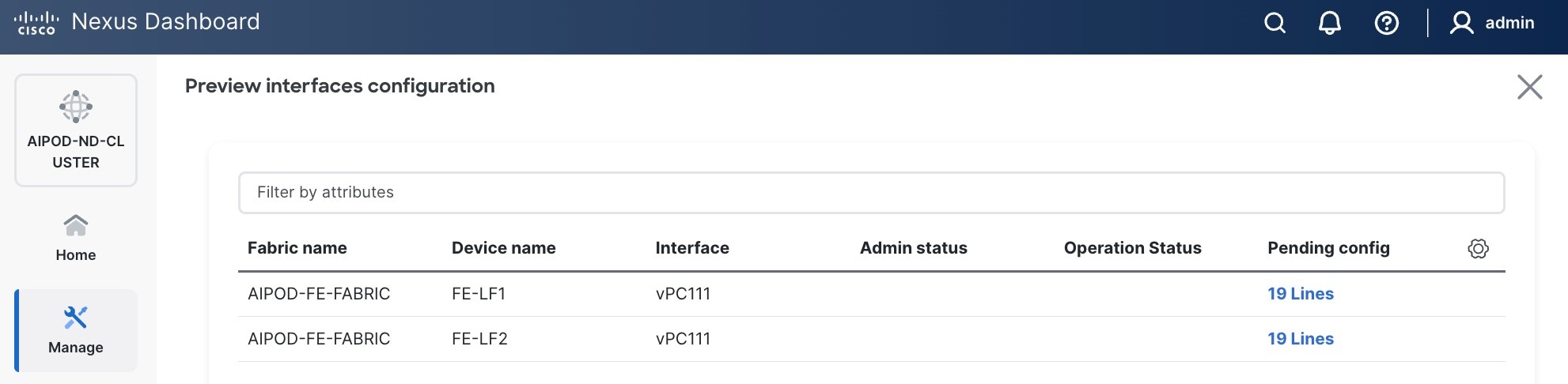
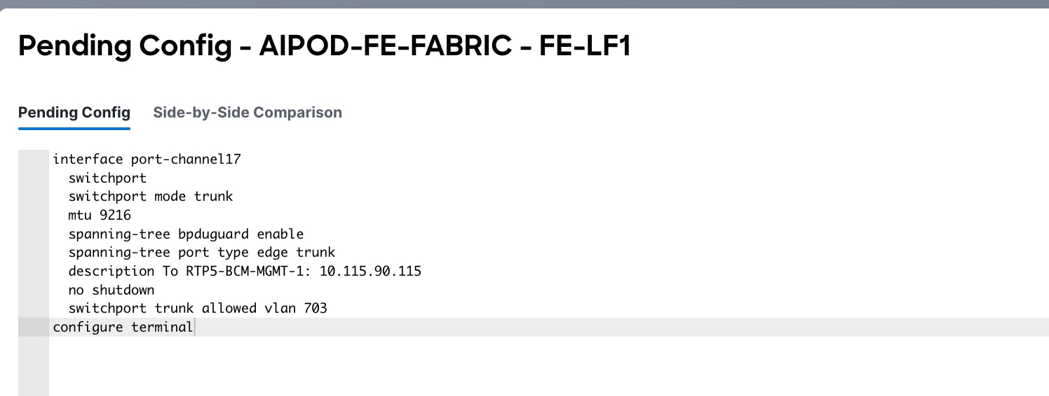
Step 8. Click the Pending Config for each switch to see the configuration.
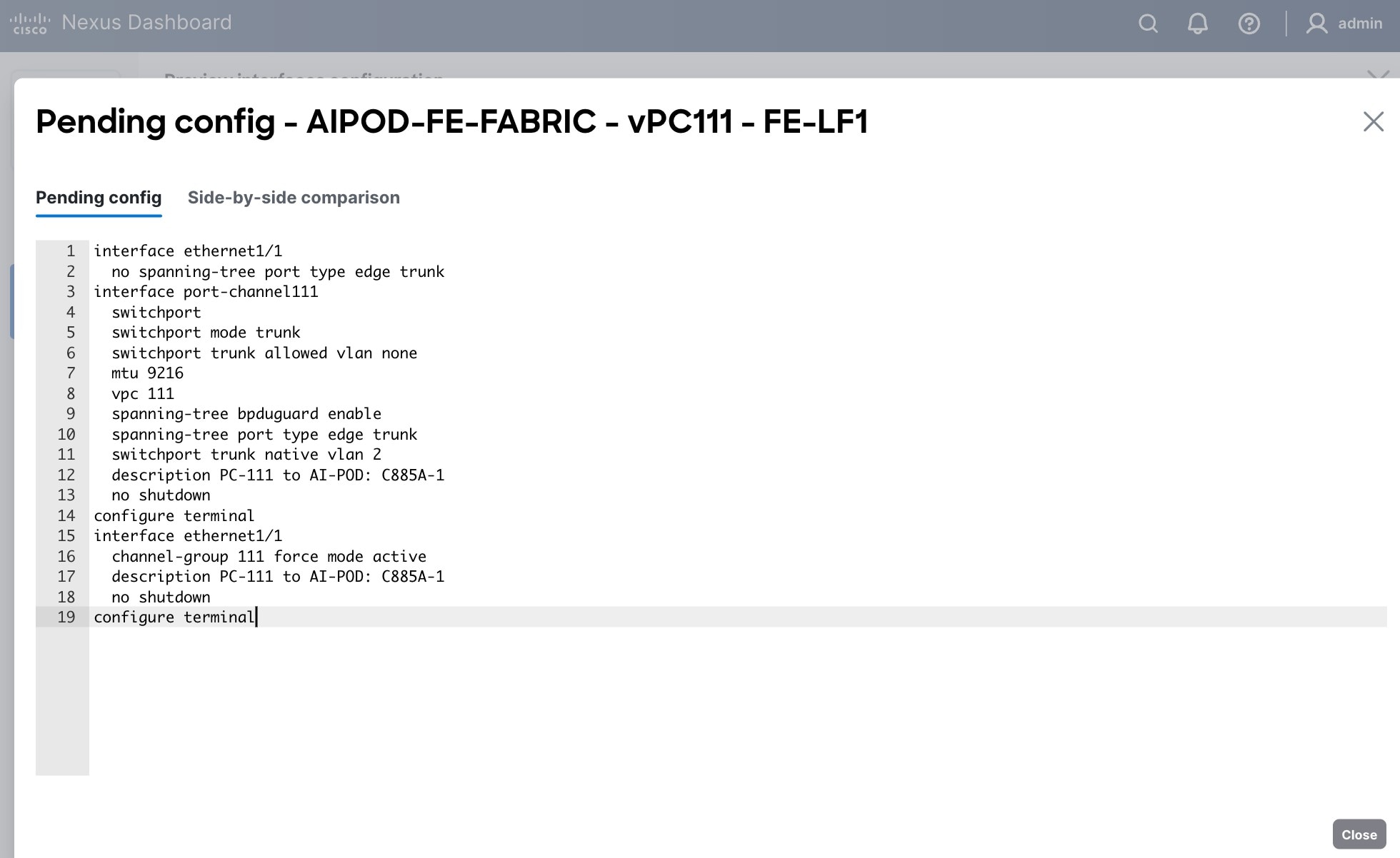
Step 9. Click the X in the top right corner and select Deploy and Deploy config to deploy the Pending config changes.
Step 10. Click Close when deployment completes successfully.
Step 11. Verify that all the interfaces and port-channel is up on each switch in the leaf switch pair that connects to the UCS node. It may take a few minutes for the vPC to go from Not discovered to consistent state.
Procedure 2. Deploy vPCs to remaining UCS C885A GPU nodes
Step 1. Repeat the previous procedure to provision layer 2 connectivity from the compute/management leaf switches to the remaining 3 UCS nodes in the cluster.
Step 2. Verify that all the interfaces and port-channel is up on each switch in the leaf switch pair that connects to the UCS nodes. It may take a few minutes for the vPC to go from Not discovered to consistent state.

(Ubuntu) Enable Layer 2 Connectivity to NVIDIA BCM Nodes
If running Ubuntu on the Cisco UCS C885A M8 nodes under NVIDIA BCM, to enable Layer 2 connectivity to the BCM (UCS) node(s) from the FE fabric, you will be configuring two vPCs from the same BCM node: one to compute/management leaf pair and another storage leaf pair.
Table 10. Setup Parameters for FE Fabric: Layer 2 Connectivity to NVIDIA BCME Nodes
| Parameter Type |
Parameter Name | Value |
Parameter Type |
| Virtual Port Channel (vPC) |
To BCME Node |
Management/Control/Workload Management Node |
| vPC/PC1 - ID |
17 |
|
| vPC Pair |
FE-LF1, FE-LF2 |
|
| Ports |
1/21 |
|
| vPC/PC1 - ID |
18 |
|
| vPC Pair |
FE-SLF1, FE-SLF2 |
|
| Ports |
1/24 |
|
To enable Layer 2 connectivity to the BCM (UCS) node(s) from the FE fabric, follow the procedures below.
Procedure 1. Deploy first vPC to BCM node from compute leaf switch pair
Step 1. Use a web browser to navigate to Nexus Dashboard. Use the management IP of any node in the ND cluster. Log in using admin account.
Step 2. From the left navigation menu, go to Manage > Fabrics.
Step 3. Select the FE fabric and navigate to Connectivity > Interfaces tab.
Step 4. Click the lower of the two Actions buttons and select Create interface.

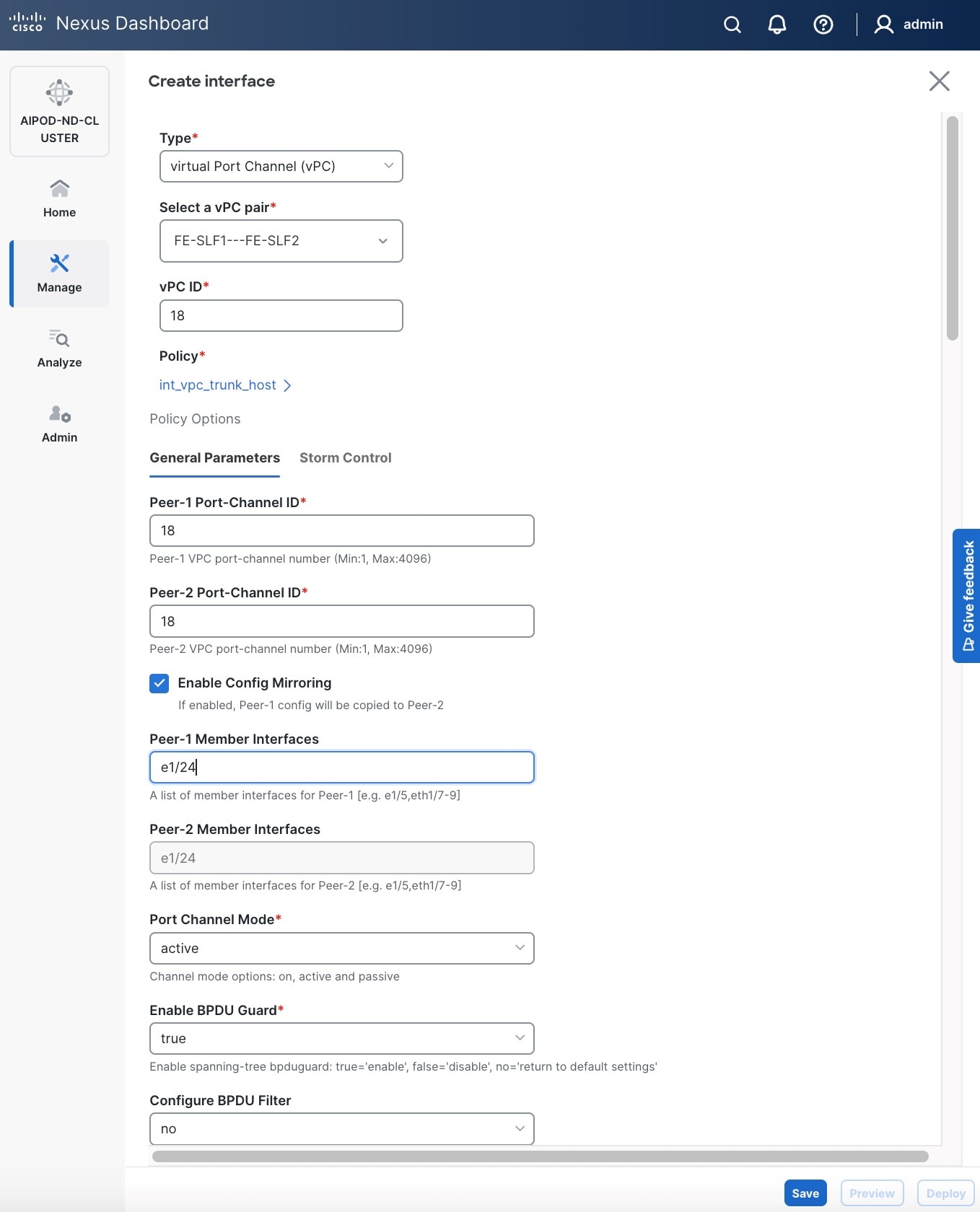
Step 5. In the Create interface window:
● Specify the TypeType of interface as virtual Port Channel (vPC)virtual Port Channel (vPC) from the drop-down list.
● For the Select a vPC pairSelect a vPC pair, select the leaf switch pair from the drop-down list.
● Specify a vPC IDvPC ID for the firstfirst vPC to the BCME nodeBCME node. Port Channel IDs from each switch to the first UCS node should match the vPC ID (see screenshot below).
● Leave the Policy as int_vpc_trunk_host.
● EnableEnable checkbox for Config MirroringConfig Mirroring to configure both vPC peer switches identically.
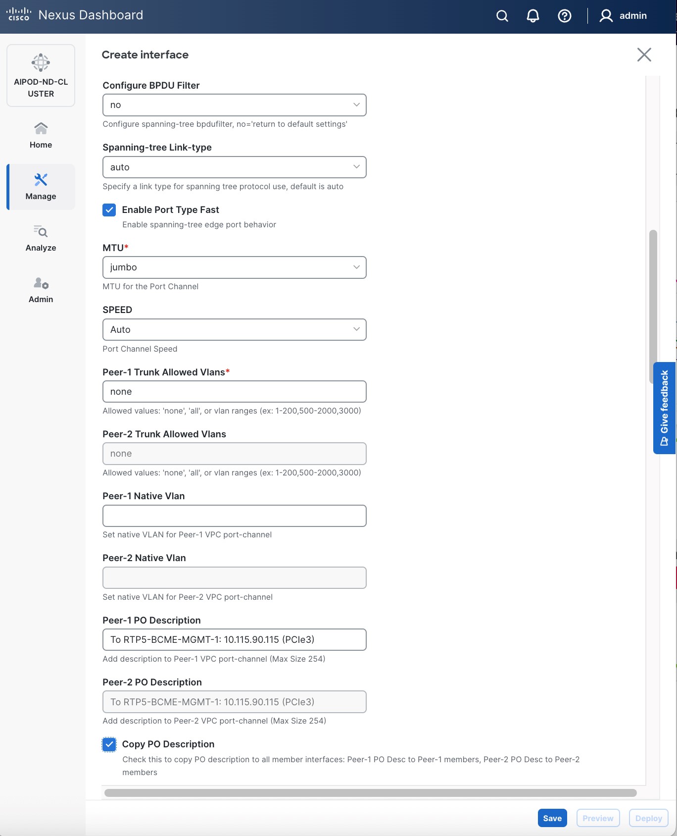
● Specify Peer-1 Member Interfaces Peer-1 Member Interfaces that connects to the BCME node.
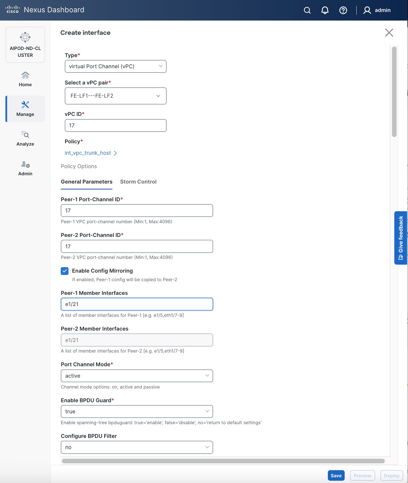
● Scroll down and fill remaining fields: Native VLAN (optional), Peer-1 PO Description, Copy PO Description.
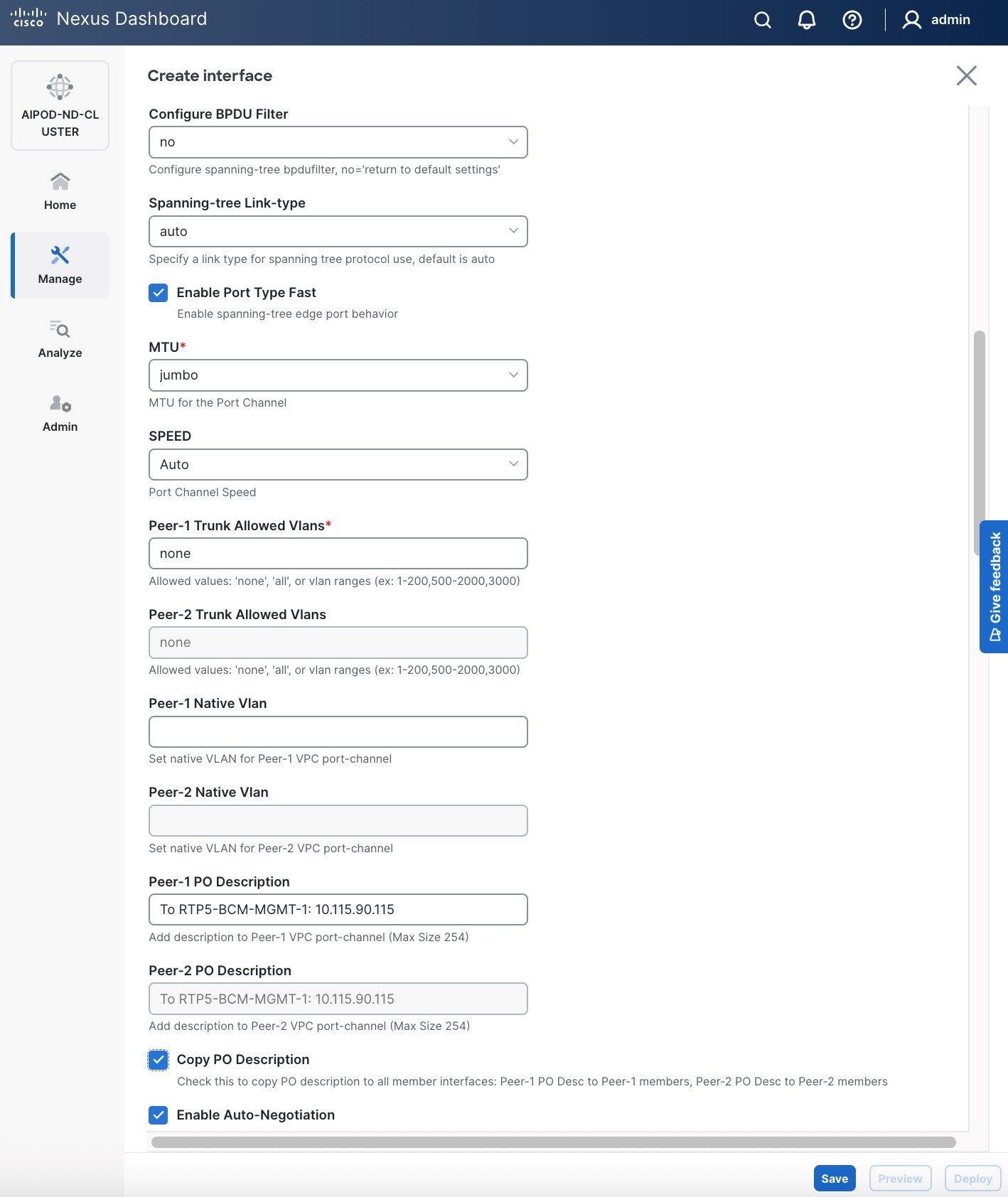
Step 6. Click Save.
Step 7. Click Preview.
Step 8. Click Close, then click Cancel.
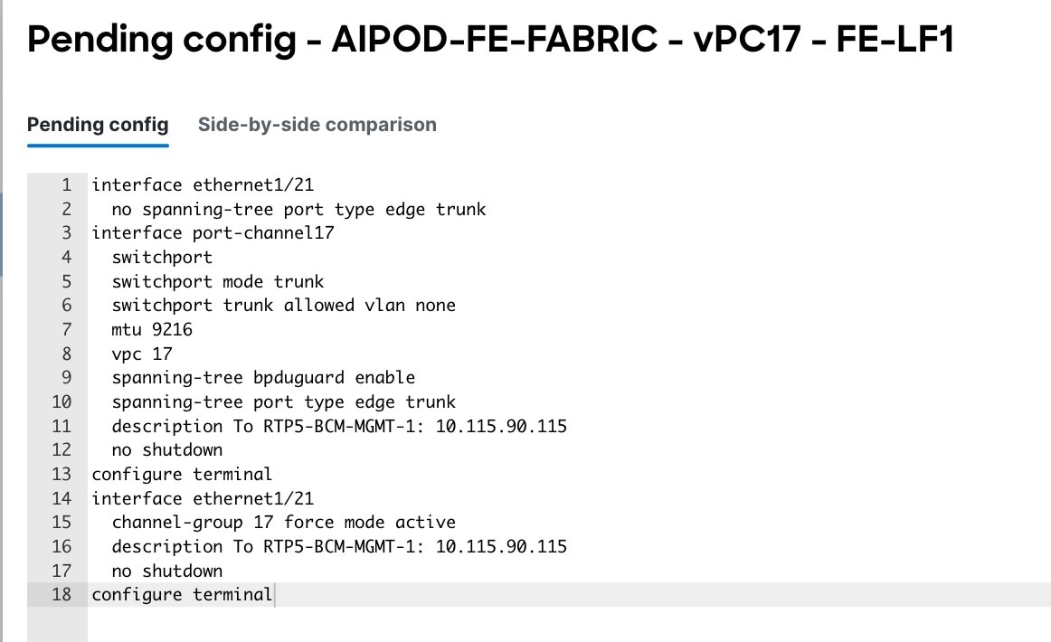
Step 9. Click Deploy. The Pending Config is the configuration shown in a previous step.
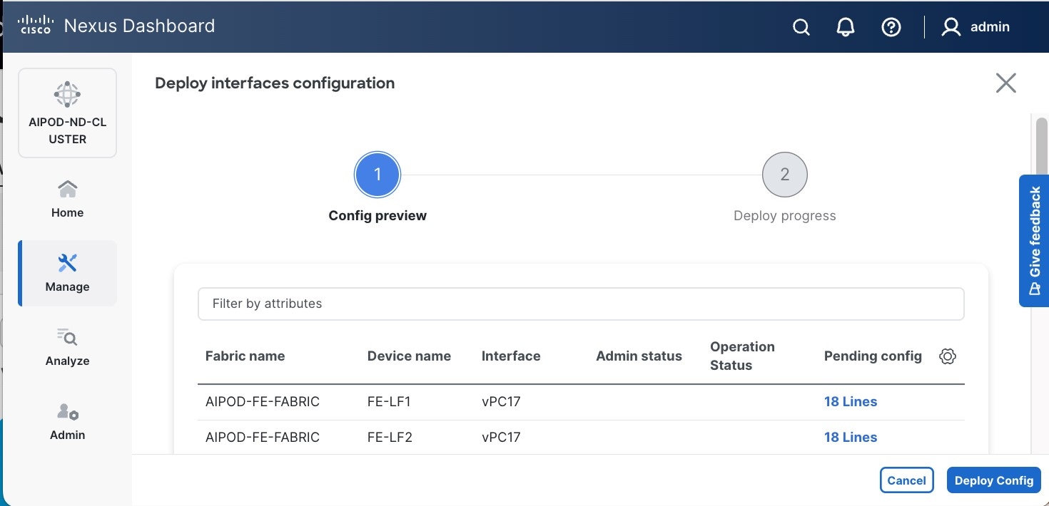
Step 10. Click Deploy Config.
Step 11. Verify that all the interfaces and port-channels are up on each switch in the vPC leaf pair that connects to the BCME node. It may take a few minutes for the vPC to go from Not discovered to consistent state.
Procedure 2. Deploy second vPC to BCM node from storage leaf switch pair
Step 1. Repeat the previous procedure for the second vPC from storage leaf pair to BCME node.
Step 2. Click Save.
Step 3. Click Deploy, then click Deploy Config.
Step 4. Verify that all the interfaces and port-channels are up on each switch in the vPC leaf pair that connects to the BCM node. It may take a few minutes for the vPC to go from Not discovered to consistent state.
(Ubuntu) Enable Layer 2 Connectivity to UCS GPU Nodes from FE Fabric
If running Ubuntu on the Cisco UCS C885A M8 nodes under NVIDIA BCM, to enable Layer 2 connectivity to UCS C885A GPU nodes from the FE fabric, you will be configuring four vPCs, one per UCS C885A node. Each vPC will use one port on each switch in the compute leaf pair to connect to the UCS node.
If running OpenShift on the Cisco UCS C885A M8 nodes, follow this procedure but set the native VLAN to 2 below instead of 703.
Table 11. Setup Parameters for FE Fabric: Layer 2 Connectivity to UCS GPU Nodes
| Parameter Type |
Parameter Name | Value |
Parameter Type |
| Leaf Switches |
FE-LF1, FE-LF2 |
|
| UCS Nodes |
4 x UCS C885A GPU Nodes |
Each node is dual-homed to FE-LF1 & FE-LF2 |
| Virtual Port Channel (vPC) |
To UCS C885As |
UCS GPU Nodes |
| vPC/PC1 - ID |
111 |
To UCS C885A-1 |
| vPC Pair |
FE-LF1, FE-LF2 |
|
| Ports |
1/1 |
On each Leaf switch |
| vPC/PC2 – ID |
112 |
To UCS C885A-2 |
| vPC Pair |
FE-LF1, FE-LF2 |
|
| Ports |
1/2 |
On each Leaf switch |
| vPC/PC3 - ID |
113 |
To UCS C885A-3 |
| vPC Pair |
FE-LF1, FE-LF2 |
|
| Ports |
1/3 |
On each Leaf switch |
| vPC/PC4 – ID |
114 |
To UCS C885A-4 |
| vPC Pair |
FE-LF1, FE-LF2 |
|
| Ports |
1/4 |
On each Leaf switch |
To enable Layer 2 connectivity to UCS C885A GPU nodes from the FE fabric, follow the procedures below. You will be configuring four vPCs, one per UCS C885A node. Each vPC will use one port on each switch in the compute leaf pair to connect to the UCS node.
Procedure 1. Deploy first vPC to first UCS C885A GPU node
Step 1. Use a web browser to navigate to Nexus Dashboard. Use the management IP of any node in the ND cluster. Log in using admin account.
Step 2. From the left navigation menu, go to Manage > Fabrics.
Step 3. Select the FE fabric and navigate to Connectivity > Interfaces tab.
Step 4. Click the lower of the two Actions buttons and select Create interface.

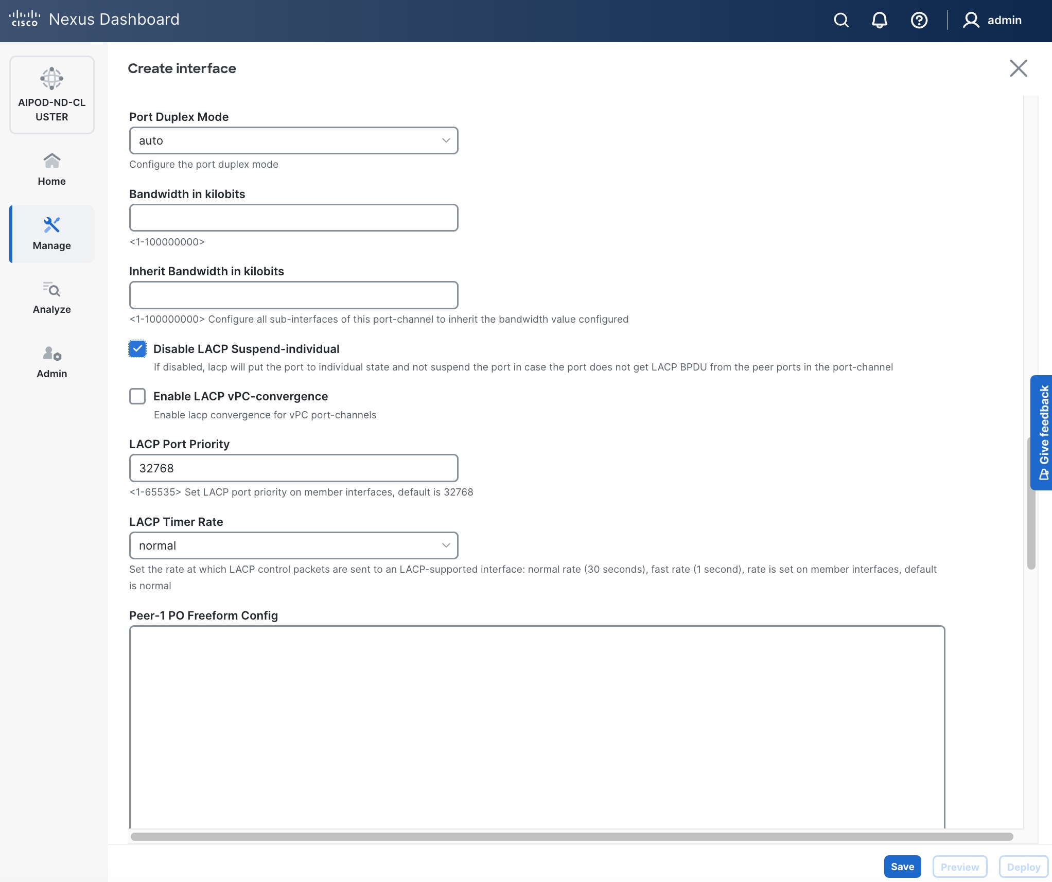
Step 5. In the Create interface window:
● Specify the TypeType of interface as virtual Port Channel (vPC)virtual Port Channel (vPC) from the drop-down list.
● For the Select a vPC pairSelect a vPC pair, select the compute leaf switch VPC pair from the dropdown list.
● Specify a vPC IDvPC ID for the vPC to the first first UCS GPU node. Peer-1 and Peer-2 Port-Channel ID should match that of the vPC ID.
● Leave the Policy as int_vpc_trunk_host.
● Enable checkbox for Config Mirroring.
● Specify Peer-1 Member InterfacesPeer-1 Member Interfaces that connects to first UCS node.
● Specify Peer-1 Native Vlan. Peer-1 Native Vlan. – If running OpenShift on the C885A nodes, set the Peer-1 Native VLAN to 2
● Specify Peer-1 PO Description.
● EnableEnable checkbox for Copy PO DescriptionCopy PO Description to copy PO description to all member interfaces.
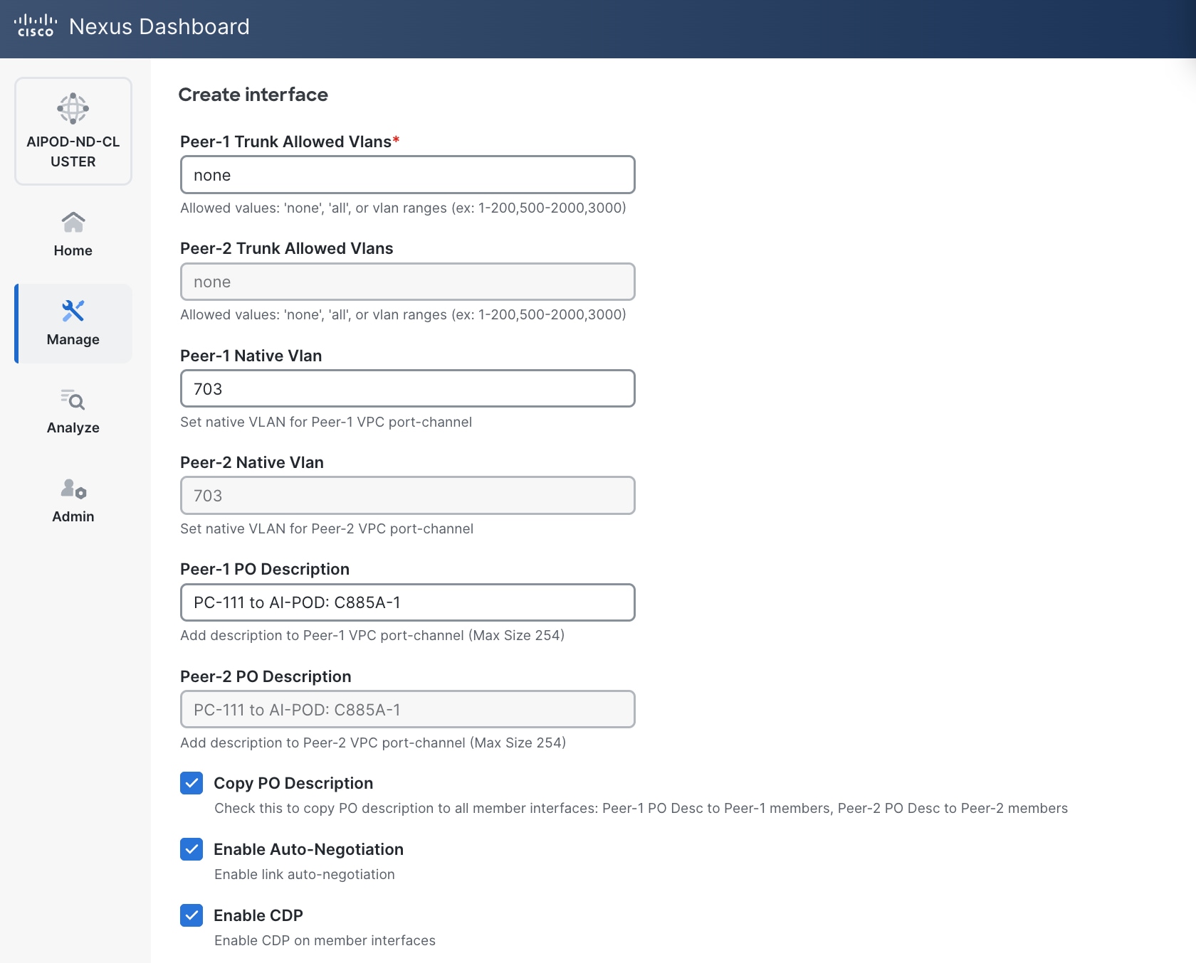
● Enable checkbox for Disable LACP Suspend-individual Disable LACP Suspend-individual – If running OpenShift on the C885A nodes, do not select this checkbox.
● Leave everything else as is. Additional configuration changes can be made later as needed.
Step 6. Click Save.
Step 7. Click Preview.
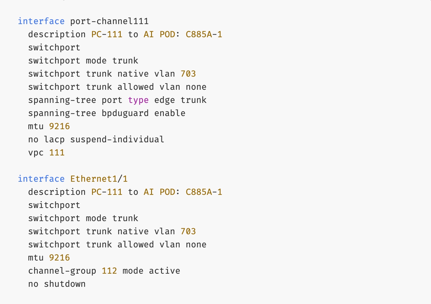
Step 8. To view the Pending config changes, click the Pending Config column for each switch (X lines) to see the configuration. The configuration is provided as a reference from one leaf switch.
Step 9. Click the X in the top right corner and select Deploy and Deploy config to deploy the Pending config changes.
Step 10. Click Close when deployment completes successfully.
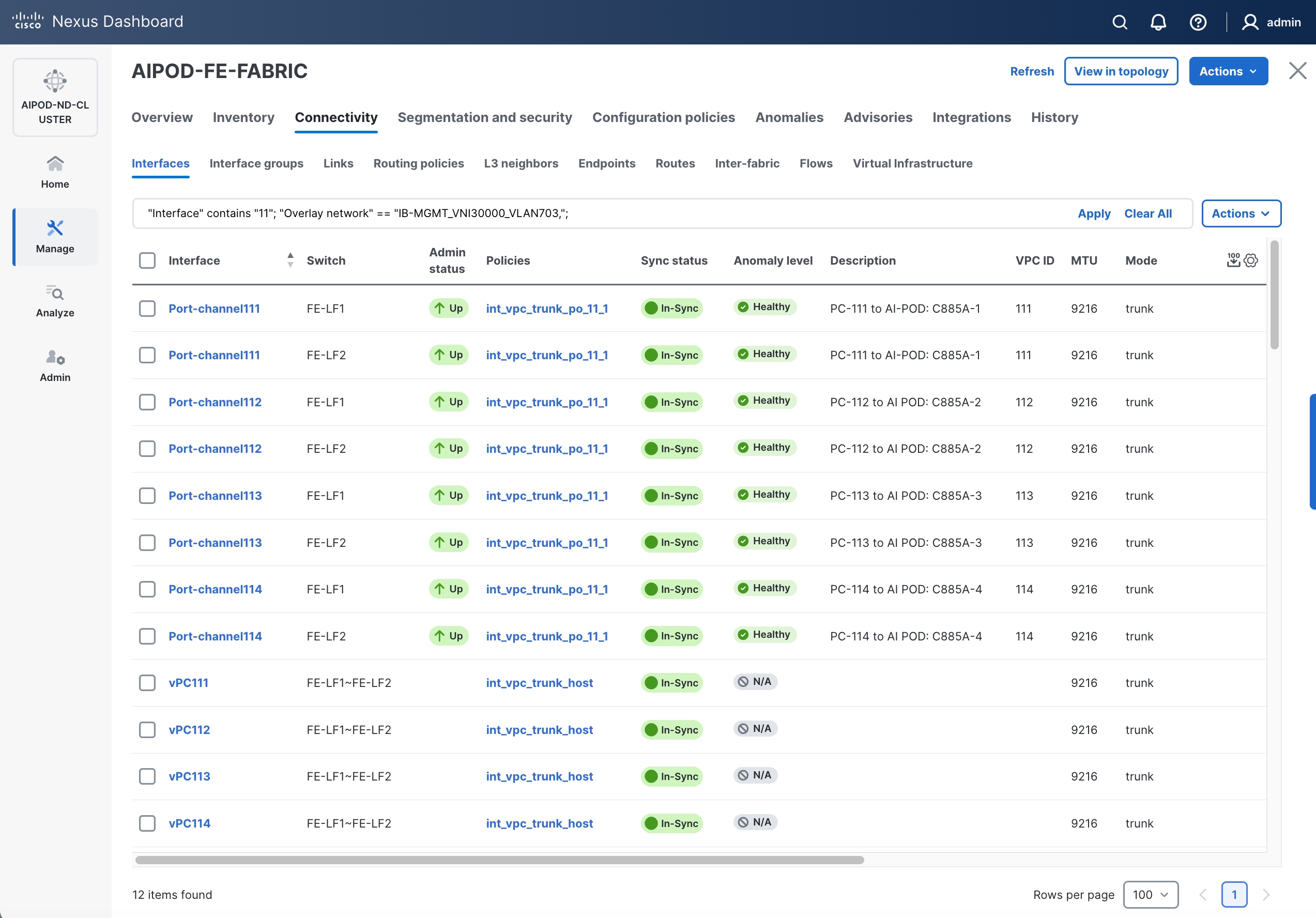
Step 11. Verify that all the interfaces and port-channel is up on each switch in the leaf switch pair that connects to the UCS node. It may take a few minutes for the vPC to go from Not discovered to consistent state.
The deployed configuration on one leaf switch is provided as a reference below:
Procedure 2. Deploy vPCs to remaining UCS C885A GPU nodes
Step 1. Repeat the previous procedure to provision layer 2 connectivity from the compute/management leaf switches to the remaining 3 UCS nodes in the cluster.
Step 2. Verify that all the interfaces and port-channel is up on each switch in the leaf switch pair that connects to the UCS nodes. It may take a few minutes for the vPC to go from Not discovered to consistent state.
Enable In-Band Management Connectivity to UCS GPU and Management Nodes
The In-band management (IB-MGMT) network in the FE fabric will provide the following connectivity:
● Connectivity from control, management and services nodes to the UCS GPU nodes where the AI workload is running
● Connectivity to other networks (networks outside this FE fabric to other networks within the enterprise or external to the enterprise)
In a Red Hat OpenShift environment, this network will also serve as the Cluster IP pod network for the OpenShift cluster running on UCS management (Kubernetes Control) nodes and UCS GPU (Kubernetes Worker) nodes.
Table 12. Setup Parameters for FE Fabric: In-Band Management Connectivity to UCS Management and GPU Nodes
| Parameter Type |
Parameter Name | Value |
Parameter Type |
| IB-MGMT Network |
|
|
| Name |
IB-MGMT_VN30000_VLAN703 |
|
| Layer 2 Only |
No |
|
| IB-MGMT VRF |
|
|
| VRF Name |
FE-MGMT_VN50000 |
|
| VRF ID |
50000 |
(System Proposed) |
| VLAN ID |
2000 |
(System Proposed) |
| VRF Interface Description |
FE-MGMT VRF |
|
| VRF Description |
Frontend Fabric – Management VRF |
|
| IB-MGMT Network Contd. |
|
|
| Network ID |
30000 |
|
| VLAN ID |
703 |
|
| IPv4 Gateway/Netmask |
10.115.90.126/26 |
|
| VLAN Name |
IB-MGMT_VLAN |
|
| Interface Description |
IB-MGMT |
|
| UCS C885A GPU Nodes |
|
|
| vPC Leaf Switch Pair |
FE-LF1, FE-LF2 |
vPC Leaf Switch Pair |
| UCS C885-A Node-1 Interface |
Port-Channel 111 |
|
| UCS C885-A Node-2 Interface |
Port-Channel 112 |
|
| UCS C885-A Node-3 Interface |
Port-Channel 113 |
|
| UCS C885-A Node-4 Interface |
Port-Channel 114 |
|
| Management UCS X-Direct Chassis |
|
|
| vPC Leaf Switch Pair |
FE-LF1, FE-LF2 |
|
| UCS X-Direct (-A Uplinks) |
Port-Channel 15 |
|
| UCS X-Direct (-B Uplinks) |
Port-Channel 16 |
|
To deploy the in-band management network and enable connectivity to the UCS GPU nodes, follow the procedures below.
Procedure 1. Deploy In-Band Management Connectivity for UCS GPU Nodes
Step 1. Use a web browser to navigate to Nexus Dashboard. Use the management IP of any node in the ND cluster. Log in using admin account.
Step 2. From the left navigation menu, go to Manage > Fabrics.
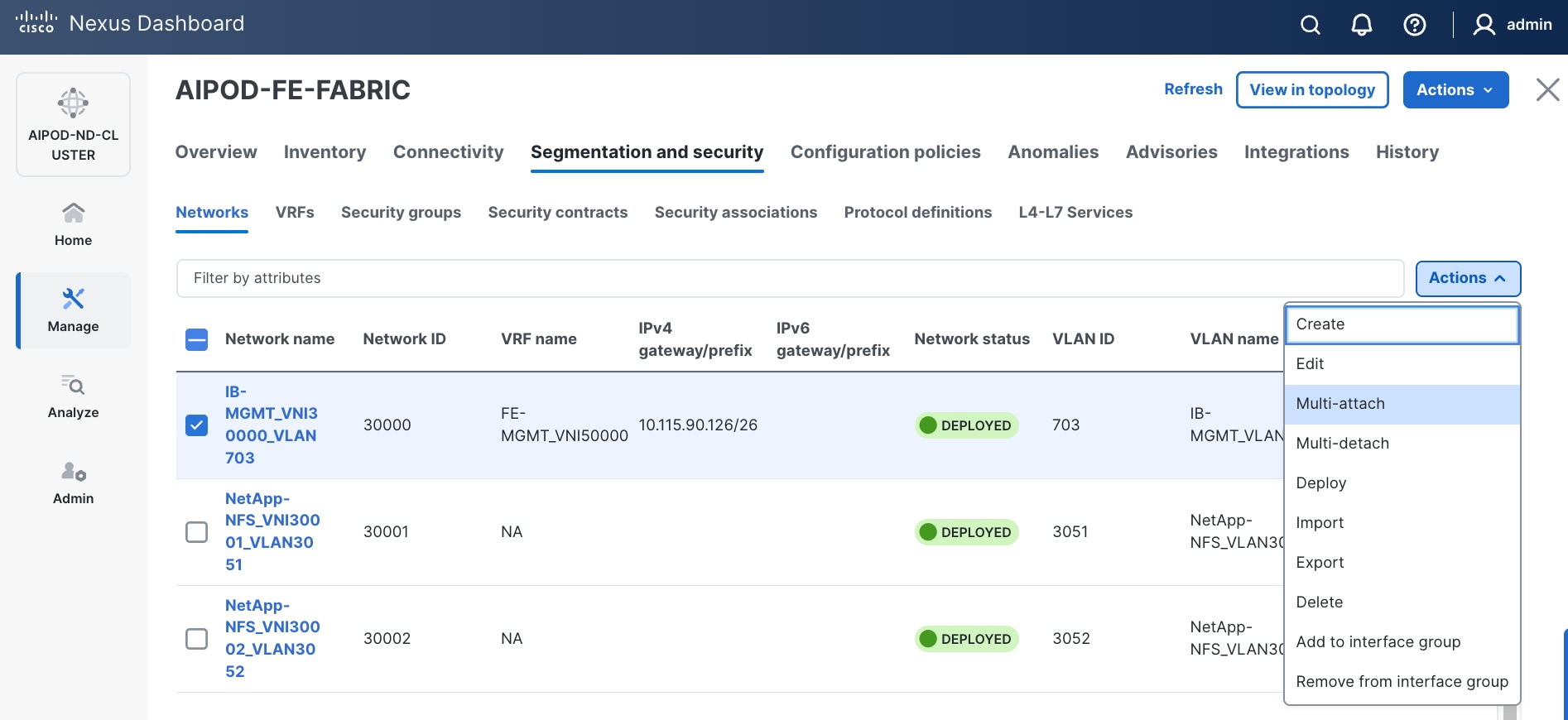
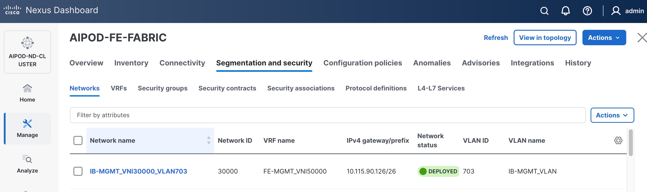
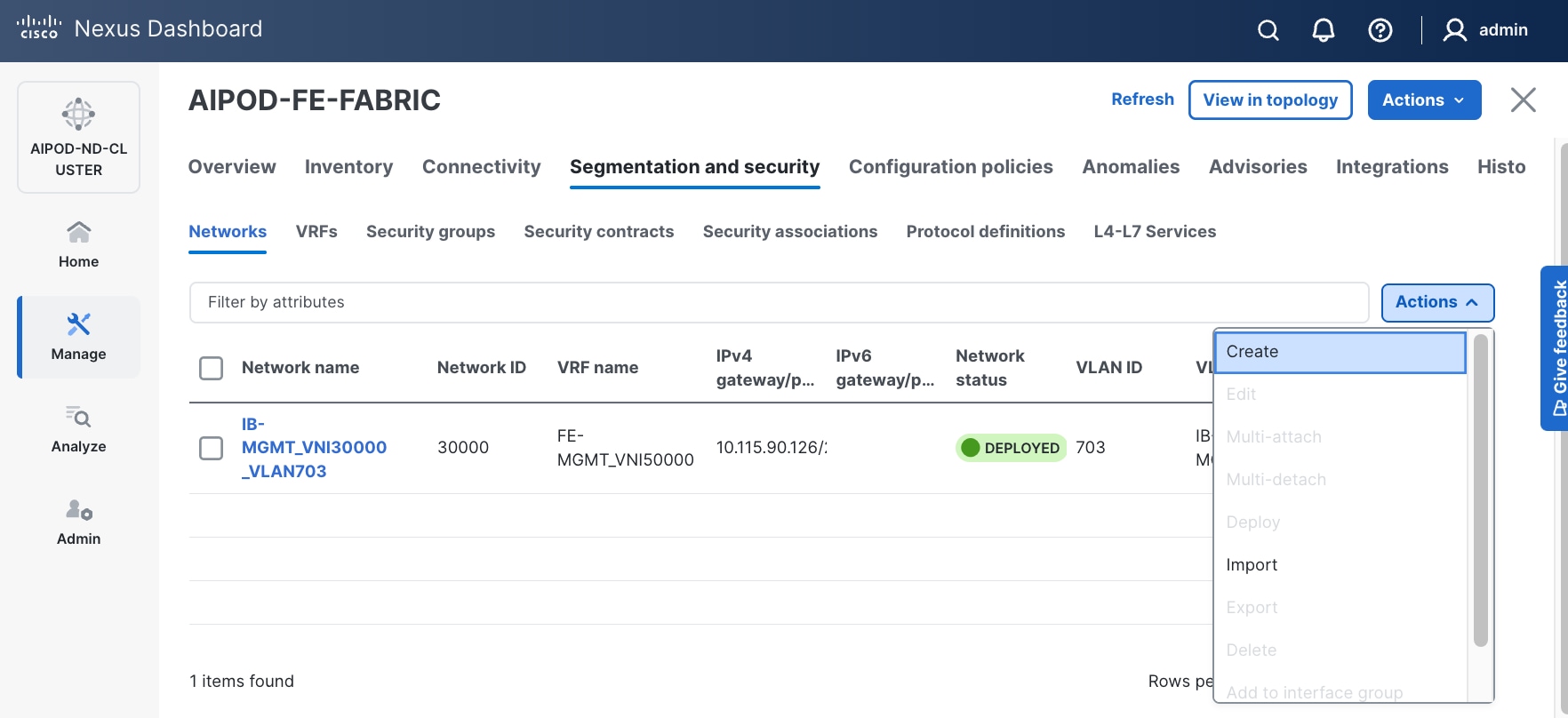
Step 3. Select the FE fabric and navigate to Segmentation and Security > Networks tab.
Step 4. Click the lower of the two Actions buttons and select Create from the list.
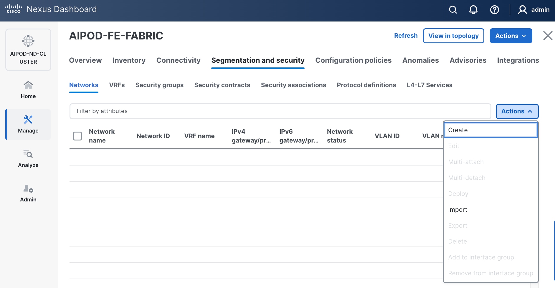
Step 5. In the Create Network window, specify the following:
● Network nameNetwork name for the IB-MGMT network.
● Leave unchecked the Layer 2 only Layer 2 only checkbox as IB-MGMT is a layer 3 overlay network.
● VRF nameVRF name. If a VRF hasn't been created already, you have an option from this window to also create a VRF.
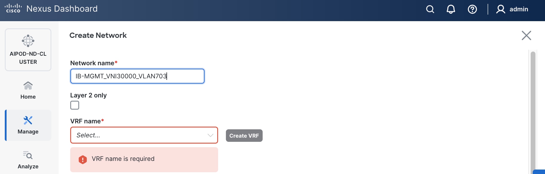
● To create a new VRF, click Create Create VRF. In the Create VRF Create VRF window, specify VRF ID (VRF ID (or use default), VLAN ID (VLAN ID (or click Propose VLAN Propose VLAN to let system define a VLAN), and optionally other parameters as shown in the screenshot.
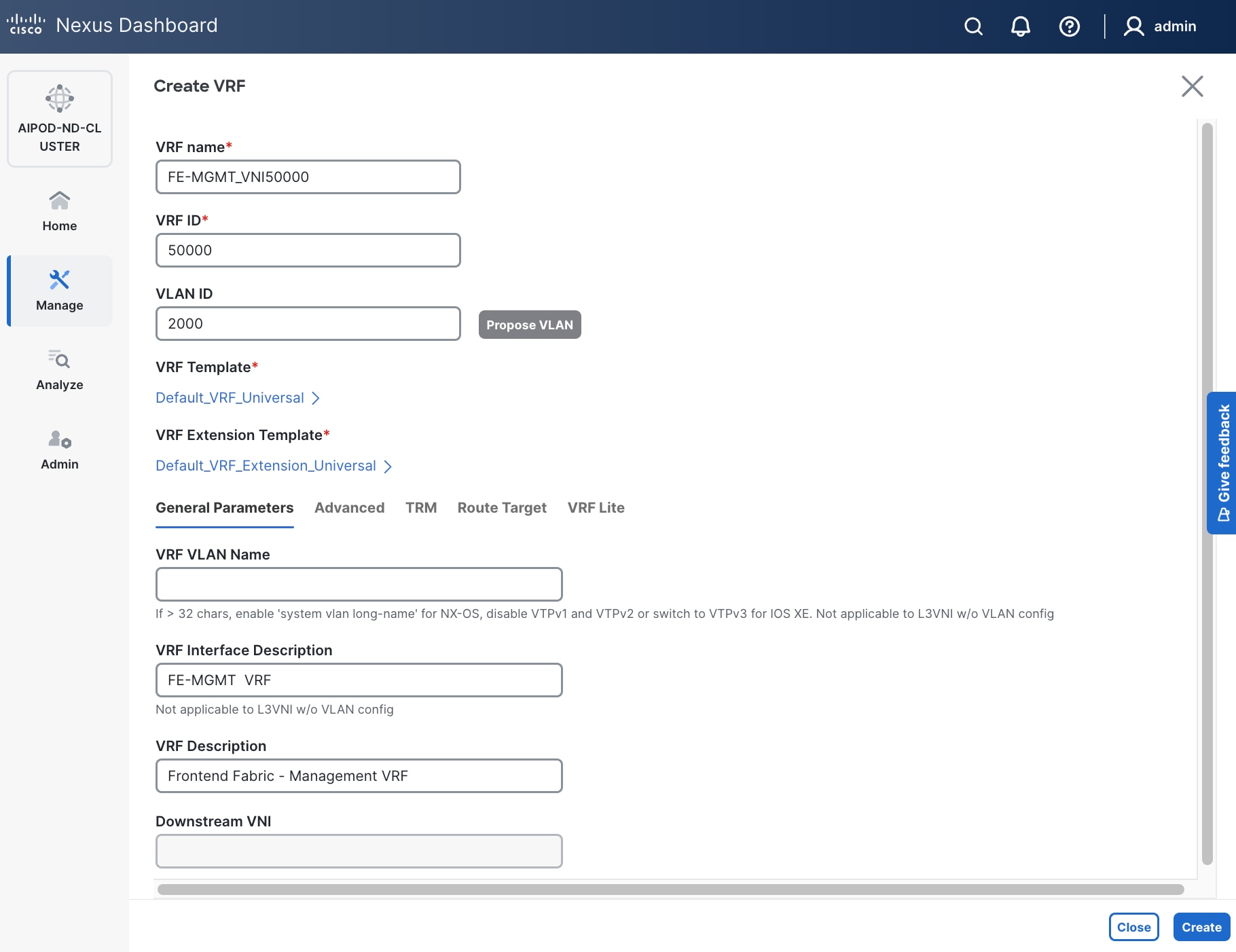
Step 6. Click Create to create the VRF and return to the Create Network window.
Step 7. In the Create Network window, specify the following:
● Network IDNetwork ID or use default.
● VLAN ID VLAN ID or click Propose VLAN Propose VLAN button to let system define a VLAN.
● In the General Parameters tab, specify IP Gateway/Netmask, VLAN Name and Interface Description.
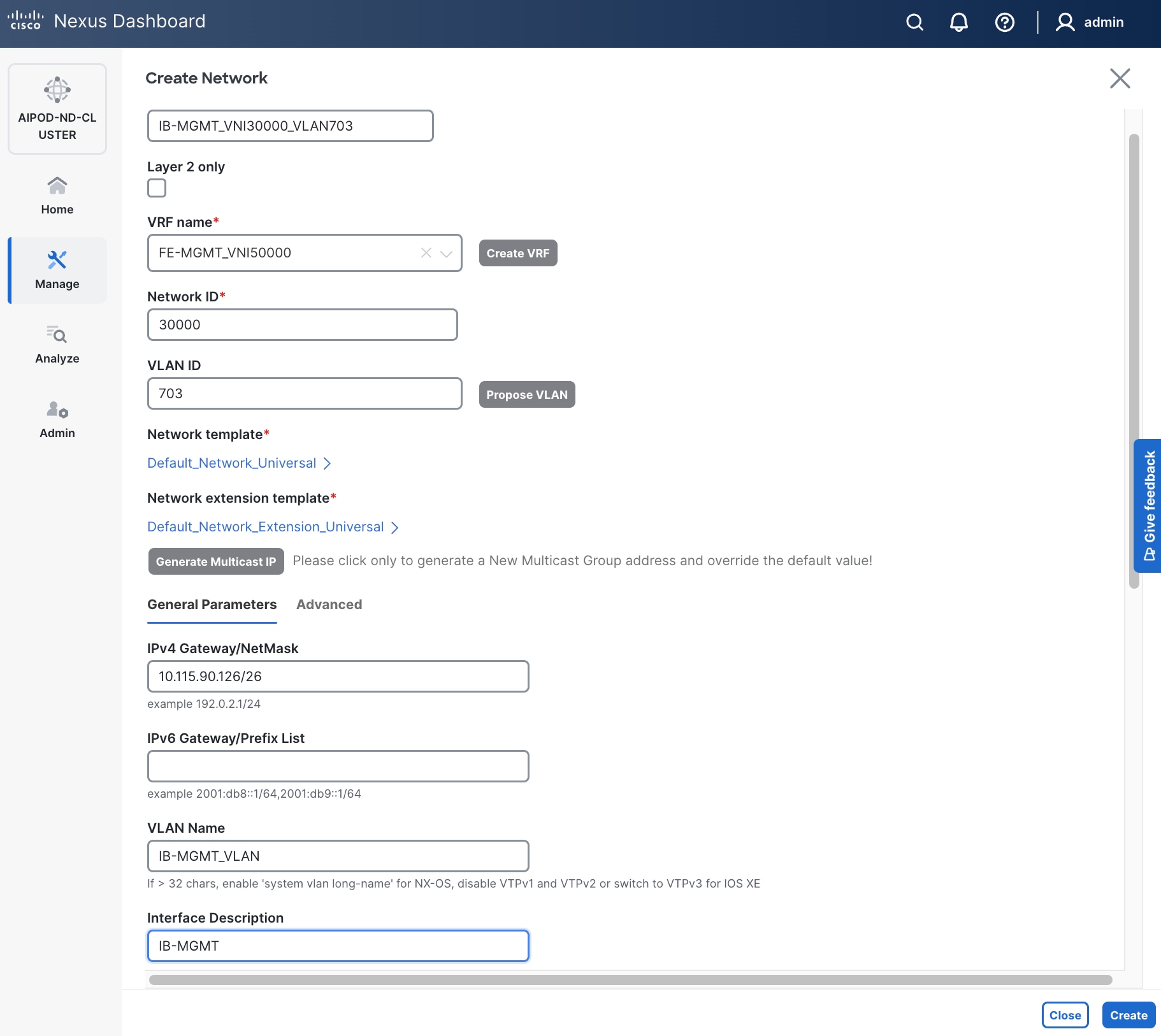
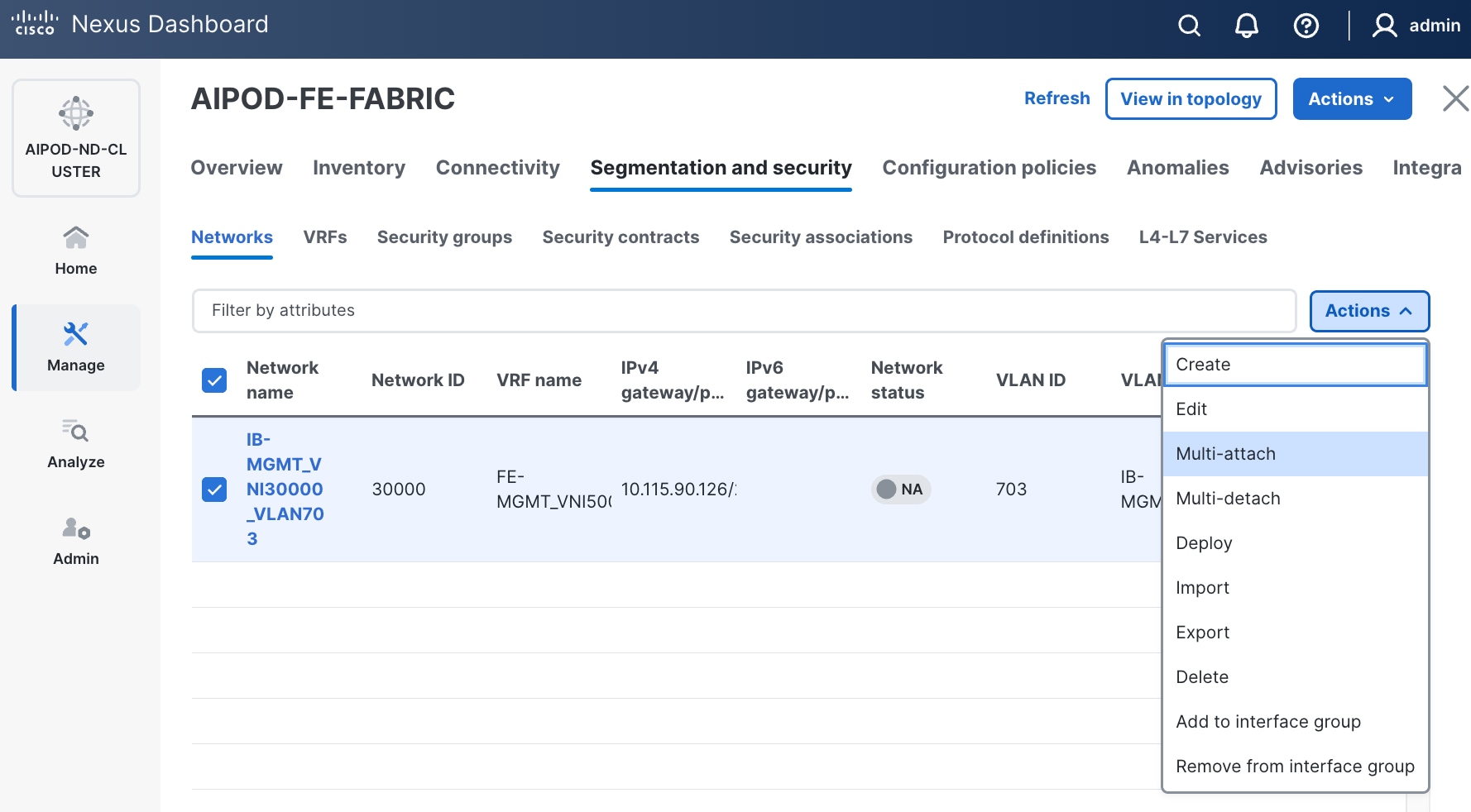
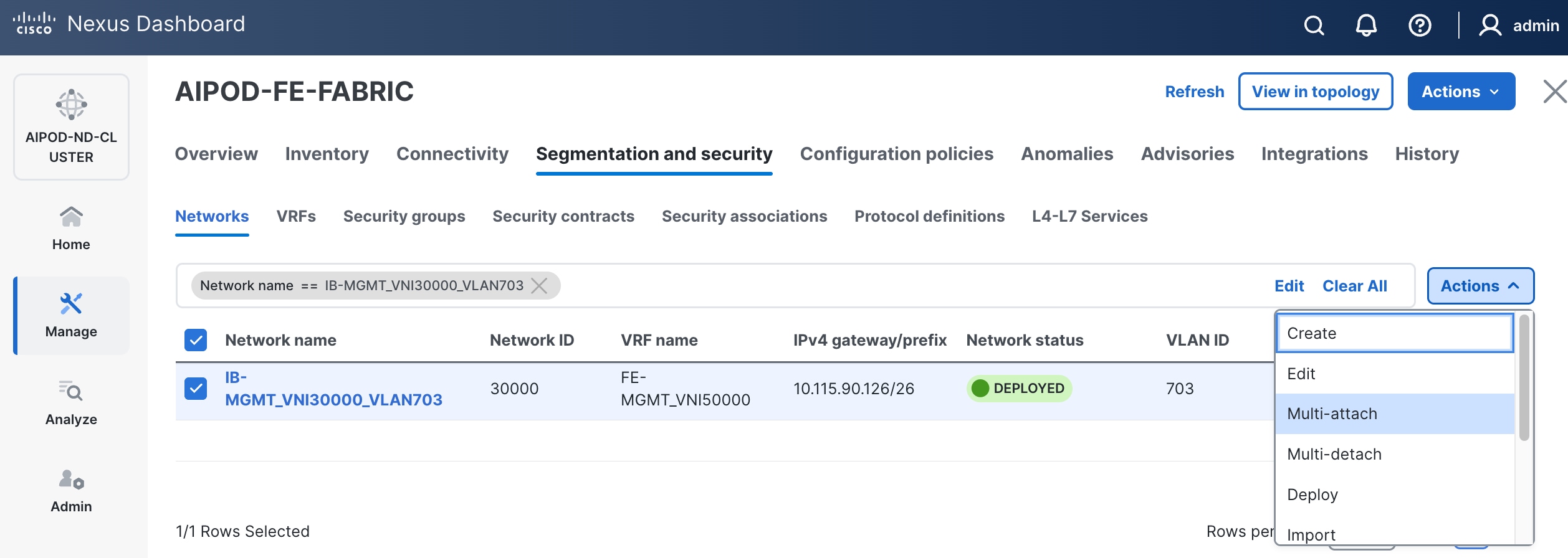
Step 8. Click Create to create the Network.
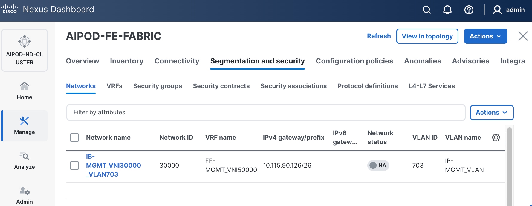
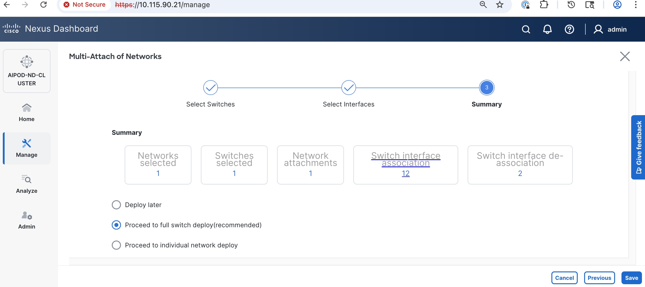
Step 9. Select newly created network and deploy it on both leaf pairs. Click the lower of the two Actions button and select Multi-attach from the list.
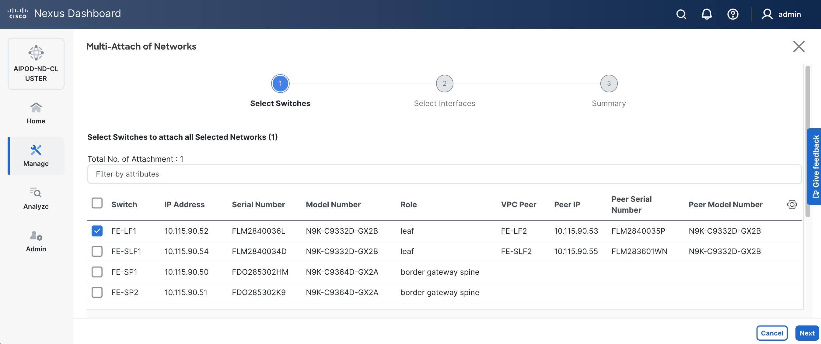
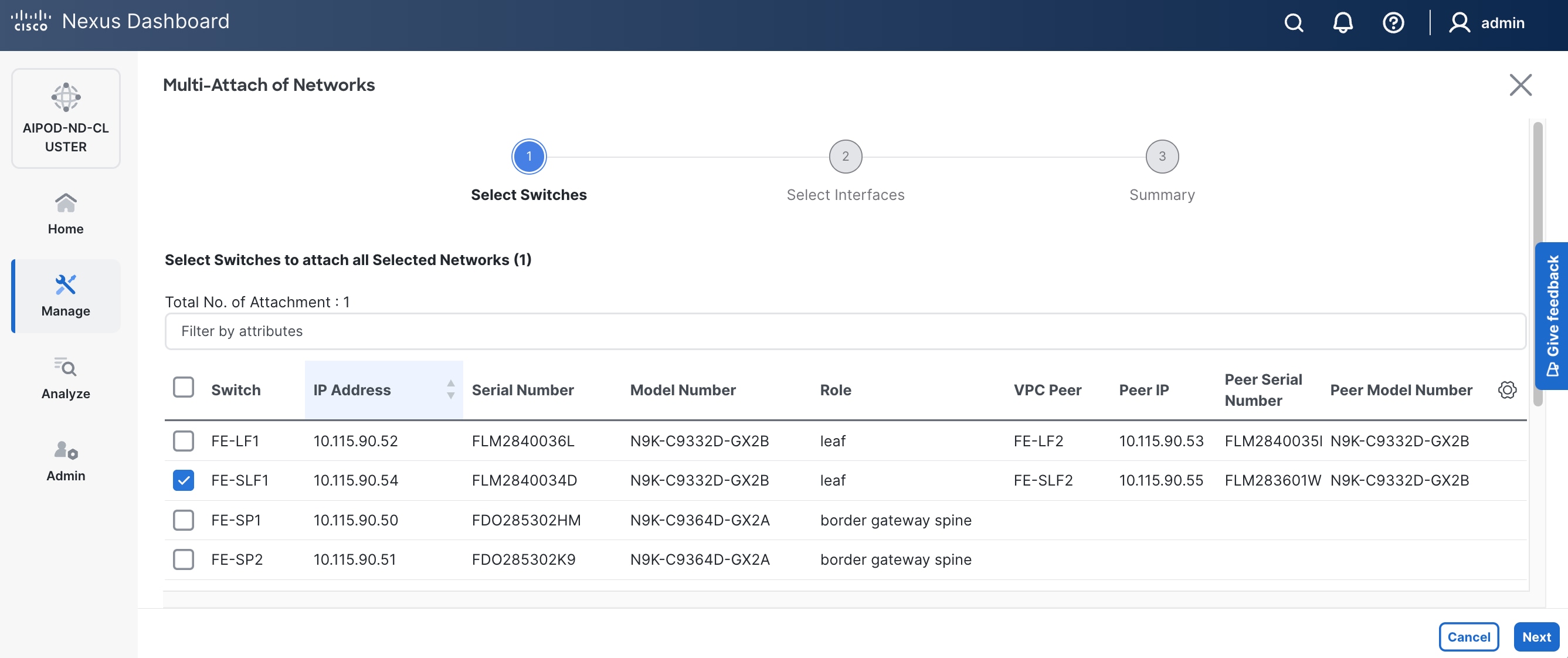
Step 10. Select the Leaf switch pairs. Enabling this network on storage leaf pairs, as shown below, may not be necessary in all deployments.
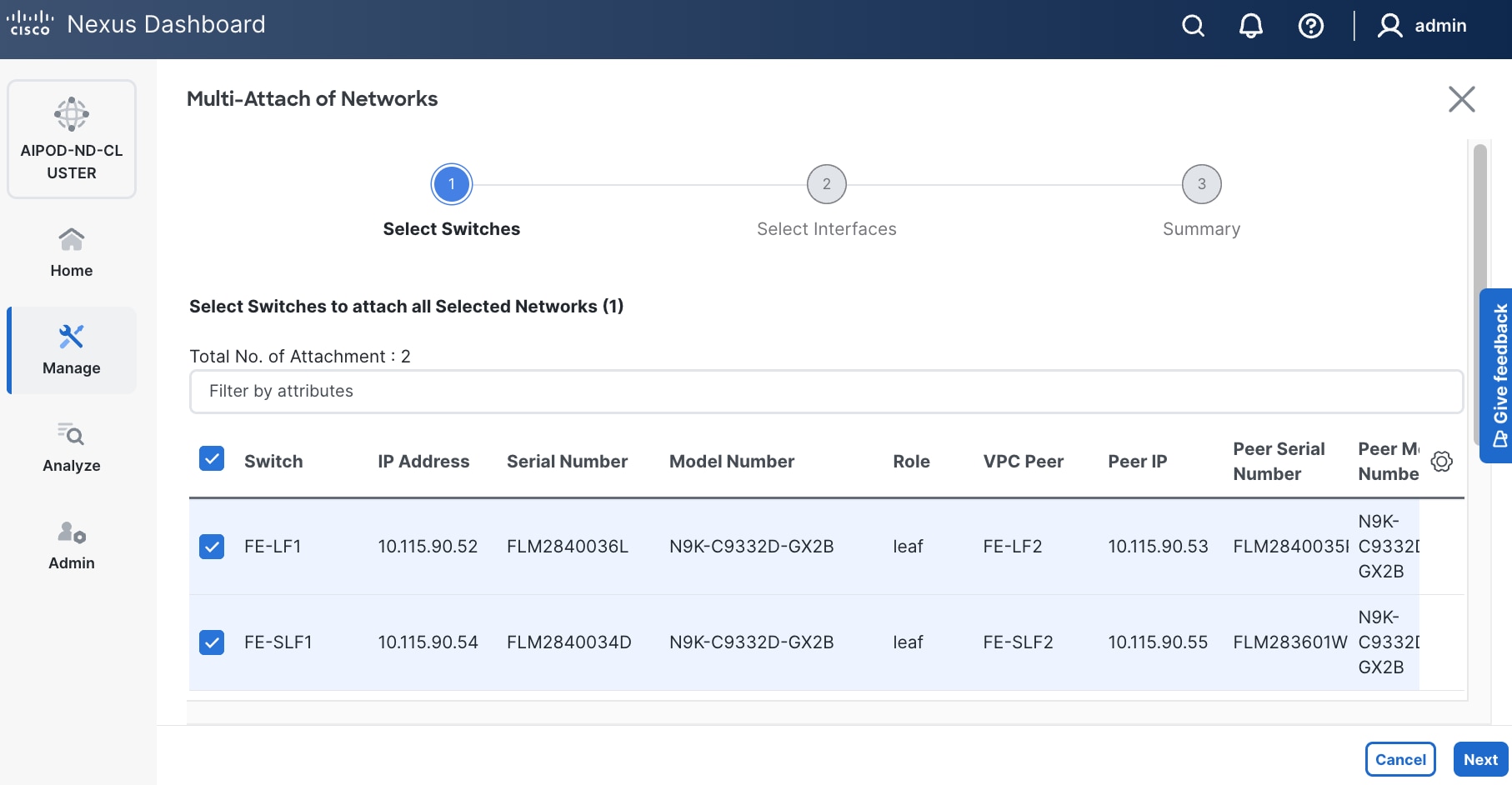
Step 11. Click Next.
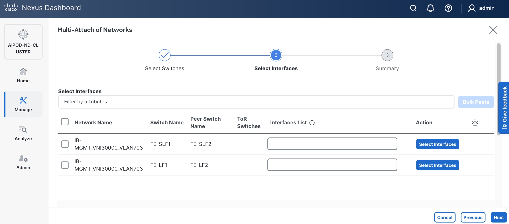
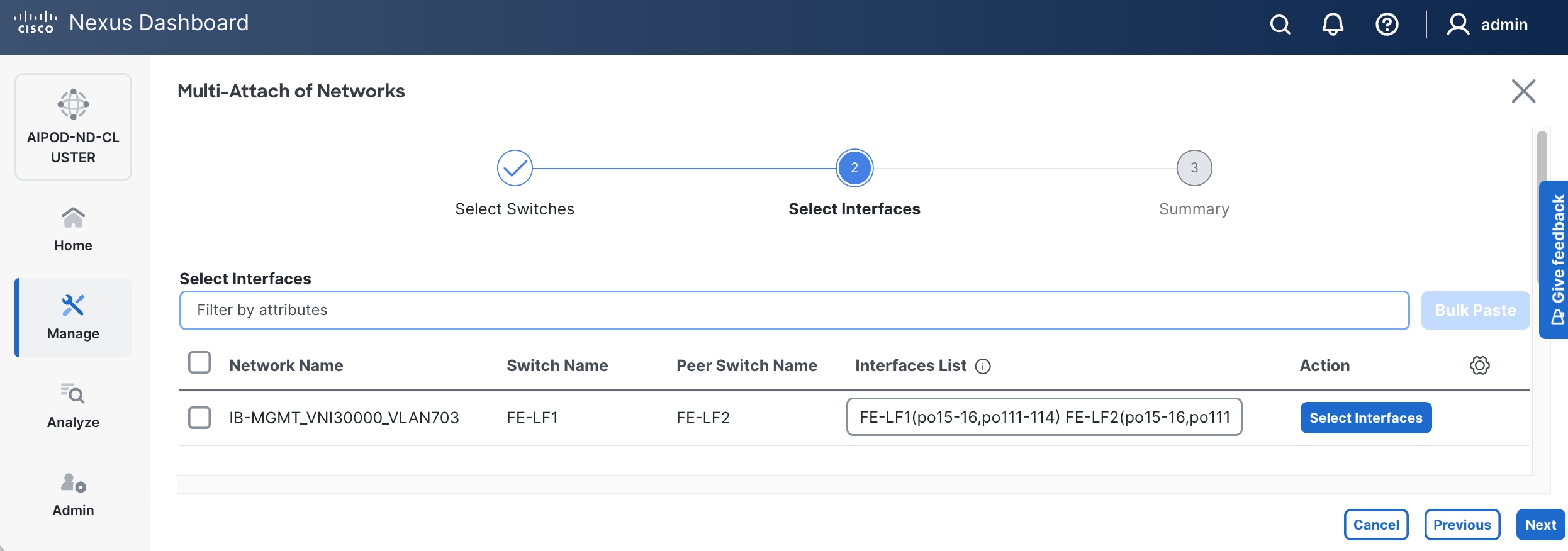
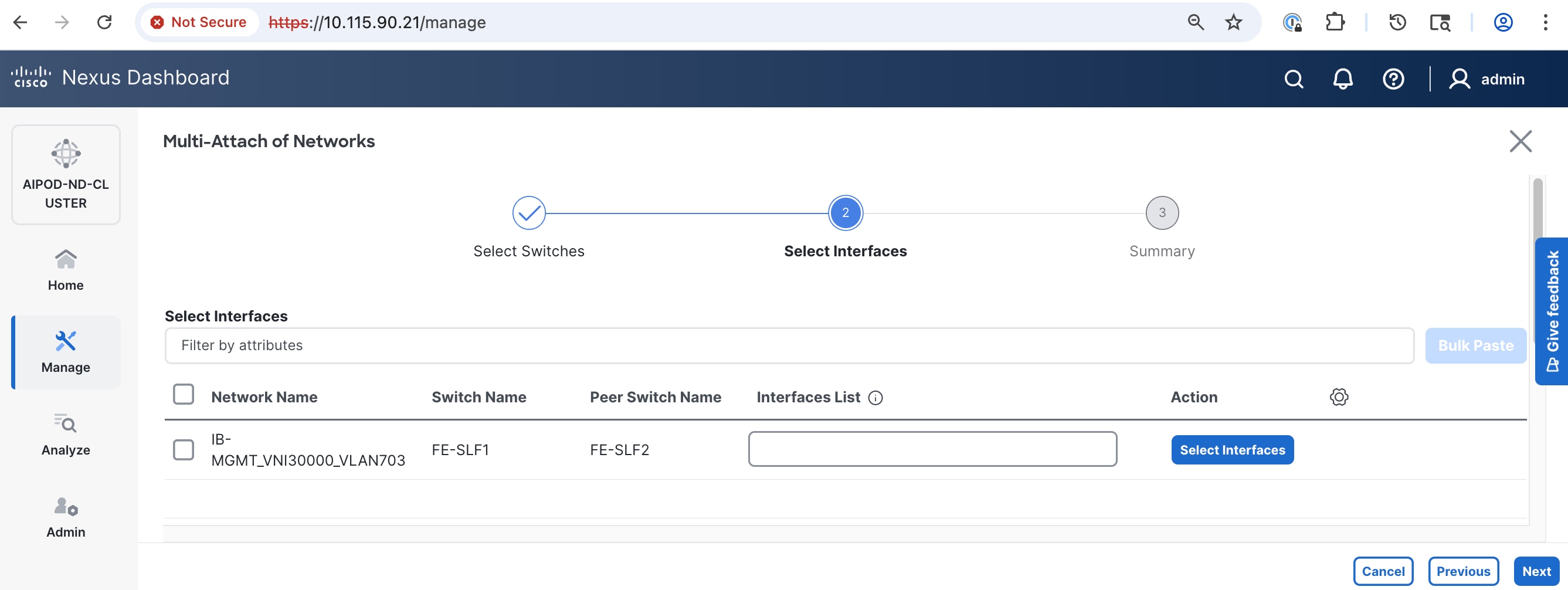
Step 12. Select each switch pair in the list and click Select interfaces on the right to deploy this network as a trunked VLAN (VLAN 703) on the selected interfaces. Select the interfaces on the compute leaf switches that connect to the UCS GPU nodes. Additional interfaces can be added later as needed.
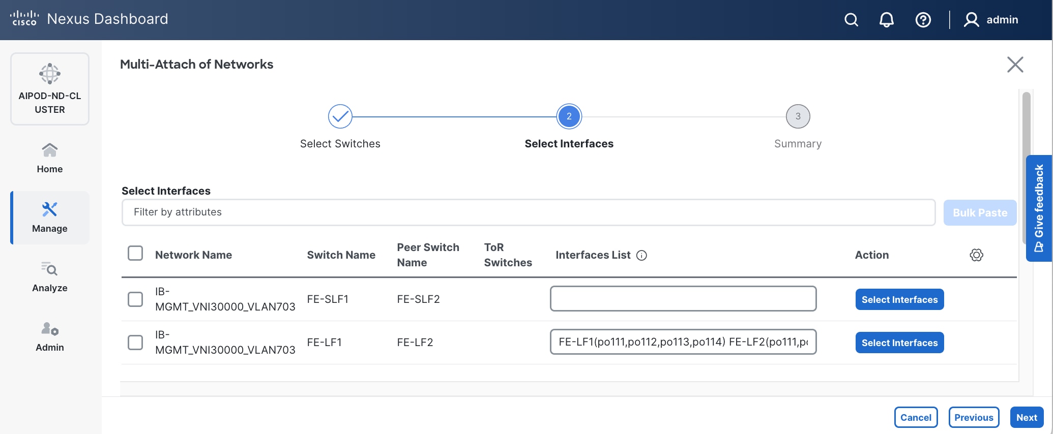
Step 13. Click Next.
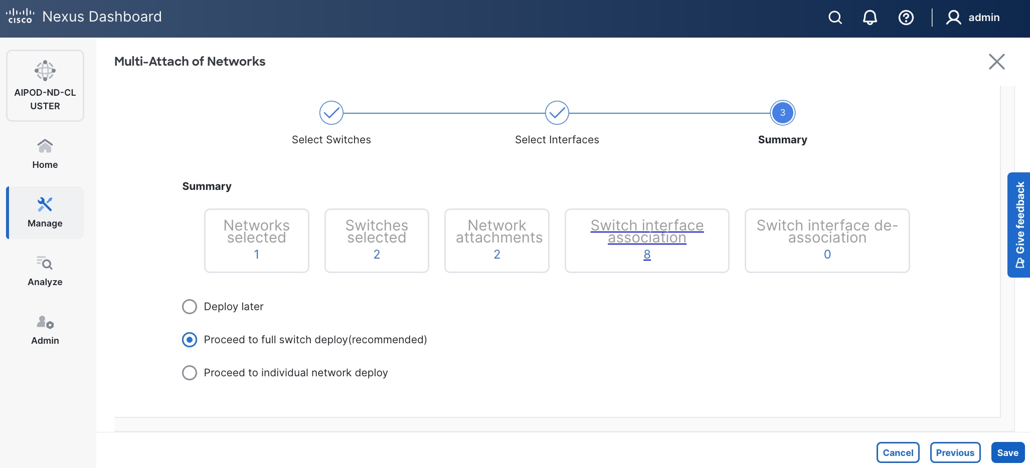
Step 14. Click Save.
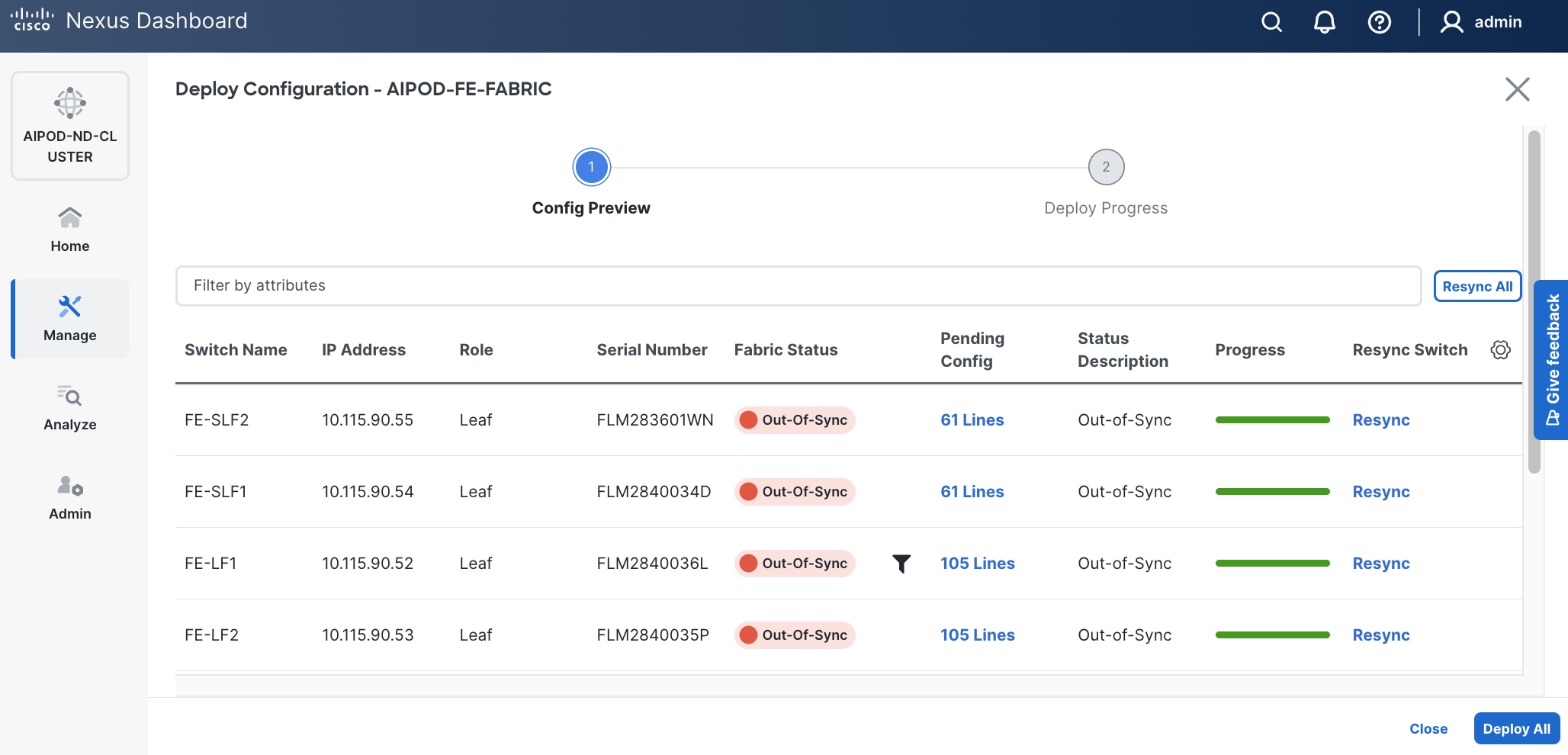
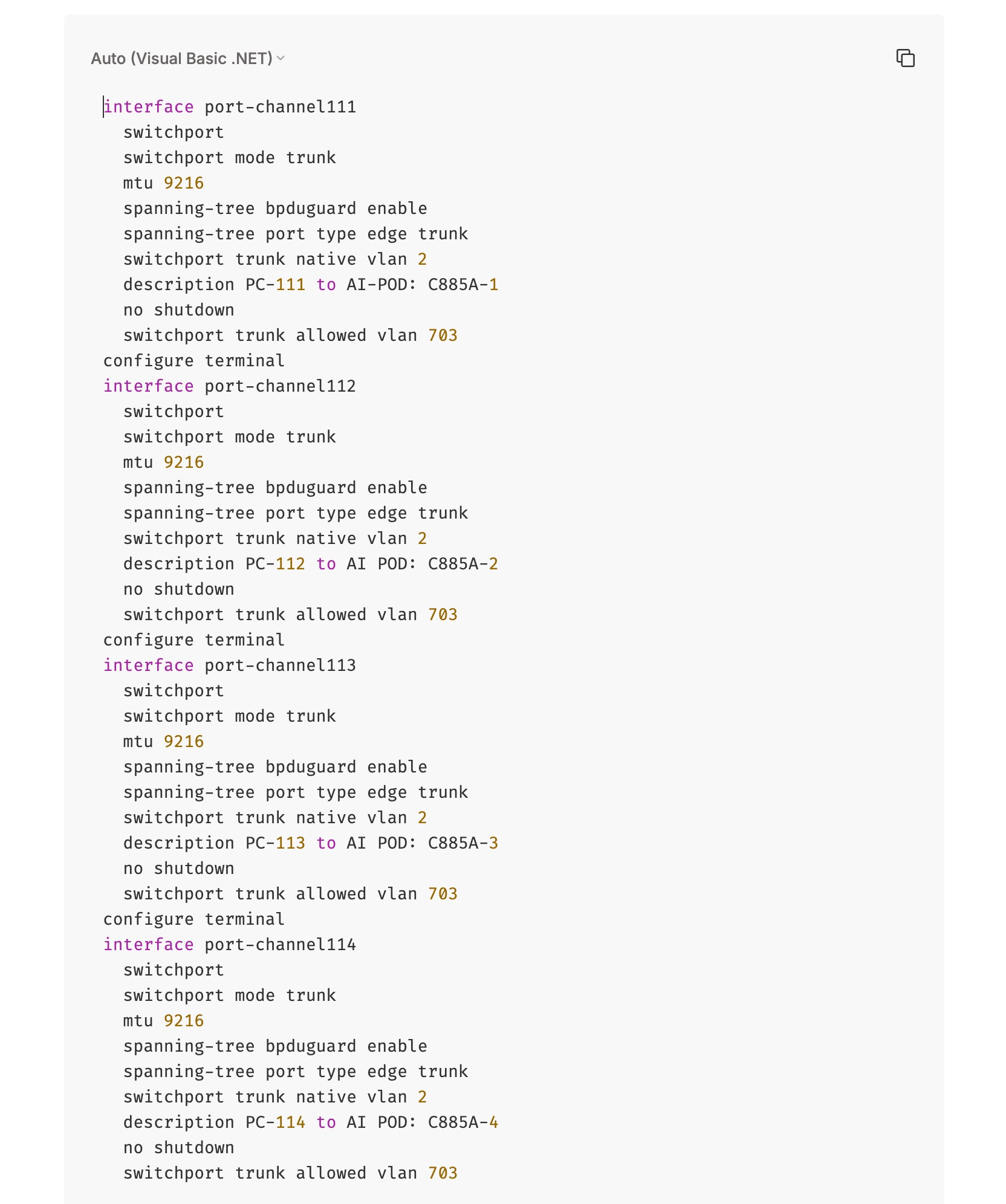
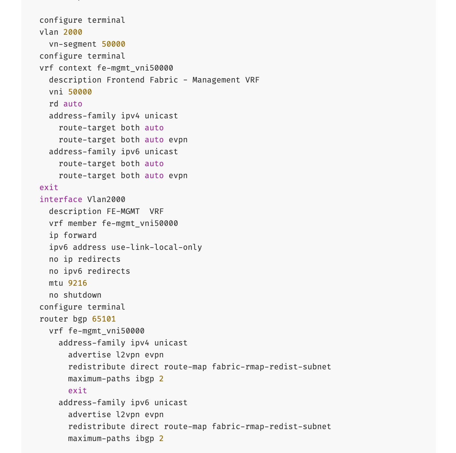
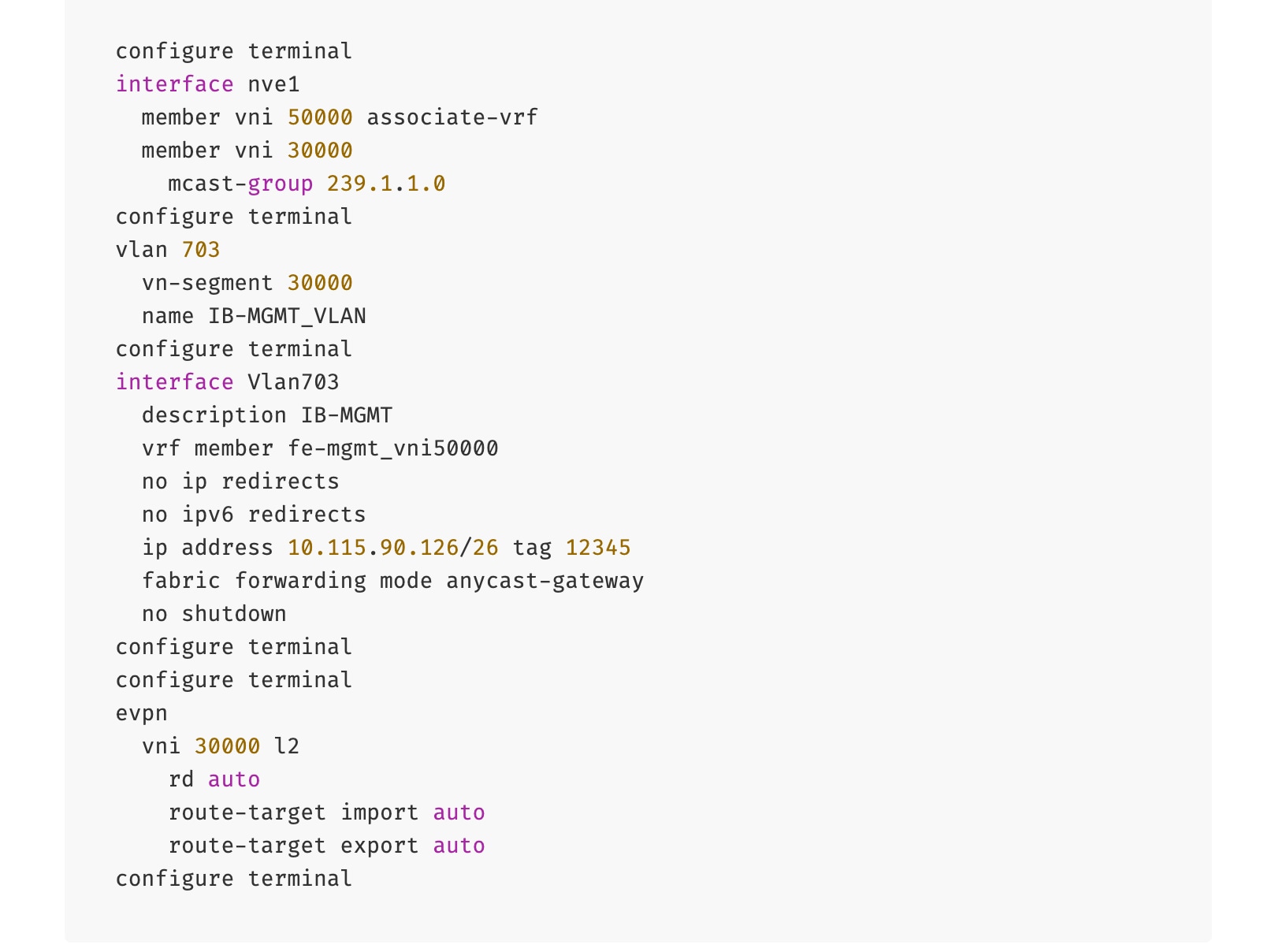
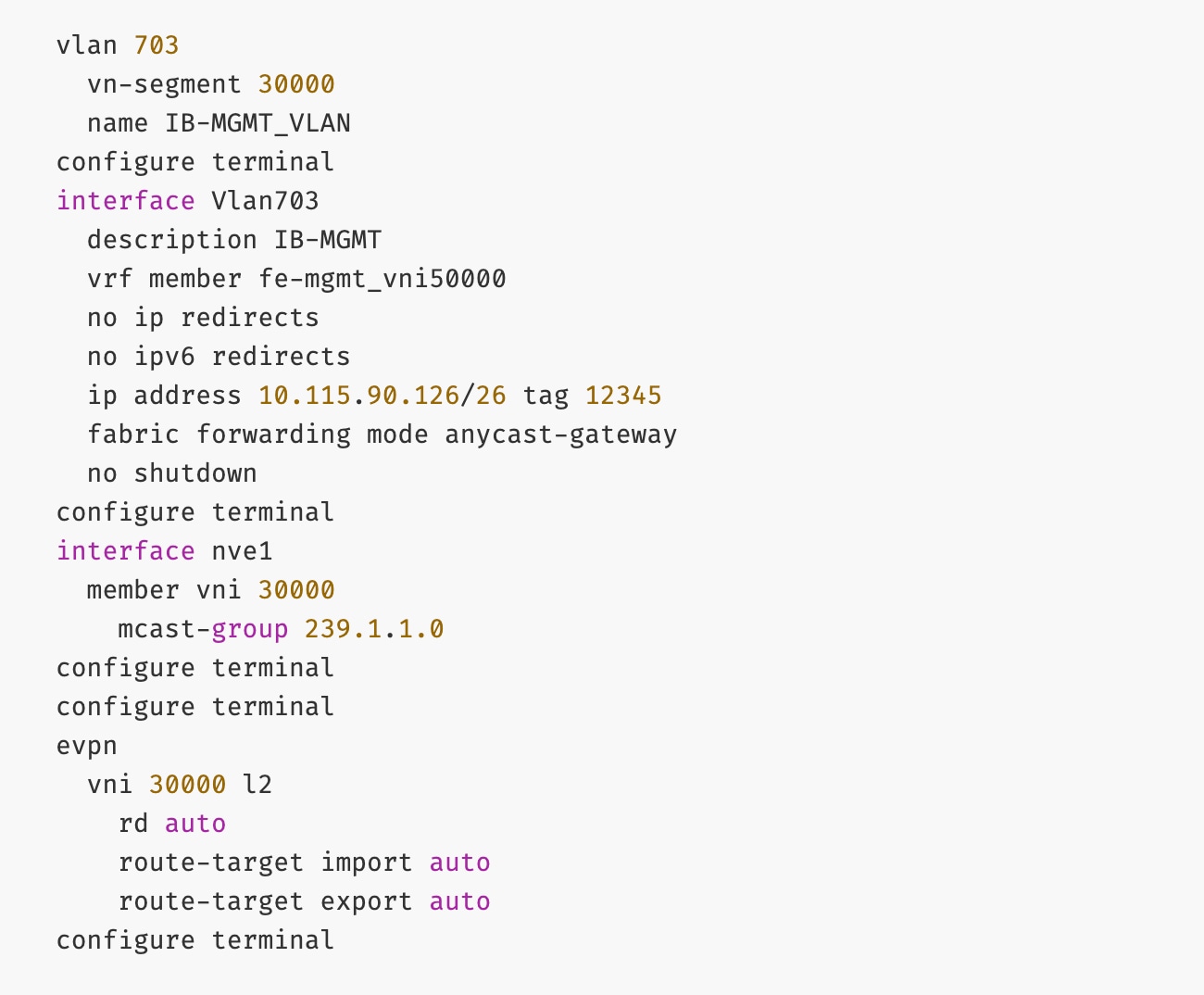
Step 15. Click Pending Config to see the configuration being deployed. The pending configuration on one leaf switch is provided as a reference at the end.
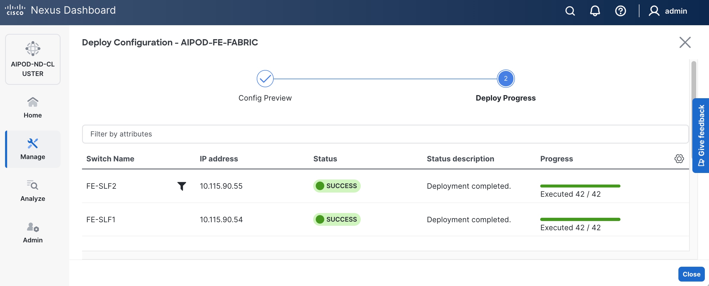
Step 16. Click Deploy All.
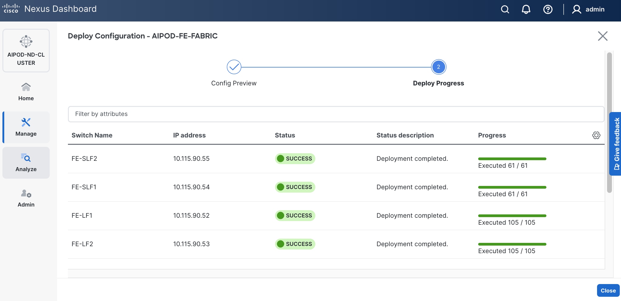
Step 17. Click Close.

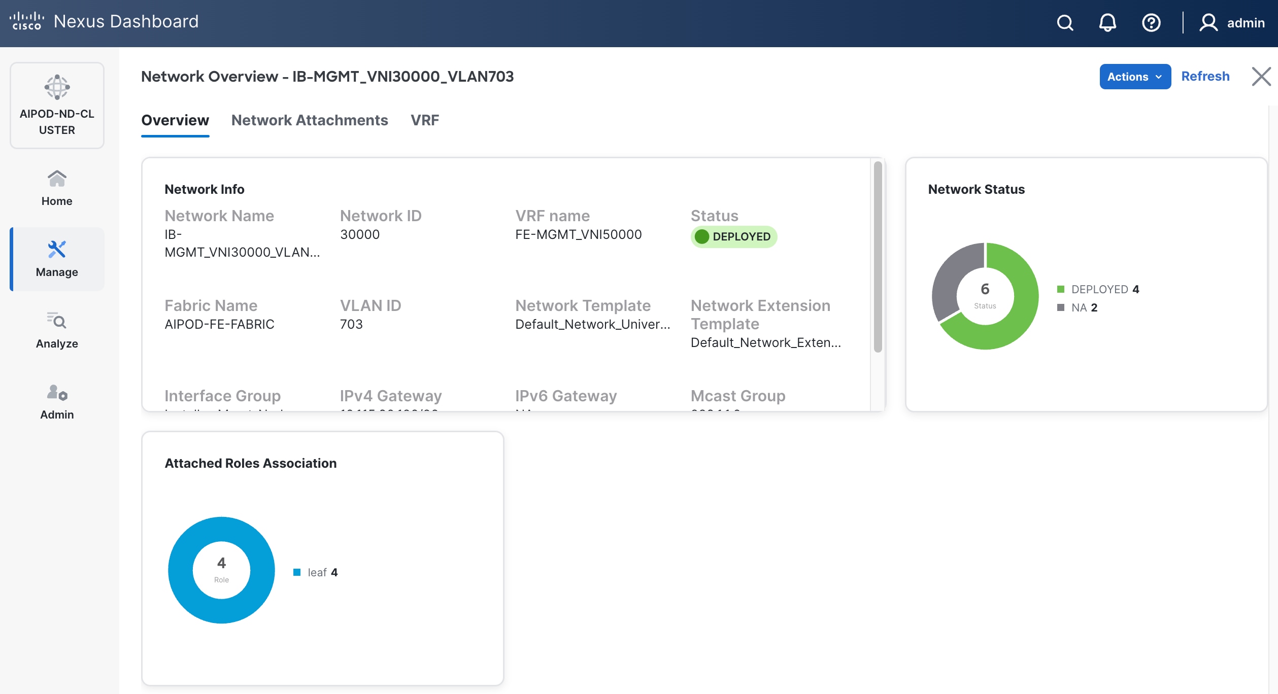
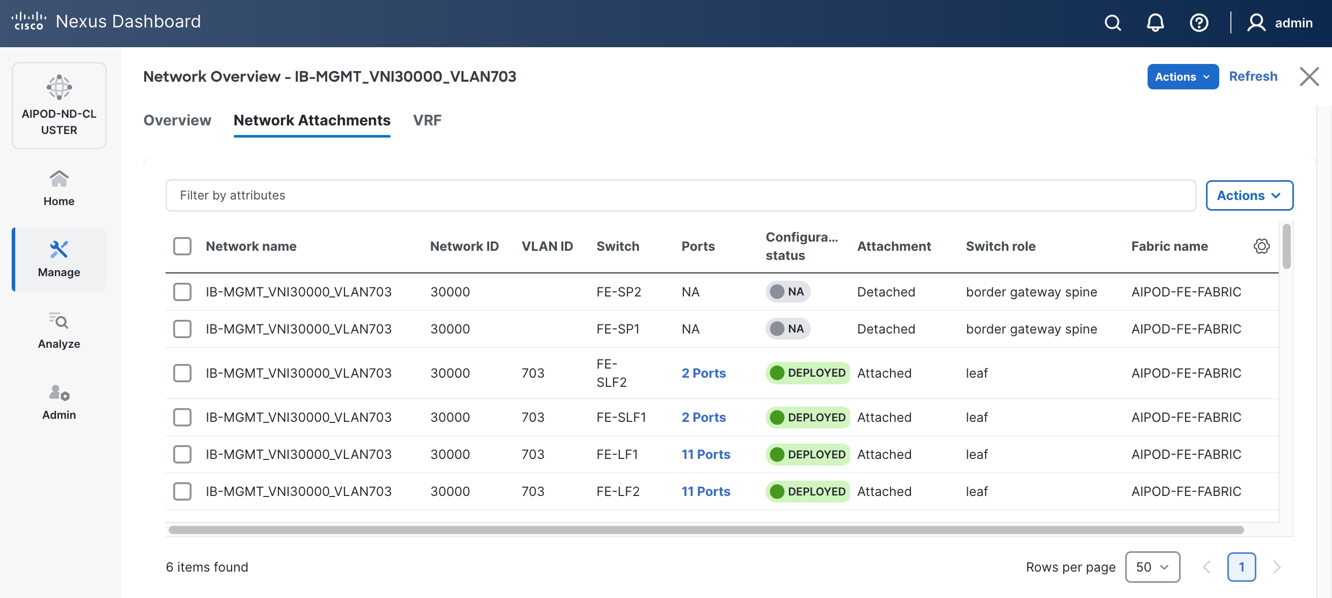
Step 18. Click the Network name to verify that the network was successfully deployed on the relevant switches and interfaces.

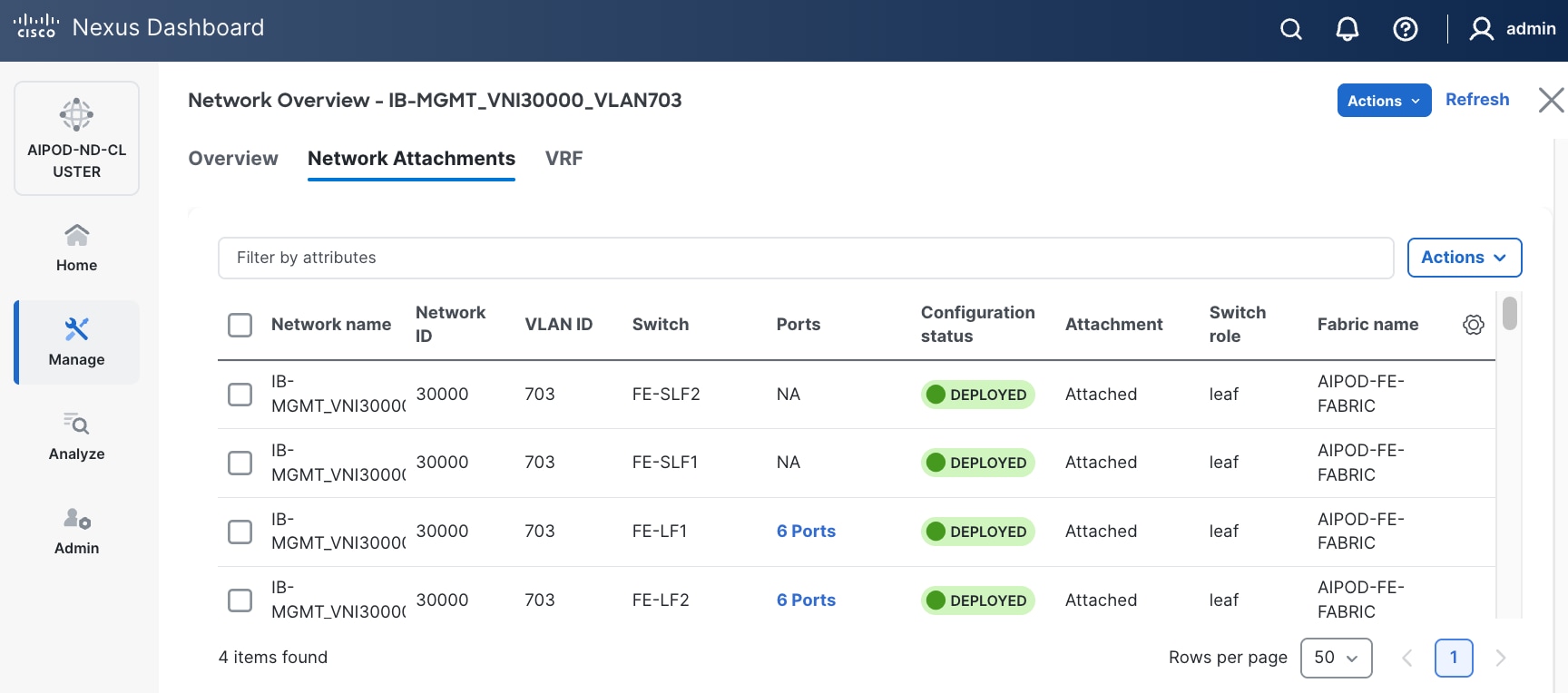
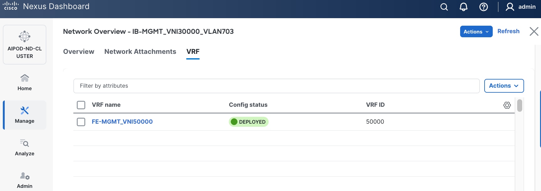
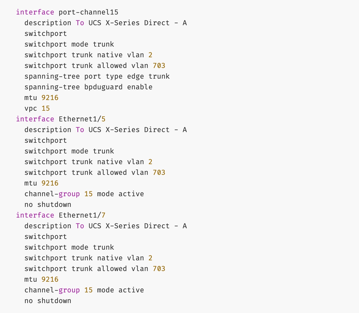
The configuration deployed on one compute leaf switch is provided below as a reference:
To deploy in-band management connectivity to Management UCS X-Series Direct on the compute leaf switches in the FE fabric, follow the procedures below.
Procedure 2. Deploy in-band management connectivity for management UCS X-Direct chassis
Step 1. Use a web browser to navigate to Nexus Dashboard. Use the management IP of any node in the ND cluster. Log in using admin account.
Step 2. From the left navigation menu, go to Manage > Fabrics.
Step 3. Select the FE fabric and navigate to Segmentation and Security > Networks tab.
Step 4. Select the previously deployed in-band management network from the list.

Step 5. Click the lower of the two Actions buttons and select Multi-attach from the list.
Step 6. Select the leaf switch pair from the list that the UCS X-Series Direct system connects to.
Step 7. Click Next.
Step 8. Click Select Interfaces to the right of the leaf switch pair to add the interfaces that connect to management UCS X-Series Direct.
Step 9. Click Next.
Step 10. Click Save.
Step 11. Click Deploy All.
Step 12. Click Close.
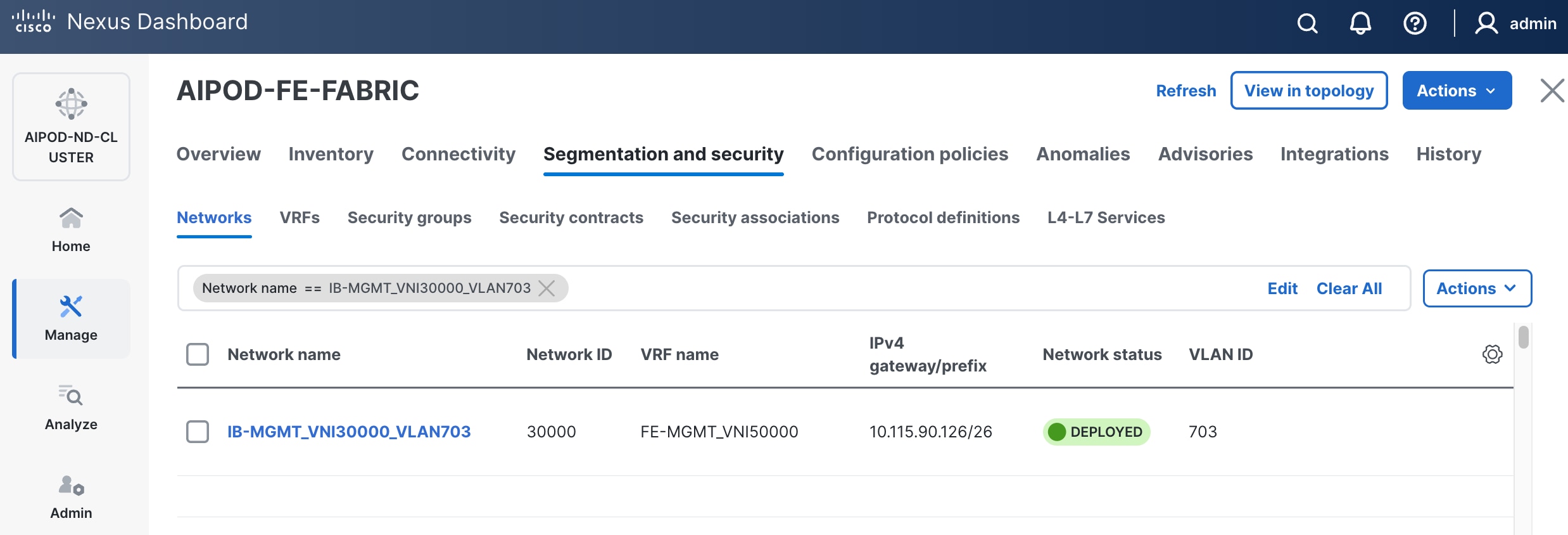
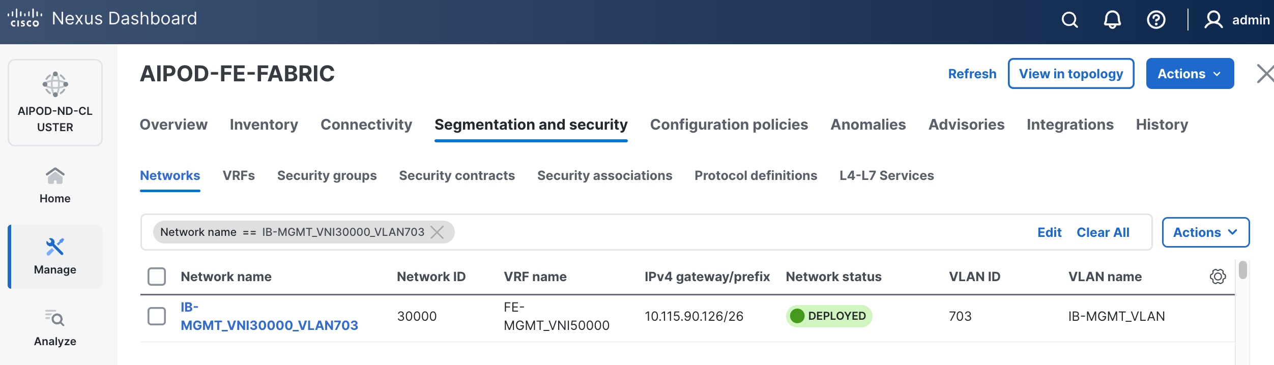
Step 13. Click the Network name to verify that the network was successfully deployed on the relevant switches and interfaces.
The configuration deployed on one compute leaf switch is provided below as a reference:
(Ubuntu) Enable In-Band Management Connectivity to BCM Node(s)
To deploy in-band management connectivity to BCM node connected to compute leaf switches in the FE fabric, you will be deploying this network on the compute Leaf switch pair that connects to the BCM node.
Table 13. Setup Parameters for FE Fabric: In-Band Management Connectivity to BCME Nodes
| Parameter Type |
Parameter Name | Value |
Parameter Type |
| IB-MGMT Network |
|
|
| Name |
IB-MGMT_VN30000_VLAN703 |
|
| IB-MGMT VRF |
|
|
| VRF Name |
FE-MGMT_VN50000 |
|
| Management BCME Node |
|
|
| vPC Leaf Switch Pair |
FE-LF1, FE-LF2 |
|
| BCM Interface |
Port-Channel 17 |
|
To deploy in-band management connectivity to BCM node connected to compute leaf switches in the FE fabric, complete the procedures below.
Procedure 1. Enable in-band management connectivity to BCM node
Step 1. Use a web browser to navigate to Nexus Dashboard. Use the management IP of any node in the ND cluster. Log in using admin account.
Step 2. From the left navigation menu, go to Manage > Fabrics.
Step 3. Select the FE fabric and go to Segmentation and Security > Networks tab.
Step 4. Select the previously deployed in-band management network from the list.
Step 5. Click the lower of the two Actions buttons and select Multi-attach from the list.

Step 6. Select the leaf switch pair from the list that the BCME node connects.
Step 7. Click Next.
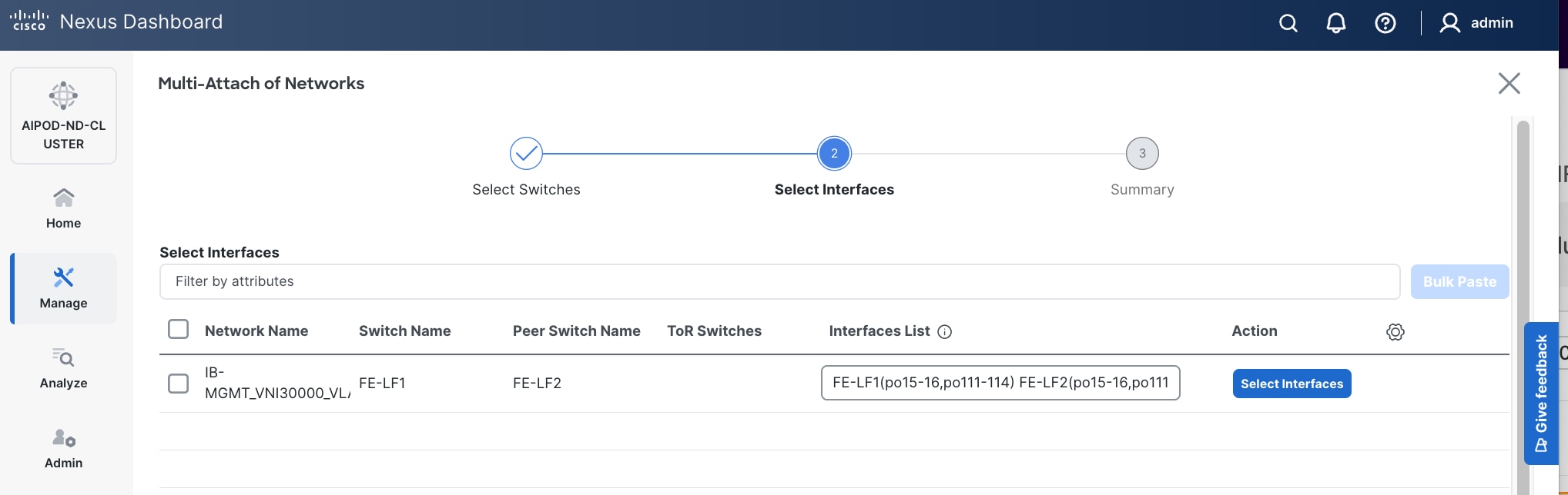
Step 8. Click Select Interfaces to the right of the network name to add the interfaces that connect to the BCM node.
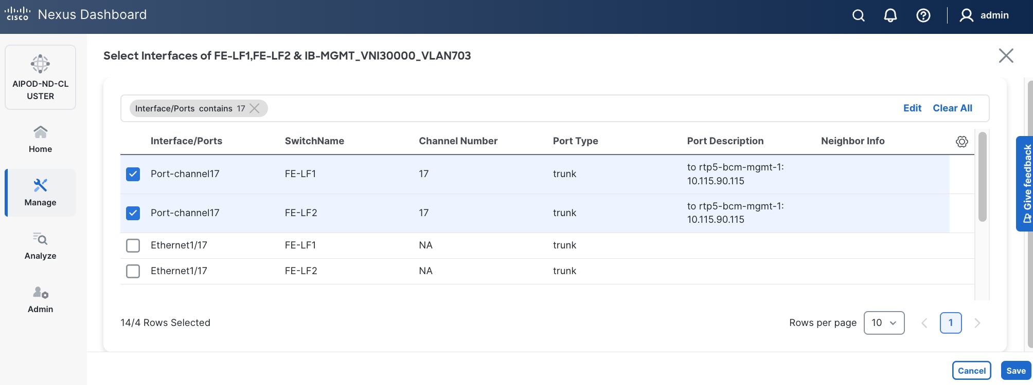
Step 9. Click Save.
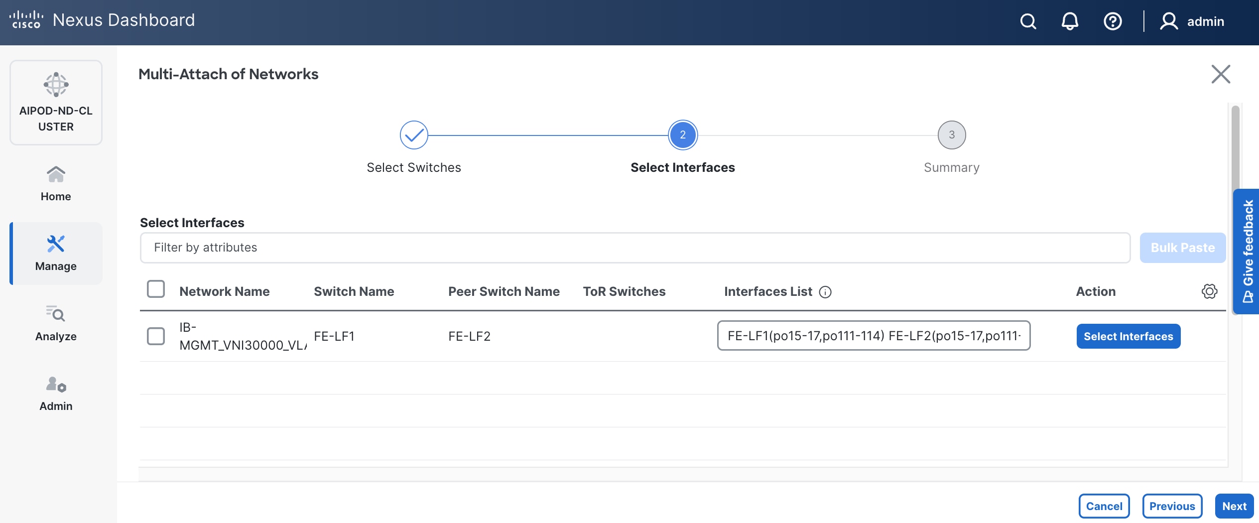
Step 10. Click Next.
Step 11. Click Save.
The configuration deployed on one compute leaf switch is provided below as a reference:
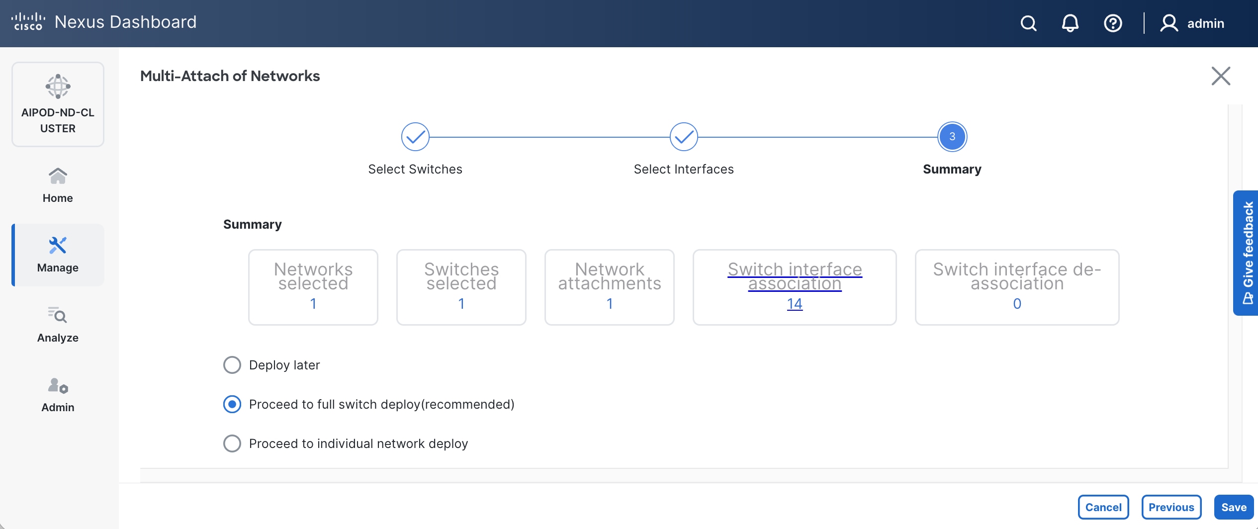
Step 12. Click Deploy All.
Step 13. Click Close.

Step 14. Click the Network name to verify that the network was successfully deployed on the relevant switches and interfaces.
Enable Layer 2 Connectivity to NetApp Storage
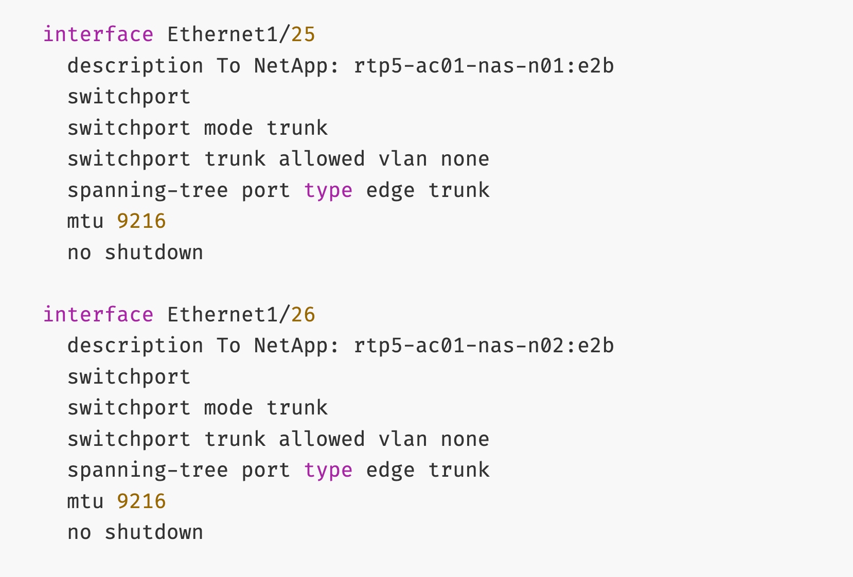
To enable Layer 2 connectivity from the FE fabric to NetApp storage, you will be configuring four ports, two on each Leaf switch. Each port is configured as a trunk port using the default native VLAN.
Table 14. Setup Parameters for FE Fabric: Layer 2 Connectivity to NetApp Storage
| Parameter Type |
Parameter Name | Value |
Parameter Type |
| Leaf Switches |
FE-SLF1, FE-SLF2 |
|
| NetApp Storage |
|
To Storage Leaf Switches |
| FE-SLF1 |
|
|
| Ports |
1/25 |
|
| Ports |
1/26 |
|
| FE-SLF2 |
|
|
| Ports |
1/25 |
|
| Ports |
1/26 |
|
To enable Layer 2 connectivity from the FE fabric to NetApp storage, follow the procedures below.
Procedure 2. Enable Layer 2 connectivity on the first port to NetApp storage
Step 1. Use a web browser to navigate to Nexus Dashboard. Use the management IP of any node in the ND cluster. Log in using admin account.
Step 2. From the left navigation menu, go to Manage > Fabrics.
Step 3. Select the FE fabric and go to Connectivity > Interfaces tab.
Step 4. Filter on the storage leaf switches and the ports that connect to NetApp storage.
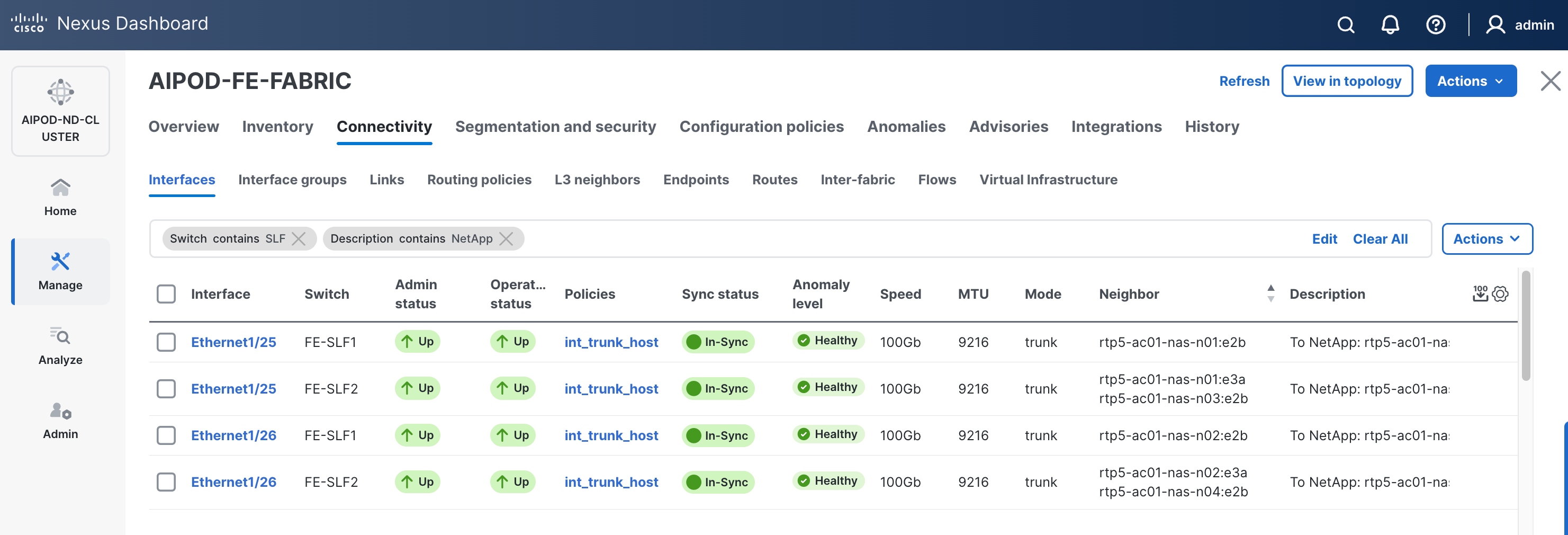
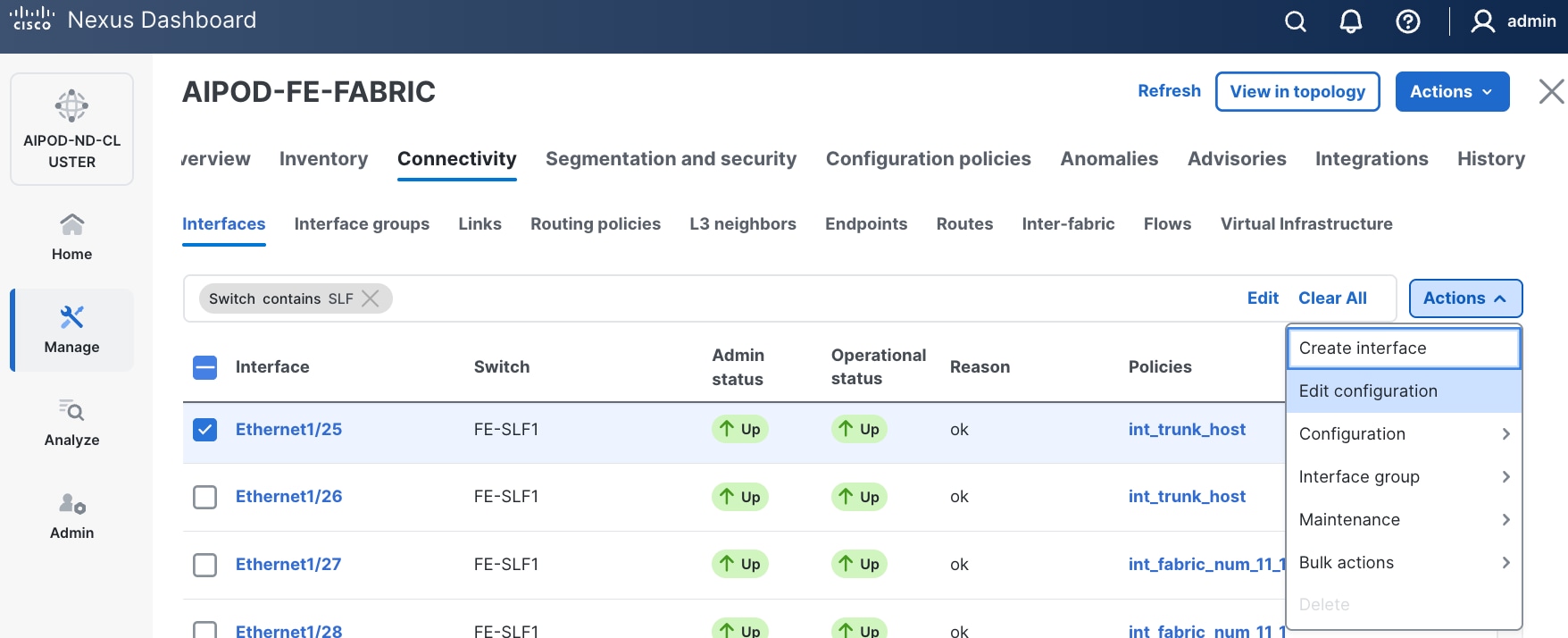
Step 5. Select the first interface to configure from the list.
Step 6. Click the lower of the two Actions buttons and select the Edit configuration from the drop-down list.
Step 7. In the Edit interface window, configure Interface Description and leave everything else as is.
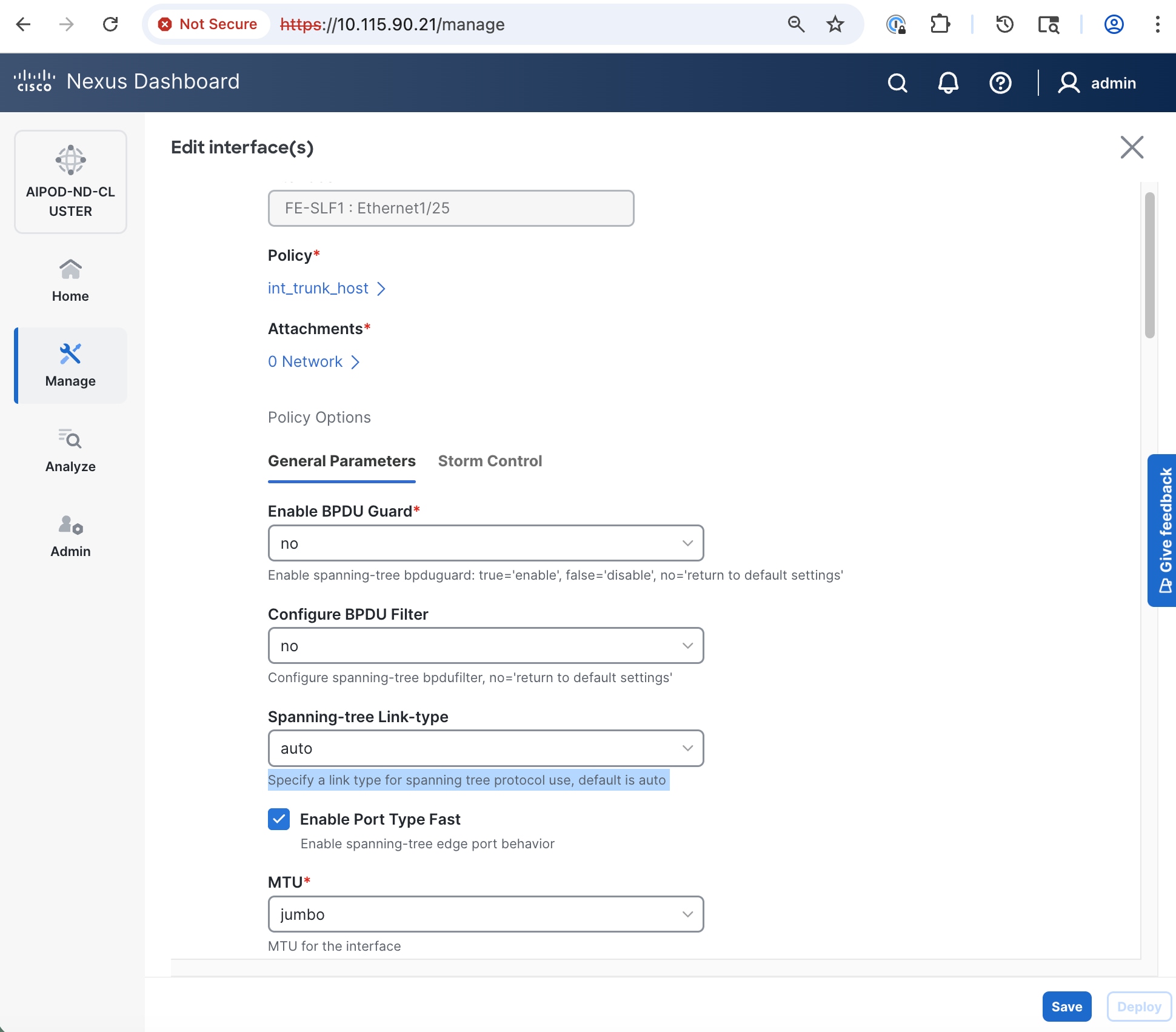
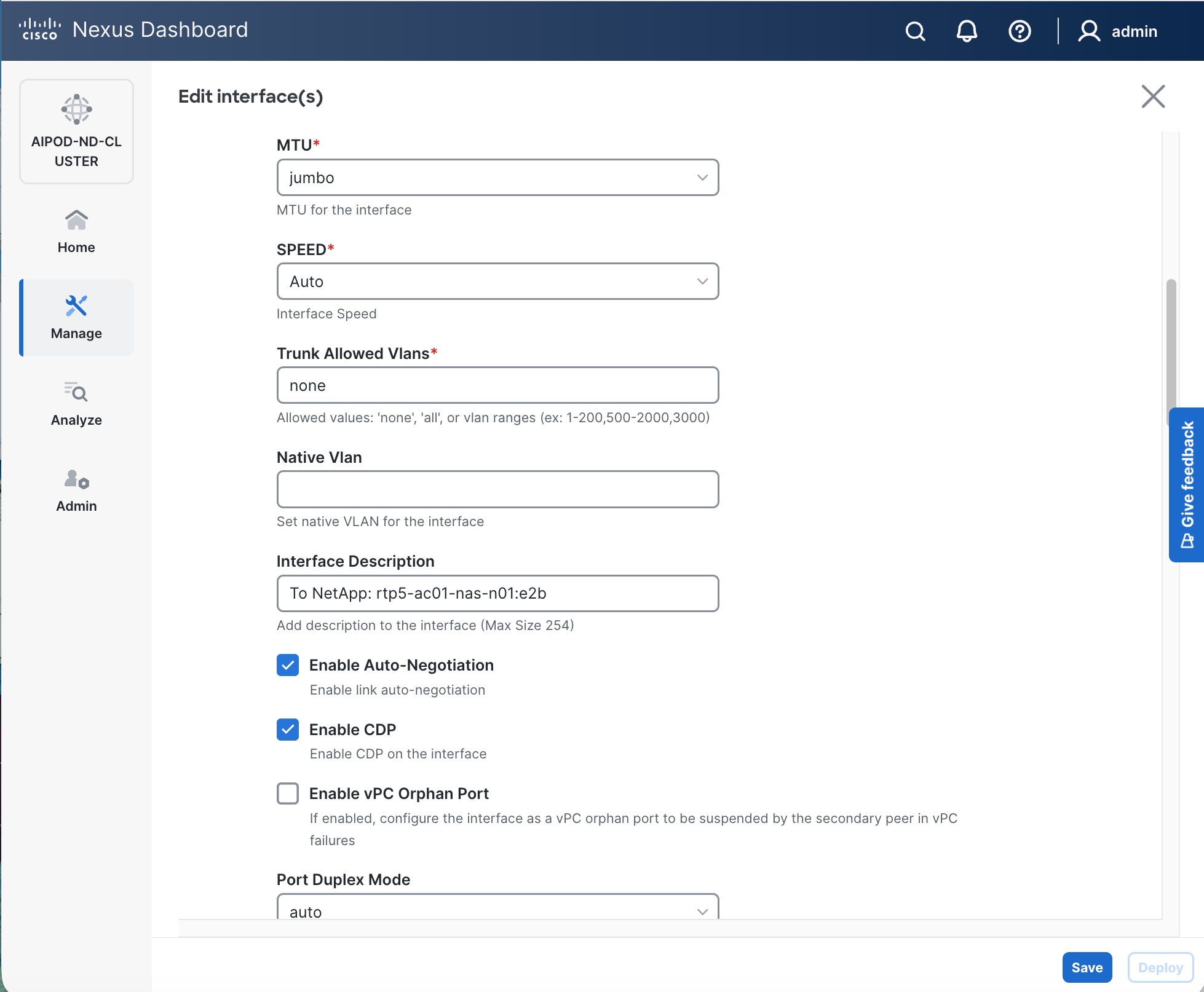
Step 8. Click Save.
Step 9. Click X to exit the window (changes will be deployed later).
Step 10. Repeat for remaining ports on both storage leaf switches that connect to NetApp storage.
Step 11. Navigate to Manage > Inventory. Select the two storage Leaf switches and click the lower of the two Actions button.
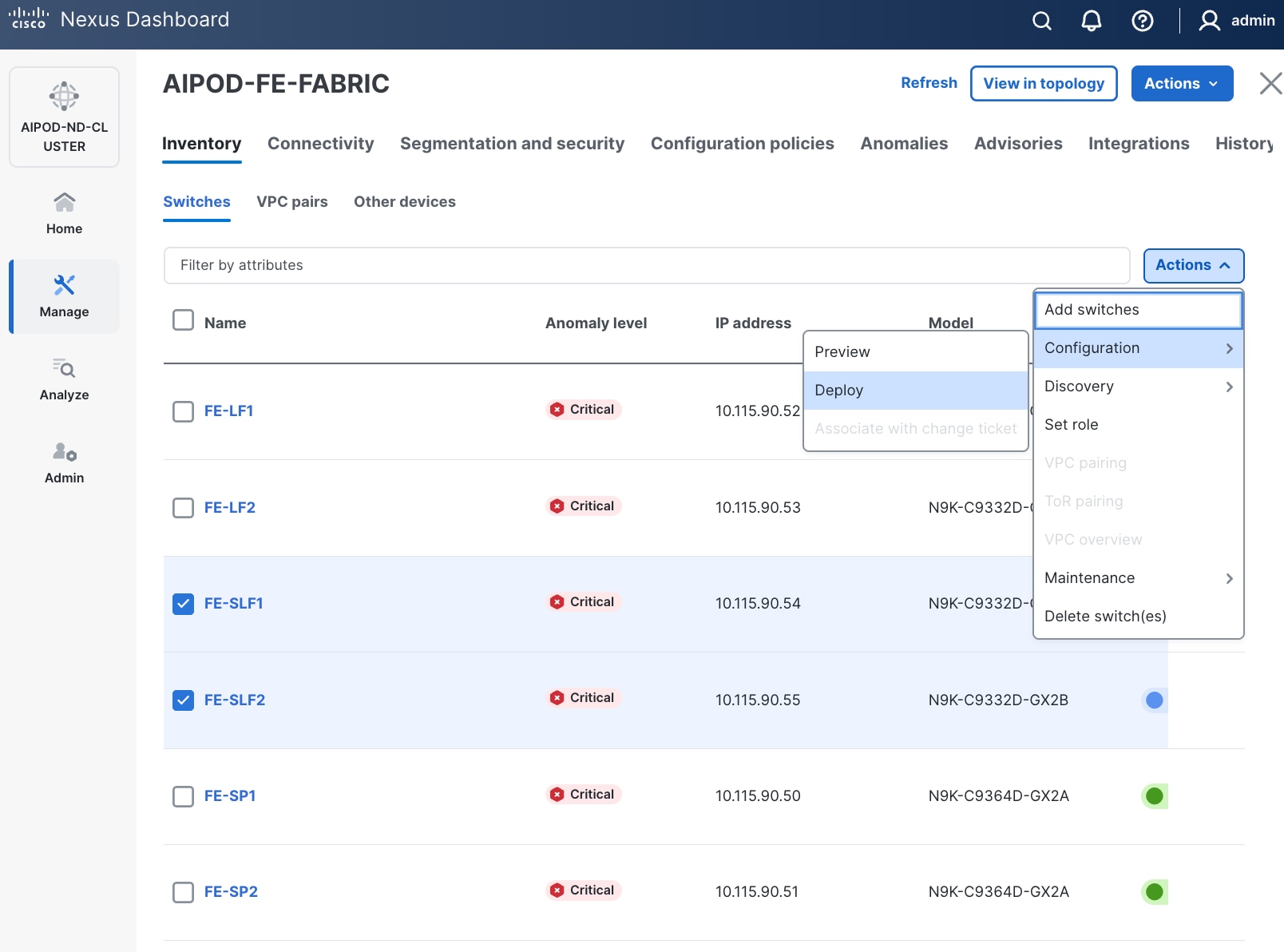
Step 12. Select Configuration > Deploy from the drop-down list.
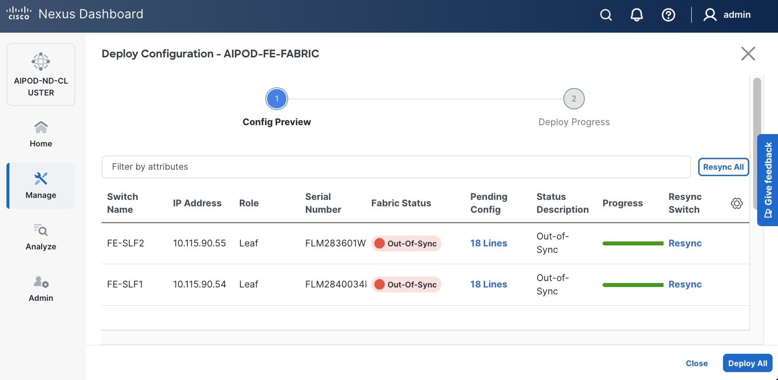
Step 13. Click Pending Config for each switch to see the configuration that will be deployed on each switch. The deployed configuration from one leaf switch is provided as reference below.
Step 14. Click Deploy All.
Step 15. Click Close.
Enable In-Band Management Connectivity to NetApp Storage
Table 15. Setup Parameters for FE Fabric: In-Band Management Connectivity to NetApp Storage
| Parameter Type |
Parameter Name | Value |
Parameter Type |
| IB-MGMT Network |
|
|
| Name |
IB-MGMT_VN30000_VLAN703 |
|
| NetApp Storage |
|
On Storage Leaf Switches |
| Storage Leaf Switch |
FE-SLF1 |
|
| Port |
e1/25 |
|
| Port |
e1/26 |
|
| Storage Leaf Switch |
FE-SLF2 |
|
| Port |
e1/25 |
|
| Port |
e1/26 |
|
Procedure 1. Deploy In-Band Management Connectivity for NetApp storage
Step 1. Use a web browser to navigate to Nexus Dashboard. Use the management IP of any node in the ND cluster. Log in using admin account.
Step 2. From the left navigation menu, go to Manage > Fabrics.
Step 3. Select the FE fabric and go to Segmentation and Security > Networks tab.
Step 4. Select the previously deployed in-band management network from the list.
Step 5. Click the lower of the two Actions buttons and select Multi-attach from the drop-down list.
Step 6. Deploy the network on the storage leaf switch pair.
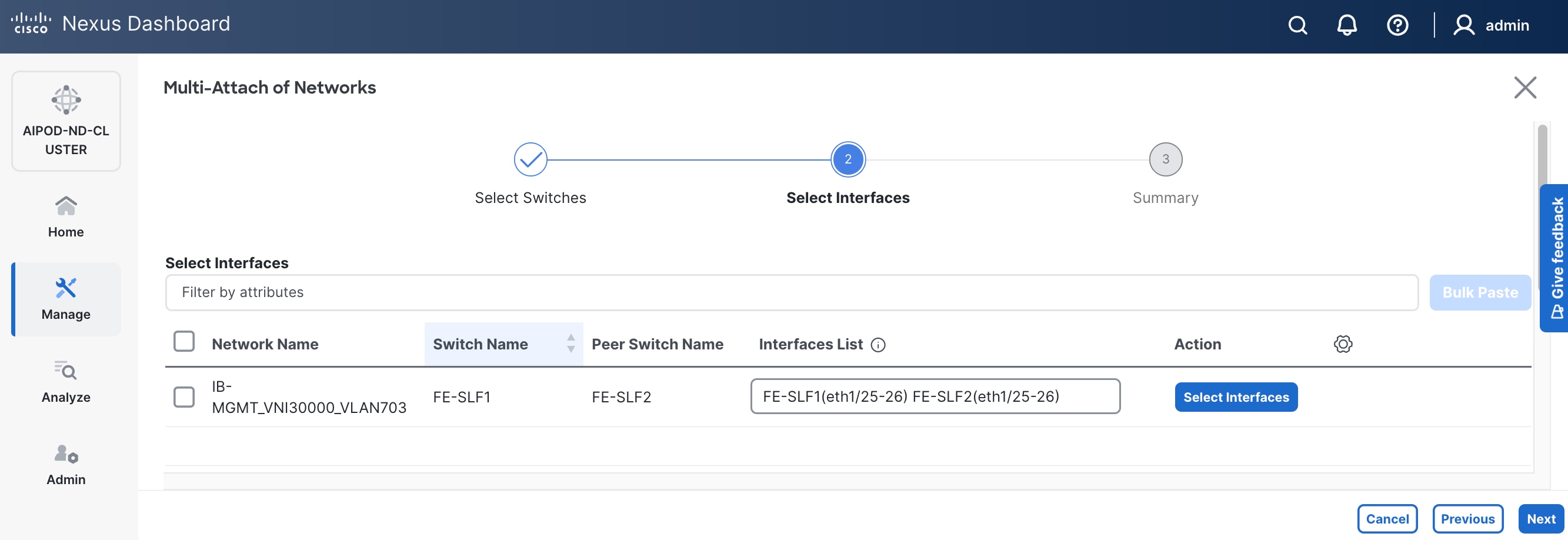
Step 7. Click Next.
Step 8. Select the network and click Select interfaces on the right.
Step 9. Select the interfaces from the list.
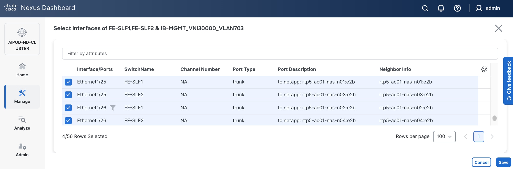
Step 10. Click Save.
Step 11. Click Next.
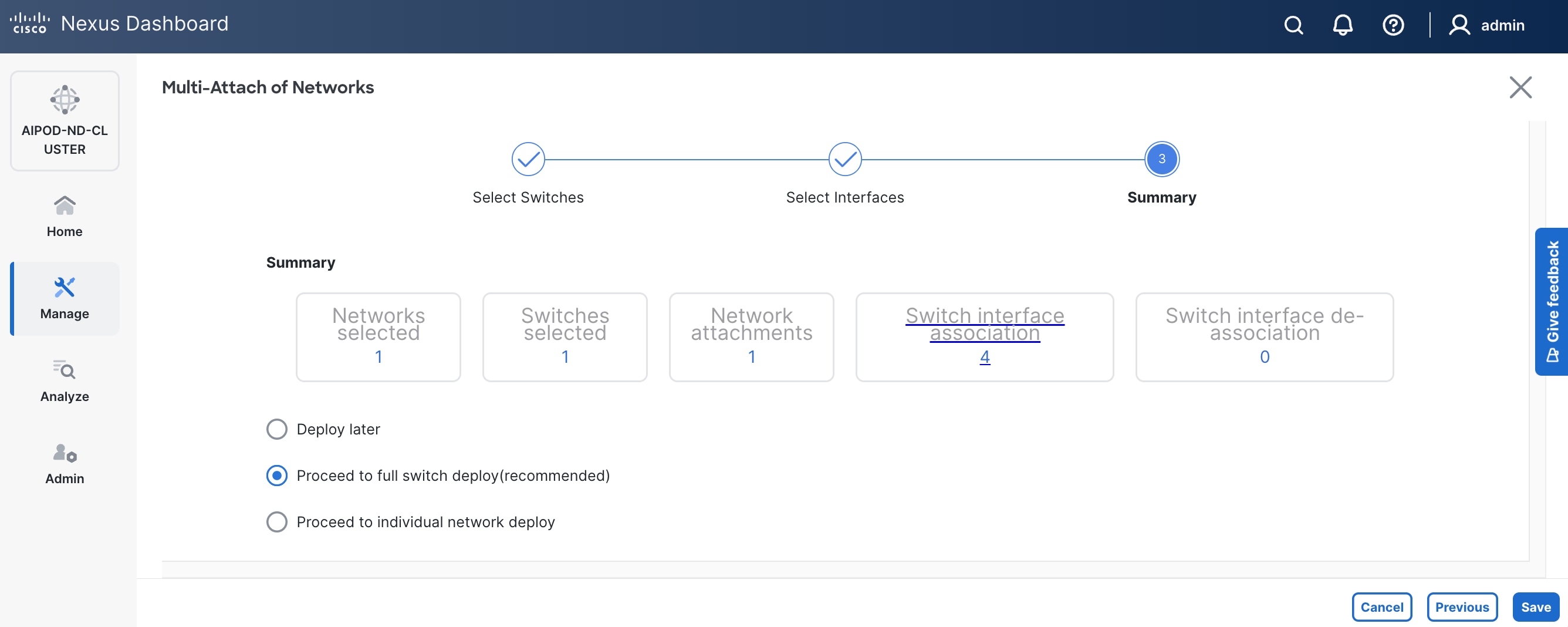
Step 12. Click Save.
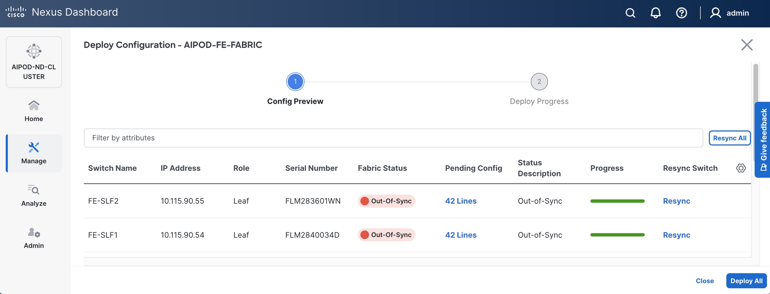
Step 13. Click Pending Config to see the configuration being deployed. The pending configuration on one leaf switch is provided as a reference at the end.
Step 14. Click Deploy All.
Step 15. Click Close.
Step 16. Click the Network name to verify that the network was successfully deployed on the relevant switches and interfaces.
Step 17. Verify the status and that the network is deployed.
The configuration deployed on one storage leaf switch is provided below as a reference:
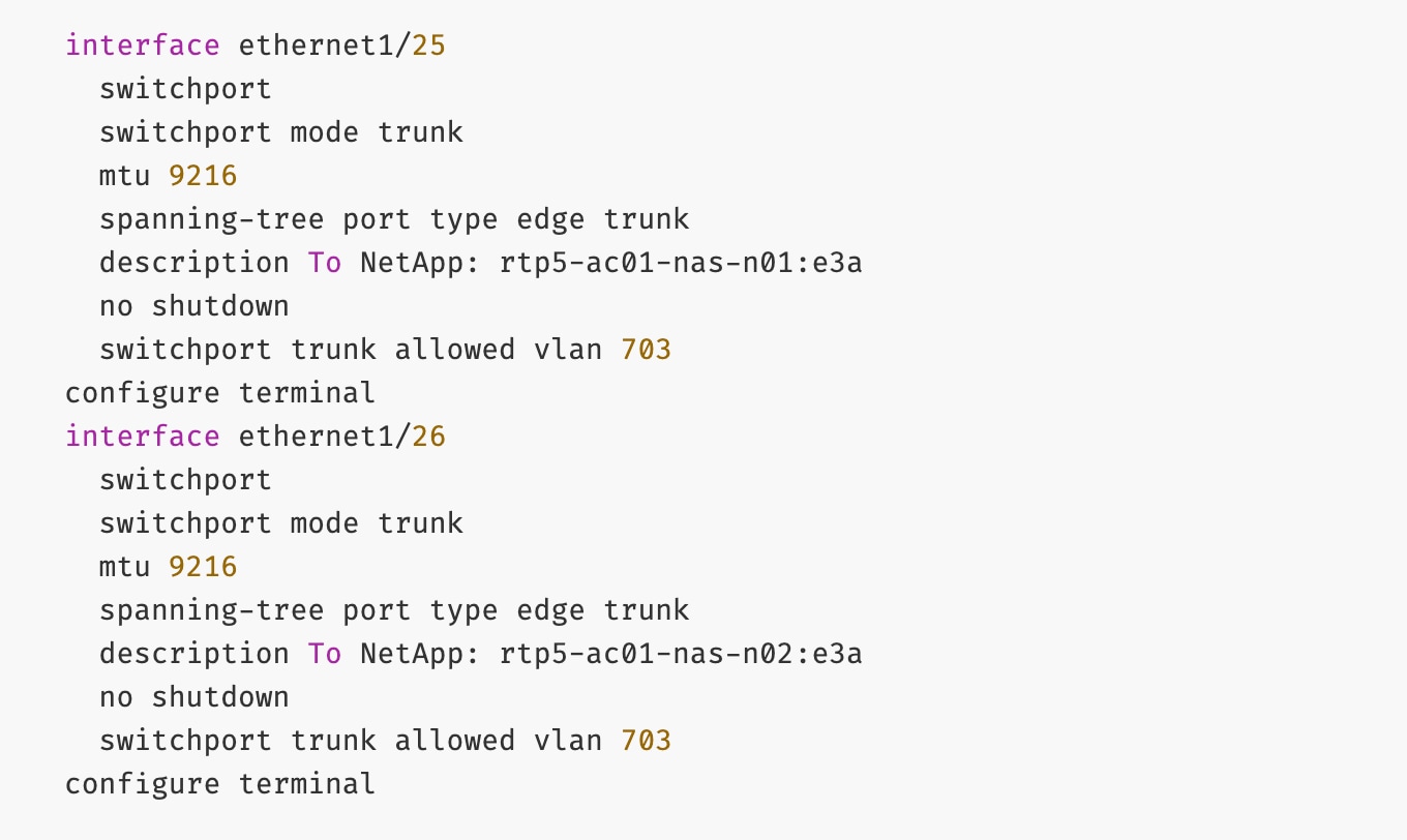
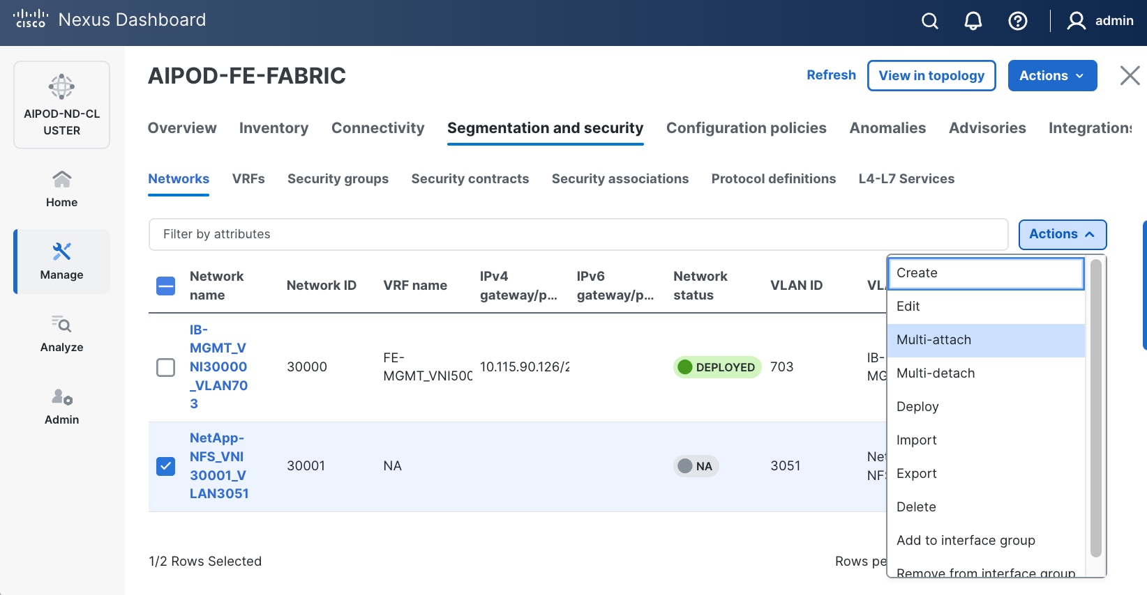
Enable NFS Storage Data Access to NetApp Storage
Table 16. Setup Parameters for FE Fabric: NFS Storage Data Access to NetApp Storage
| Parameter Type |
Parameter Name | Value |
Parameter Type |
| NFS Storage Data Network(s) |
|
|
| Name |
NetApp-NFS_VN30001_VLAN3051 |
|
| Layer 2 Only |
Enable checkbox |
|
| Network ID |
30001 |
|
| VLAN ID |
3051 |
|
| VLAN Name |
NetApp-NFS_VLAN3051 |
|
| Interface Description |
NetApp-NFS |
|
| Name |
NetApp-NFS_VN30002_VLAN3052 |
|
| Layer 2 Only |
Enable checkbox |
|
| Network ID |
30002 |
|
| VLAN ID |
3052 |
|
| VLAN Name |
NetApp-NFS_VLAN3052 |
|
| Interface Description |
NetApp-NFS |
|
| NetApp Storage |
|
|
| vPC Leaf Switch Pair |
FE-SLF1, FE-SLF2 |
|
| Port |
e1/25 - 26 |
|
| Leaf Switch Pair |
FE-LF1, FE-LF2 |
|
| vPC |
15,16, 111-114 |
To Management UCS-X Direct, UCS C885A GPU Nodes |
| Port Channel |
15,16, 111-114 |
Members: e1/1-4 |
To enable NFS storage data access to NetApp storage, follow the procedures below.
Procedure 1. Enable NFS Storage Data Access to NetApp Storage using the first NFS VLAN
Step 1. Use a web browser to navigate to Nexus Dashboard. Use the management IP of any node in the ND cluster. Log in using admin account.
Step 2. From the left navigation menu, go to Manage > Fabrics.
Step 3. Select the FE fabric and go to Segmentation and Security > Networks tab.
Step 4. Click the lower of the two Actions buttons and select Create from the menu.
Step 5. In the Create Network window, specify the following:
● Network name
● Enable checkbox for Layer 2 only Layer 2 only.
● Network IDNetwork ID or use default.
● VLAN ID VLAN ID or click Propose VLAN Propose VLAN to let system define a VLAN.
● In the General Parameters tab, specify VLAN Name and Interface Description.
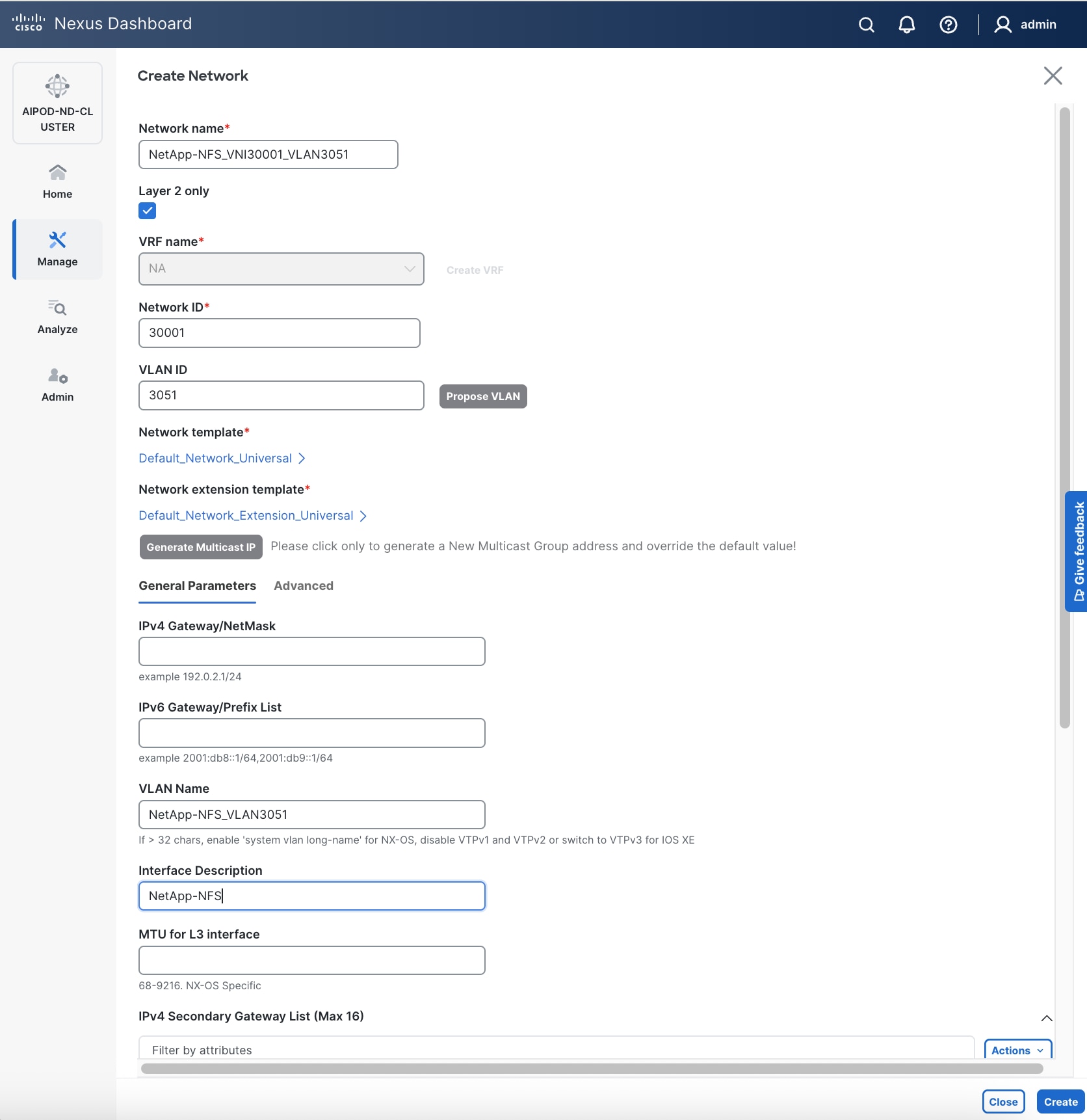
Step 6. Click Create to create the NFS Storage Data Network.
Step 7. Select newly created network. Click the lower of the two Actions button and select Multi-attach from the list.
Step 8. Select the compute and storage Leaf switch pairs.
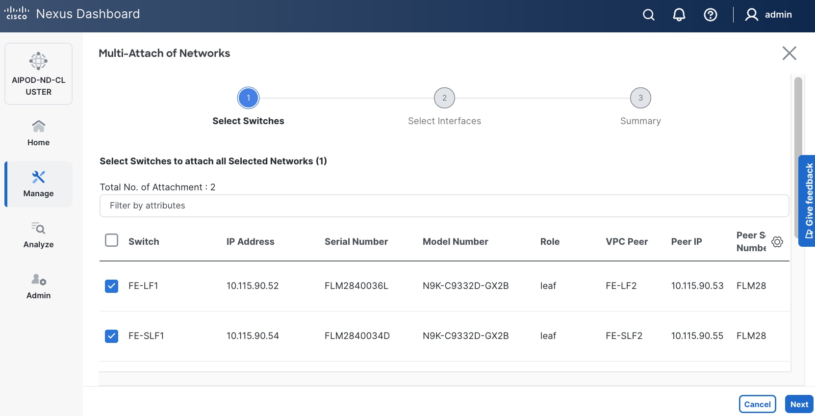
Step 9. Click Next.
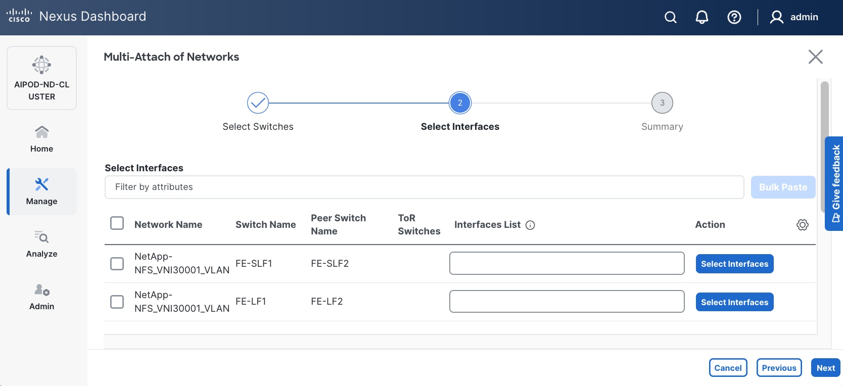
Step 10. Select each Network Name in the list and click Select interfaces on the right to deploy this network as a trunked VLAN on the selected interfaces. This should include the ports on the compute and storage leaf pair that connect to UCS nodes and NetApp storage, respectively. Additional interfaces can be added later as needed.
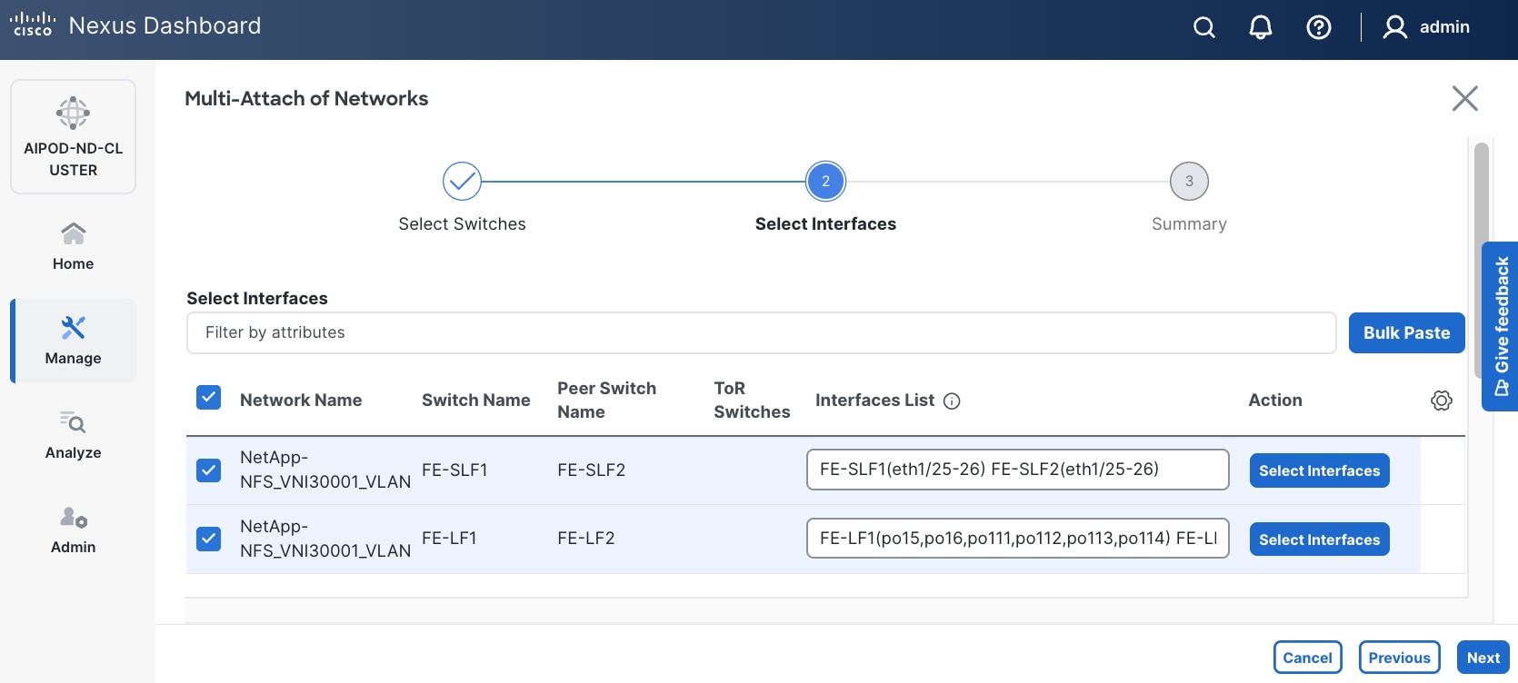
Step 11. Click Next.

Step 12. Click Save.
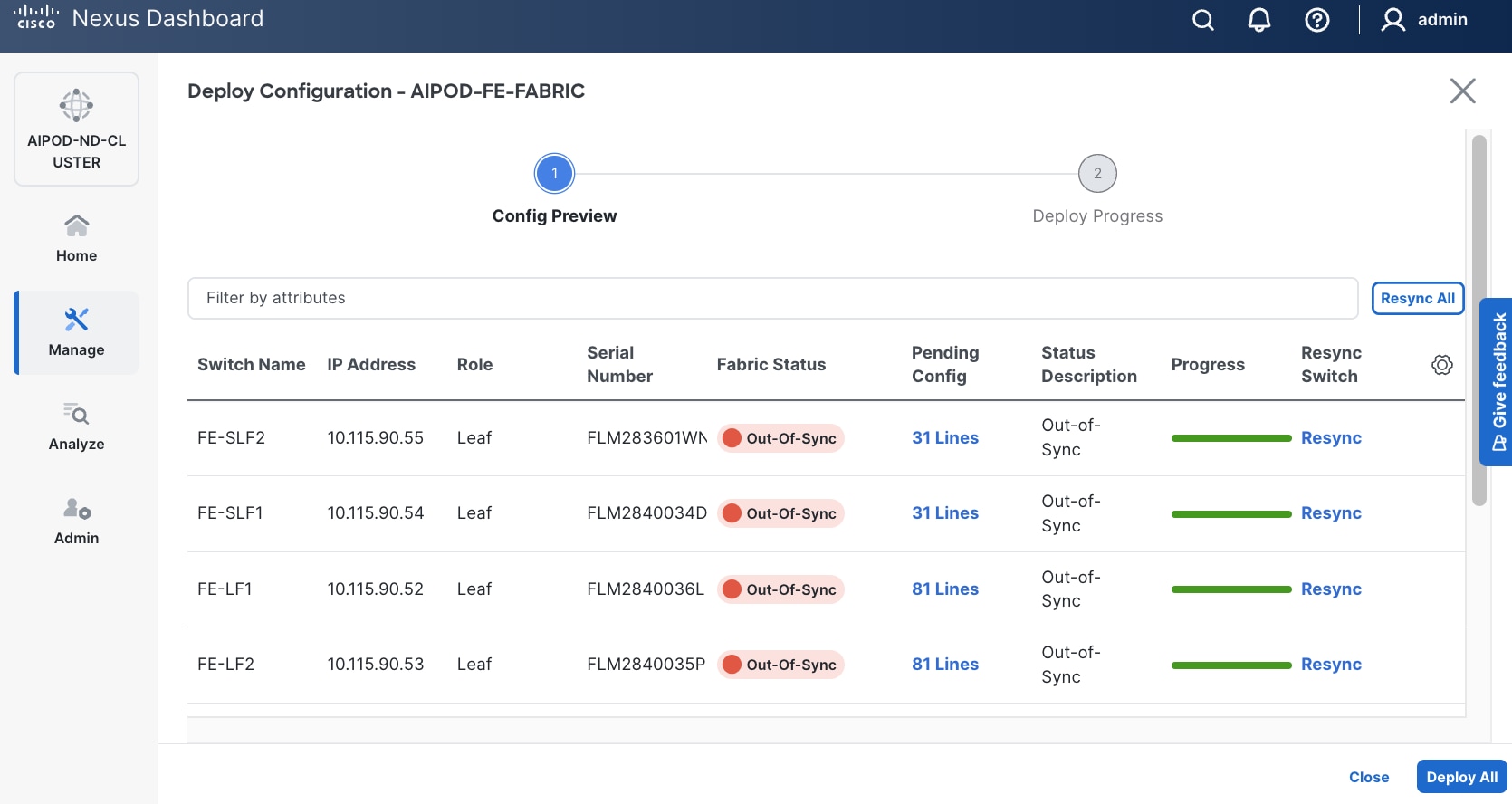
Step 13. Click Pending Config to see the configuration being deployed. The pending configuration on one leaf switch is provided as a reference at the end.
Step 14. Click Deploy All.
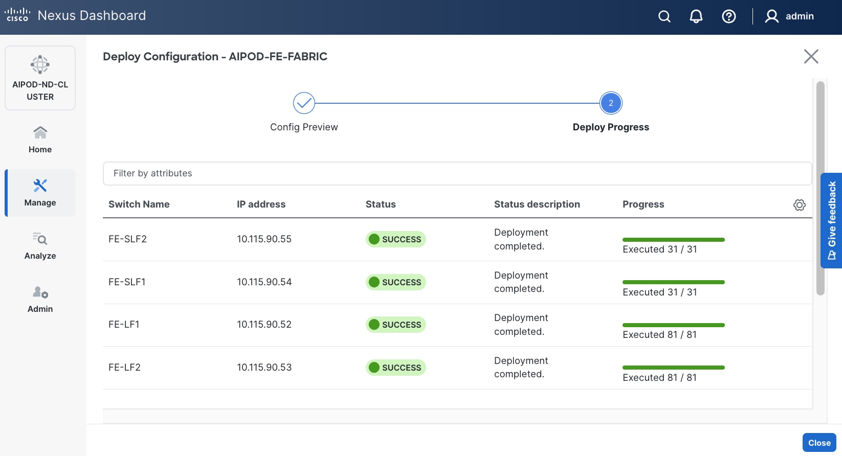
Step 15. Click Close.

Step 16. Click the Network name to verify that the network was successfully deployed on the relevant switches and interfaces.
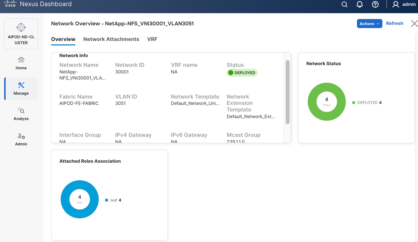
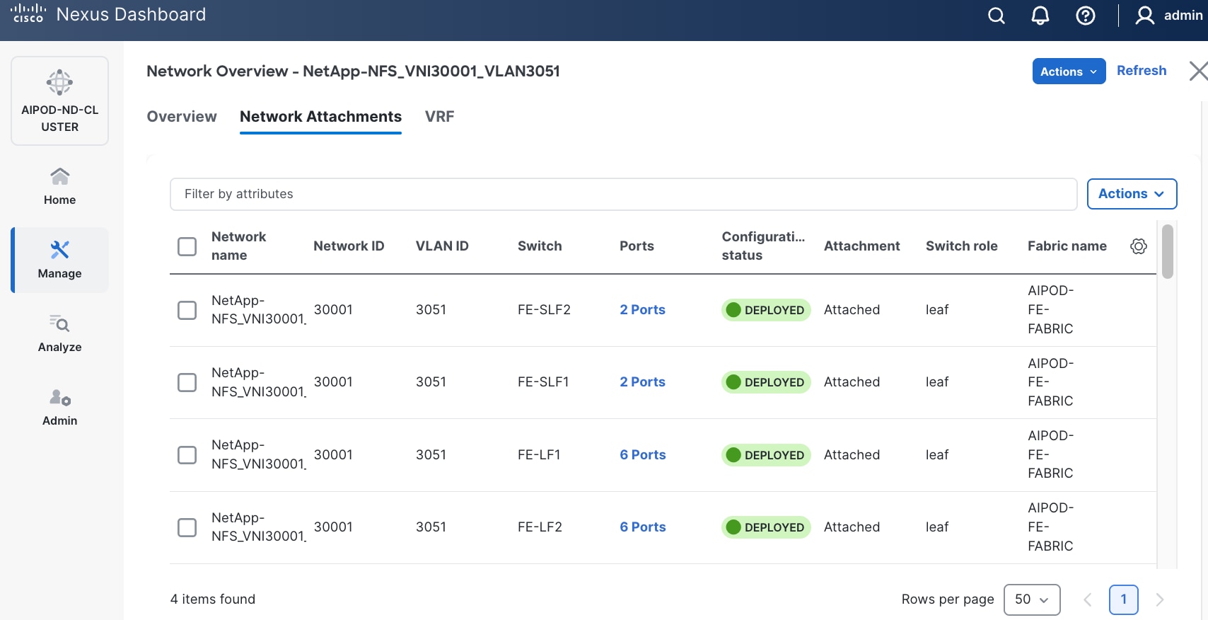
Step 17. The configuration deployed on one storage and compute leaf switch is provided below as a reference:
● StorageStorage Leaf
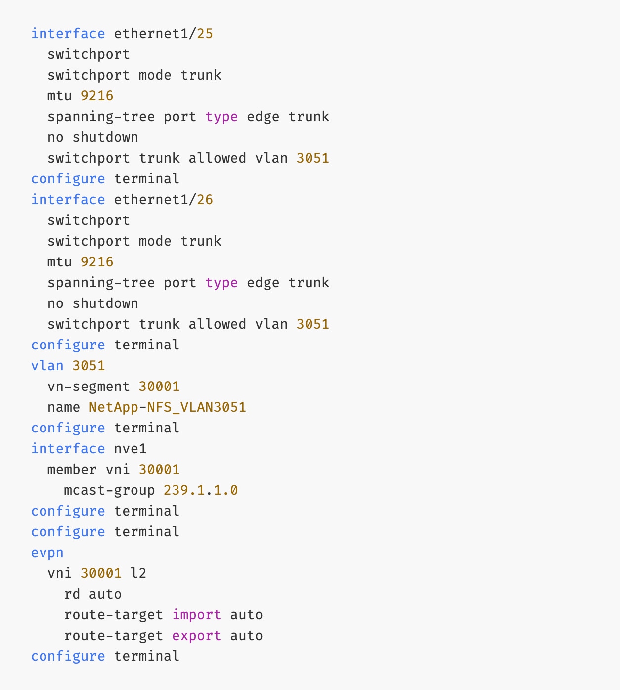
● ComputeCompute Leaf
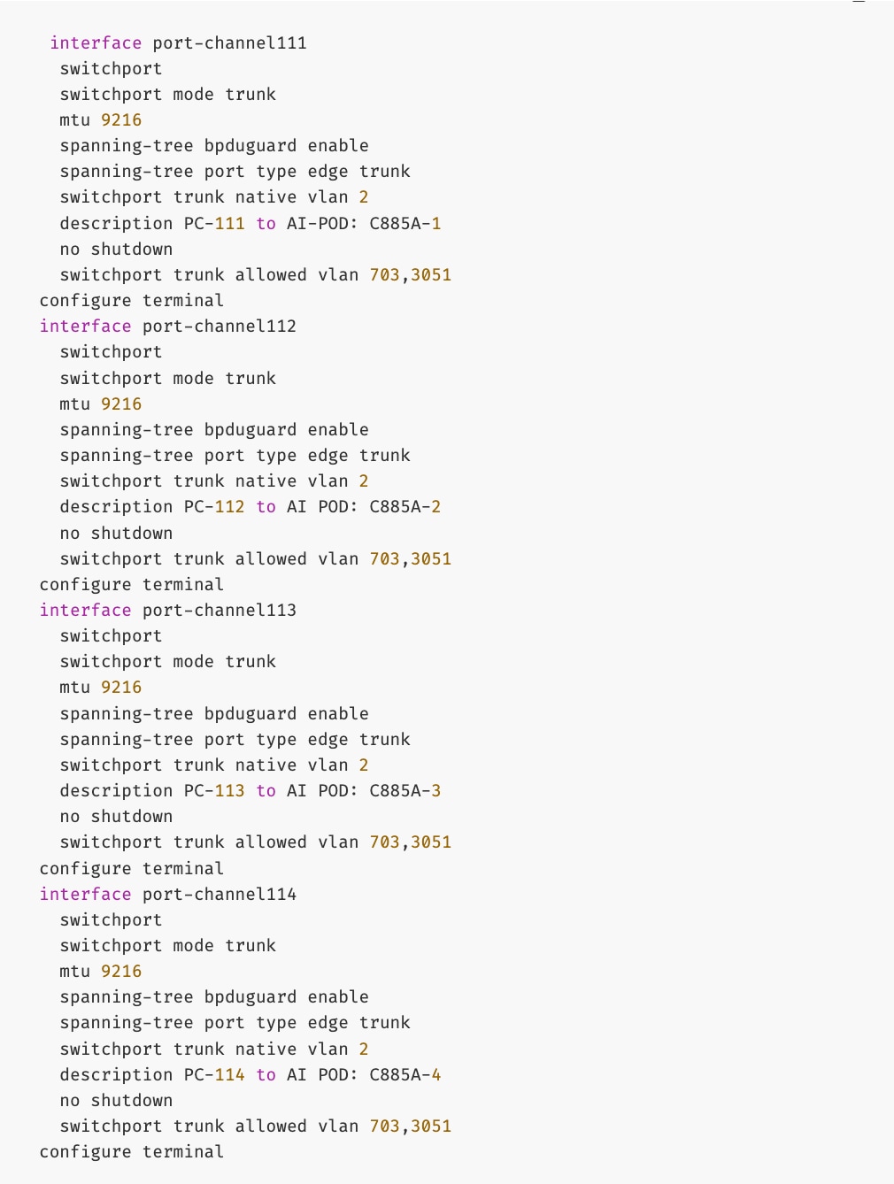
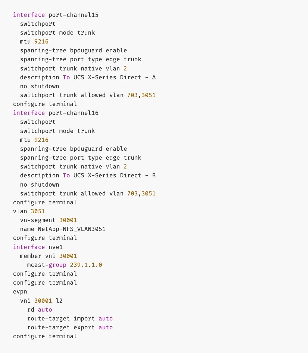
Step 18. Repeat this procedure to deploy the second NFS storage data VLAN.
Procedure 2. Enable NFS Storage Data Access to NetApp Storage using the second NFS VLAN (Optional)
Step 1. Use a web browser to navigate to Nexus Dashboard. Use the management IP of any node in the ND cluster. Log in using admin account.
Step 2. From the left navigation menu, go to Manage > Fabrics.
Step 3. Select the FE fabric and go to Segmentation and Security > Networks tab.
Step 4. Click the lower of the two Actions buttons and select Create from the menu.
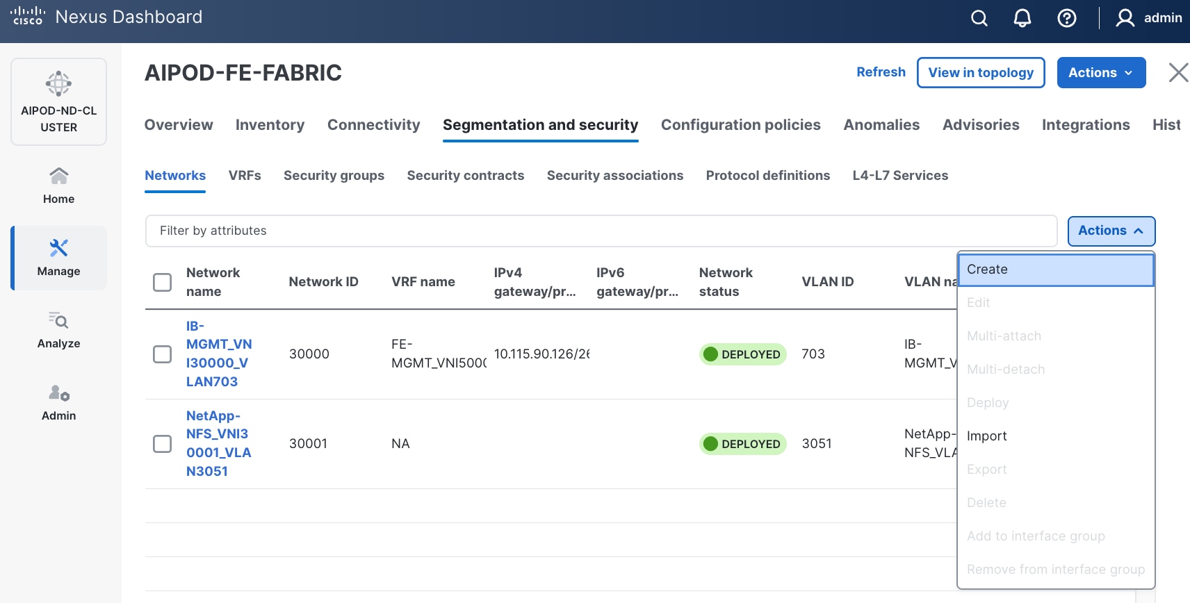
Step 5. In the Create Network window, specify the following:
● Network name
● Enable checkbox for Layer 2 only Layer 2 only.
● Network IDNetwork ID or use default.
● VLAN ID VLAN ID or click Propose VLAN Propose VLAN to let system define a VLAN.
● In the General Parameters tab, specify VLAN Name and Interface Description.
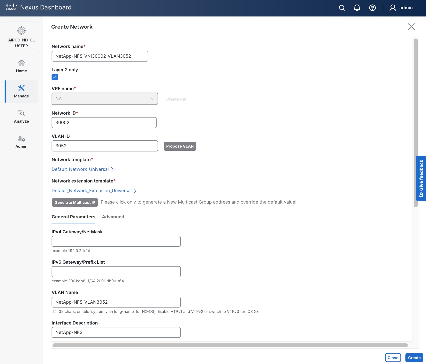
Step 6. Click Create to create the second NFS Storage Data Network.
Step 7. Select the newly created network.
Step 8. Click the lower of the two Actions button and select Multi-attach from the list.
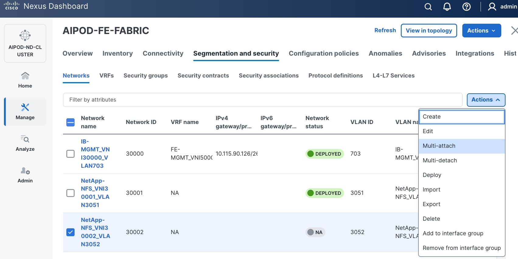
Step 9. Select the compute and storage Leaf switch pairs.
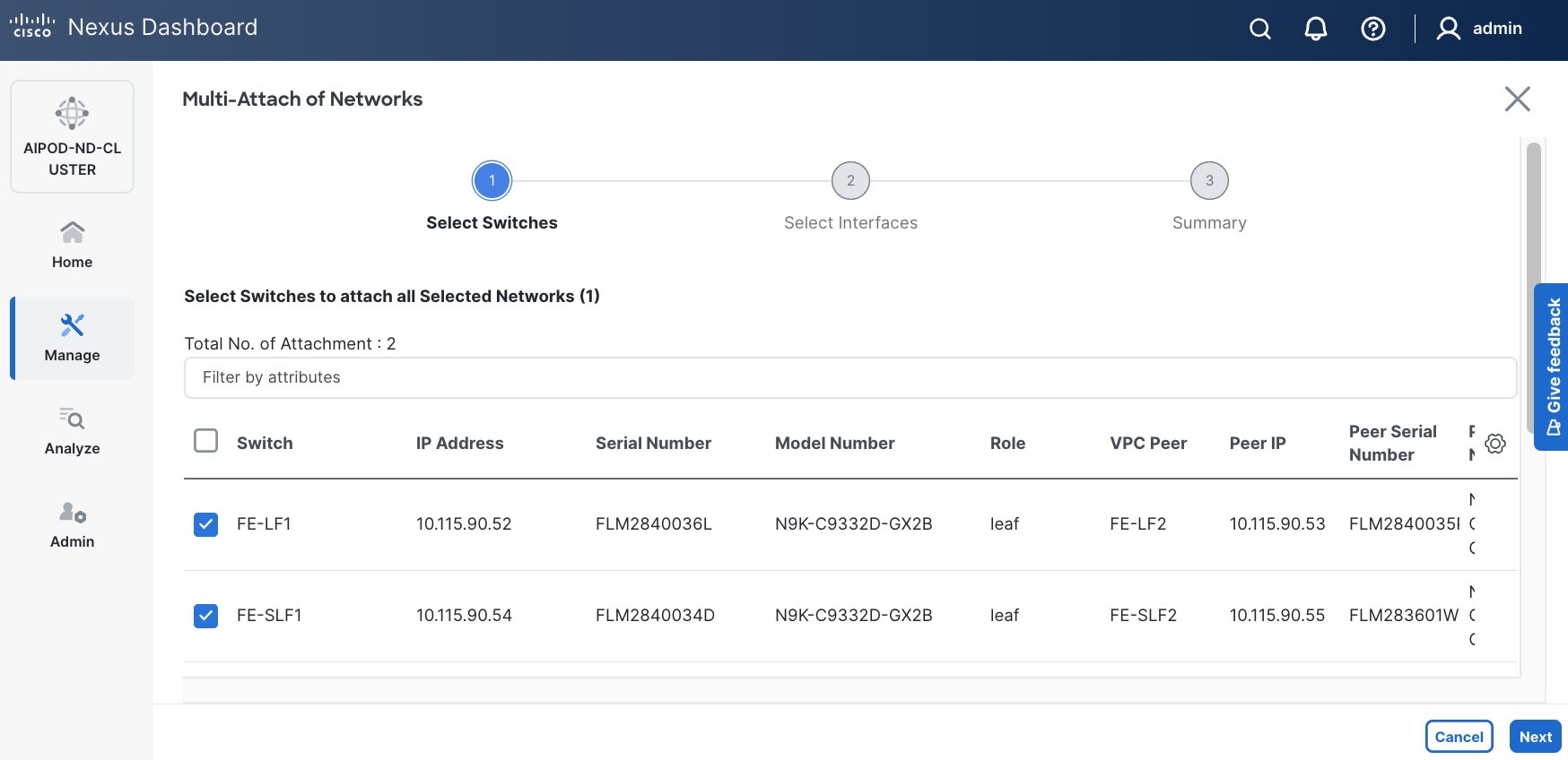
Step 10. Click Next.
Step 11. Select each switch pair in the list and click Select interfaces on the right to deploy this network as a trunked VLAN on the selected interfaces. This should include the ports on the compute and storage leaf pair that connect to UCS nodes and NetApp storage, respectively. Additional interfaces can be added later as needed.
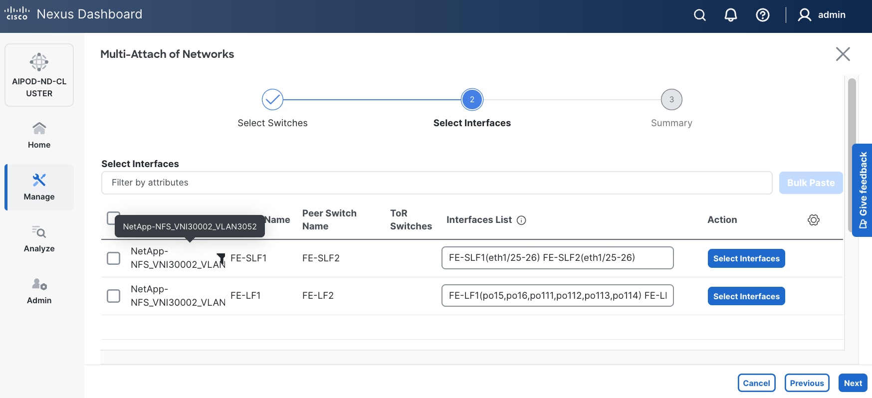
Step 12. Click Next.
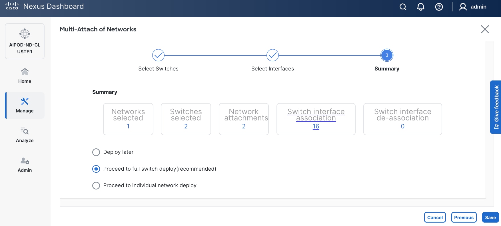
Step 13. Click Save.
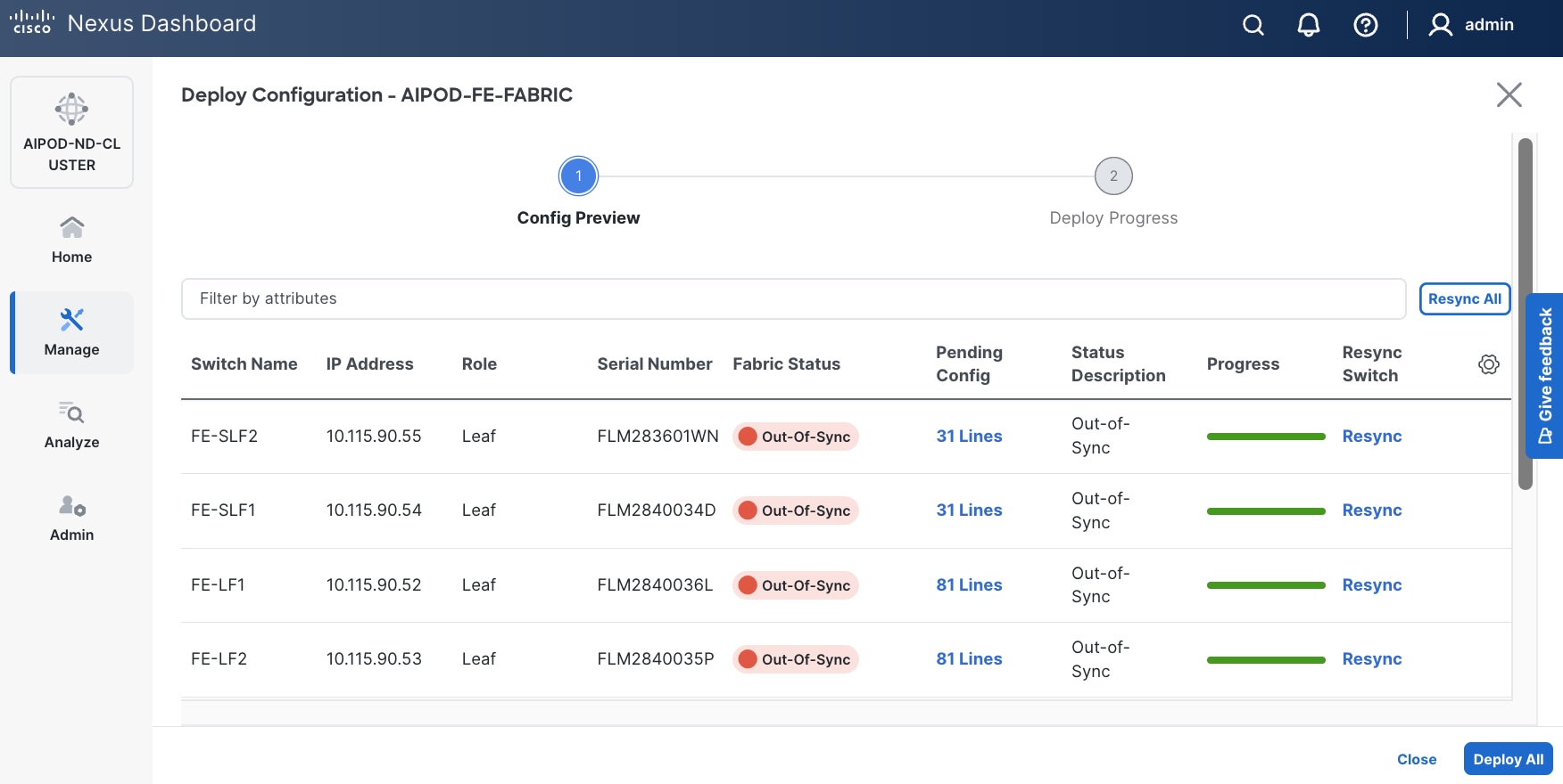
Step 14. Click Pending Config to see the configuration being deployed. The pending configuration on one leaf switch is provided as a reference at the end.
Step 15. Click Deploy All.
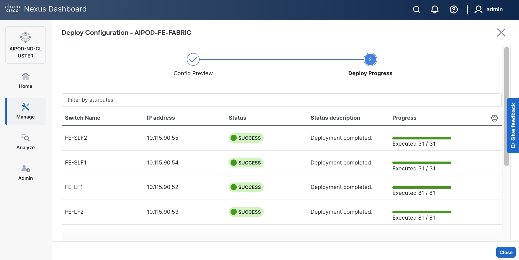
Step 16. Click Close.
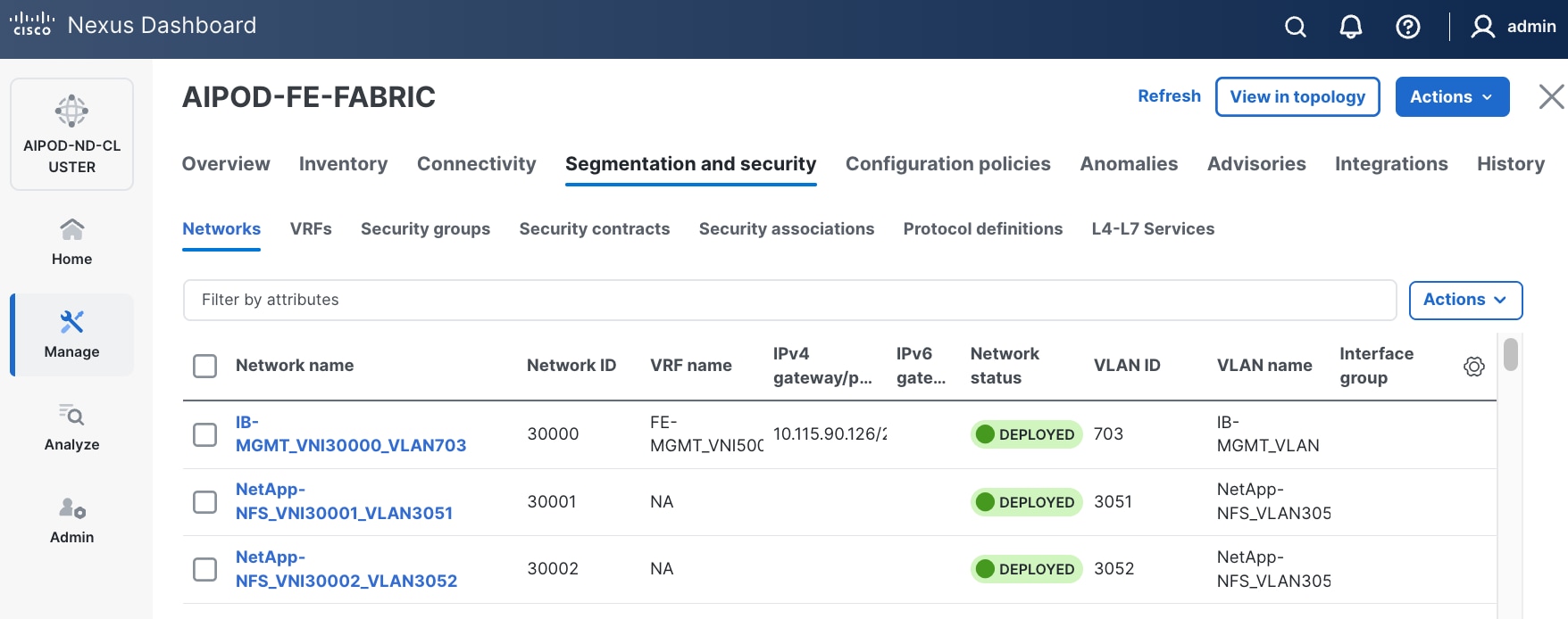
Step 17. Click the Network name to verify that the network was successfully deployed on the relevant switches and interfaces.
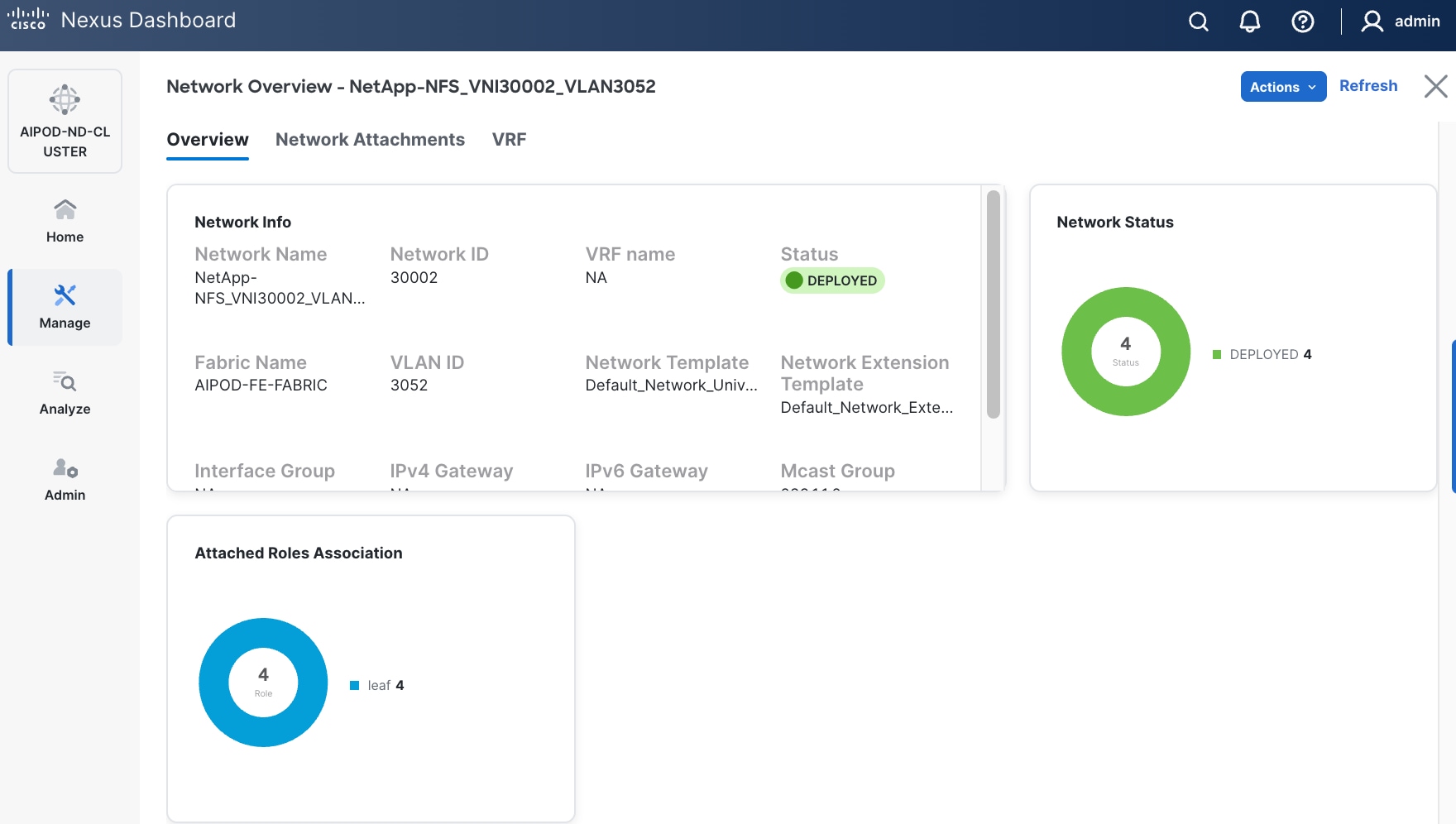
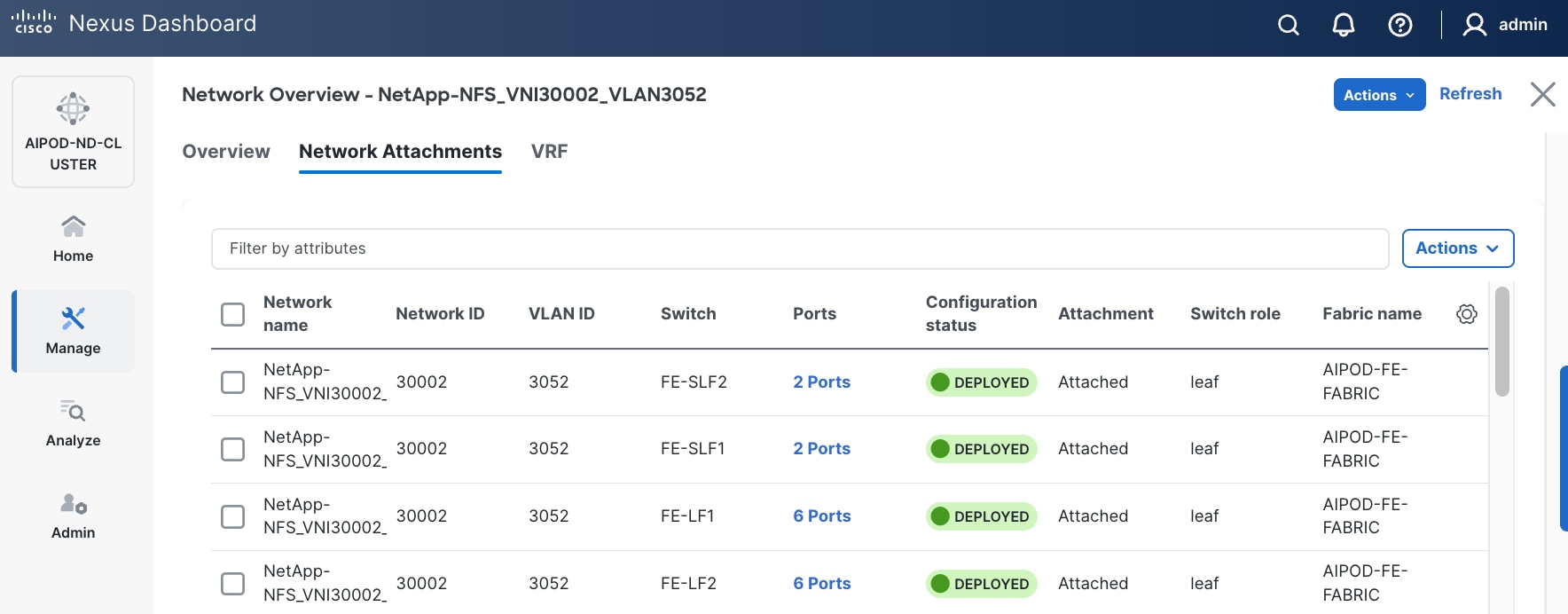
Step 18. The configuration deployed on one compute leaf switch is provided below as a reference:
● StorageStorage Leaf
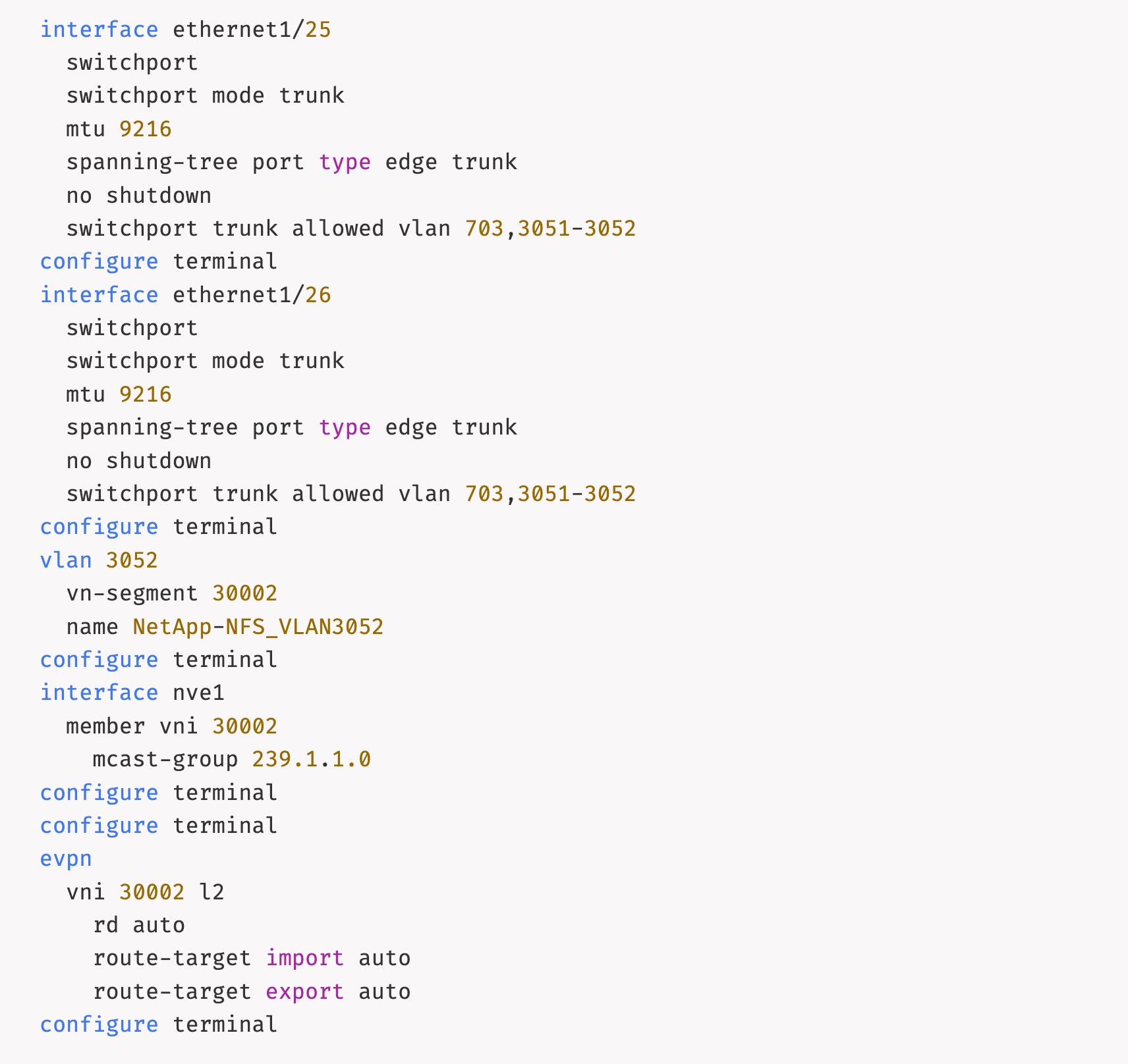
● ComputeCompute Leaf
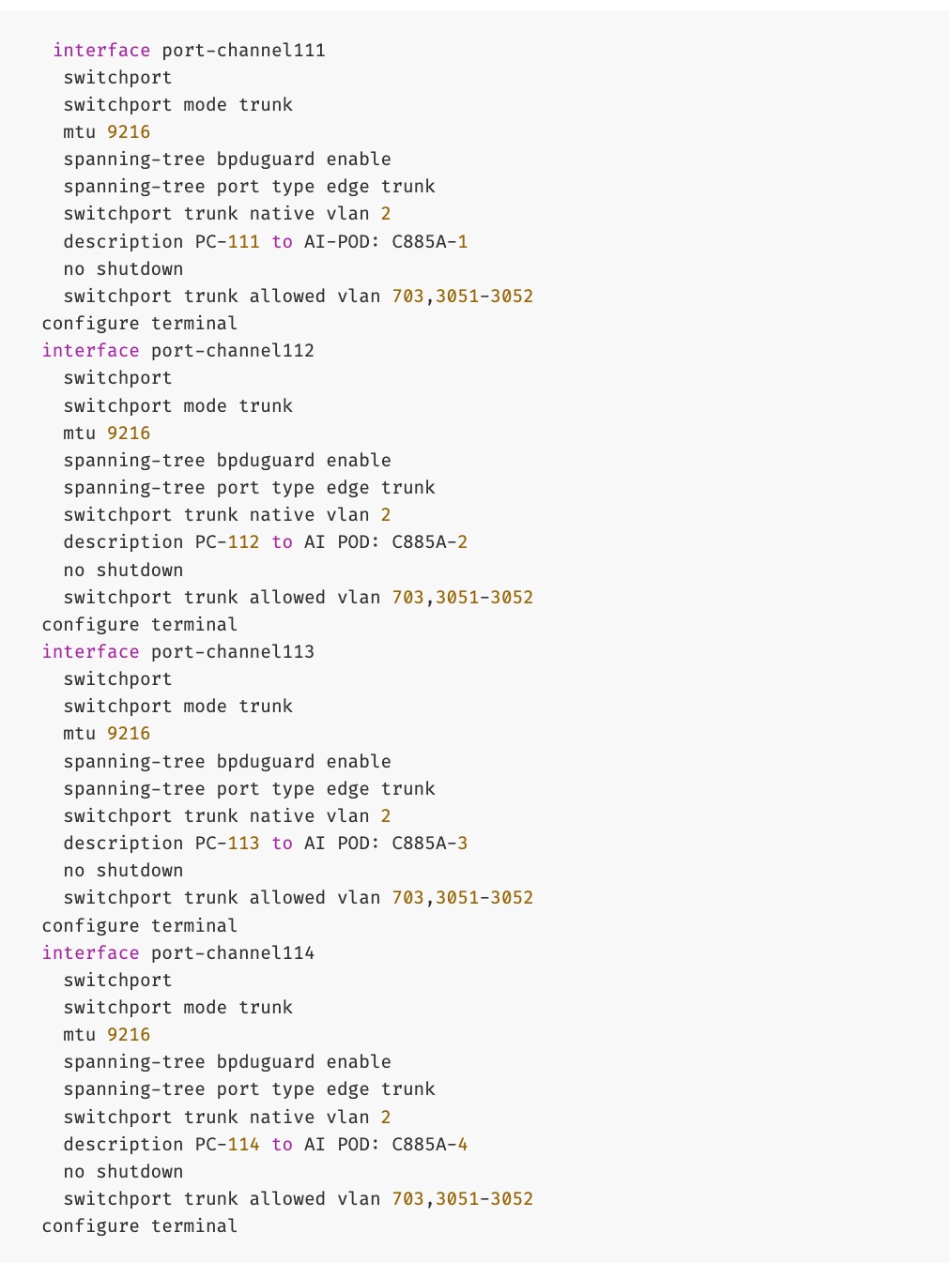
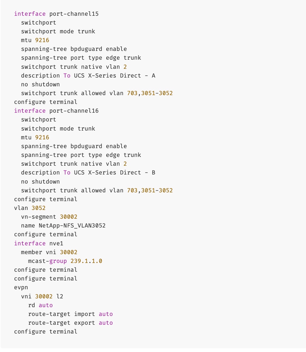
(Ubuntu) Enable NFS Storage Data Access to BCM Node(s)
To enable NFS storage data access to BCM nodes, you will be deploying this network on the storage Leaf switch pair that connects to the BCM node.
Table 17. Setup Parameters for FE Fabric: NFS Storage Data Access Connectivity to BCM Node(s)
| Parameter Type |
Parameter Name | Value |
Parameter Type |
| IB-MGMT Network |
|
|
| Name |
NetApp-NFS_VN30001_VLAN3051 |
|
| BCM Node |
|
|
| vPC Leaf Switch Pair |
FE-SLF1, FE-SLF2 |
|
| BCM Interface |
Port-Channel 18 |
|
To enable NFS storage data access to BCM node(s), follow the procedures below.
Procedure 1. Enable NFS storage data access to BCME Node
Step 1. Use a web browser to navigate to Nexus Dashboard. Use the management IP of any node in the ND cluster. Log in using admin account.
Step 2. From the left navigation menu, go to Manage > Fabrics.
Step 3. Select the FE fabric and go to Segmentation and Security > Networks tab.
Step 4. Select the previously deployed NFS storage data access network from the list.
Step 5. Click the lower of the two Actions buttons and select Multi-attach from the menu.
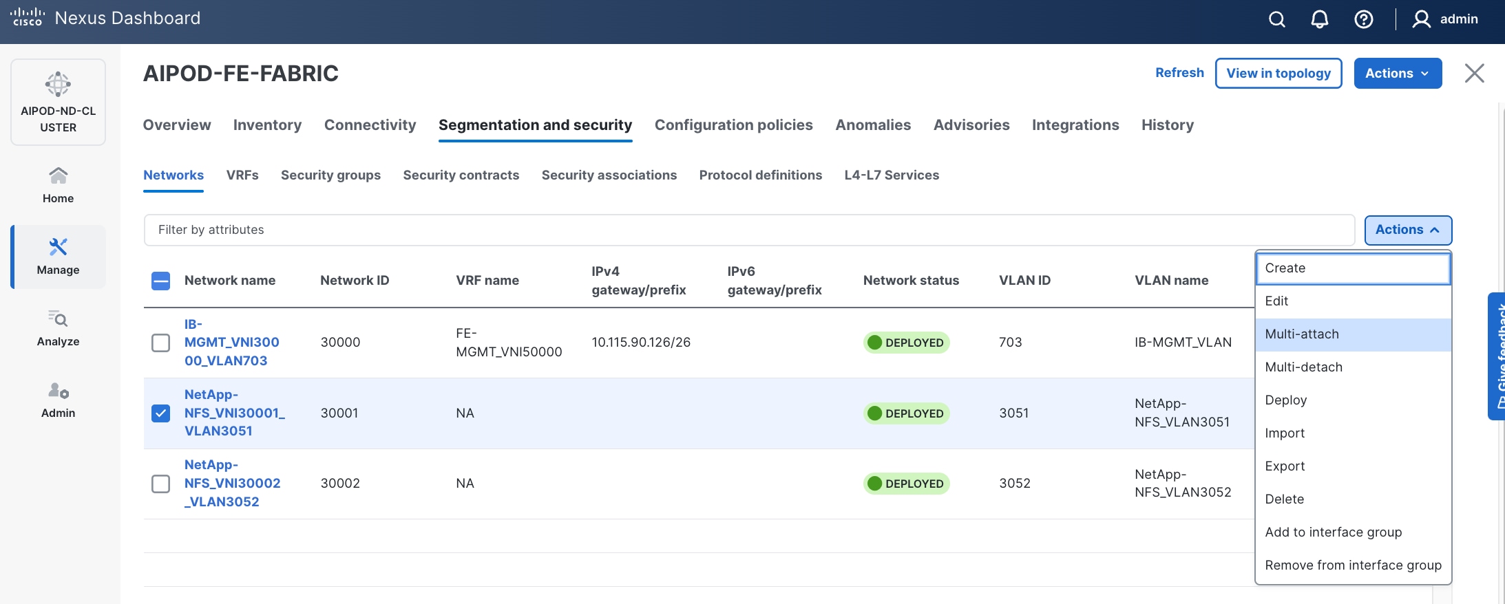
Step 6. Select the leaf switch pair from the list that the BCM node connects.
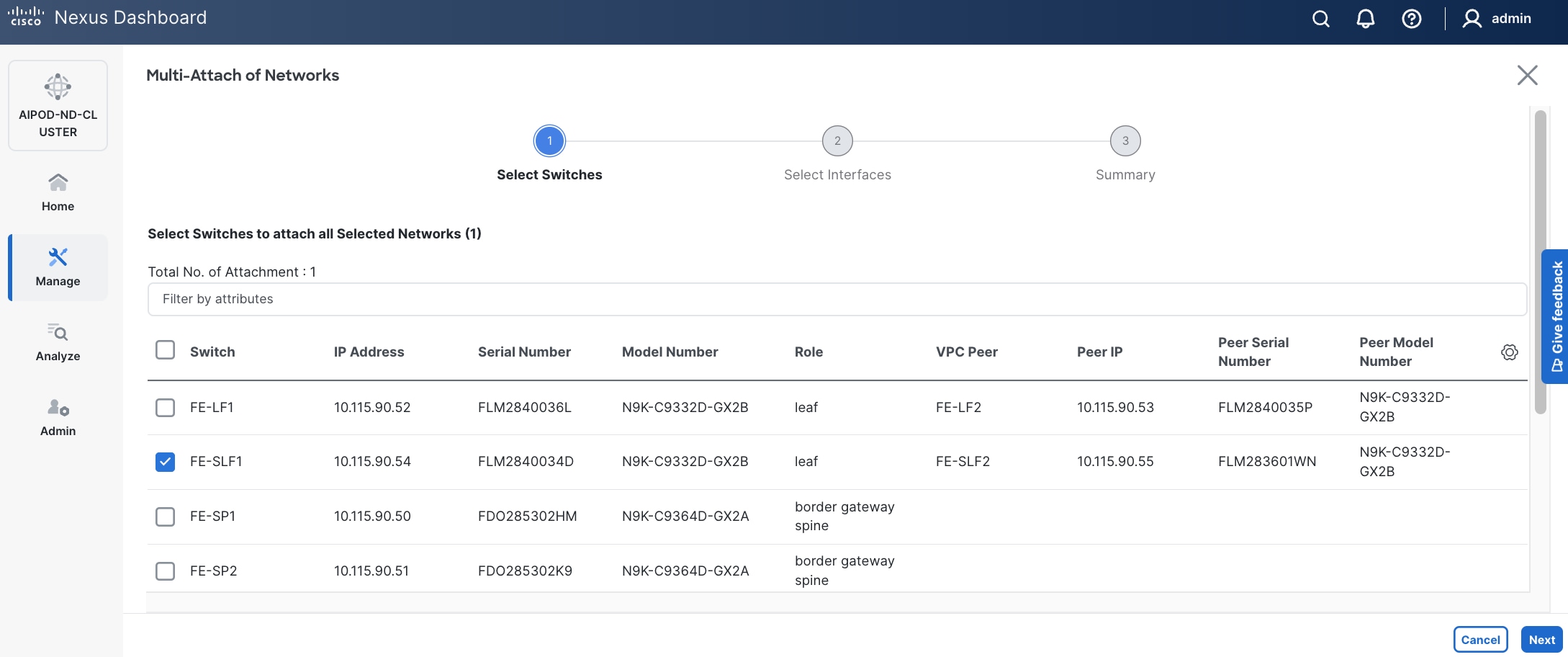
Step 7. Click Next.
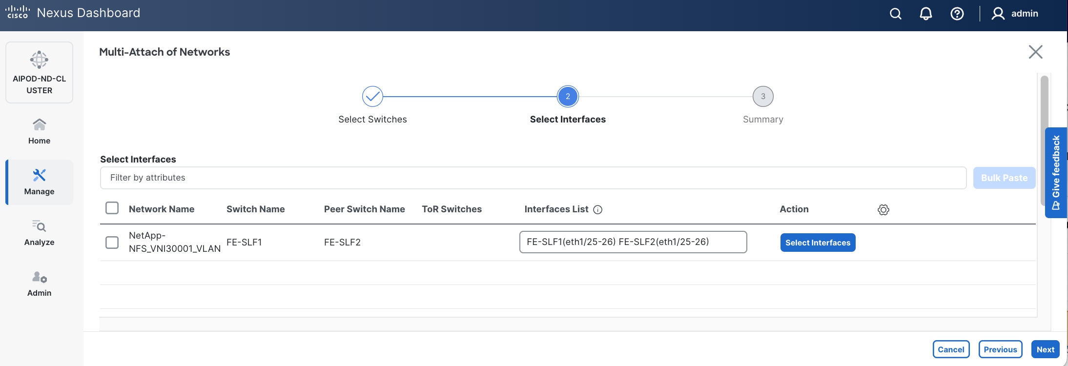
Step 8. Click Select Interfaces to the right of the network to add the interfaces that connect to the BCME node. Select the port channel on both leaf switches in the leaf pair.
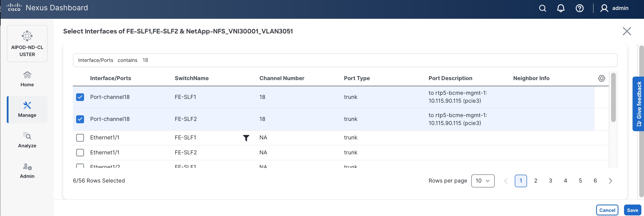
Step 9. Click Save.
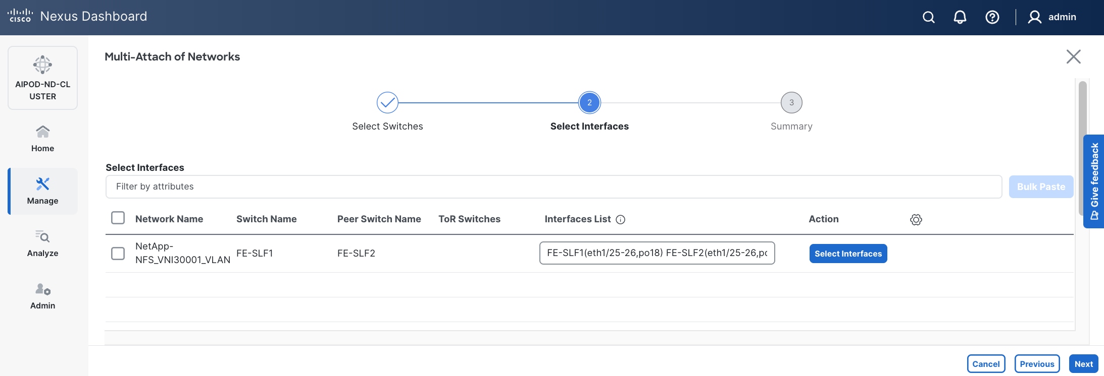
Step 10. Click Next.
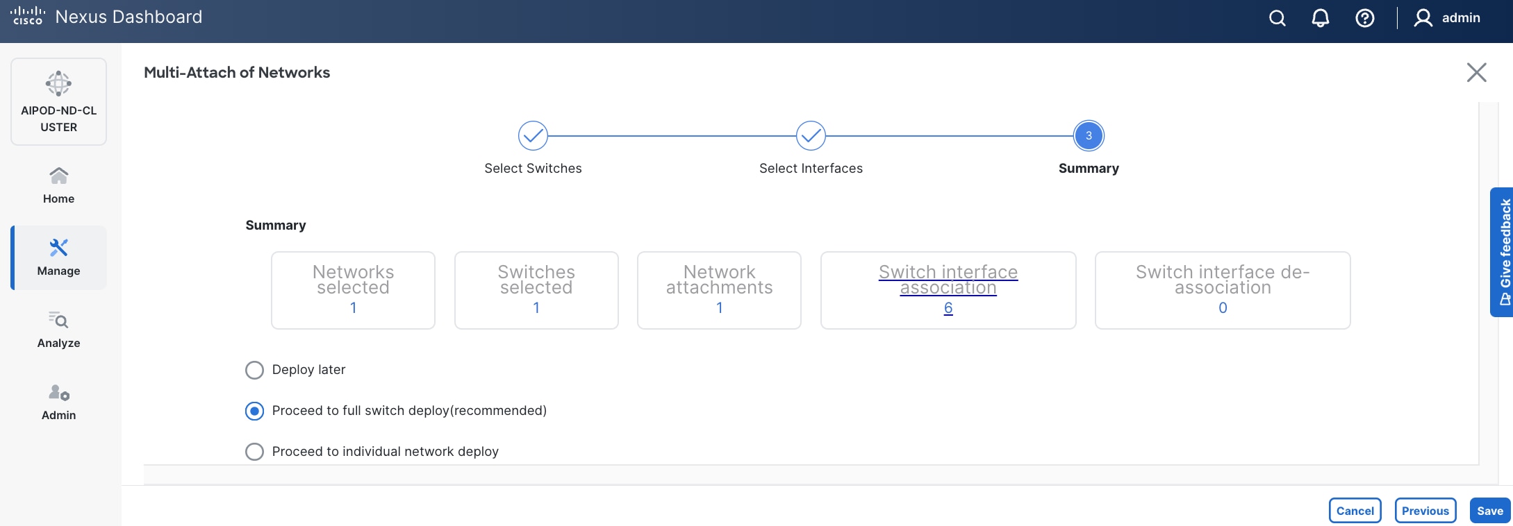
Step 11. Click Save.
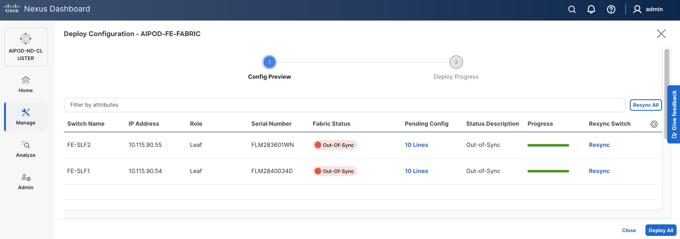
The configuration deployed on one storage leaf switch is provided below as a reference:
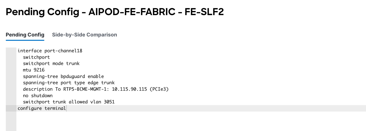
Step 12. Click Deploy All.
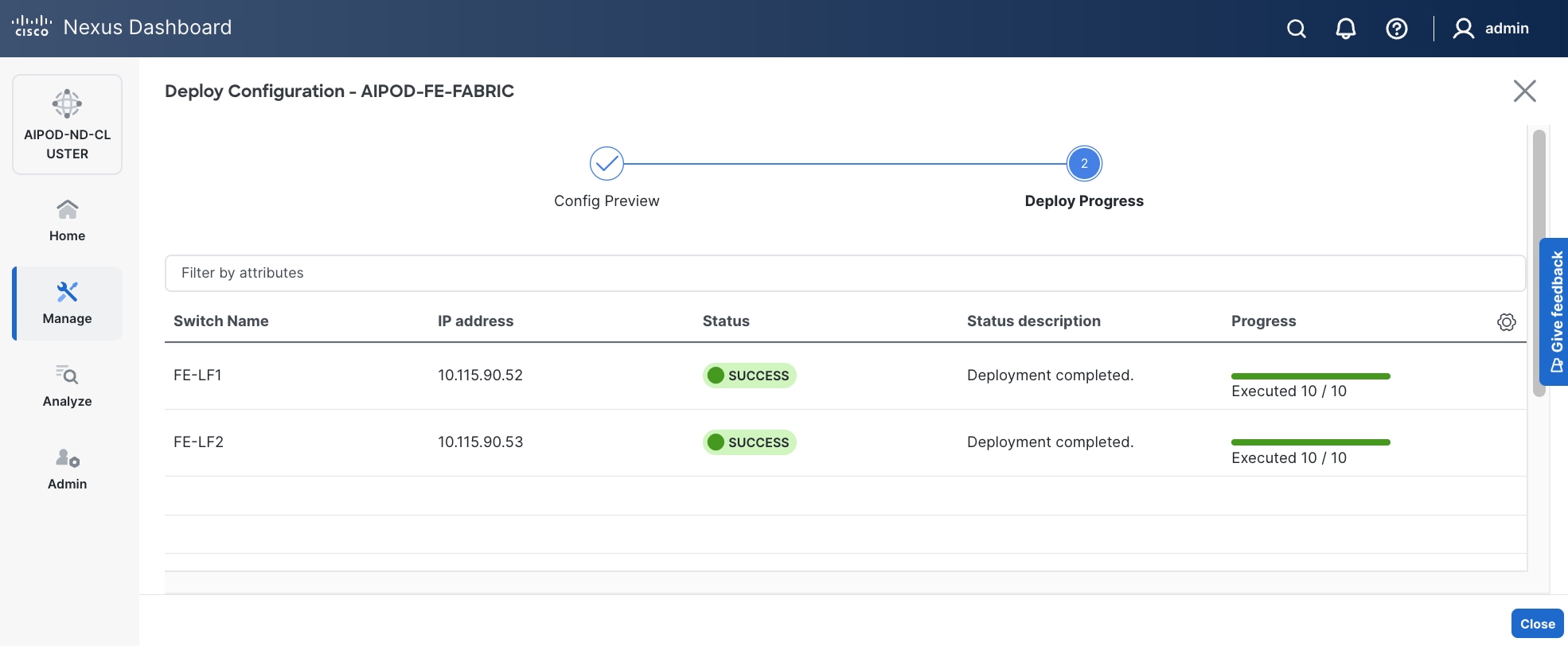
Step 13. Click Close.
Step 14. Click the Network name to verify that the network was successfully deployed on the relevant switches and interfaces.
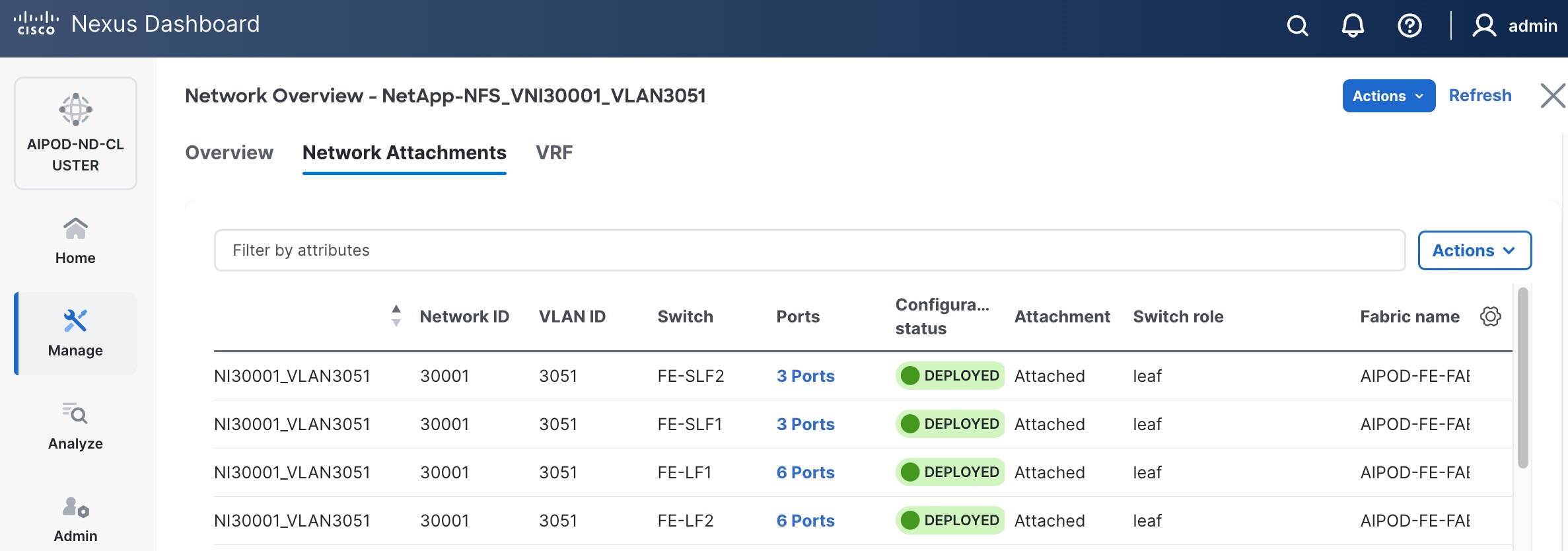
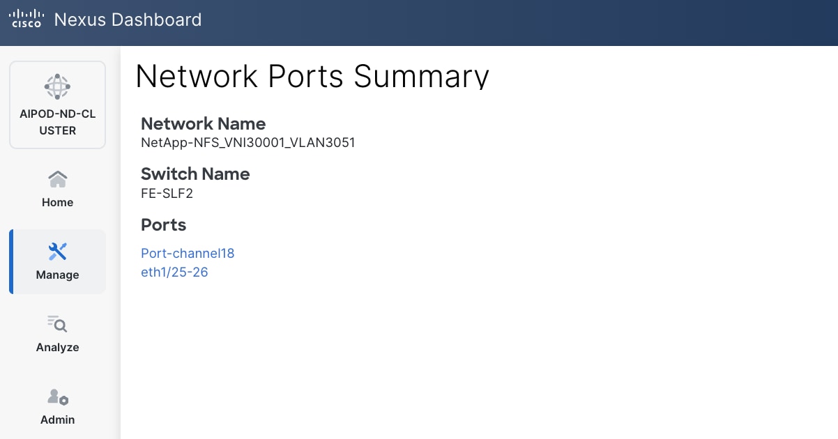
Enable QoS for FE Fabric
Table 18. Setup Parameters for FE Fabric: QoS
| Parameter Type |
Parameter Name | Value |
Parameter Type |
| Modified QoS Policy |
|
|
| Name |
AIPOD-FE-QOS-200G |
|
| Priority Flow Control (PFC) MTU |
9216 |
Default = 4200 |
| Fabric Settings |
|
|
| AI QoS and Queueing Policies |
Enable |
Checkbox |
| AI QoS and Queueing Policy |
AIPOD-FE-QOS-200G |
Select modified policy from drop-down list |
| Interface Settings |
|
|
| Priority Flow Control |
Enable |
Checkbox |
| QoS |
Enable |
Checkbox |
To deploy QoS on the frontend fabric, follow the procedure below.
Procedure 1. Modify default QoS policy for FE fabric
Step 1. Use a web browser to navigate to Nexus Dashboard. Use the management IP of any node in the ND cluster. Log in using admin account.
Step 2. From the left navigation menu, go to Manage > Template Library.
Step 3. Use Filter to view all templates that contain QOS in the name.
Step 4. Select the AI_Fabric_QoS_100G policy.
Step 5. Click the lower of the two Actions buttons and select Duplicate template from the menu.
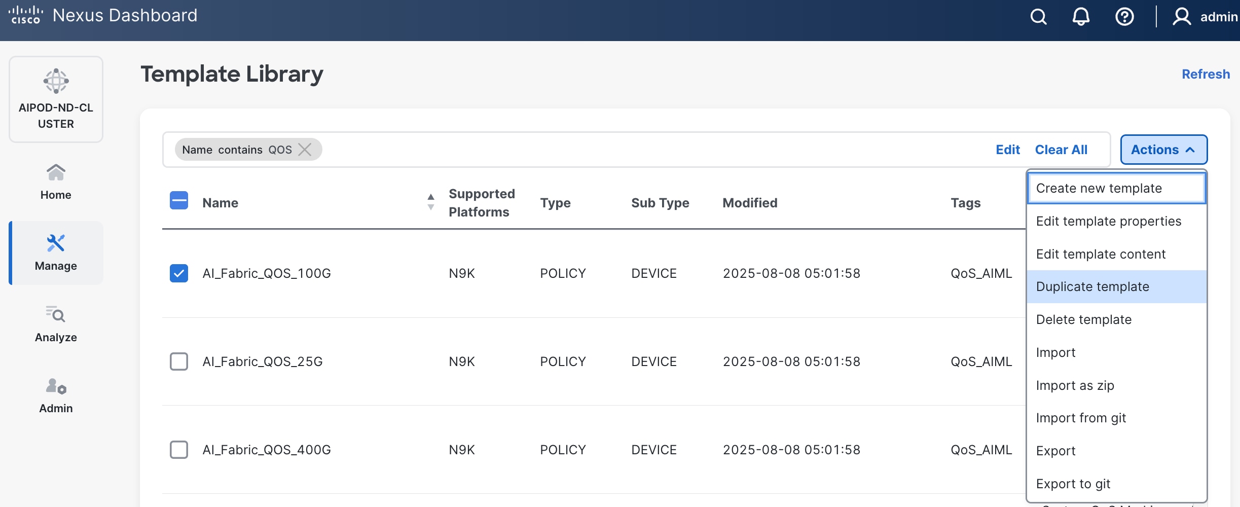
Step 6. For Template Properties, specify a Template Name for the new template. Adjust the Description as needed.
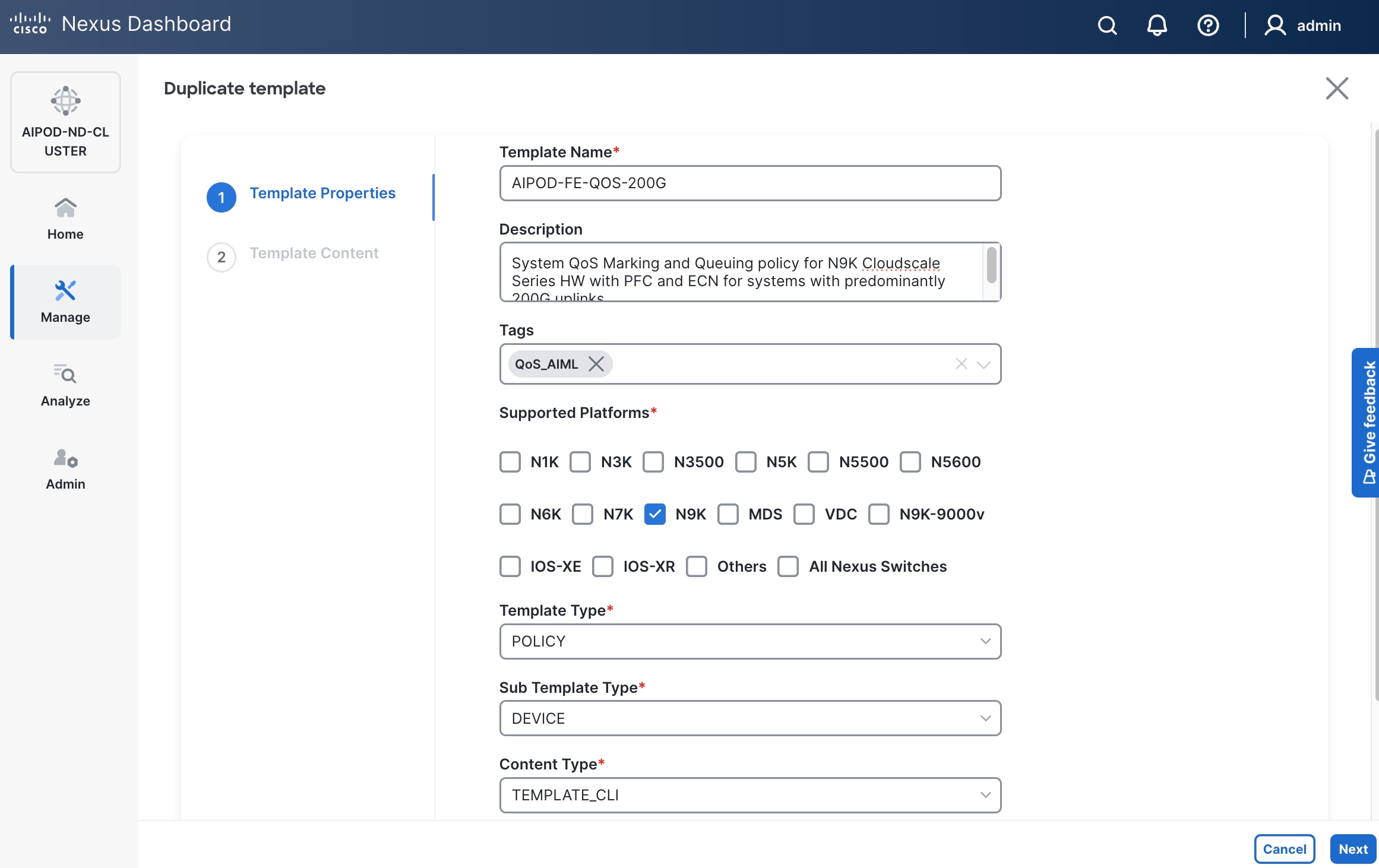
Step 7. Click Next.
Step 8. For Template Content, scroll down to policy-map type network-qos qos_network, and change the MTU for PFC from 4200 to default of 9216 as shown.
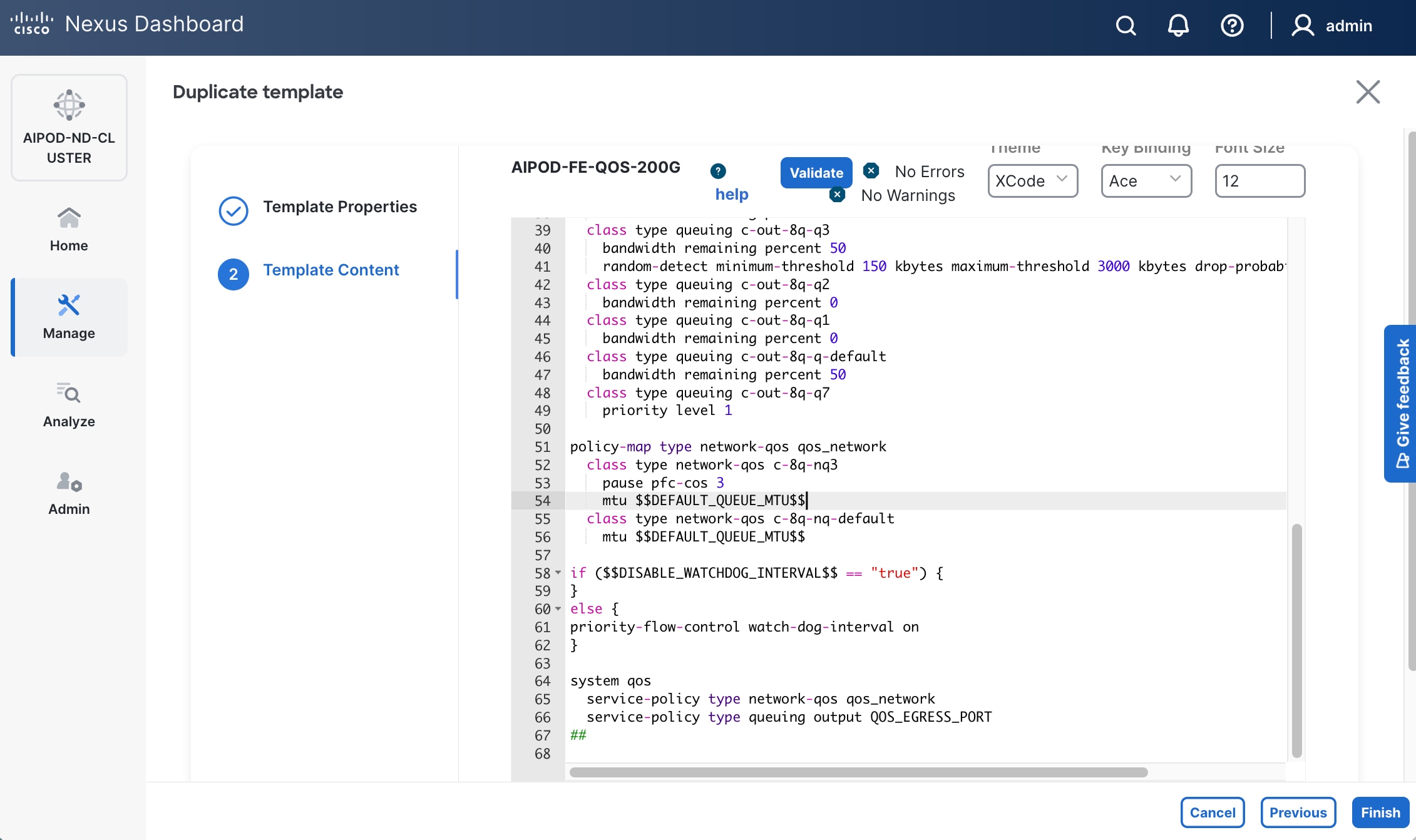
Step 9. Click Finish.
Procedure 2. Deploy modified QoS policy in Frontend Fabric
Step 1. Use a web browser to navigate to Nexus Dashboard. Use the management IP of any node in the ND cluster. Log in using admin account.
Step 2. From the left navigation menu, go to Manage > Fabrics.
Step 3. Select the FE fabric.
Step 4. Click the higher of the two Actions buttons and select Edit fabric settings.
Step 5. Go to Fabric management > Advanced.
Step 6. Scroll down and enable the checkbox for Enable AI QoS and Queuing Policies.
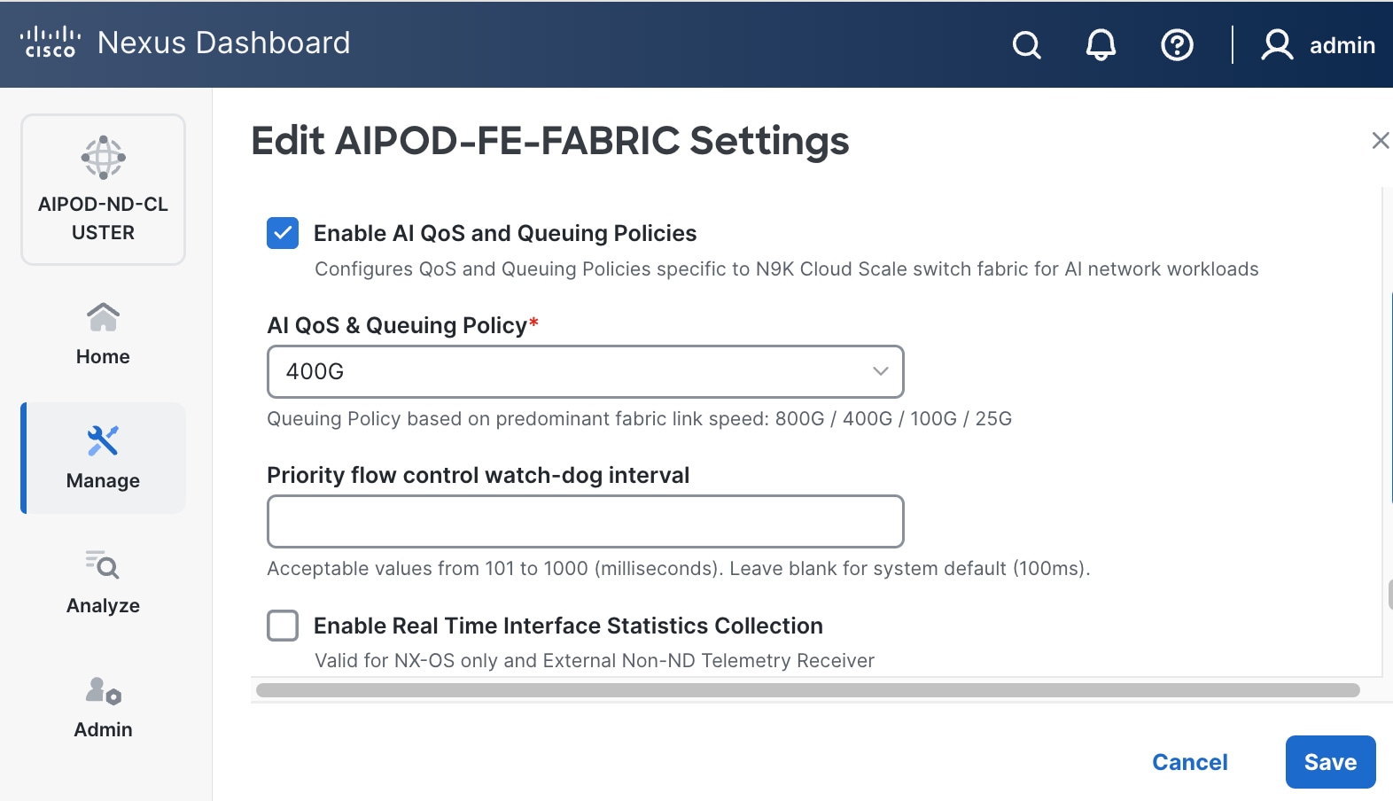
Step 7. For AI QoS & Queuing Policy, select the modified QoS policy from the drop-down list.
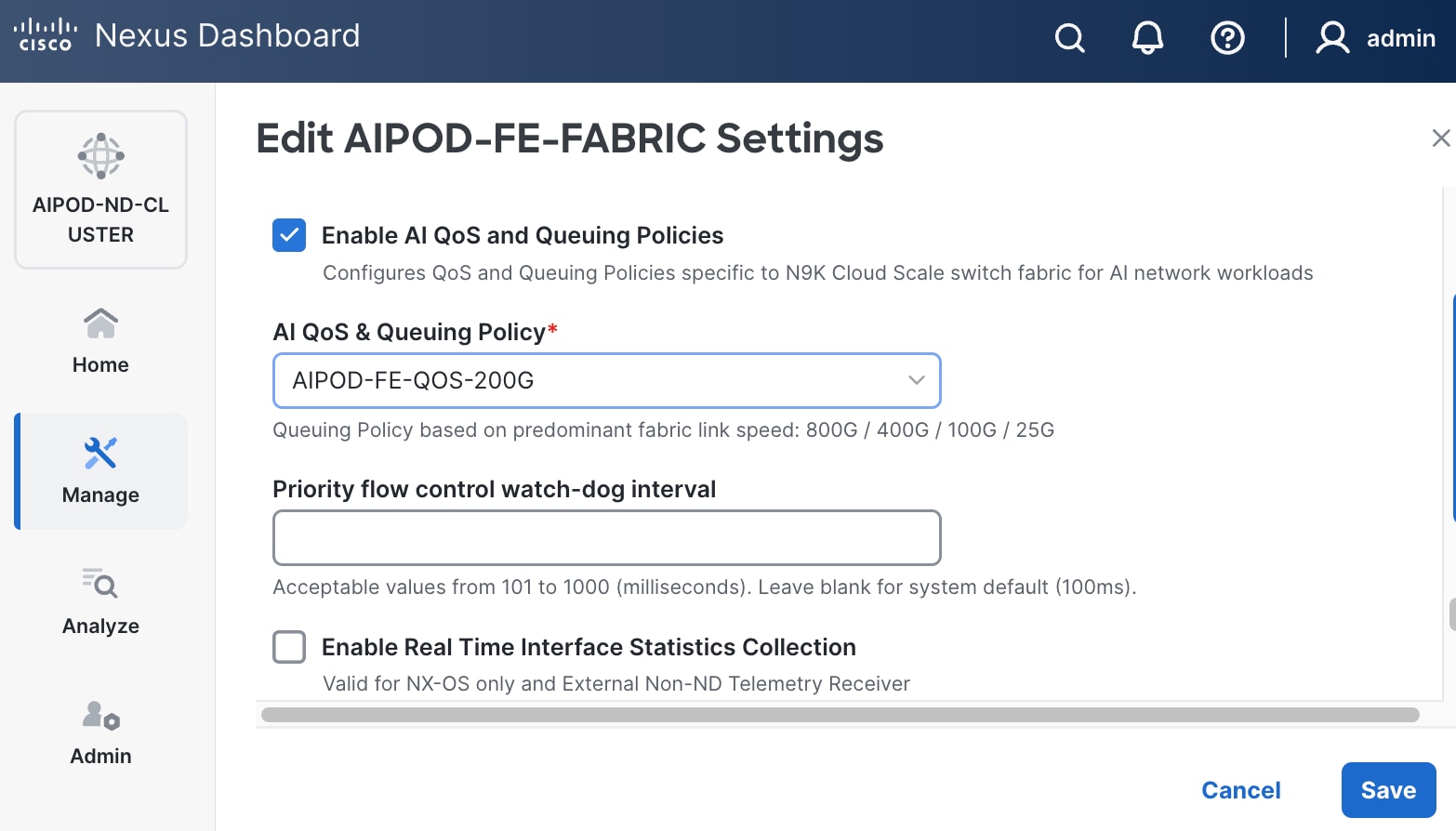
Step 8. Click Save.
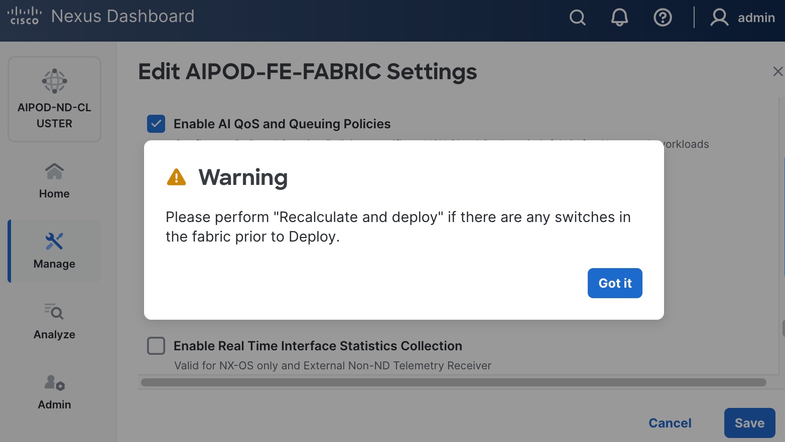
Step 9. In the pop-up window, review warning and click Got It.
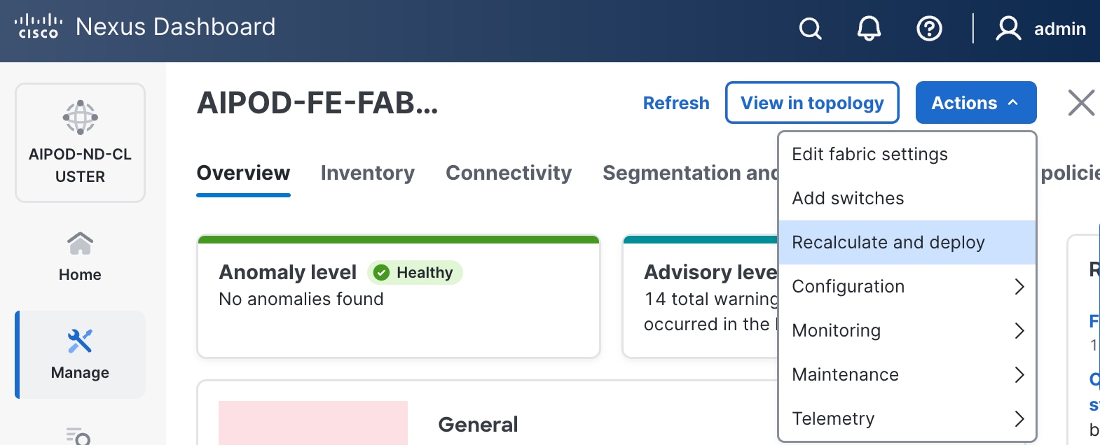
Step 10. Click the higher of the two Actions buttons and select Recalculate and deploy from the menu.
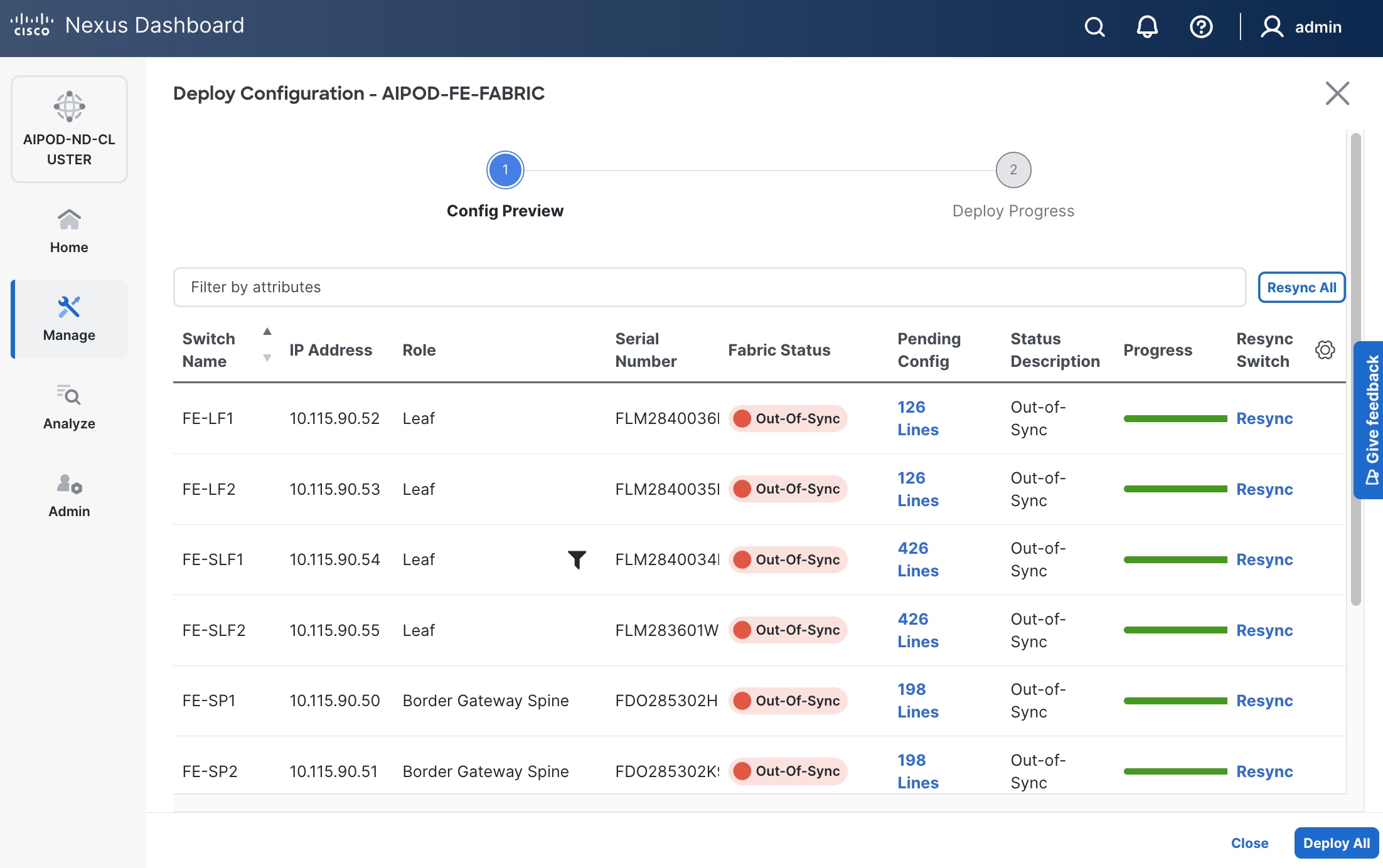
Step 11. Click Deploy All.
Step 12. Click Close.
Procedure 3. Enable Priority Flow Control on interfaces
Step 1. Use a web browser to navigate to Nexus Dashboard. Use the management IP of any node in the ND cluster. Log in using admin account.
Step 2. From the left navigation menu, go to Manage > Fabrics.
Step 3. Select the FE fabric and go to Connectivity > Interfaces.
Step 4. Select the first interface and click the lower of the two Actions buttons and select Edit interface.
Step 5. Scroll down to the bottom and enable the following two QoS related settings.
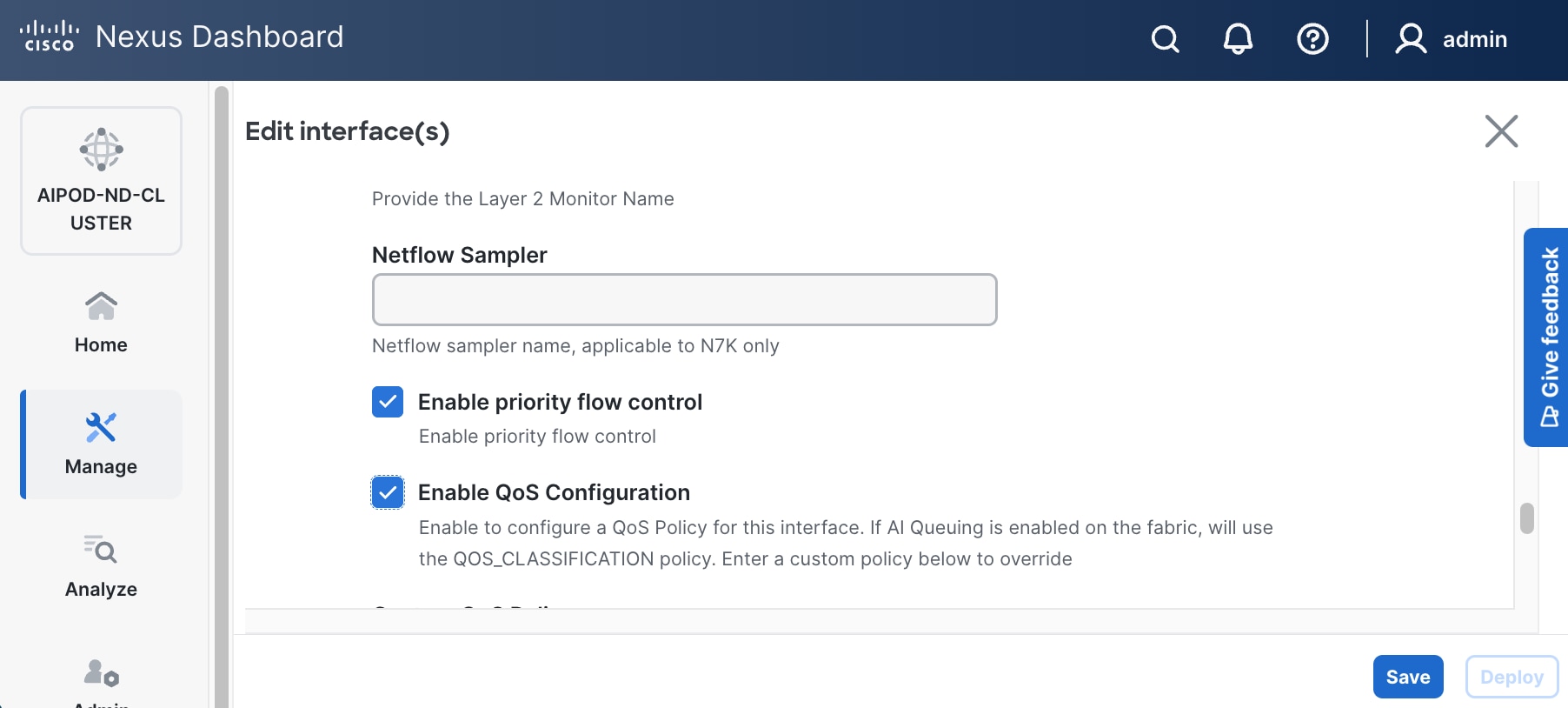
Step 6. Click Save.
Step 7. Click Deploy.
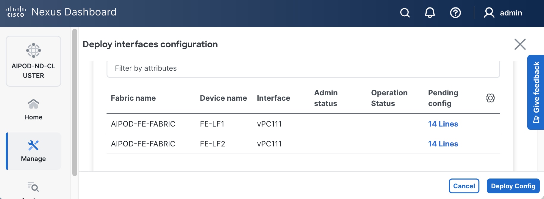
Step 8. Click Pending config to see configuration that will be deployed on the interface on each switch.
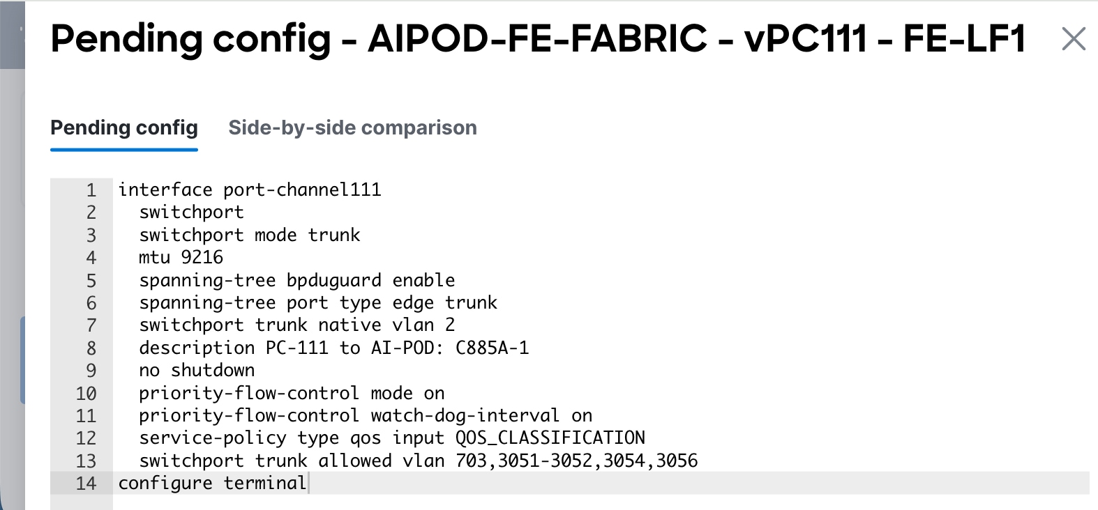
Step 9. Click Deploy Config.
Step 10. Repeat this procedure for all remaining interfaces on both leaf switches that access the storage system.
In this setup, the Nexus Backend Fabric consisted of 2 spine and 2 leaf switches. This fabric was cabled according to Table 4. The fabric switch details are listed in Table 19.
Table 19. Backend Fabric Switch Details
| Switch |
Role |
OOB IP |
Firmware |
Model |
| BE-LF1 |
Leaf |
10.115.90.58 |
10.4(5) |
Cisco Nexus 9332D-GX2B |
| BE-LF2 |
Leaf |
10.115.90.59 |
10.4(5) |
Cisco Nexus 9332D-GX2B |
| BE-SP1 |
Spine |
10.115.90.60 |
10.4(5) |
Cisco Nexus 9364D-GX2A |
| BE-SP2 |
Spine |
10.115.90.61 |
10.4(5) |
Cisco Nexus 9364D-GX2A |
Physical Connectivity
Follow the physical connectivity guidelines for FlexPod as explained in section FlexPod Cabling.
Initial Configuration of Switches
The following procedures describe this basic configuration of the Cisco Nexus backend fabric switches for use in the FlexPod environment. This procedure assumes the use of Cisco Nexus 9000 10.4(5), the Cisco suggested Nexus switch release at the time of this validation.
Procedure 4. Set Up Initial Configuration from a serial console
Step 1. Set up the initial configuration for each backend fabric switch as listed in Table 7.
Step 2. Configure the switch.
Note: On initial boot, the NX-OS setup automatically starts and attempts to enter Power on Auto Provisioning.
Abort Power On Auto Provisioning [yes - continue with normal setup, skip - bypass password and basic configuration, no - continue with Power On Auto Provisioning] (yes/skip/no)[no]: yes
Disabling POAP.......Disabling POAP
poap: Rolling back, please wait... (This may take 5-15 minutes)
---- System Admin Account Setup ----
Do you want to enforce secure password standard (yes/no) [y]: Enter
Enter the password for "admin": <password>
Confirm the password for "admin": <password>
Would you like to enter the basic configuration dialog (yes/no): yes
Create another login account (yes/no) [n]: Enter
Configure read-only SNMP community string (yes/no) [n]: Enter
Configure read-write SNMP community string (yes/no) [n]: Enter
Enter the switch name: <nexus-hostname>
Continue with Out-of-band (mgmt0) management configuration? (yes/no) [y]: Enter
Mgmt0 IPv4 address: <nexus-out_of_band_mgmt0-ip>
Mgmt0 IPv4 netmask: <nexus-mgmt0-netmask>
Configure the default gateway? (yes/no) [y]: Enter
IPv4 address of the default gateway: <nexus-mgmt0-gw>
Configure advanced IP options? (yes/no) [n]: Enter
Enable the telnet service? (yes/no) [n]: Enter
Enable the ssh service? (yes/no) [y]: Enter
Type of ssh key you would like to generate (dsa/rsa) [rsa]: Enter
Number of rsa key bits <1024-2048> [2048]: Enter
Configure the ntp server? (yes/no) [n]: Enter
Configure default interface layer (L3/L2) [L2]: Enter
Configure default switchport interface state (shut/noshut) [noshut]: Enter
Enter basic FC configurations (yes/no) [n]: n
Configure CoPP system profile (strict/moderate/lenient/dense) [strict]: Enter
Would you like to edit the configuration? (yes/no) [n]: Enter
Step 3. Review the configuration summary before enabling the configuration.
Use this configuration and save it? (yes/no) [y]: Enter
Step 4. Repeat this configuration for all switches in Table 7.
Deploy Backend Fabric Using Nexus Dashboard
Procedure 1. Deploy BE Cluster
Step 1. Use a web browser to navigate to Nexus Dashboard. Use the management IP of any node in the ND cluster. Log in using admin account.
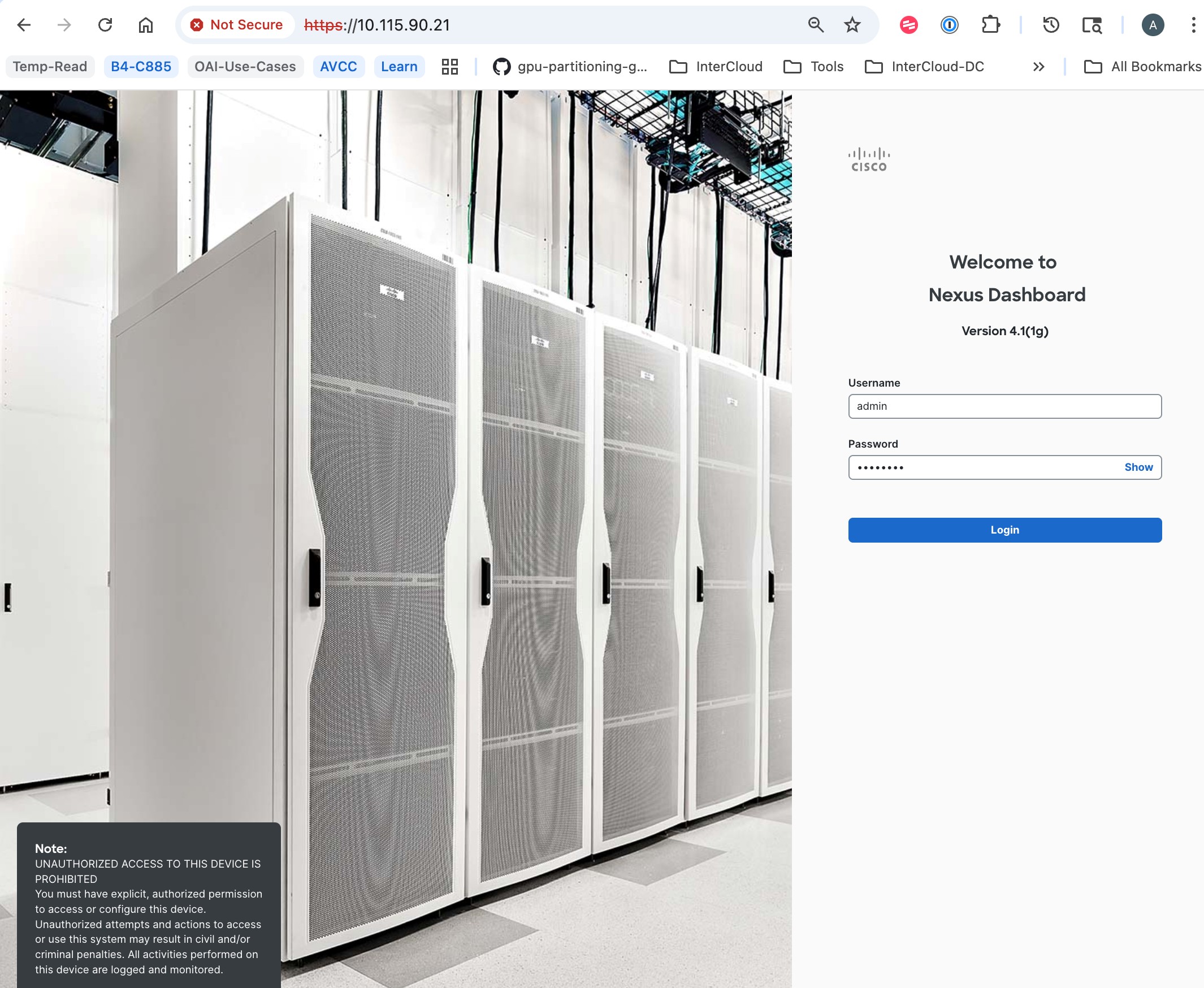
Step 2. Go to Manage > Fabrics.
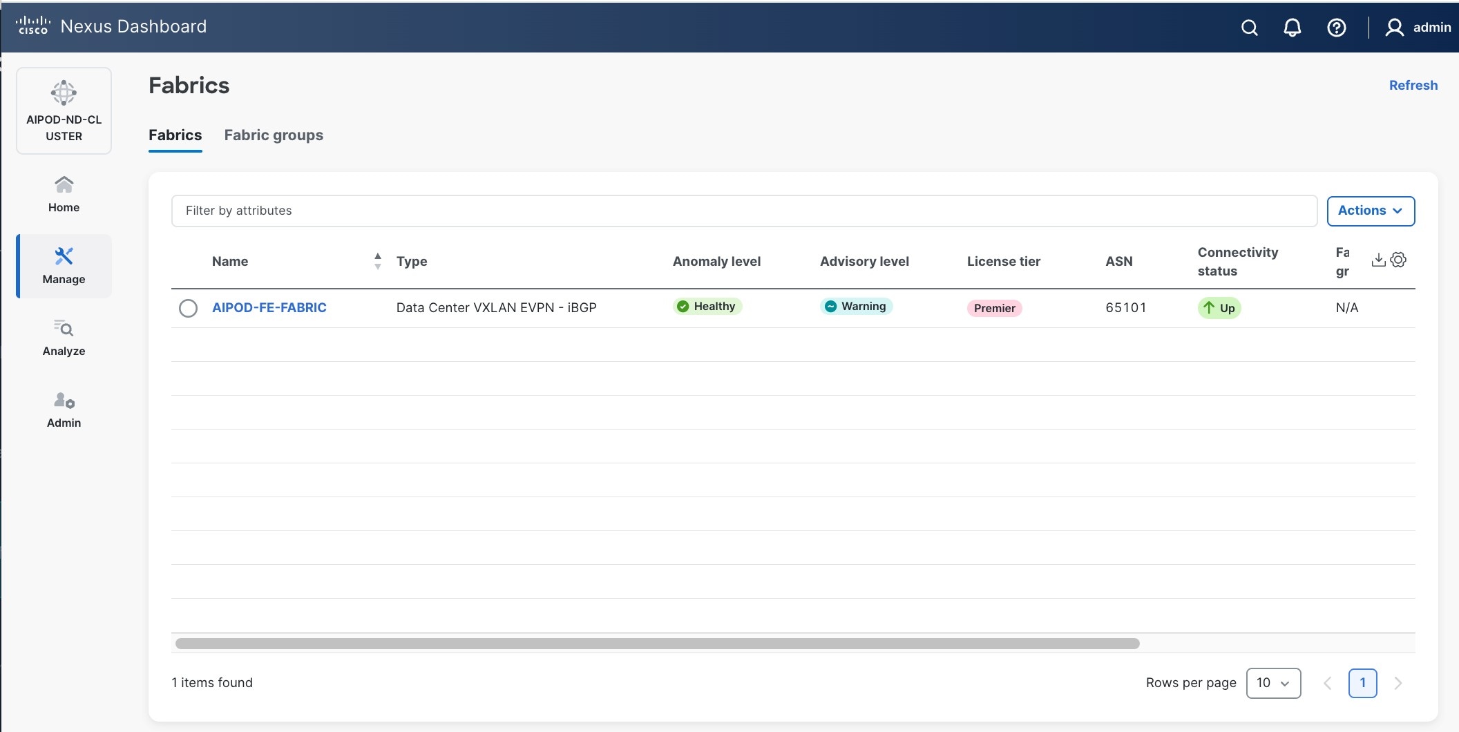
Step 3. Click Actions.
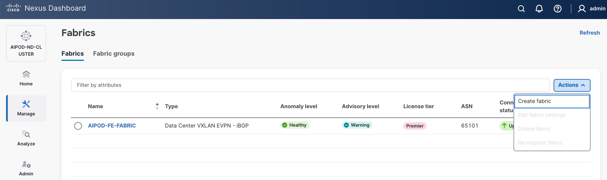
Step 4. Select Create Fabric from the drop-down list.
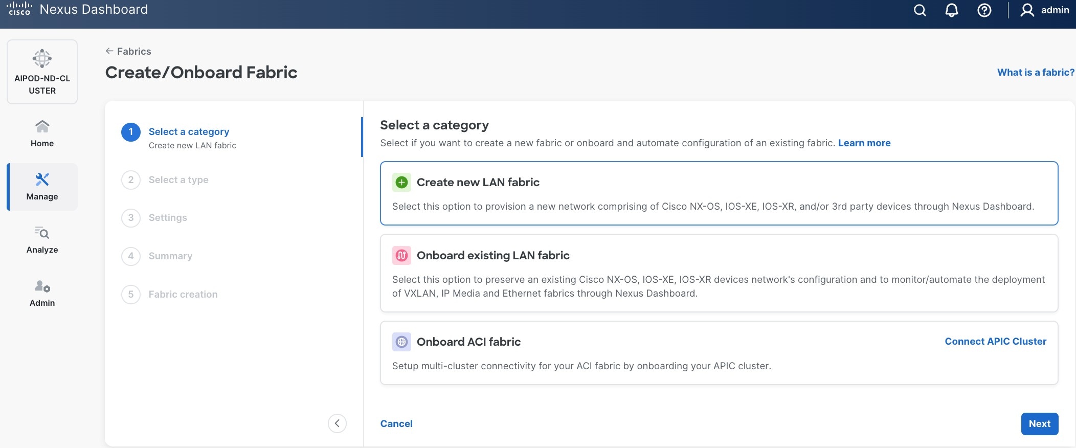
Step 5. Select Create a new LAN fabric.
Step 6. Click Next.
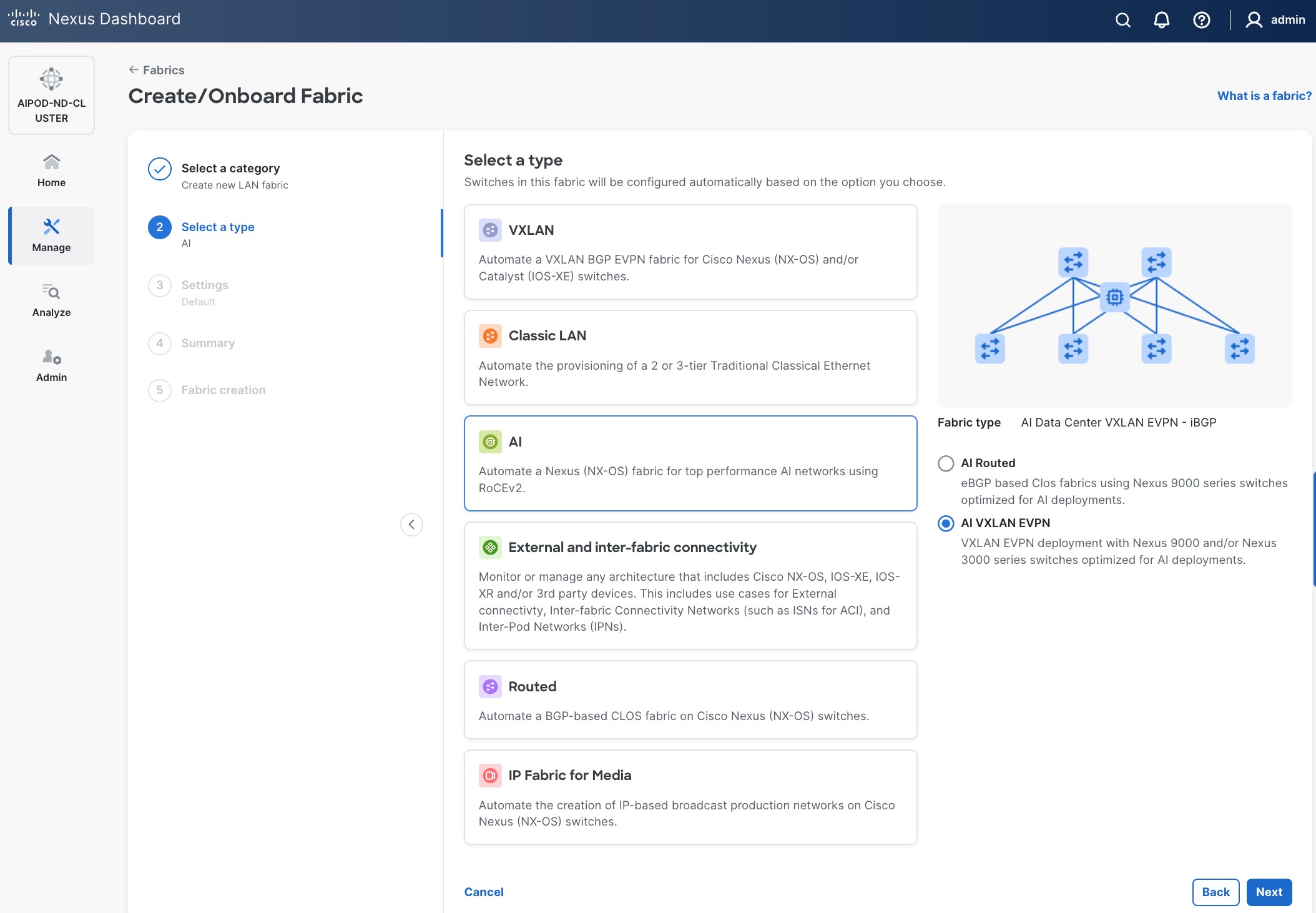
Step 7. For the Backend (E-W) AI/ML fabric, select AI > AI VXLAN EVPN to manage and setup a high-speed 400GbE/800GbE fabric for GPU-to-GPU connectivity.
Step 8. Click Next.
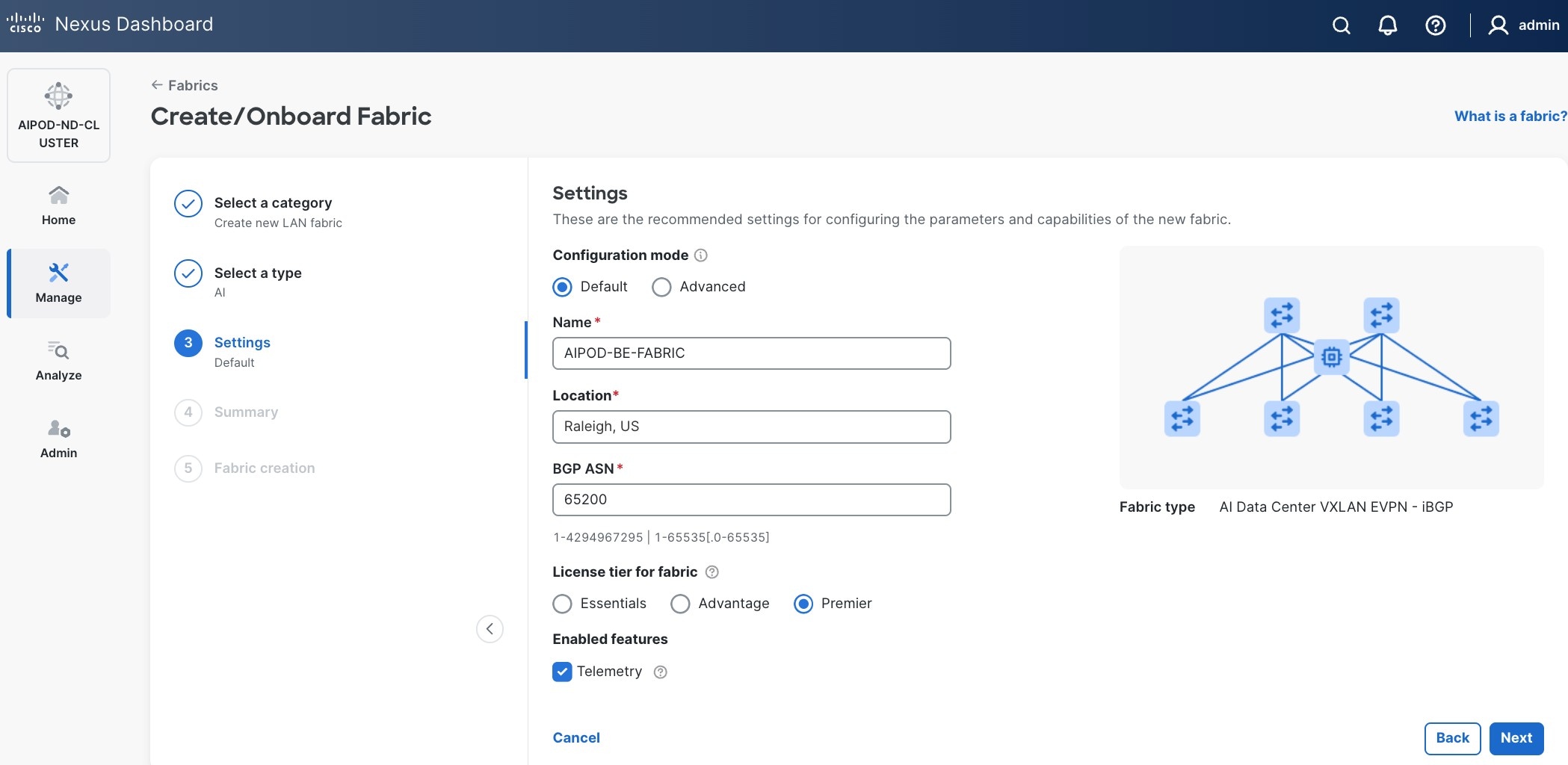
Step 9. To configure the Backend (BE) fabric, under Configuration Mode, specify the following:
a. Leave the radio button enabled for Default.
b. Specify Name, Location, and BGP ASN#.
c. Select one of the Licensing options for the fabric - see "?" icon to get more details on the options.
d. (Optional) Enable Telemetry feature.
Step 10. Enable the radio button for Advanced in the Configuration Mode section to see additional configuration options for the fabric.
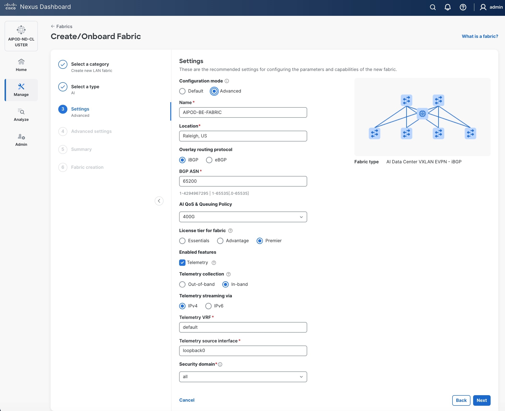
Step 11. Verify QoS and Telemetry settings reflect your setup.
Step 12. In the Advanced Settings menu, select the Resource tab.
Step 13. Click Next.
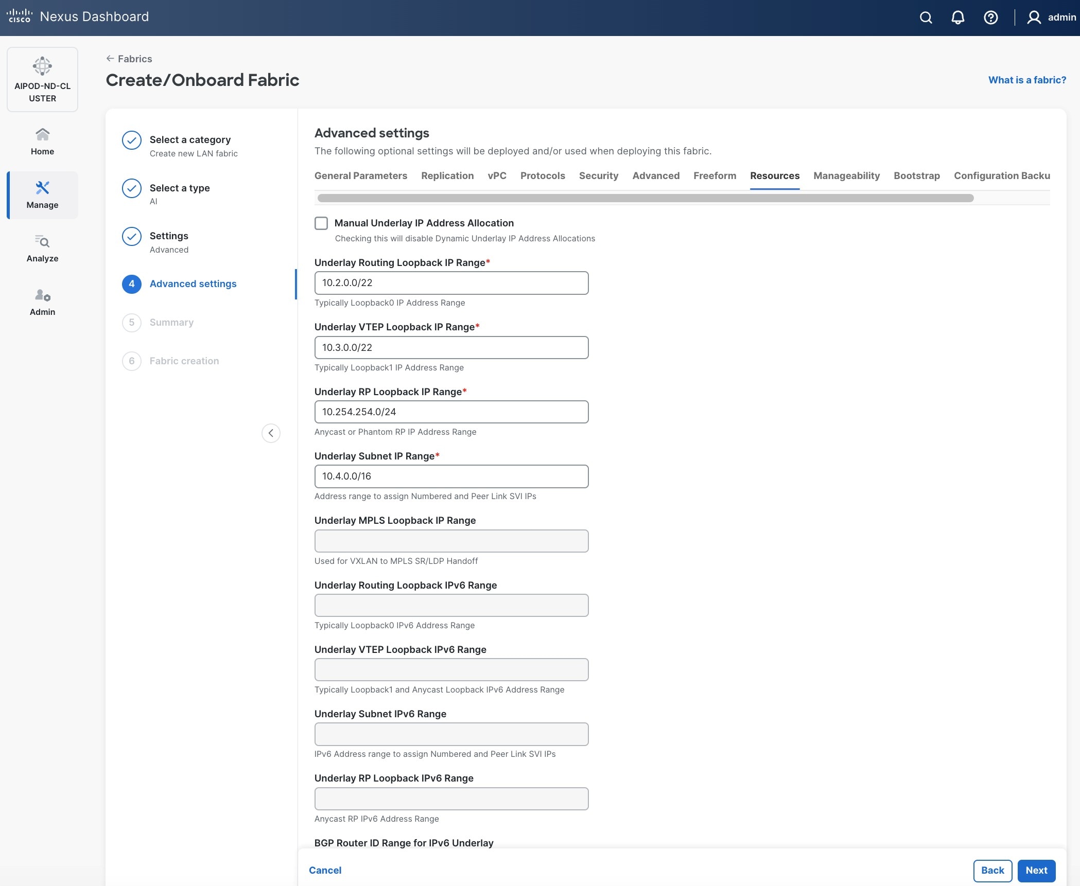
Step 14. Change the IP address for this fabric from the default values to prevent overlap with frontend fabric, also managed by the same Nexus Dashboard. For this CVD validation, the first octet was changed from 10 to 20. The Backend fabric is isolated from other networks with no external connectivity so it could be kept as frontend but there will be alerts and warnings on Nexus dashboard, so the change is primarily done for this reason.
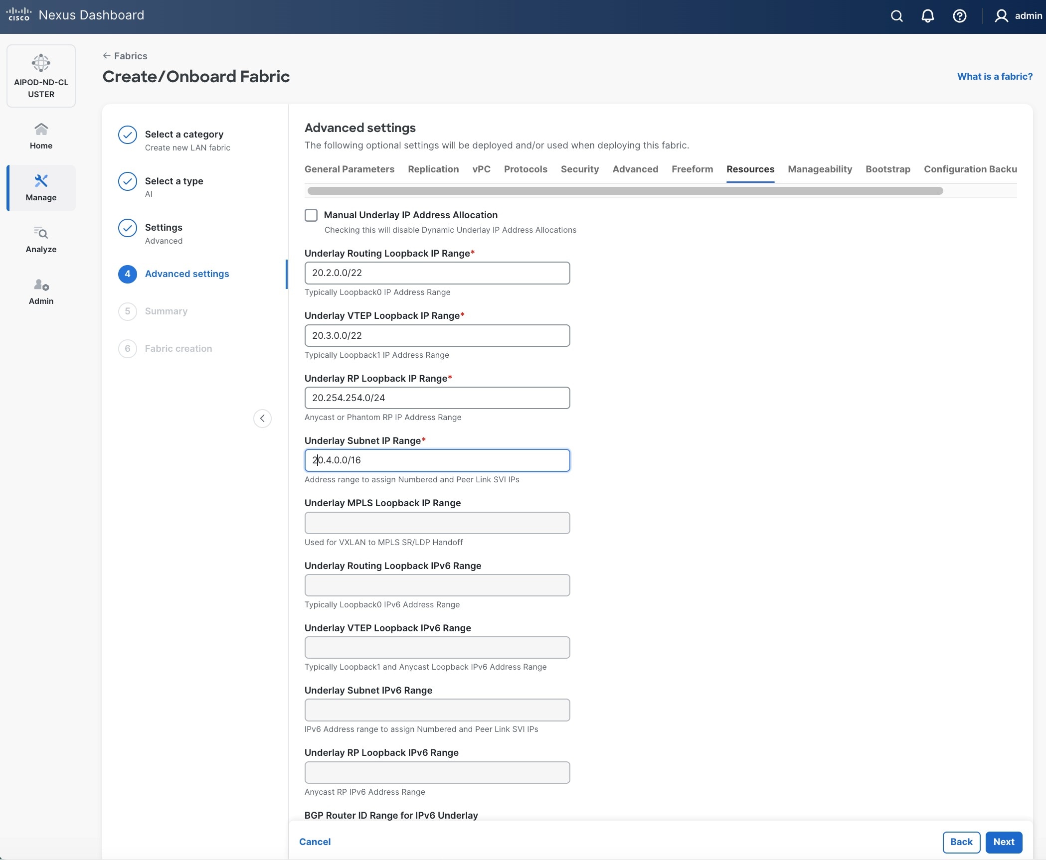
Step 15. Scroll down and change the VRF Lite Subnet IP Range.
Step 16. Click Next.
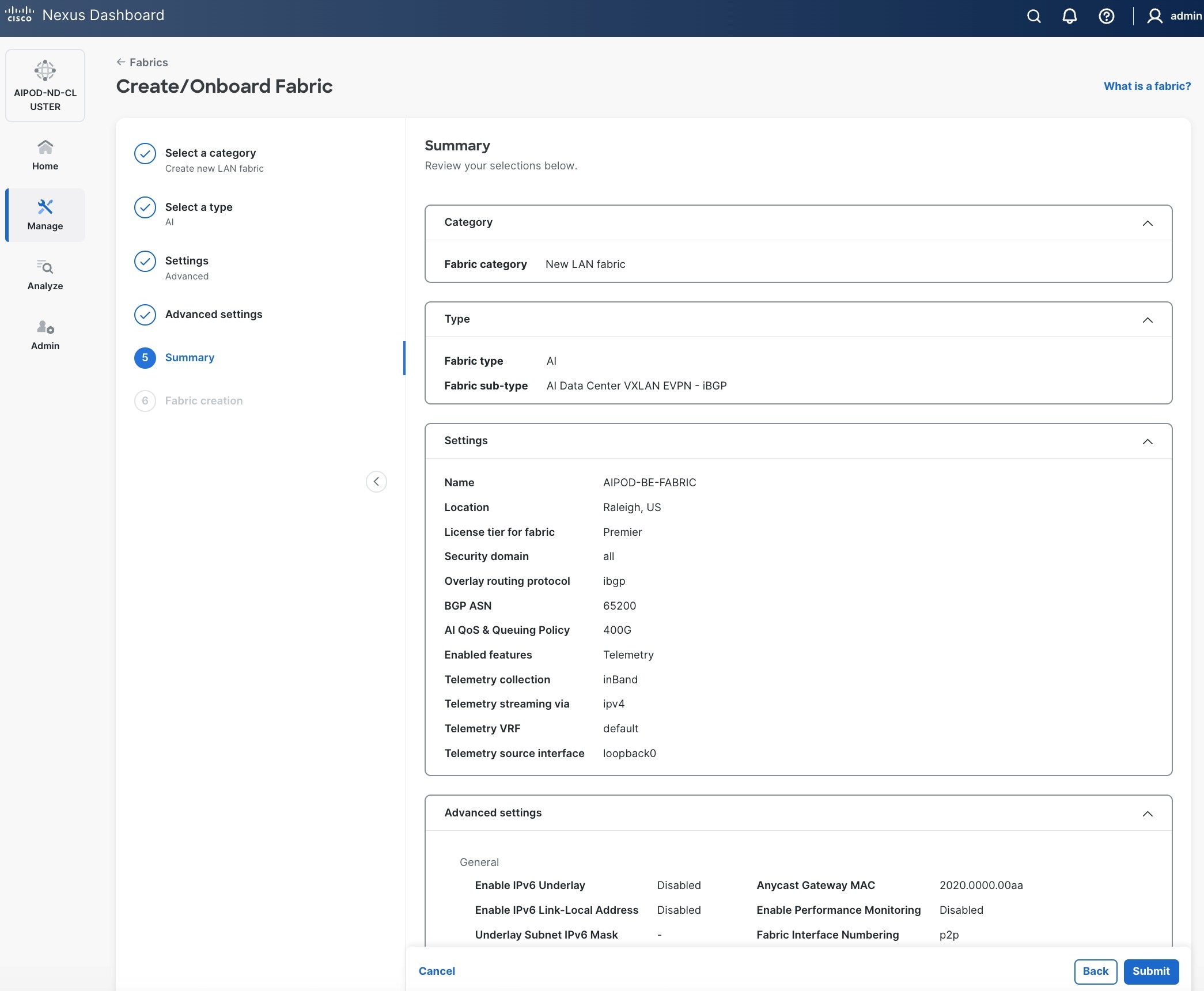
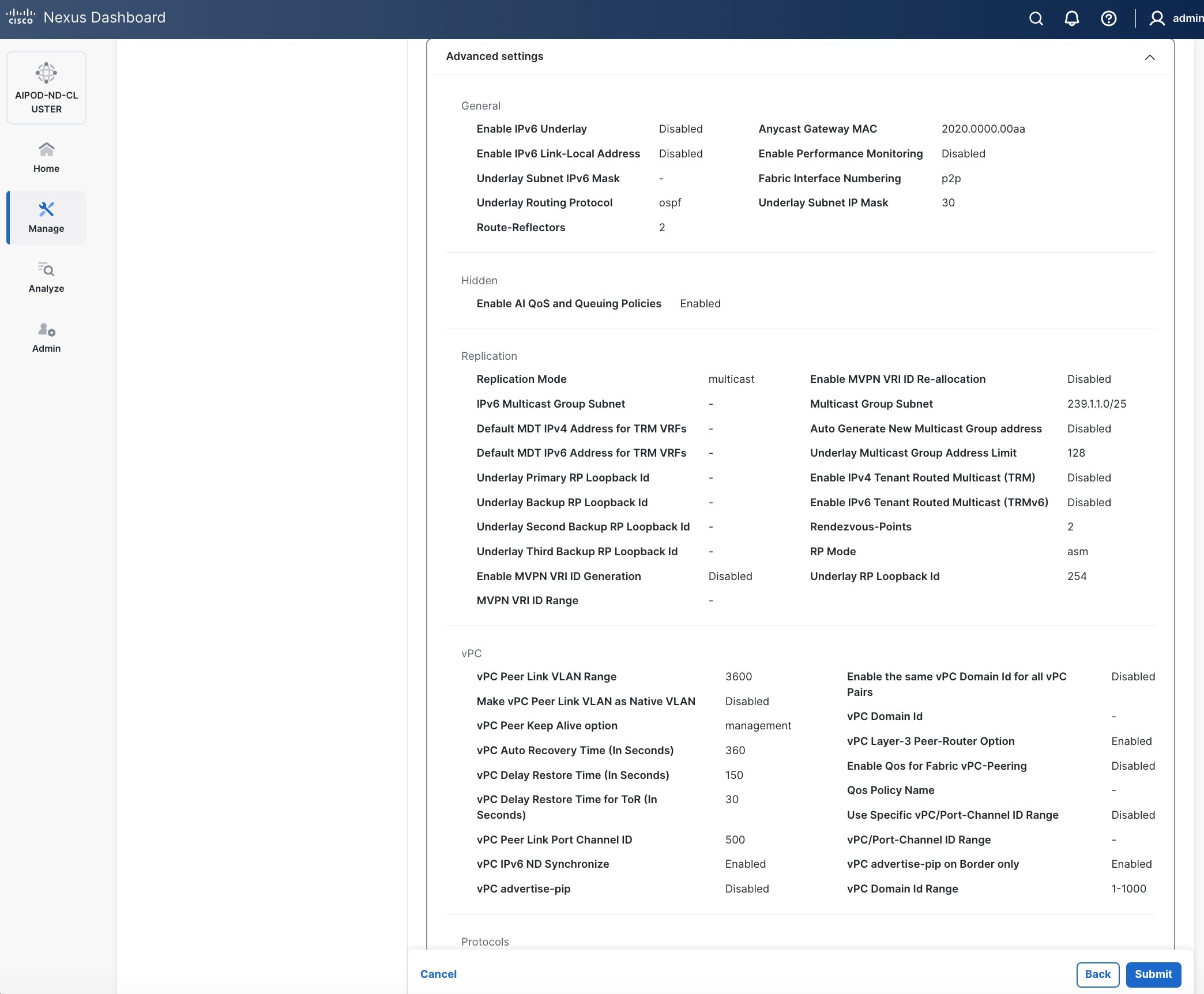
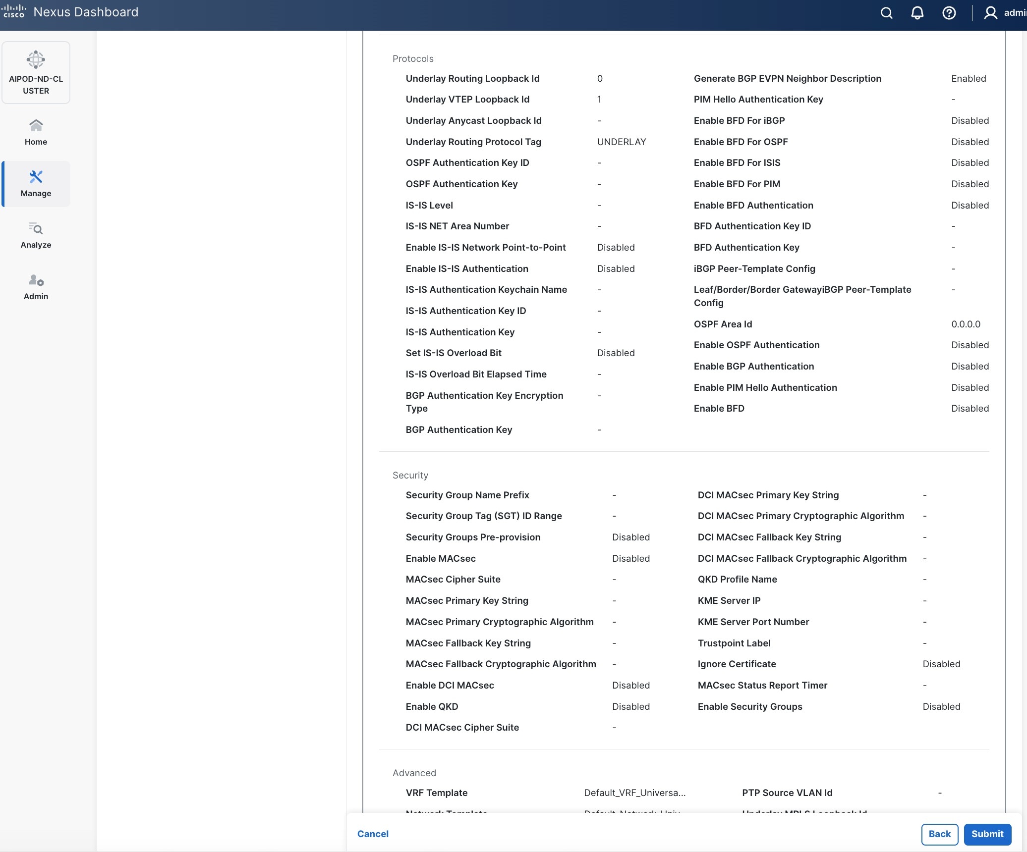
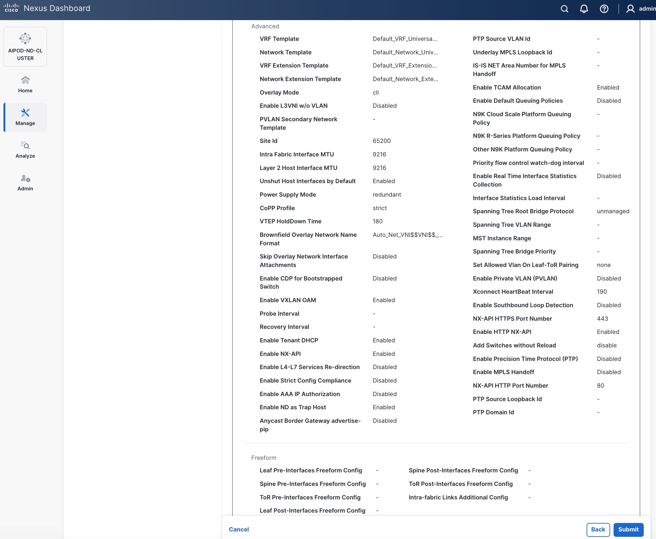
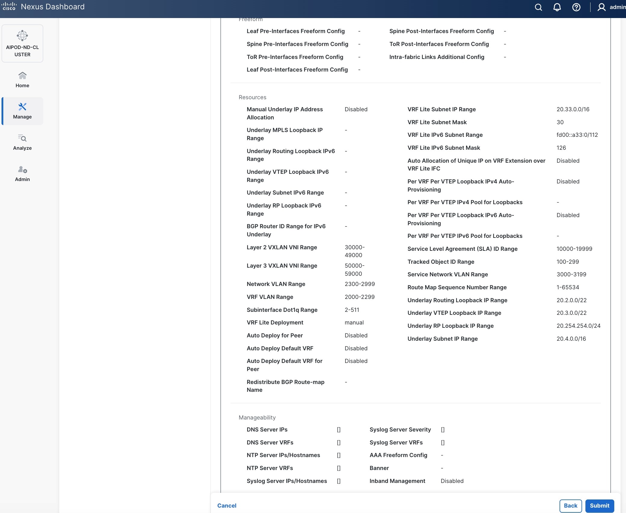
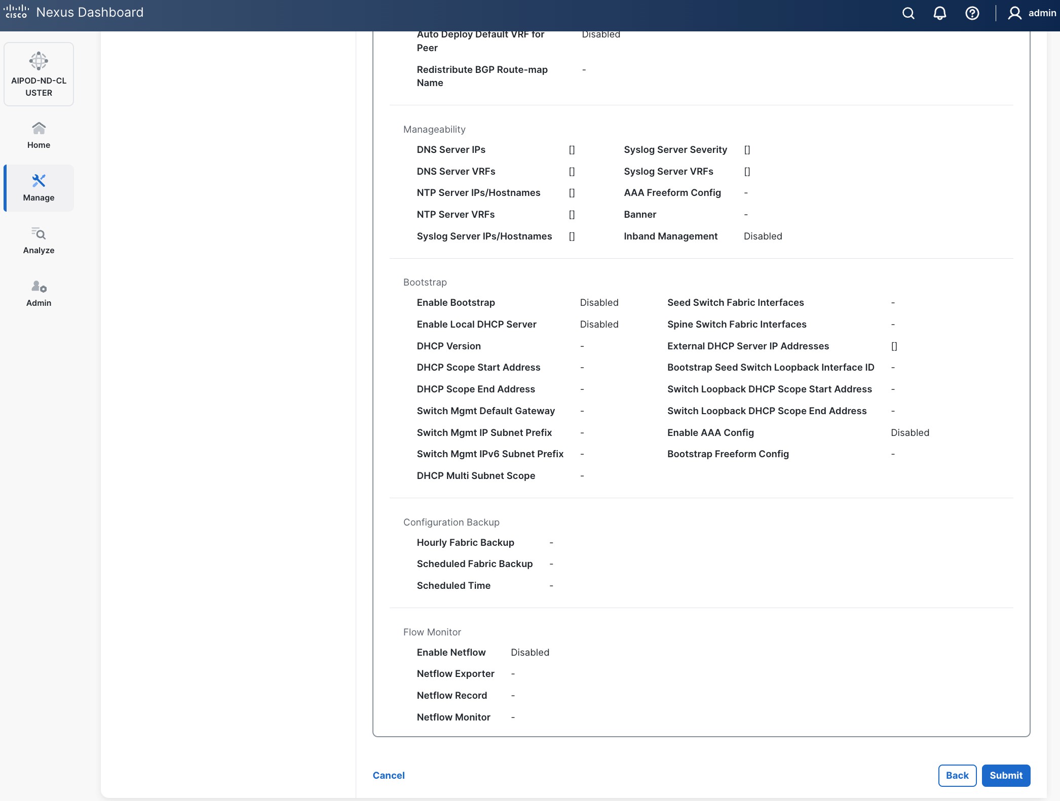
Step 17. Review the Fabric Summary settings.
Step 18. Click Submit.
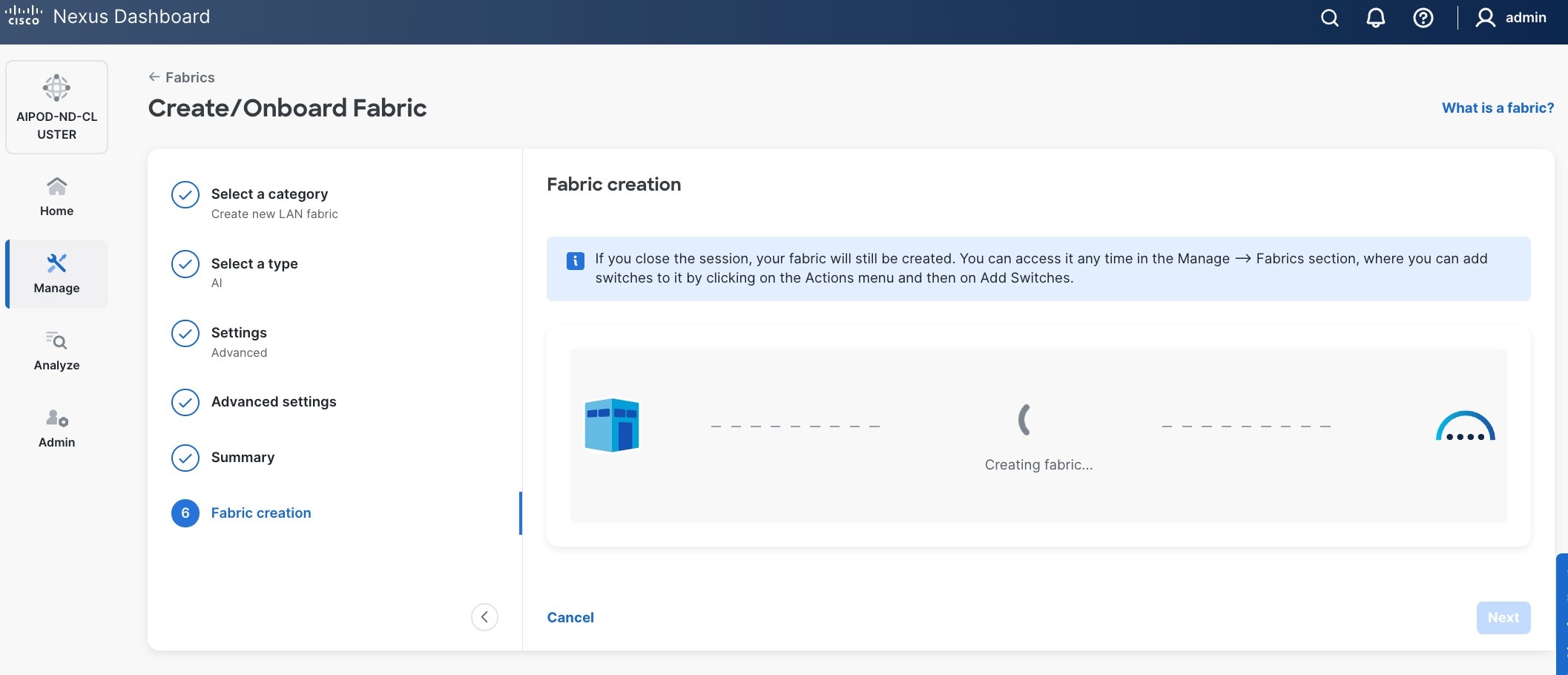
Step 19. Wait for the Fabric creation to complete.
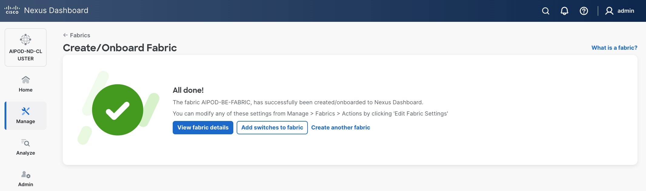
Step 20. Click View Fabric Details to see the dashboard for the newly created BE Fabric.
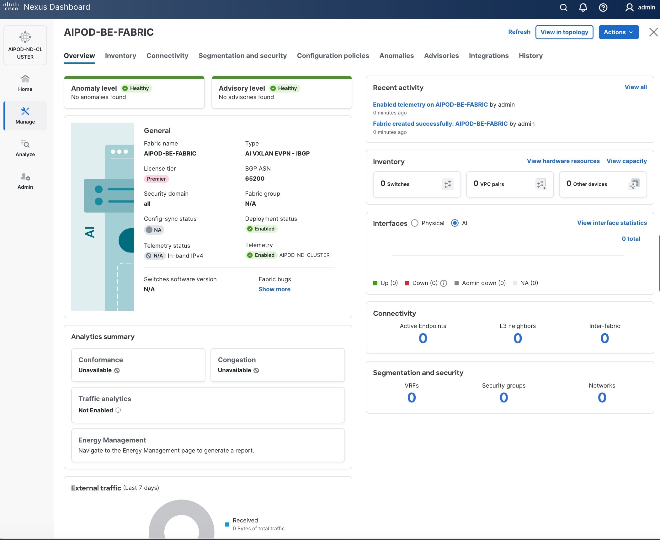
Step 21. Select Manage > Fabrics on the left and then select the BE fabric. From the Actions drop-down list, select Edit fabric settings. Select the Fabric management tab and the Manageability tab underneath. Add the NTP Server IPs and the NTP Server VRF (management) and click Save.
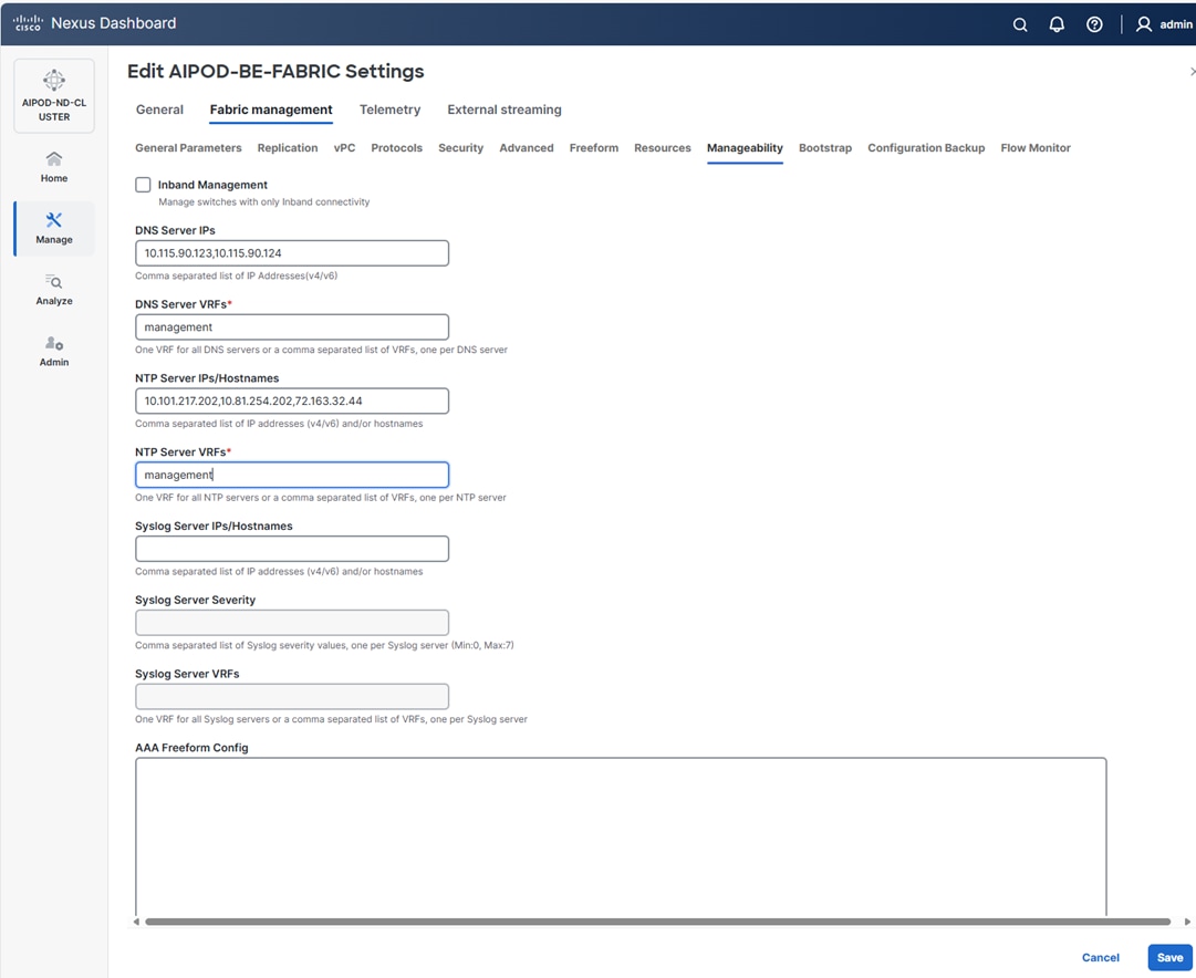
Step 22. Select the Freeform tab and optionally enter the info shown in the screenshot modified for your timezone. Click Save.
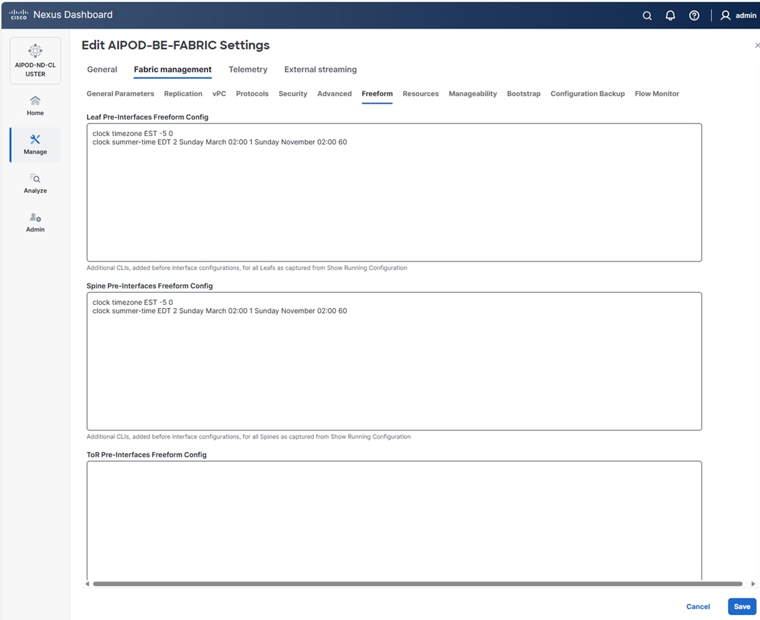
Procedure 2. Add Spine and Leaf switches to the BE Fabric
Step 1. If you want to add switches without a reload, go to Manage > Fabrics.
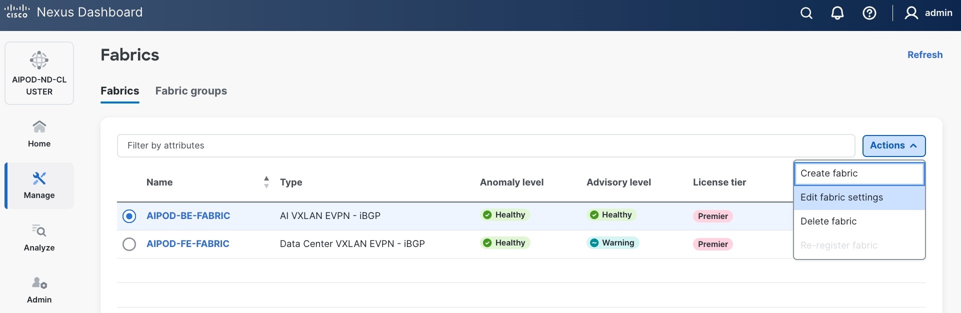
Step 2. From the Actions menu, select Edit Fabric Settings.
Step 3. Click Fabric Management > Advanced tabs and scroll down to find the field for Add switches without Reload and change setting to Enable. Click Save.
Step 4. In the Warning message, click Got it.
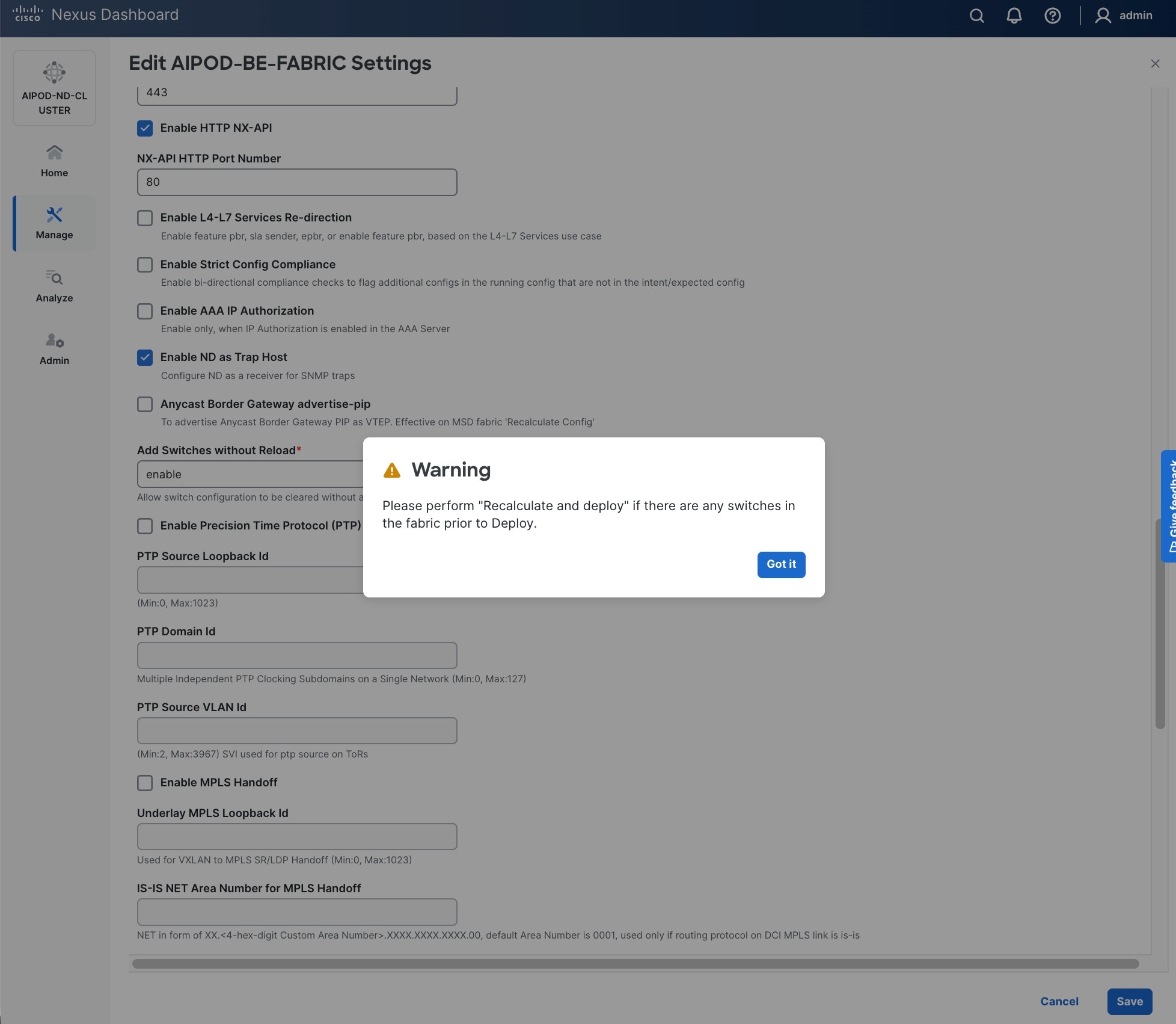
Step 5. From the Manage > Fabrics view, click the BE fabric name to add switches to the fabric.
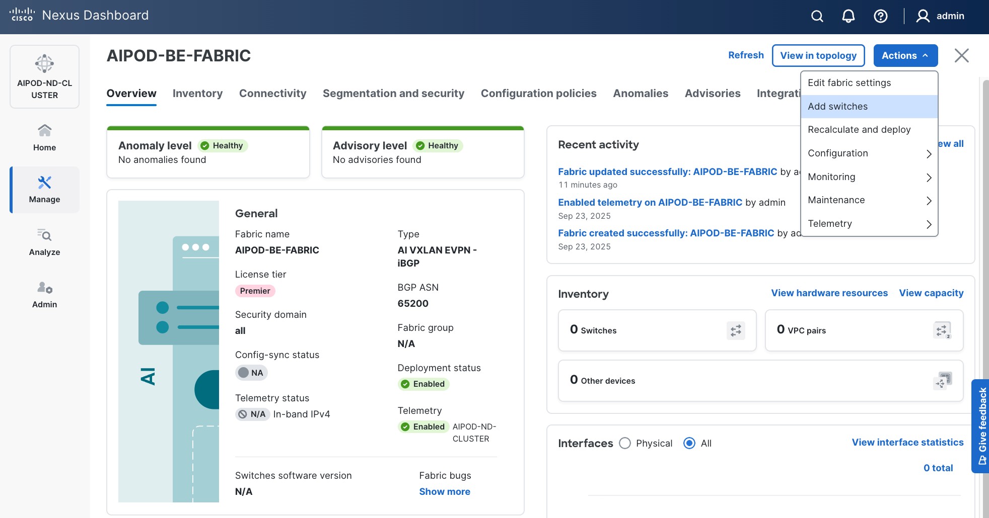
Step 6. Click Actions > Add switches. Specify the following:
● Seed IP
● Username and Password
● Number of hops
● Uncheck Preserver Config
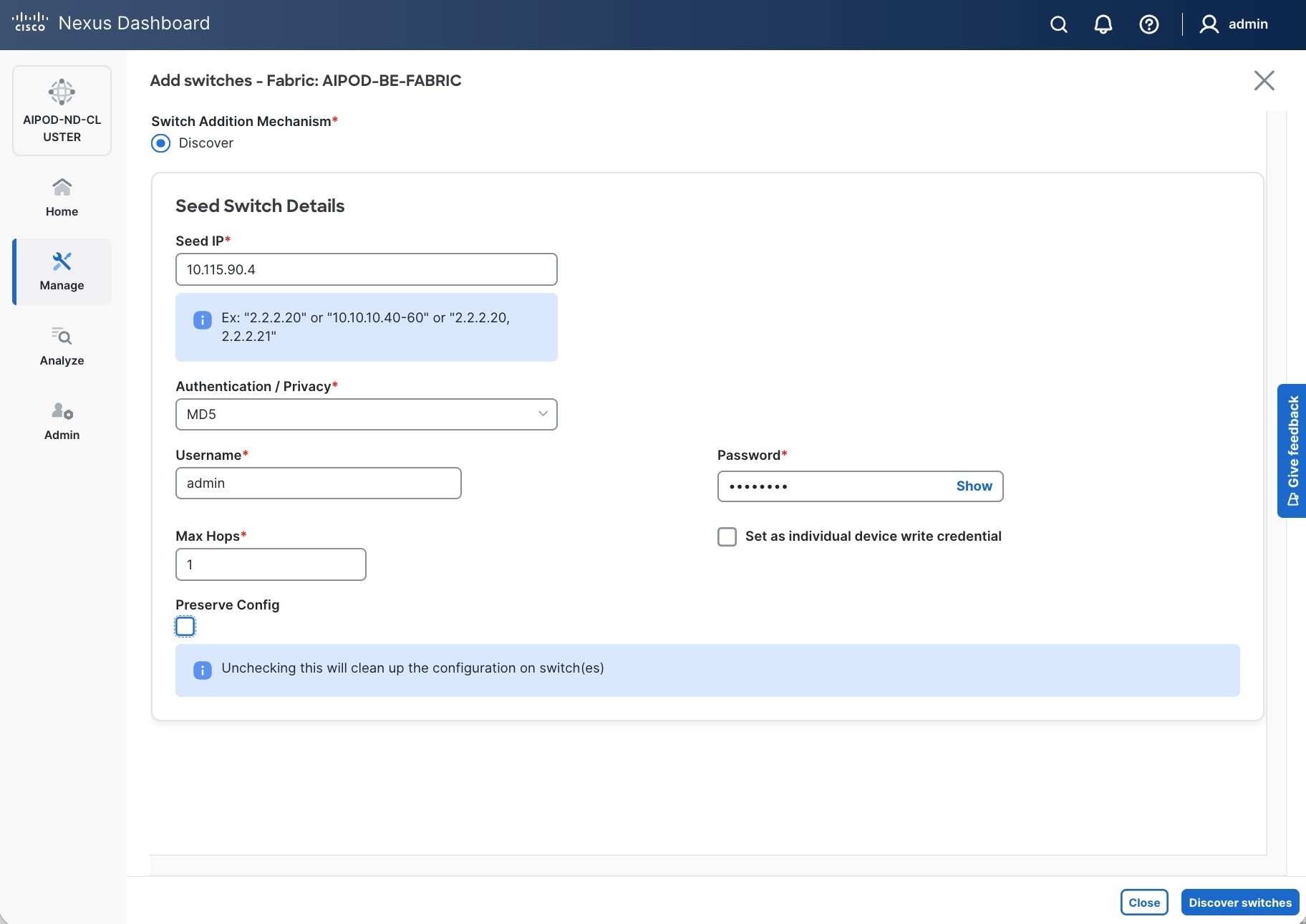
Step 7. Click Discover Switches.
Step 8. Click Confirm. Filter the discovered switch list as needed to view just the switches you want to add.
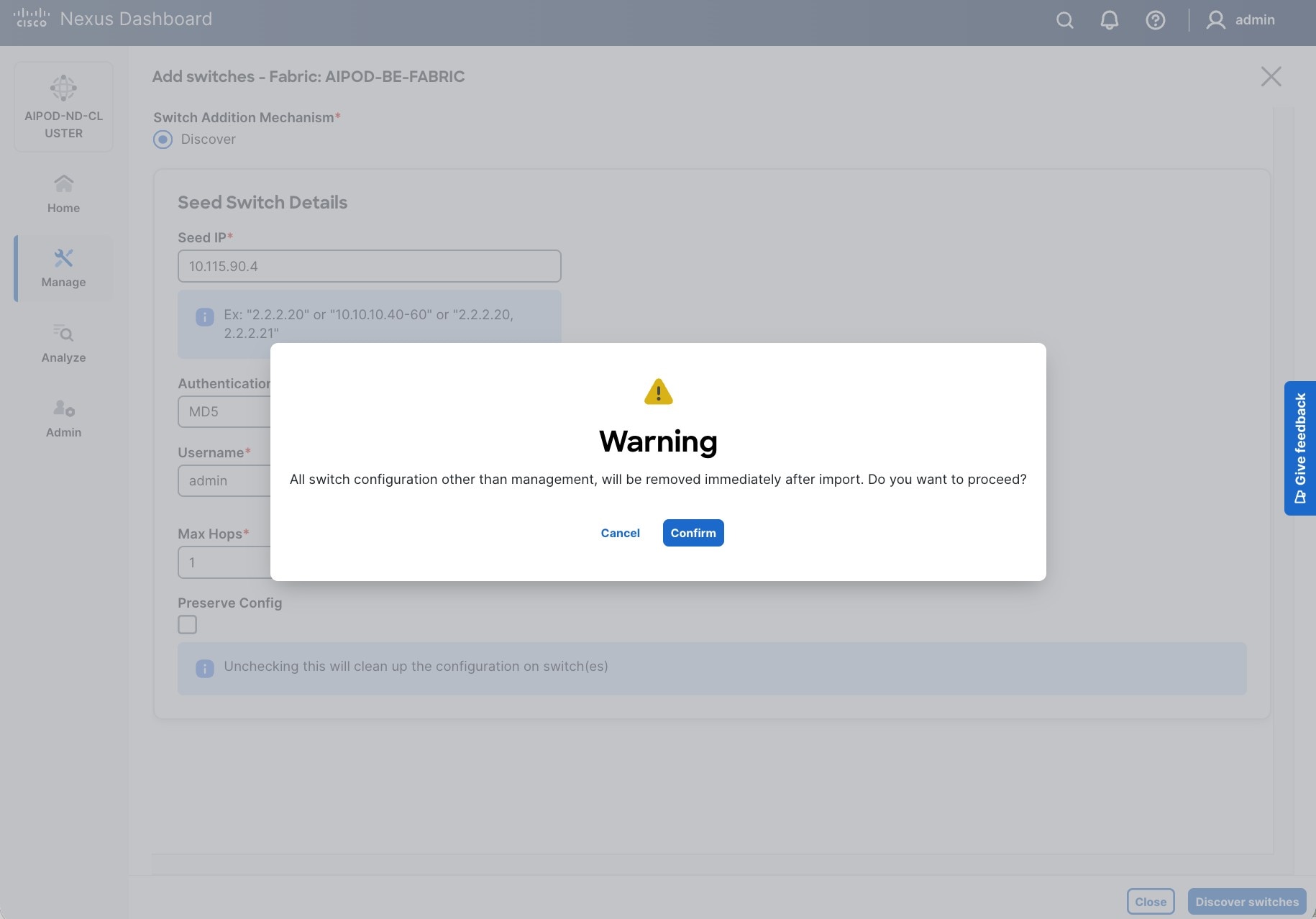
Step 9. Select the switches to add to the BE Cluster.
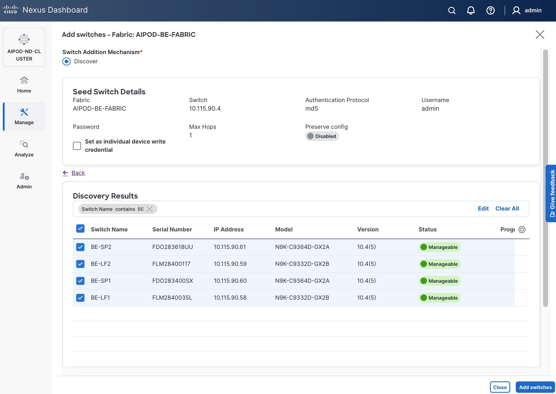
Step 10. Click Add Switches.
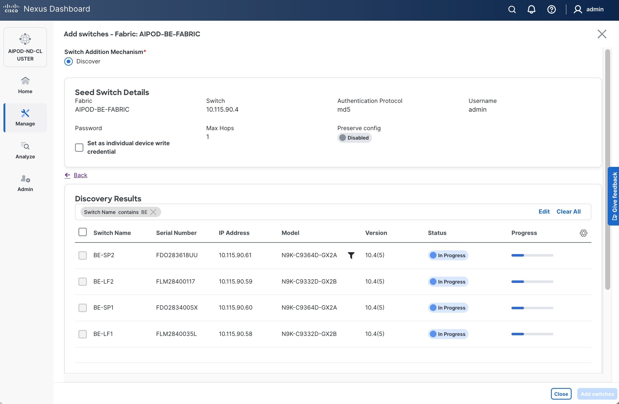
Step 11. When the Status changes from Status to Switch Added, click Close.
Step 12. From the Manage > Fabrics, select the fabric and click Inventory tab.
Step 13. For each switch in the list, verify Role is correct.
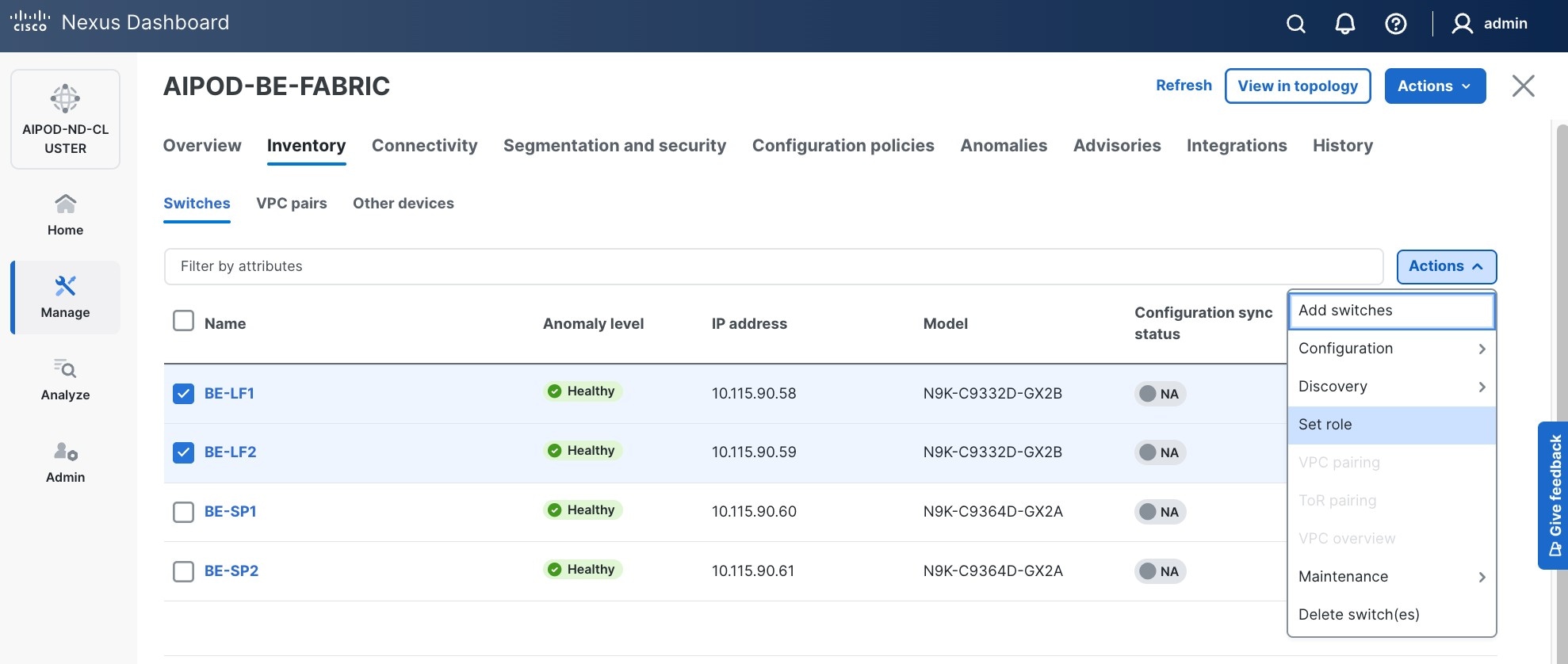
Step 14. To change the role, select the switch and then click Actions and select Set role from the drop-down list.
Step 15. In the Select Role pop-up window, select the correct role from the list and click Select.
Step 16. Click OK in the pop-up warning to perform Recalculate and deploy to complete the change.
Step 17. Repeat steps 14 - 16 to select role for all switches in the fabric.
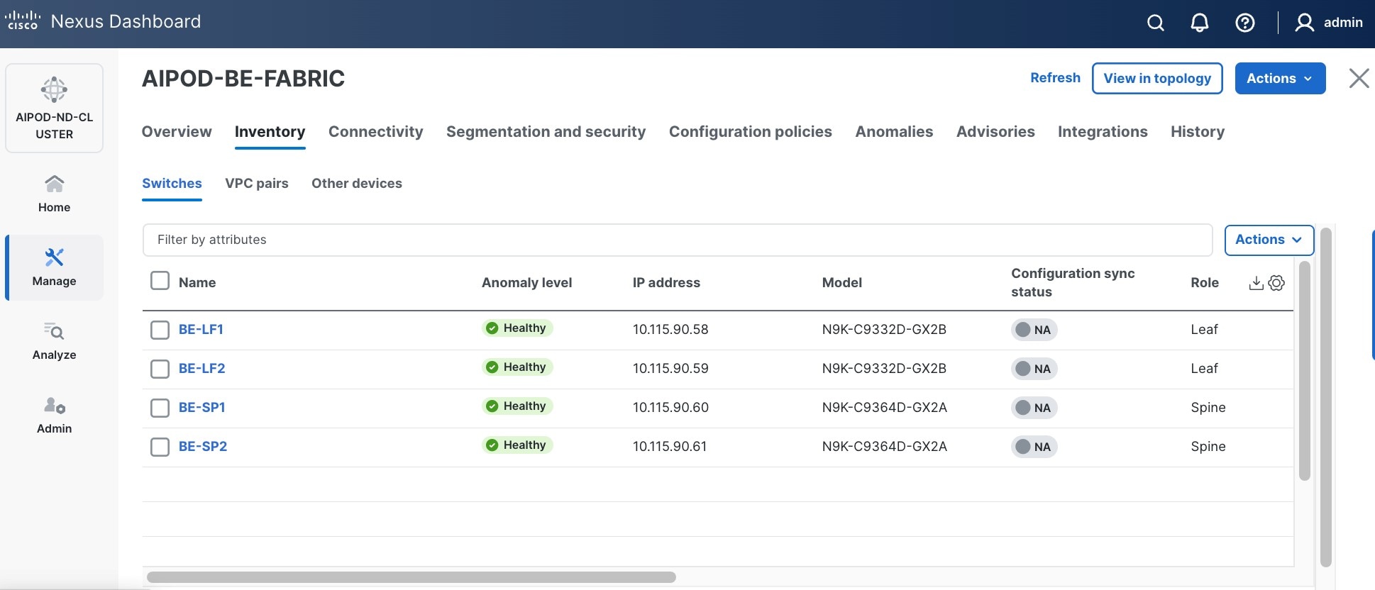
Step 18. Click the main Actions button and select Recalculate and deploy from the drop-down list. If it says one is already in progress, wait a few minutes and repeat the steps.
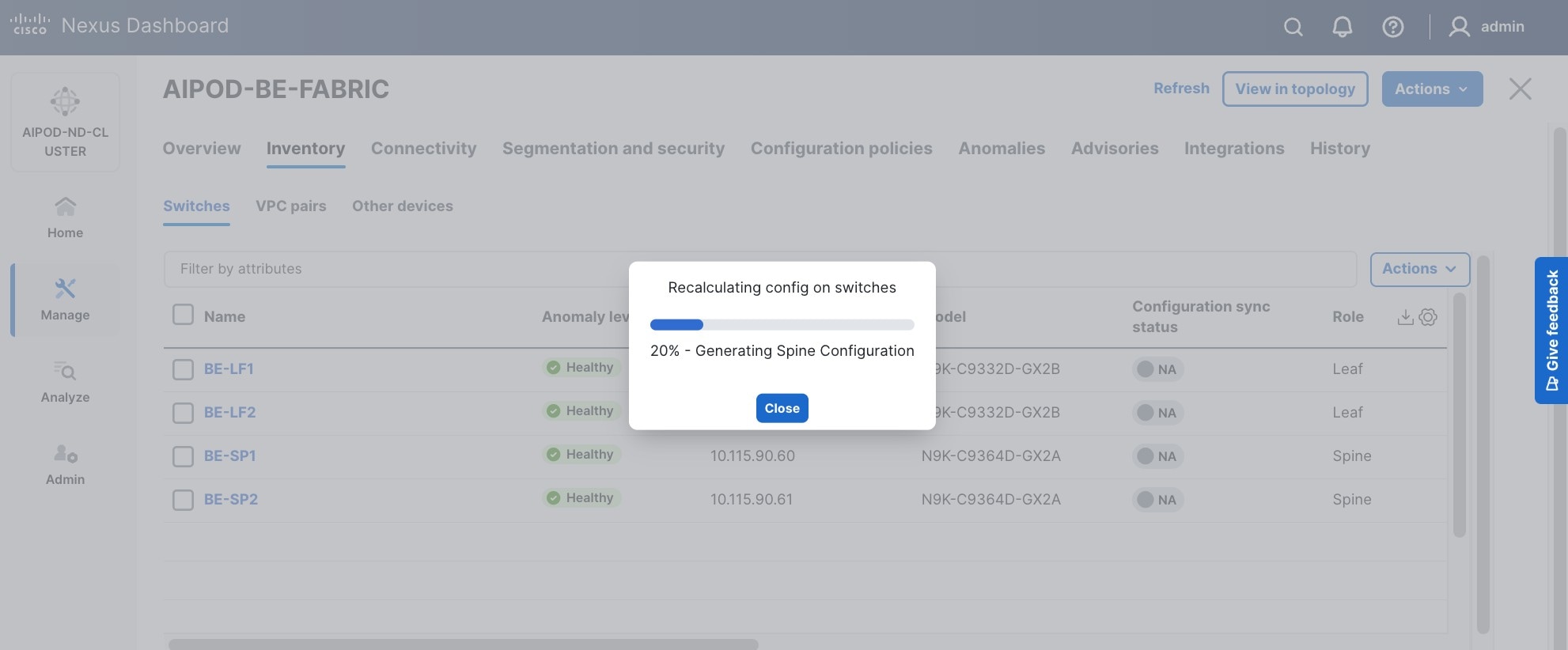
You should see the Fabric as Out-of-sync with some Pending Config (lines of config) changes from the recalculation as shown below:
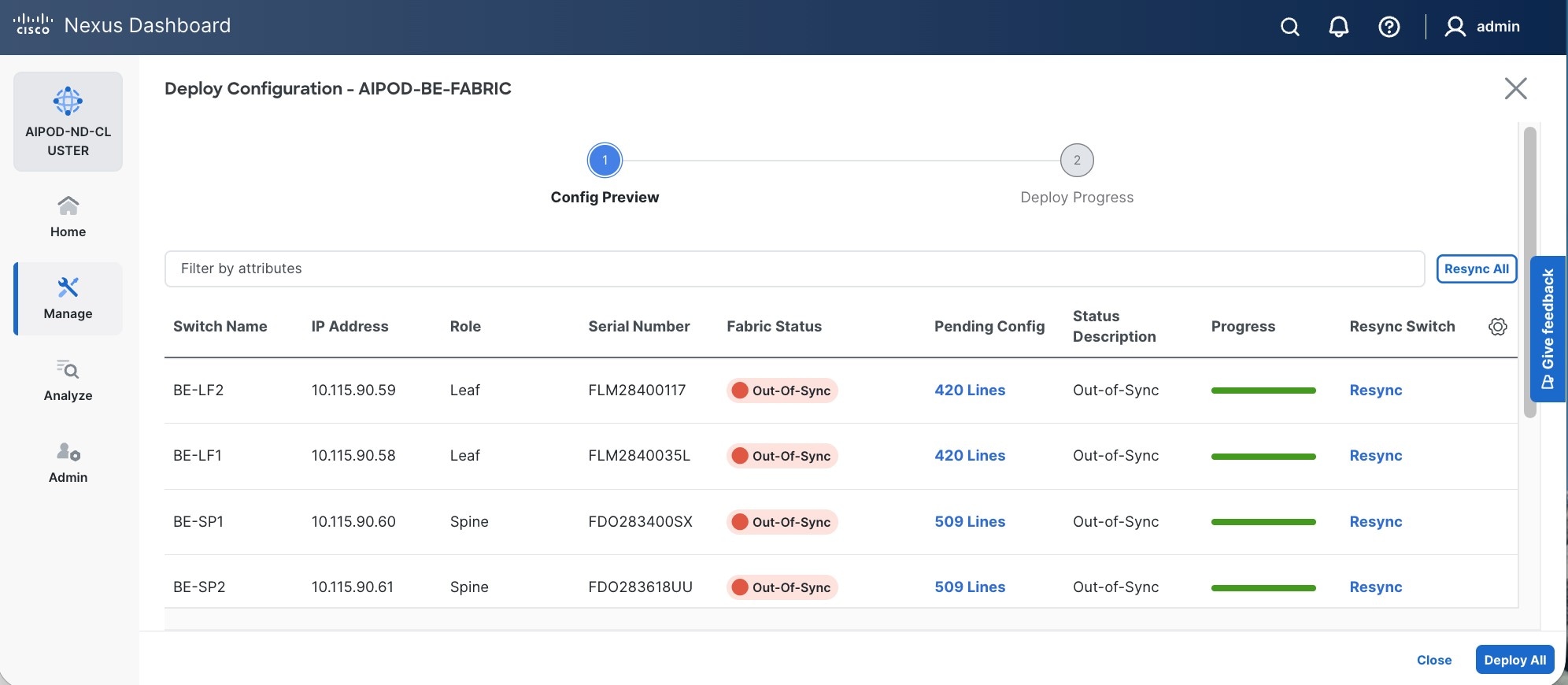
Step 19. Click the Pending Config lines for any of the switches to view the exact changes that will be deployed. Click Close.
Step 20. Click Deploy All.
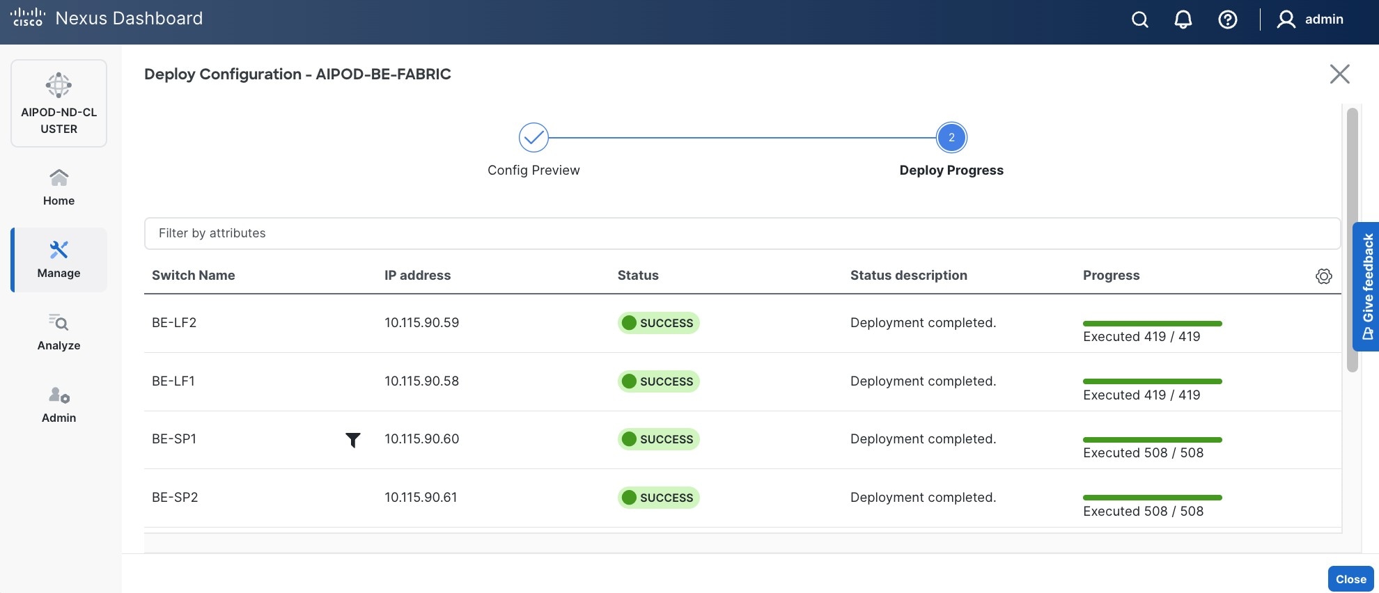
Step 21. When the configuration deployment completes successfully, click Close.
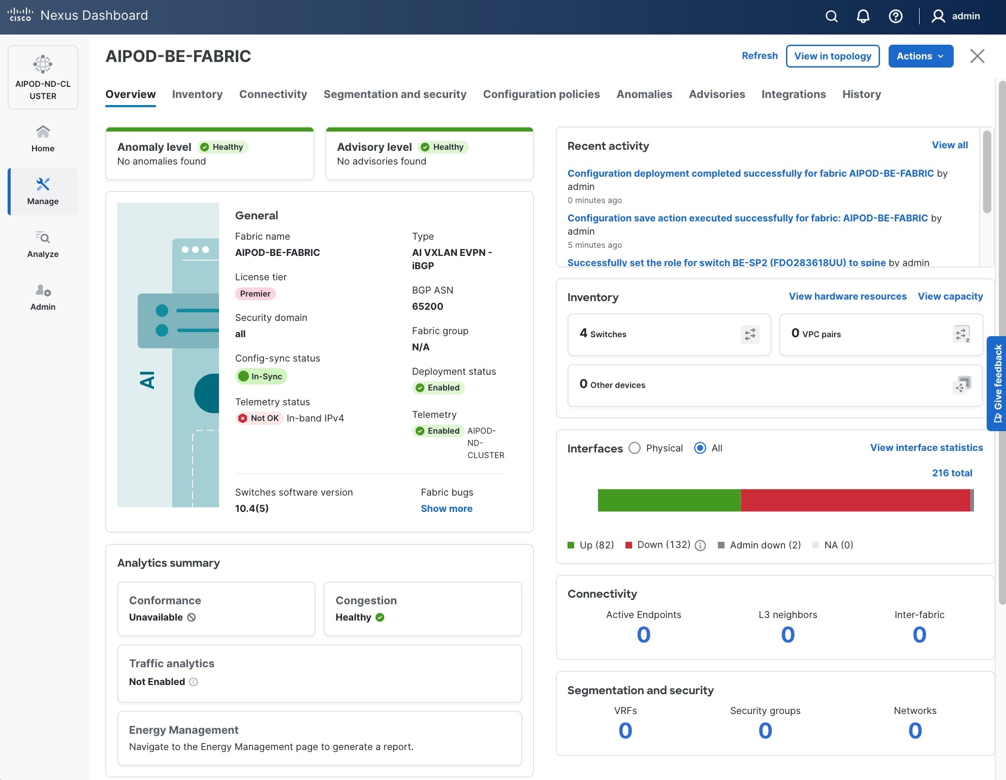
Procedure 3. Review fabric state and upgrade software as needed
Step 1. ND may identify issues in hardware, connectivity, software and so on, reflected by the Anomaly level. To view the flagged anomalies, go to Anomalies in the top menu bar. Address each anomaly to prevent issues later, either by resolving them or acknowledging them.
Step 2. Review the Advisories and resolve or acknowledge them.
Step 3. Evaluate and upgrade to the most current Cisco recommended Nexus OS release.
Step 4. The BE fabric is now ready for connecting to UCS GPU nodes to enable GPU-to-GPU communication across the BE fabric.
Modify QoS Policy on BE Fabric
Assumptions/Prerequisites
Assumes that you have selected the AI Fabric template with default QoS policy enabled. This section will modify this default policy for the software version used in this CVD.
Setup Information
Table 20. Setup Information for BE Fabric QoS
| Parameter Type |
Parameter Name | Value |
Parameter Type / Other Info |
| QoS Policy Template |
|
|
| Default/Original Policy Template Name |
400G | AI_Fabric_QOS_400G |
|
| New Policy Template Name |
AIPOD-BE-QOS-400G |
|
| PFC MTU |
9216 |
Default for this release: 4200 |
| Bandwidth Percent for ‘c-out-8q-q3’ |
90 |
Default = 50 |
| Bandwidth Percent for ‘c-out-8q-q-default’ |
90 |
Default = 50 |
Deployment Steps
To change the QoS policy deployed in the backend fabric, follow the procedures below using the setup information provided above.
Procedure 1. Create new template from default QoS policy template
Step 1. Use a web browser to navigate to Cisco Nexus Dashboard. Use the management IP of any node in the ND cluster. Log in using admin account.
Step 2. Navigate to Manage > Template Library.
Step 3. Filter on ‘QOS’ in top search bar.
Step 4. Select the default QoS policy that was applied when the BE fabric was deployed using the default AI fabric template.
Step 5. Click Actions.
Step 6. Select Duplicate template from the drop-down list.
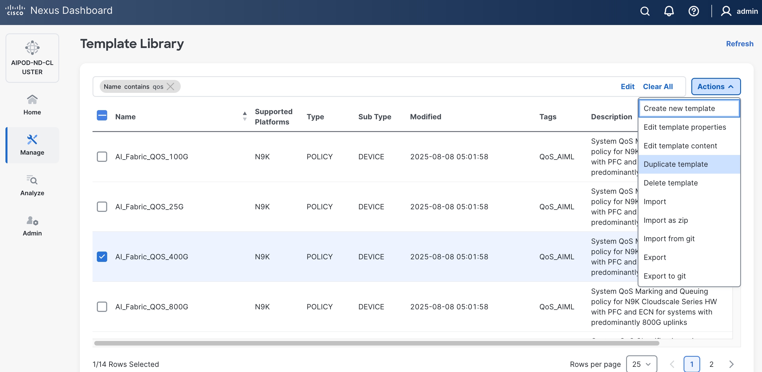
Step 7. In the Template Properties section, specify a new name for the QoS policy template.
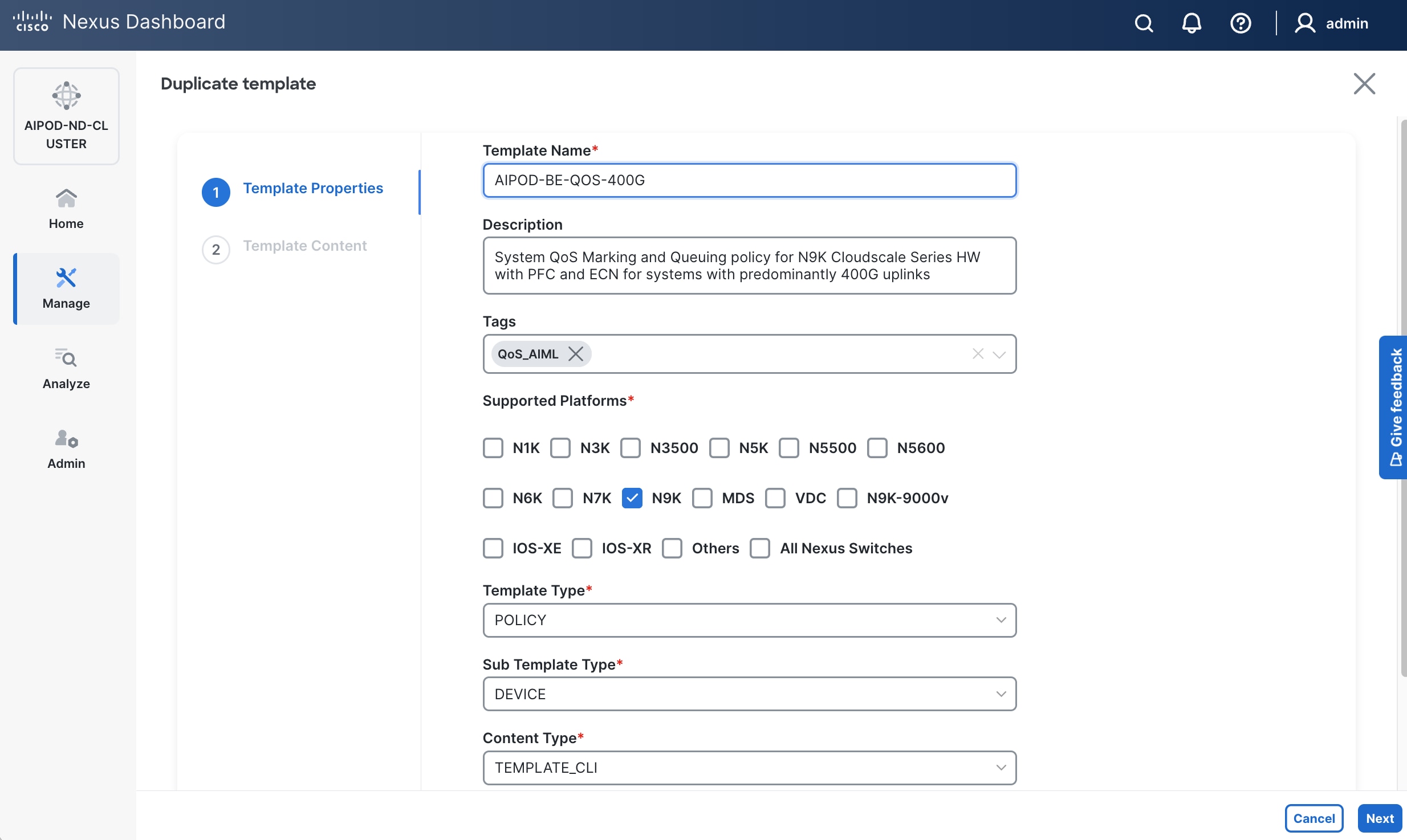
Step 8. In the Template Content section, modify the bandwidth percent for two queues: c-out-8q-q3 to 90 and c-out-8q-q to 10. Also, scroll down and change PFC MTU to 9216.
Note: Bandwidth Percent for the above queues can be adjusted as needed for your environment.
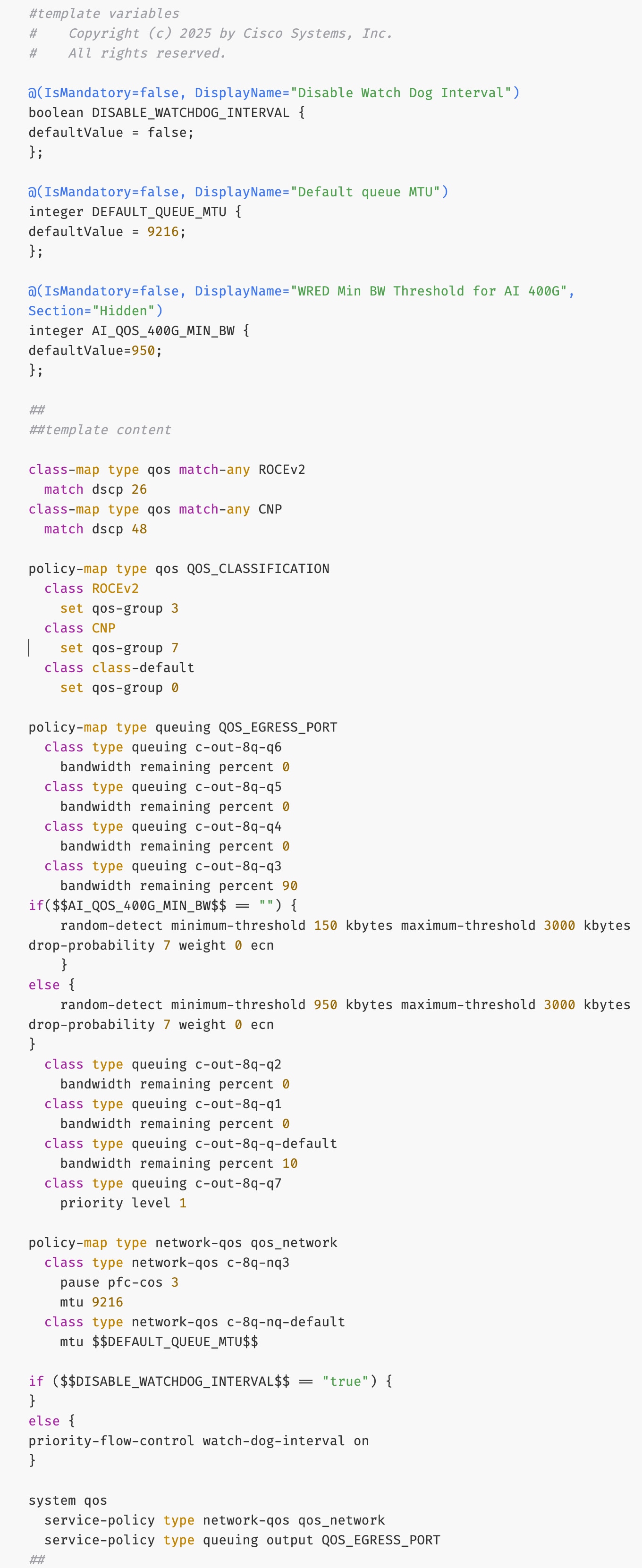
Step 9. Go to Manage > Fabrics. Select the BE fabric from the list and click the BE fabric name.
Step 10. Go to Actions and Edit Fabric Settings from the drop-down list. In the General tab, select the new QoS policy template from the drop-down list for AI QoS & Queueing Policy.
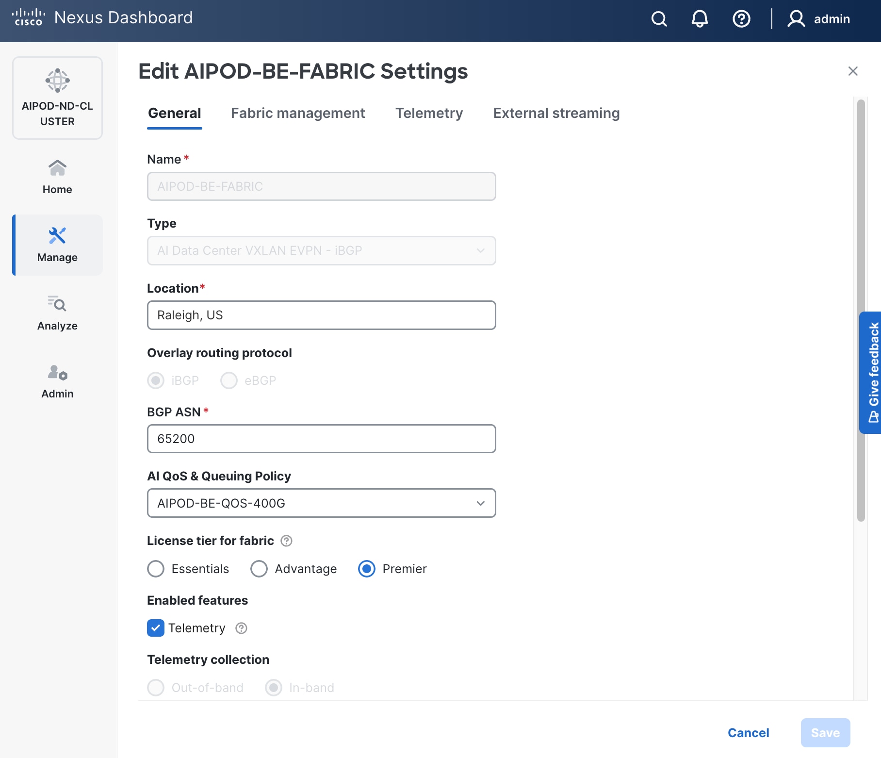
Enable GPU-to-GPU Networking between UCS GPU Nodes across BE Fabric
Assumptions/Prerequisites
Setup Information
Table 21. Setup Information for GPU-to-GPU networking across BE Fabric
| Parameter Type |
Parameter Name | Value |
Parameter Type / Other Info |
| BE Network |
|
|
| Network Name |
BE-MLPerf_VNI_33590 |
|
| Layer 2 Only |
Enable checkbox |
|
| Network ID |
33590 |
|
| VLAN ID |
3590 |
|
| VLAN Name |
BE-MLPerf_VLAN_3590 |
|
| Interface Description |
BE-MLPerf_VLAN |
|
| Ports Connecting to UCS Servers |
Assumed to be same on all leaf switches |
|
| Interface List |
Ethernet 1/1-8 |
|
| Port type |
Access port (int_access_host) |
Default = trunk port (int_trunk_host) |
| Enable port type fast |
Enable checkbox |
|
Deployment Steps
To enable GPU-to-GPU network between UCS GPU nodes across the backend fabric, follow the procedures below using the setup information previously provided.
Procedure 1. Configure ports going to UCS GPU nodes
Step 1. Filter the relevant interfaces going to UCS GPU nodes.
Step 2. Select the ports. Click the second of two Actions and select Configuration > Shutdown from the drop-down list to administratively shut the ports going to UCS GPU nodes.
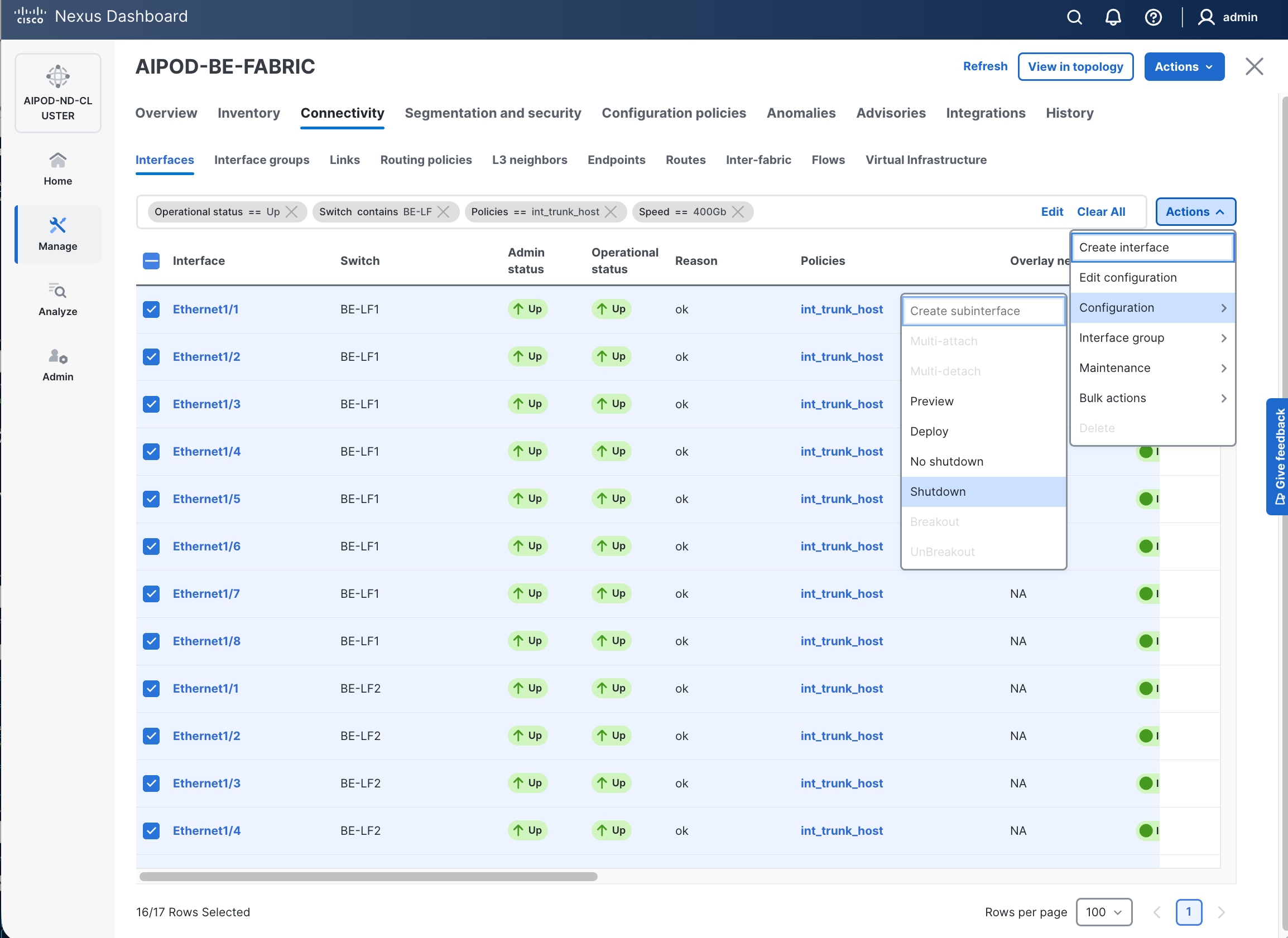
Step 3. Select the shutdown ports. Click the second of two Actions and select Edit Configuration to configure all ports going to UCS GPU nodes.
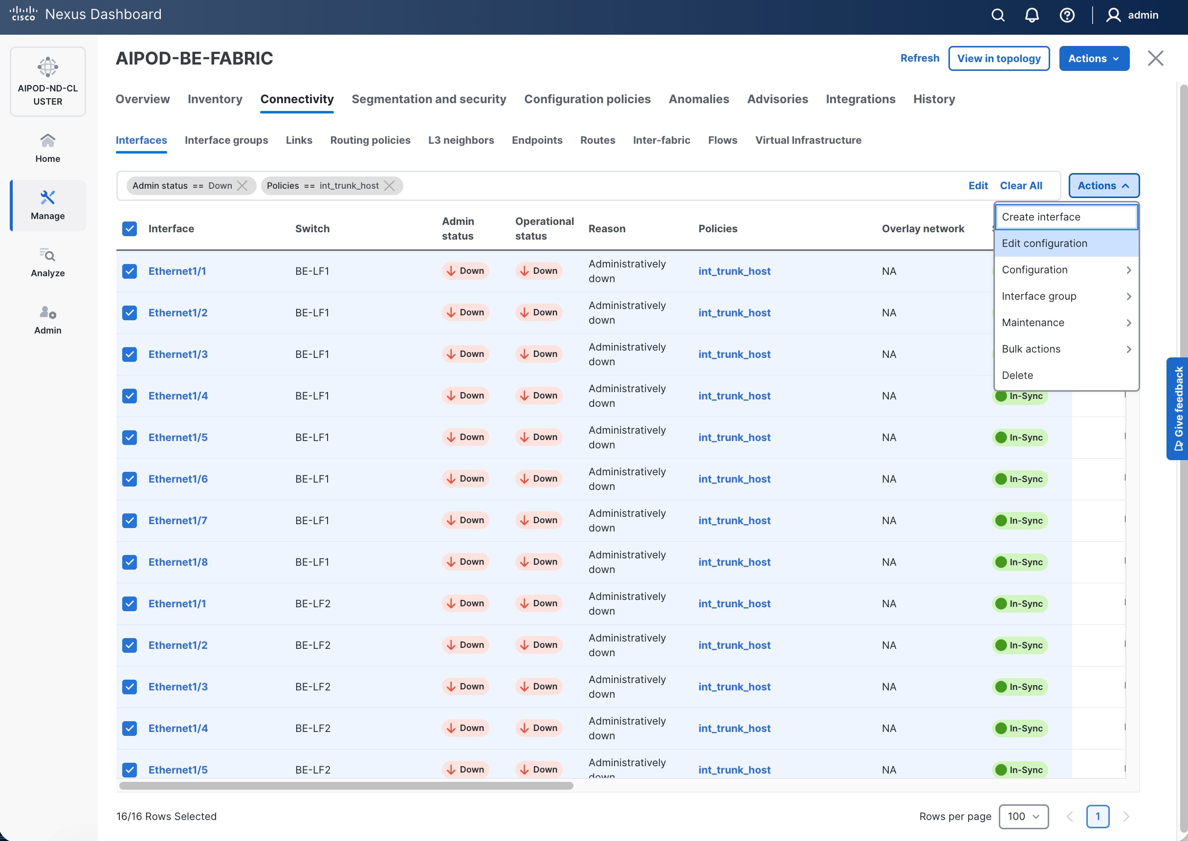
Step 4. Configure the first port going in the above list.
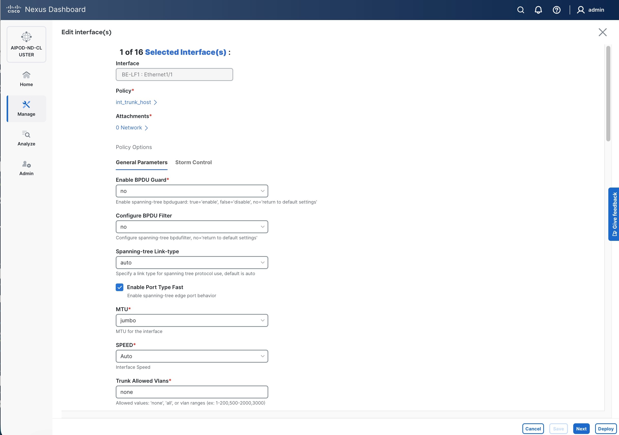
Step 5. Click int_trunk_host under Policy. In the Select Attached Policy Template pop-up window, select int_access_host from the drop-down list.

Step 6. Click Select.
Step 7. Make any other changes as needed. Click Save and click Next until all ports have been configured.
Step 8. Click Save.
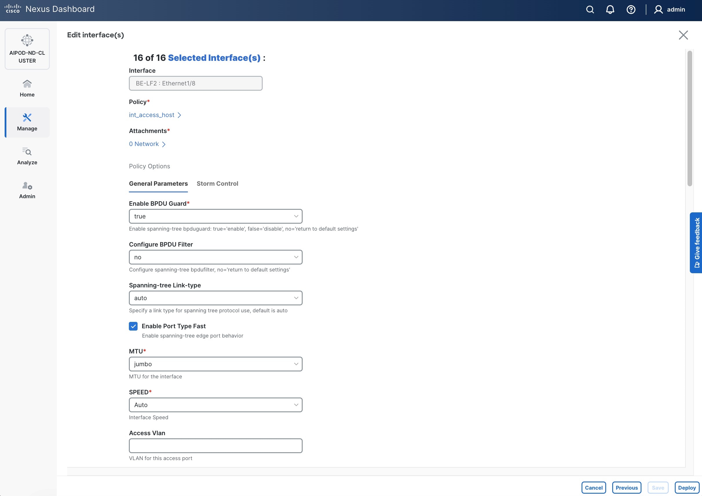
Step 9. Click Deploy.
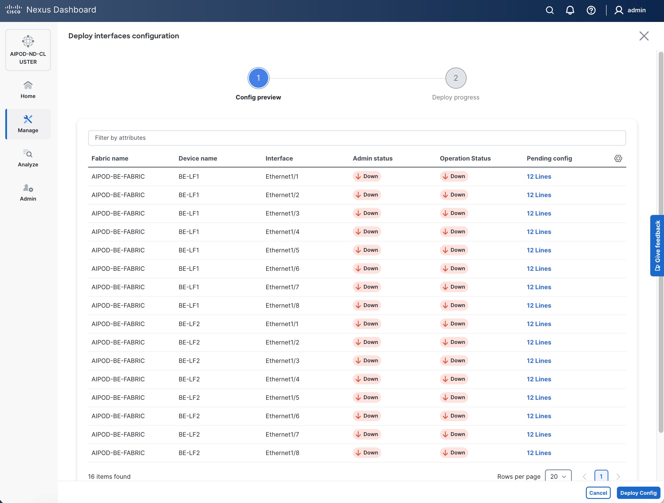
Step 10. Click the line count for each port in the Pending Config column to see the configuration being deployed.
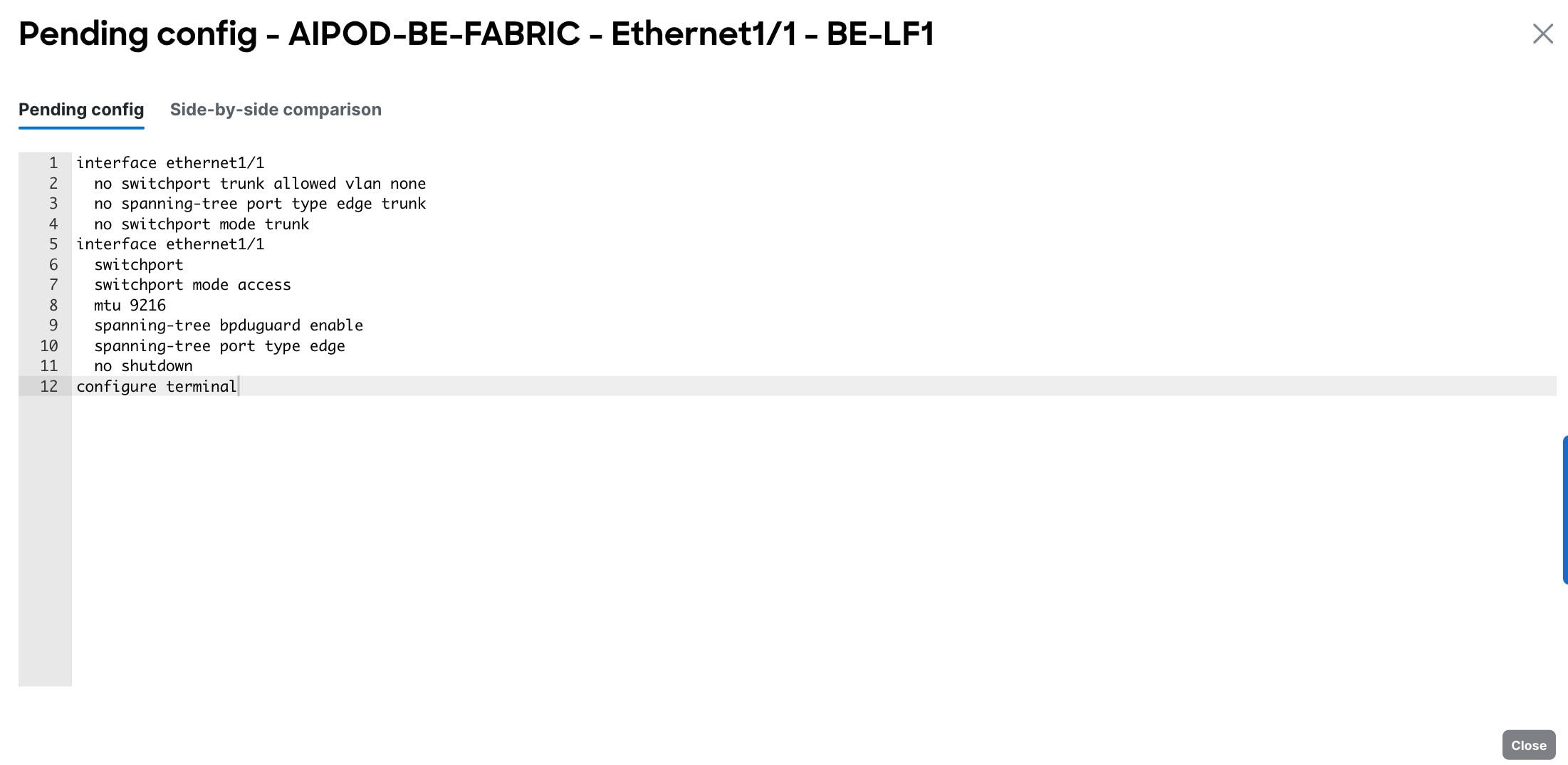
Step 11. Click Close.
Step 12. Click Deploy Config.
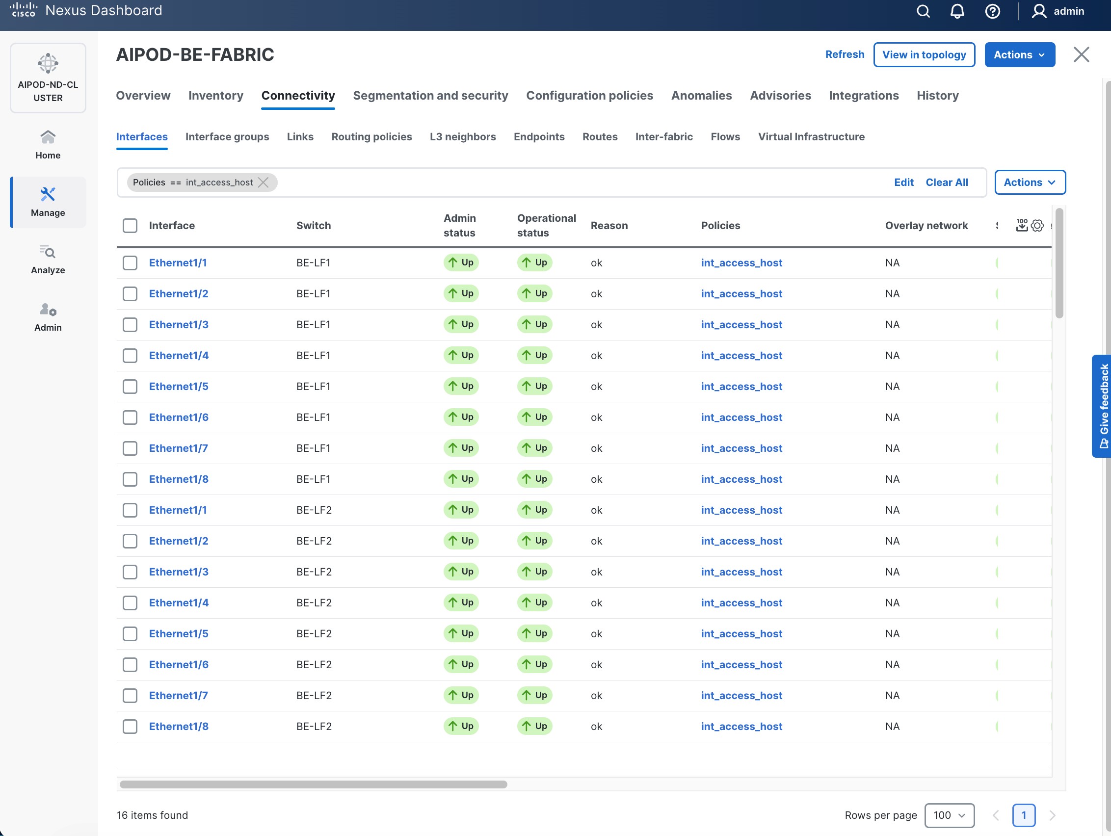
Procedure 2. Deploy L2 overlay network in the BE fabric for inter-node UCS connectivity
Step 1. Use a web browser to navigate to the Nexus Dashboard. Use the management IP of any node in the ND cluster. Log in using admin account.
Step 2. From the left navigation menu, go to Manage > Fabrics.
Step 3. Select the BE Fabric from the list and click the BE fabric name.
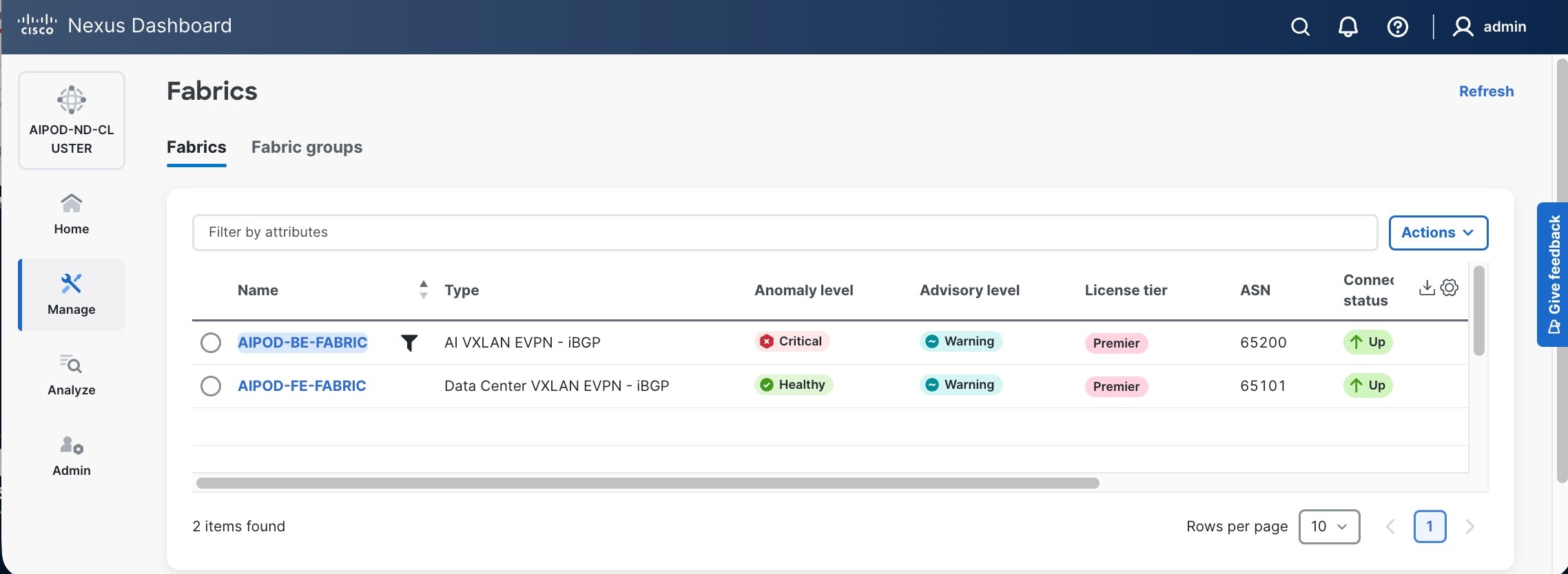
Step 4. Go to the Segmentation and Security > Networks tab. To deploy the BE network on UCS nodes, click the lower of the two Actions button and select Create from the drop-down list.
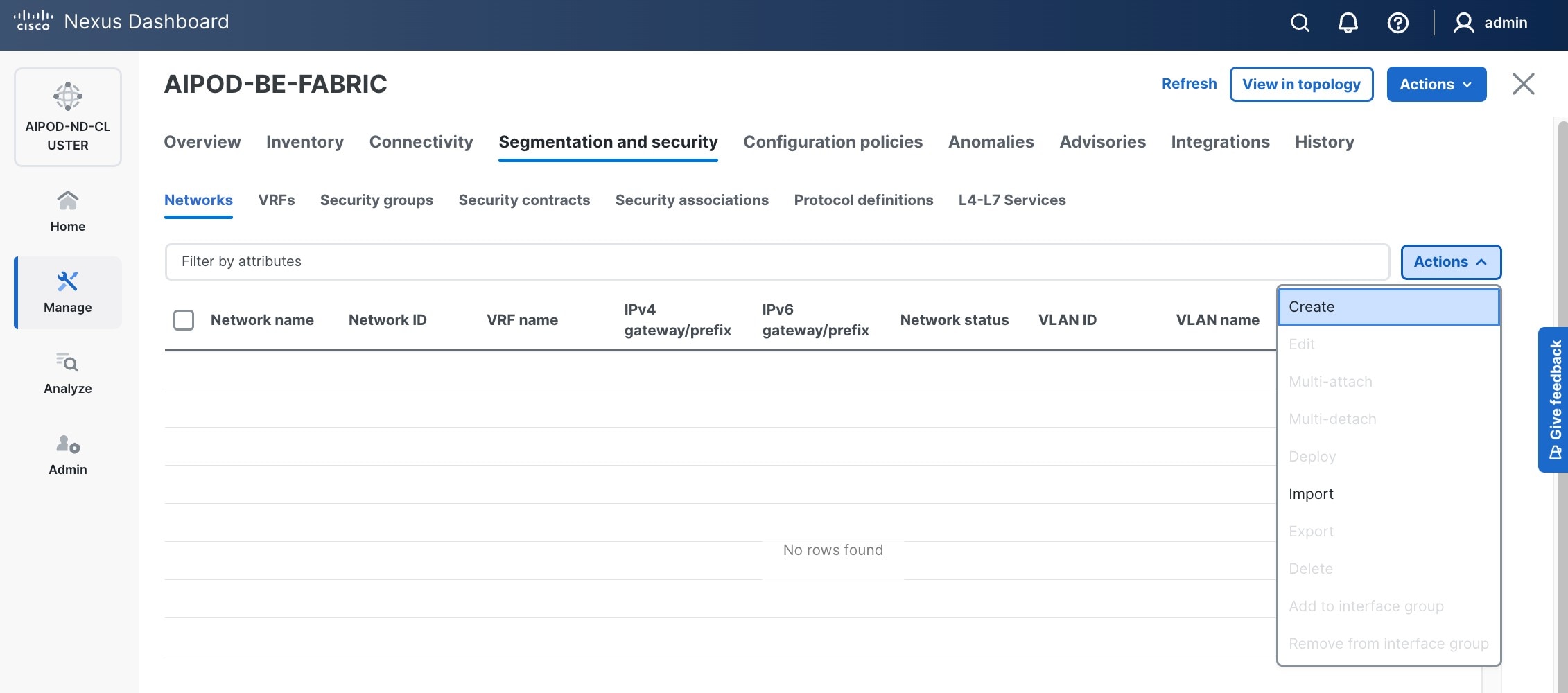
Step 5. In the Create Network window, specify the following:
a. Network name
b. Enable checkbox for Layer 2 only or VRF name if it is a Layer 3 network
c. Network ID (or use default)
d. VLAN ID (or use Propose VLAN for system to allocate).
e. For a Layer 3 network, if VRF hasn't been created already, you have an option from this window to also create a VRF (click Create VRF).
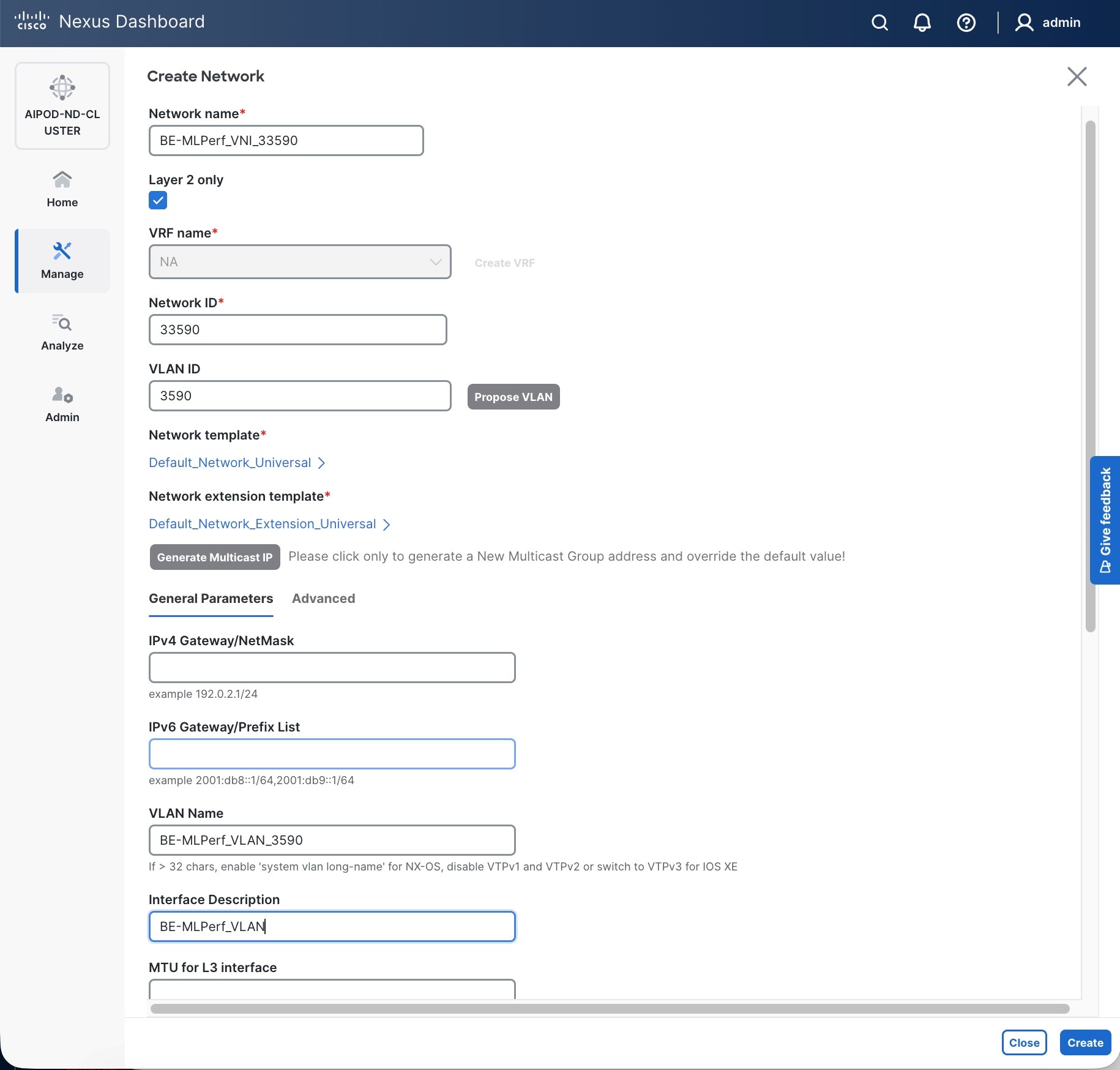
Step 6. Click Create to create the Layer 2 overlay network.
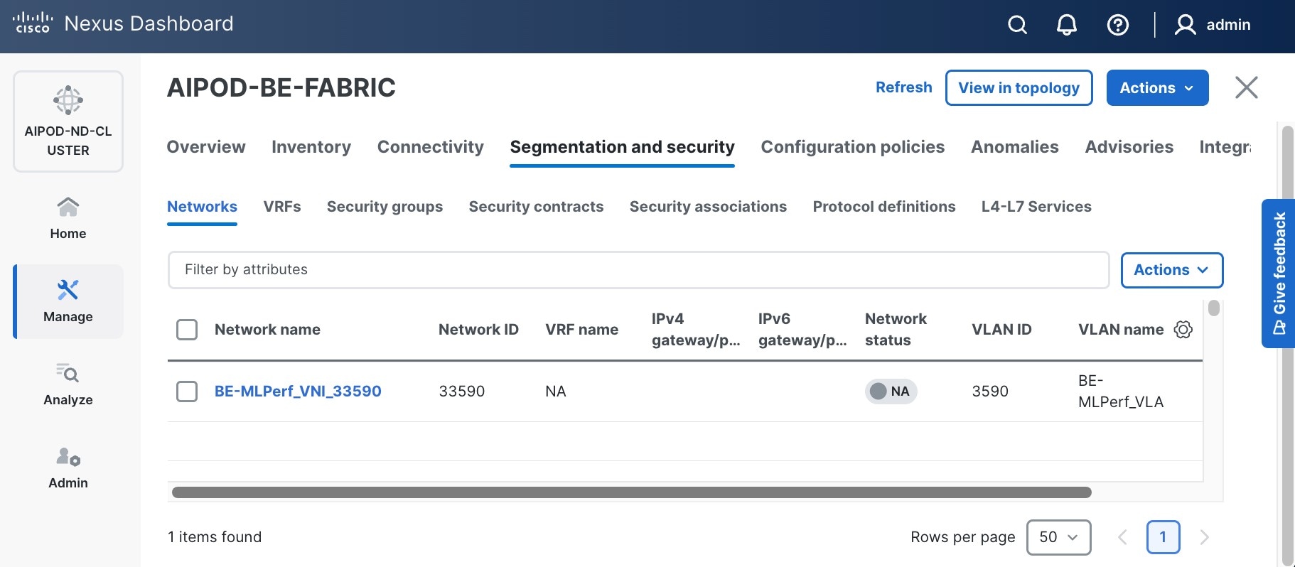
Step 7. Select newly created network and deploy it on both leaf pairs. Click the lower of the two Actions buttons and select Multi-attach from the list.
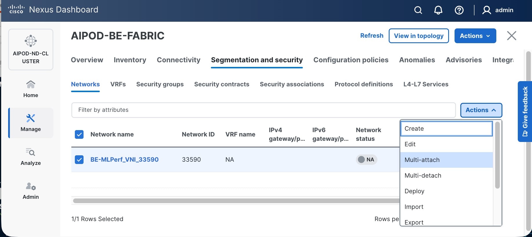
Step 8. Select both BE Leaf Switches.
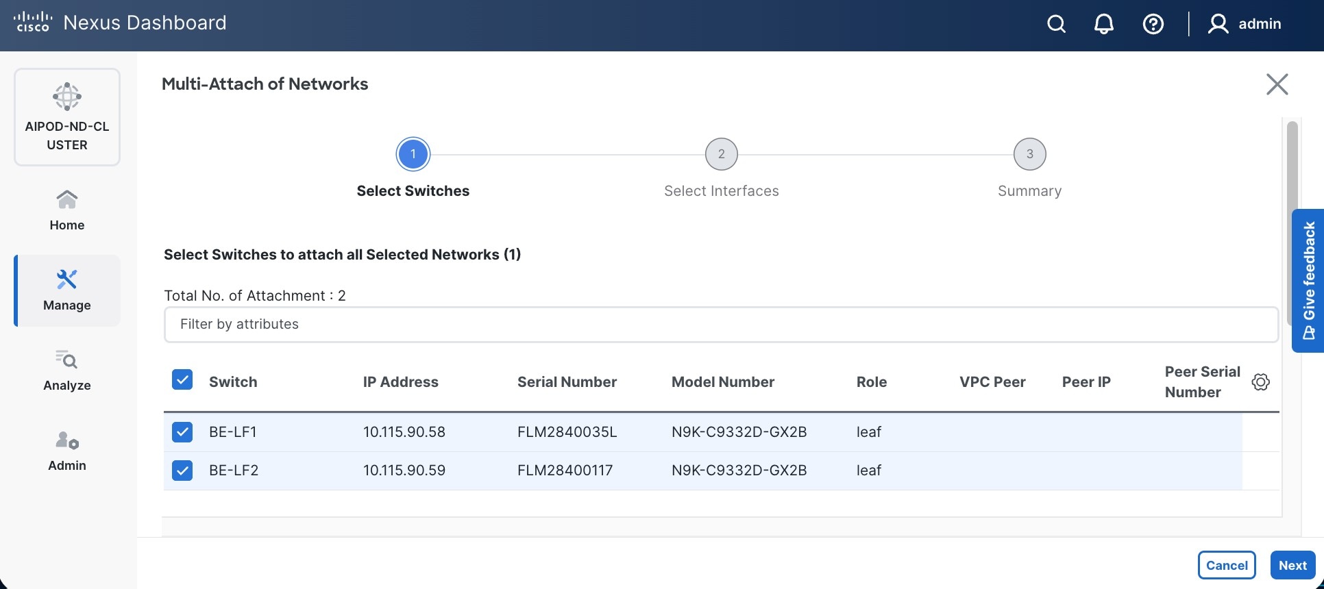
Step 9. Click Next. Select the row for the first switch and click Select Interfaces on the far right to select the interfaces going to the UCS C885A nodes on that switch.
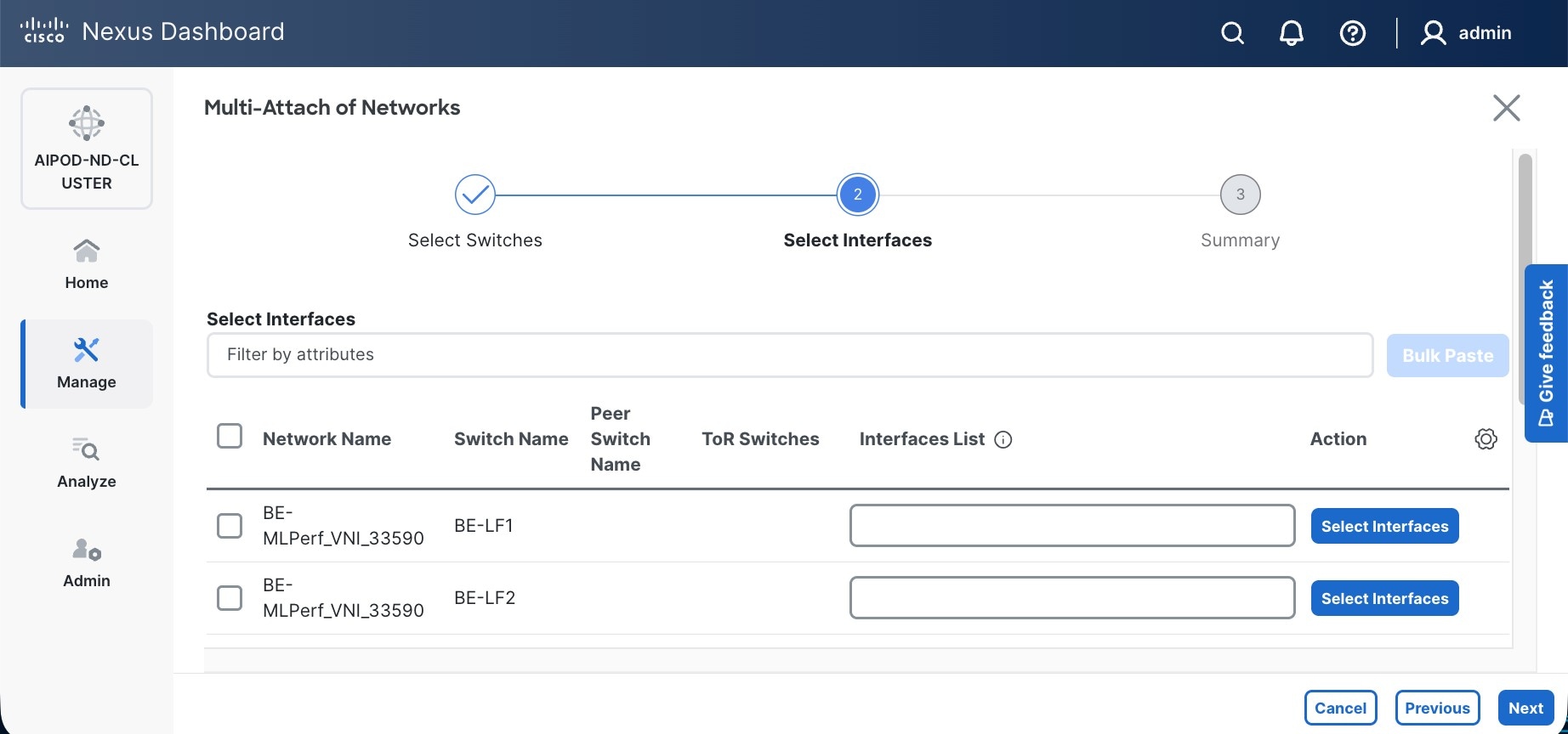
Step 10. Select all ports on the first switch that connect to UCS GPU nodes.
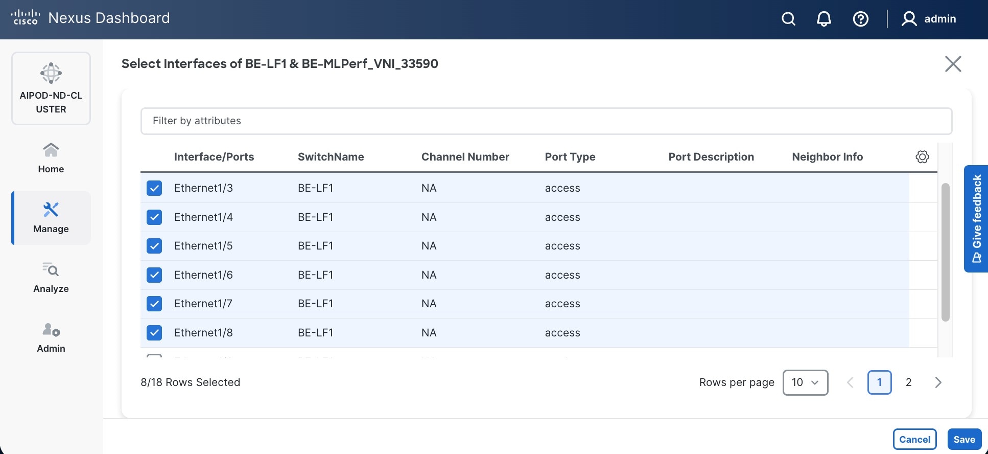
Step 11. Click Save.
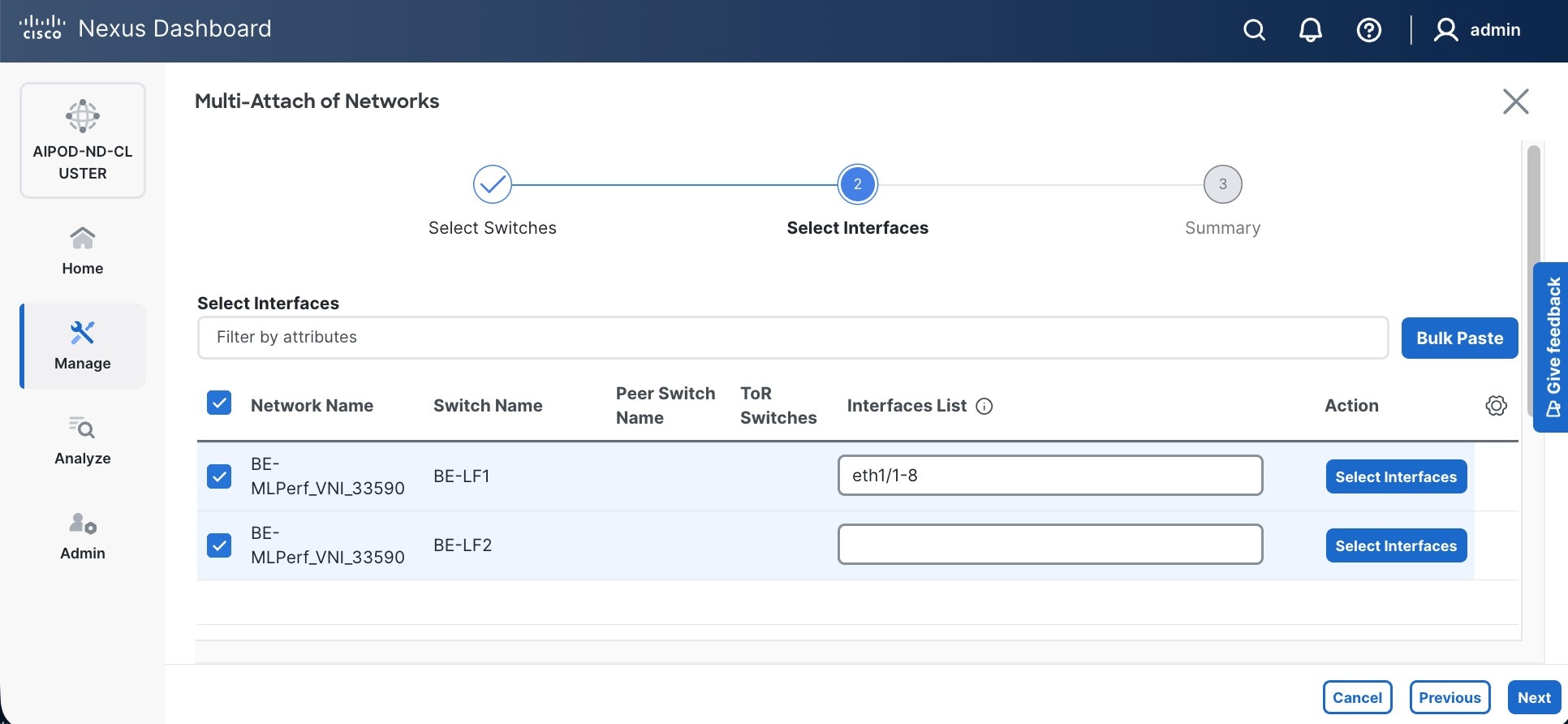
Step 12. Repeat this procedure for the second leaf switch to select the ports going to the UCS GPU nodes on that switch. (Repeat for any remaining leaf switches if you have more than two).
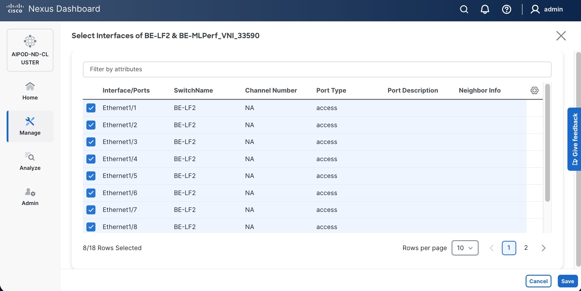
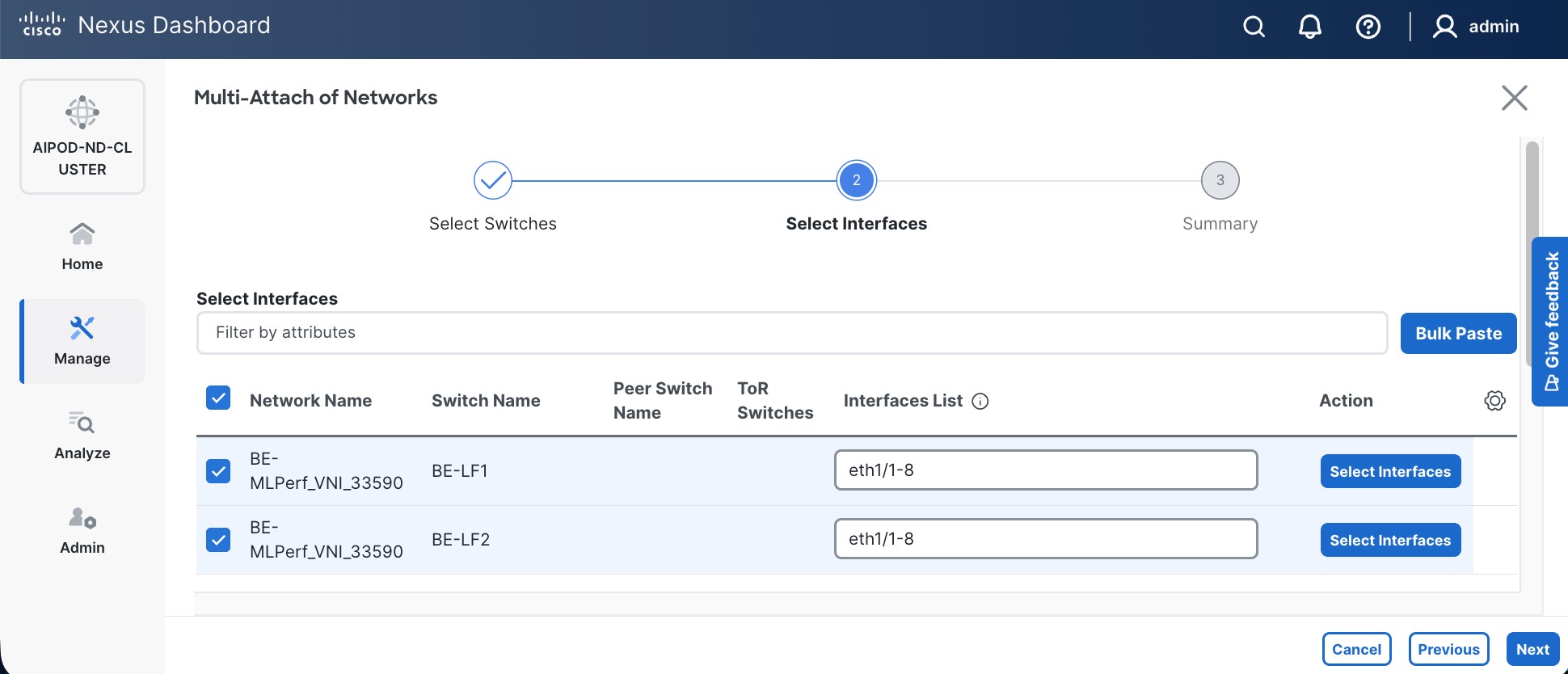
Step 13. Click Next.

Step 14. Click Save.
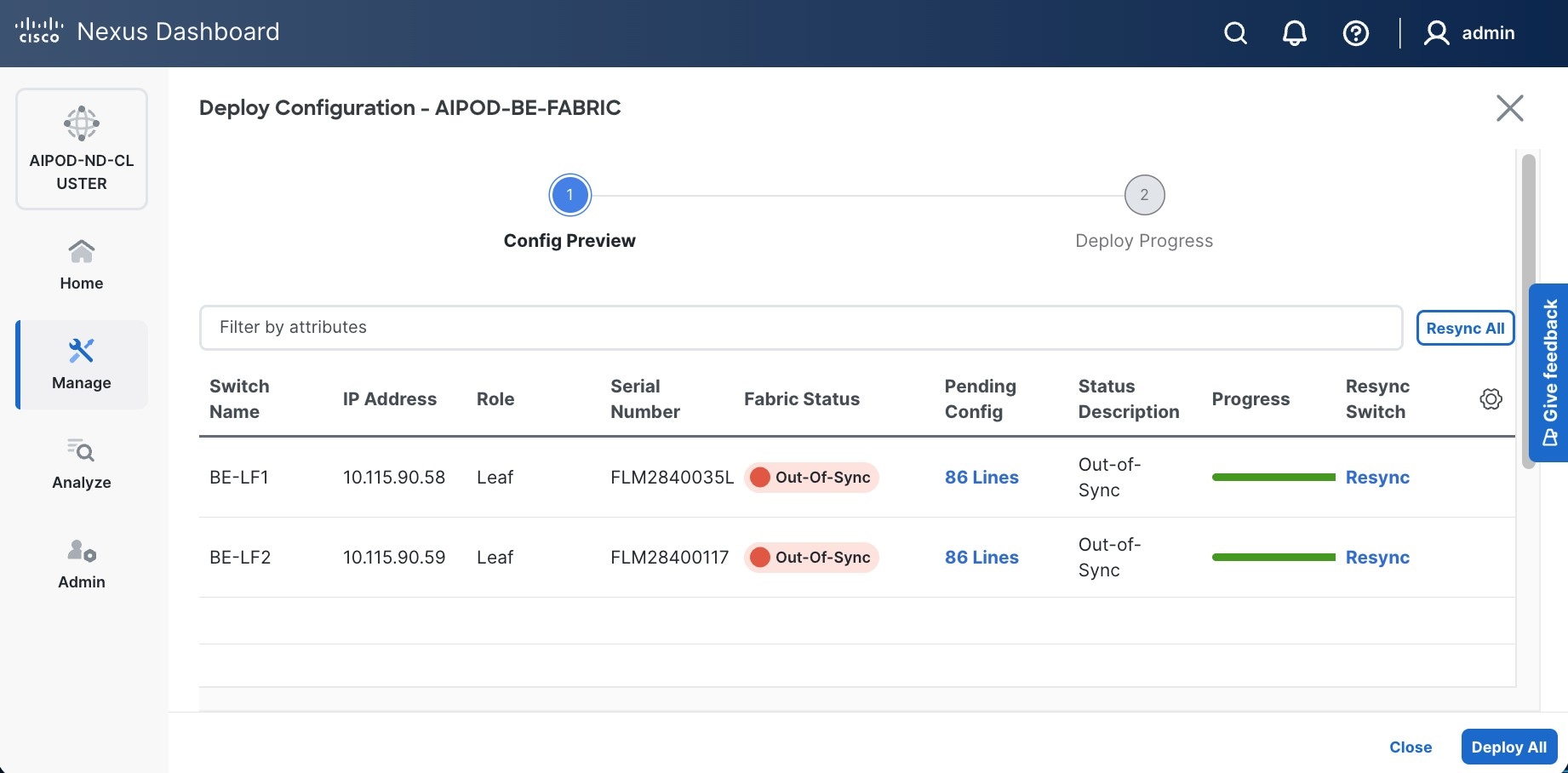
Note: Pending configuration being deployed on leaf switches is included at the end as a reference.
Step 15. Click Deploy All.
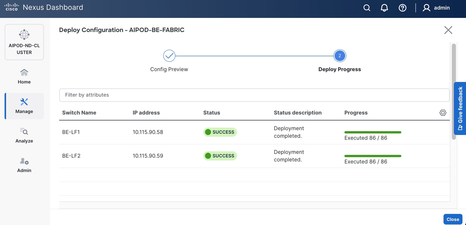
Step 16. Click Close.
Step 17. Click the network name and verify status is deployed.
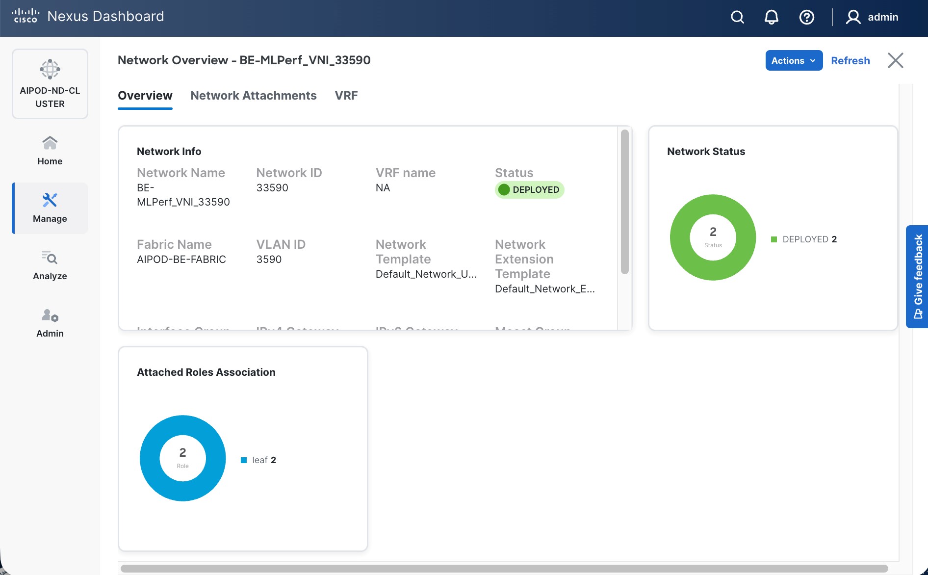
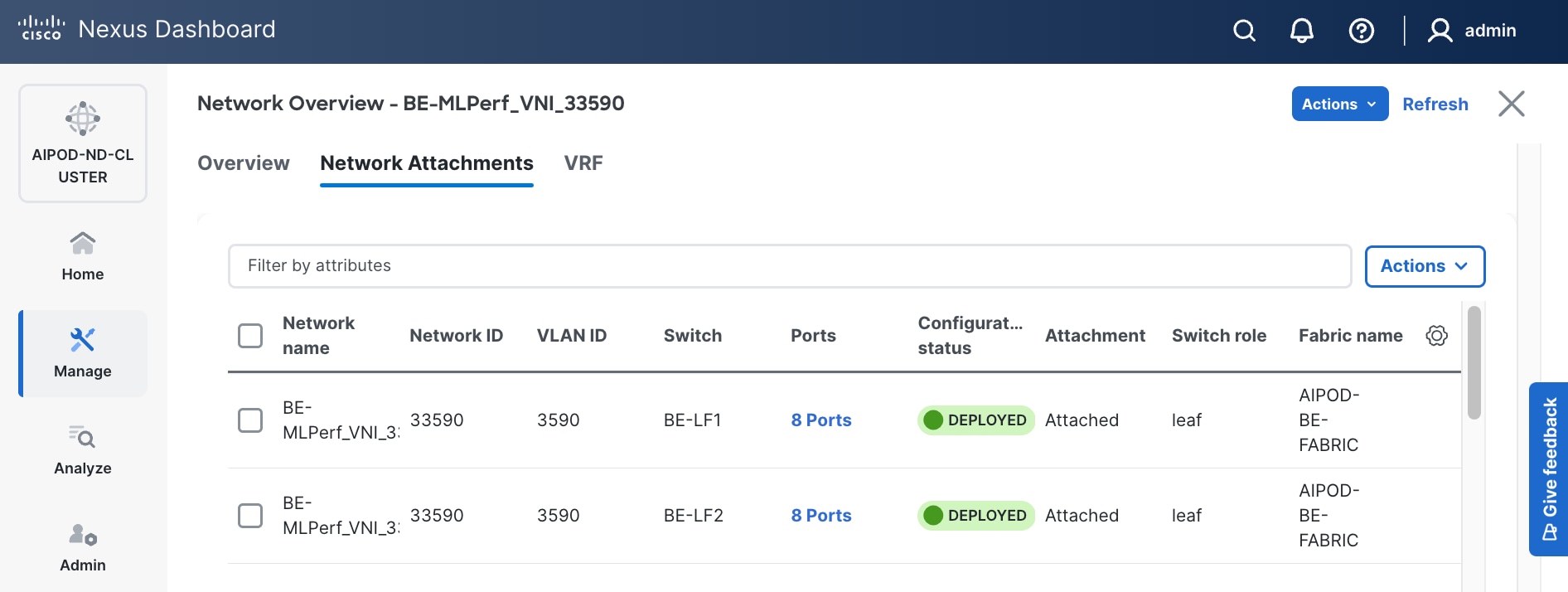
Step 18. Click X in the top right corner to close this window.
Step 19. Filter the newly deployed network 16 ports. Verify the status of all ports.
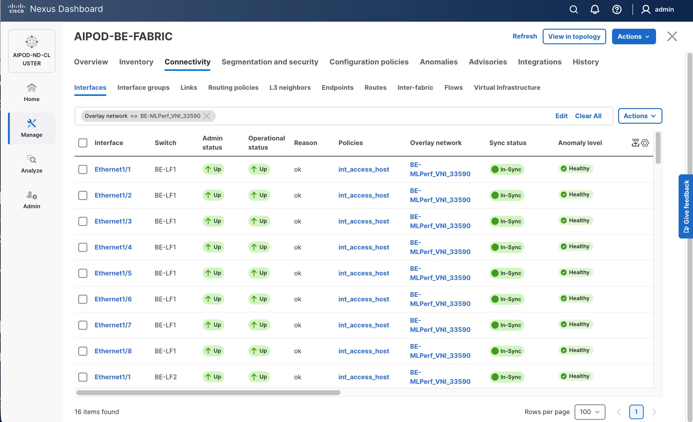
Step 20. Verify that ports on both switches are Up with an In-Sync status.
NetApp ONTAP Storage Configuration
This chapter contains the following:
● Configure NetApp ONTAP StorageConfigure NetApp ONTAP Storage
● Configure S3 access to the OpenShift TenantConfigure S3 access to the OpenShift Tenant
Configure NetApp ONTAP Storage
This section describes how to configure the NetApp ONTAP Storage for the OpenShift Tenant.
Procedure 1. Log into the Cluster
Step 1. Open an SSH connection to either the cluster IP or the host name.
Step 2. Log into the admin user with the password you provided earlier.
Procedure 2. Configure NetApp ONTAP Storage for the OpenShift Tenant
Note: By default, all network ports are included in a separate default broadcast domain. Network ports used for data services (for example, e3a, e2b, and so on) should be removed from their default broadcast domain and that broadcast domain should be deleted.
Step 1. Delete any Default-N automatically created broadcast domains:
network port broadcast-domain delete -broadcast-domain <Default-N> -ipspace Default
network port broadcast-domain show
Note: Delete the Default broadcast domains with Network ports (Default-1, Default-2, and so on). This does not include Cluster ports and management ports.
Step 2. Create an IPspace for the OpenShift tenant:
network ipspace create -ipspace AC01-OCP
Step 3. Create the OCP-MGMT and OCP-NFS broadcast domains with appropriate maximum transmission unit (MTU):
network port broadcast-domain create -broadcast-domain OCP-MGMT -mtu 1500 -ipspace AC01-OCP
network port broadcast-domain create -broadcast-domain OCP-NFS -mtu 9000 -ipspace AC01-OCP
network port vlan create -node rtp5-ac01-nas-n01 -vlan-name e3a-703
network port vlan create -node rtp5-ac01-nas-n01 -vlan-name e2b-703
network port vlan create -node rtp5-ac01-nas-n02 -vlan-name e3a-703
network port vlan create -node rtp5-ac01-nas-n02 -vlan-name e2b-703
network port broadcast-domain add-ports -ipspace AC01-OCP -broadcast-domain OCP-MGMT -ports rtp5-ac01-nas-n01:e3a-703,rtp5-ac01-nas-n01:e2b-703,rtp5-ac01-nas-n02:e3a-703, rtp5-ac01-nas-n02:e2b-703
Step 5. Create the OpenShift NFS VLAN ports and add them to the NFS broadcast domain:
network port vlan create -node rtp5-ac01-nas-n01 -vlan-name e3a-3051
network port vlan create -node rtp5-ac01-nas-n02 -vlan-name e3a-3051
network port broadcast-domain add-ports -ipspace AC01-OCP -broadcast-domain OCP-NFS -ports rtp5-ac01-nas-n01:e3a-3051,rtp5-ac01-nas-n01:e2b-3051,rtp5-ac01-nas-n02:e3a-3051,rtp5-ac01-nas-n02:e2b-3051
Step 6. Create the SVM (Storage Virtual Machine) in IPspace. Run the vserver create command:
vserver create -vserver rtp5-ac01-nas-tme-ucs885 -ipspace AC01-OCP
Note: The SVM must be created in the IPspace. An SVM cannot be moved into an IPspace later.
Step 7. Add the required data protocols to the SVM and remove the unused data protocols from the SVM:
vserver add-protocols -vserver rtp5-ac01-nas-tme-ucs885 -protocols nfs
vserver remove-protocols -vserver rtp5-ac01-nas-tme-ucs885 -protocols cifs,fcp, iscsi, nvme
Note: Make sure licenses are installed for all storage protocols used before creating the services.
Step 8. Add the two data aggregates to the OCP-SVM aggregate list and enable and run the NFS protocol in the SVM:
vserver modify -vserver rtp5-ac01-nas-tme-ucs885 -aggr-list AC01_NAS_01_SSD_1, AC01_NAS_02_SSD_1
set -privilege advanced
vserver nfs create -vserver rtp5-ac01-nas-tme-ucs885 -udp disabled -v3 enabled -v4.1 enabled -tcp-max-xfer-size 262144
set -privilege admin
Step 9. Create a Load-Sharing Mirror of the SVM Root Volume. Create a volume to be the load-sharing mirror of the infrastructure SVM root volume only on the node that does not have the Root Volume:
volume show -vserver rtp5-ac01-nas-tme-ucs885 # Identify the aggregate and node where the vserver root volume is located.
volume create -vserver rtp5-ac01-nas-tme-ucs885 -volume rtp5_ac01_nas_tme_ucs885_root_lsm01 -aggregate AC01_NAS_0<x>_SSD_1 -size 1GB -type DP # Create the mirror volume on the other node
Step 10. Create the 15min interval job schedule:
job schedule interval create -name 15min -minutes 15
Step 11. Create the mirroring relationship:
snapmirror create -source-path rtp5-ac01-nas-tme-ucs885: rtp5_ac01_nas_tme_ucs885_rootvol -destination-path rtp5_ac01_nas_tme_ucs885_rootvol_lsm01 -type LS -schedule 15min
Step 12. Initialize and verify the mirroring relationship:
snapmirror initialize-ls-set -source-path rtp5-ac01-nas-tme-ucs885:rtp5_ac01_nas_tme_ucs885_rootvol
snapmirror show -vserver rtp5-ac01-nas-tme-ucs885
Progress
Source Destination Mirror Relationship Total Last
Path Type Path State Status Progress Healthy Updated
----------- ---- ------------ ------- -------------- --------- ------- --------
rtp5-ac01-nas://rtp5-ac01-nas-tme-ucs885/rtp5_ac01_nas_tme_ucs885_rootvol
LS rtp5-ac01-nas://rtp5-ac01-nas-tme-ucs885/rtp5_ac01_nas_tme_ucs885_rootvol_lsm01
Snapmirrored
Idle - true -
Step 13. To create the login banner for the SVM, run the following command:
security login banner modify -vserver rtp5-ac01-nas-tme-ucs885 -message "This AI POD SVM is reserved for authorized users only!"
Step 14. Create a new rule for the SVM NFS subnet in the default export policy and assign the policy to the SVM’s root volume:
vserver export-policy rule create -vserver rtp5-ac01-nas-tme-ucs885 -policyname default -ruleindex 1 -protocol nfs -clientmatch 192.168.51.0/24 -rorule sys -rwrule sys -superuser sys -allow-suid true
volume modify –vserver rtp5-ac01-nas-tme-ucs885 –volume rtp5_ac01_nas_tme_ucs885_root –policy default
Step 15. Create a service policy for the S3 object store:
Note: You need to switch to privileged mode.
set -privilege advanced
network interface service-policy create -vserver rtp5-ac01-nas-tme-ucs885 -policy aipod-data-s3 -services data-s3-server,data-core -allowed-addresses 0.0.0.0/0
set -privilege admin #Switch back to admin mode
Step 16. Create and enable the audit log in the SVM:
volume create -vserver rtp5-ac01-nas-tme-ucs885 -volume audit_log -aggregate AC01_NAS_01_SSD_1 -size 50GB -state online -policy default -junction-path /audit_log -space-guarantee none -percent-snapshot-space 0
snapmirror update-ls-set -source-path rtp5-ac01-nas-tme-ucs885:rtp5_ac01_nas_tme_ucs885_rootvol
vserver audit create -vserver rtp5-ac01-nas-tme-ucs885 -destination /audit_log
vserver audit enable -vserver rtp5-ac01-nas-tme-ucs885
Step 17. Run the following commands to create general NFS Logical Interfaces (LIFs):
network interface create -vserver rtp5-ac01-nas-tme-ucs885 -lif rtp5-ac01-nas-tme-ucs885-lif1 -service-policy default-data-files -home-node rtp5-ac01-nas-n01 -home-port e2b-3051 -address 192.168.51.121 -netmask 255.255.255.0 -status-admin up -failover-policy broadcast-domain-wide -auto-revert true
network interface create -vserver rtp5-ac01-nas-tme-ucs885 -lif rtp5-ac01-nas-tme-ucs885-lif2 -service-policy default-data-files -home-node rtp5-ac01-nas-n02 -home-port e2b-3051 -address 192.168.51.122 -netmask 255.255.255.0 -status-admin up -failover-policy broadcast-domain-wide -auto-revert true
Step 18. Run the following commands to create ONTAP S3 LIFs:
network interface create -vserver rtp5-ac01-nas-tme-ucs885 -lif rtp5-ac01-nas-tme-ucs885-s3-1 -service-policy aipod-data-s3 -home-node rtp5-ac01-nas-n01 -home-port e2b-703 -address 10.115.90.117 -netmask 255.255.255.192 -status-admin up -failover-policy broadcast-domain-wide -auto-revert true
network interface create -vserver rtp5-ac01-nas-tme-ucs885 -lif rtp5-ac01-nas-tme-ucs885-s3-2 -service-policy aipod-data-s3 -home-node rtp5-ac01-nas-n02 -home-port e2b-703 -address 10.115.90.118 -netmask 255.255.255.192 -status-admin up -failover-policy broadcast-domain-wide -auto-revert true
network interface create -vserver rtp5-ac01-nas-tme-ucs885 -lif rtp5-ac01-nas-tme-ucs885-s3-3 -service-policy aipod-data-s3 -home-node rtp5-ac01-nas-n01 -home-port e3a-703 -address 10.115.90.119 -netmask 255.255.255.192 -status-admin up -failover-policy broadcast-domain-wide -auto-revert true
network interface create -vserver rtp5-ac01-nas-tme-ucs885 -lif rtp5-ac01-nas-tme-ucs885-s3-4 -service-policy aipod-data-s3 -home-node rtp5-ac01-nas-n02 -home-port e3a-703 -address 10.115.90.120 -netmask 255.255.255.192 -status-admin up -failover-policy broadcast-domain-wide -auto-revert true
Step 19. Run the following command to create the SVM-MGMT LIF:
network interface create -vserver rtp5-ac01-nas-tme-ucs885 -lif rtp5-ac01-nas-tme-ucs885-mgmt -service-policy default-management -home-node rtp5-ac01-nas-n01 -home-port e2b-703 -address 10.115.90.121 -netmask 255.255.255.192 -status-admin up -failover-policy broadcast-domain-wide -auto-revert true
Step 20. Run the following command to verify LIFs:
network interface show -vserver rtp5-ac01-nas-tme-ucs885
Logical Status Network Current Current Is
Vserver Interface Admin/Oper Address/Mask Node Port Home
----------- ---------- ---------- ------------------ ------------- ------- ----
rtp5-ac01-nas-tme-ucs885
rtp5-ac01-nas-tme-ucs885-lif1 up/up 192.168.51.121/24 rtp5-ac01-nas-n01 e2b-3051
true
rtp5-ac01-nas-tme-ucs885-lif2 up/up 192.168.51.122/24 rtp5-ac01-nas-n02 e2b-3051
true
rtp5-ac01-nas-tme-ucs885-lif3 up/up 192.168.51.123/24 rtp5-ac01-nas-n01 e3a-3051
true
rtp5-ac01-nas-tme-ucs885-lif4 up/up 192.168.51.124/24 rtp5-ac01-nas-n02 e3a-3051
true
rtp5-ac01-nas-tme-ucs885-mgmt up/up 10.115.90.121/26 rtp5-ac01-nas-n01 e2b-703
true
rtp5-ac01-nas-tme-ucs885-s3-1 up/up 192.168.90.117/24 rtp5-ac01-nas-n01 e2b-703
rtp5-ac01-nas-tme-ucs885-s3-2 up/up 192.168.90.118/24 rtp5-ac01-nas-n02 e2b-703
true
rtp5-ac01-nas-tme-ucs885-s3-3 up/up 192.168.90.119/24 rtp5-ac01-nas-n01 e3a-703
true
rtp5-ac01-nas-tme-ucs885-s3-4 up/up 192.168.90.120/24 rtp5-ac01-nas-n02 e3a-703
true
9 entries were displayed.
Step 21. Create a default route that enables the SVM management interface to reach the outside world:
network route create -vserver rtp5-ac01-nas-tme-ucs885 -destination 0.0.0.0/0 -gateway 10.115.90.126
Step 22. Set a password for the SVM vsadmin user and unlock the user:
security login password -username vsadmin -vserver rtp5-ac01-nas-tme-ucs885
Enter a new password:
Enter it again:
security login unlock -username vsadmin -vserver rtp5-ac01-nas-tme-ucs885
Step 23. Add the OpenShift DNS servers to the SVM:
dns create -vserver rtp5-ac01-nas-tme-ucs885 -domains ocp-c885.aipod.local -name-servers 10.115.90.123,10.115.90.124
Configure S3 access to the OpenShift Tenant
Procedure 1. Enable S3 on the storage VM
Step 1. In NetApp System Manager, click Storage > Storage VMs, select the storage VM, click Settings, and then click the pencil icon under S3.
Step 2. Enter the S3 server name. Make sure to enter the S3 server name as a Fully Qualified Domain Name (FQDN).
Step 3. TLS is enabled by default (port 443). You can enable HTTP if required.
Step 4. Select the certificate type. Whether you select system-generated certificate or external-CA signed certificate, it will be required for client access.
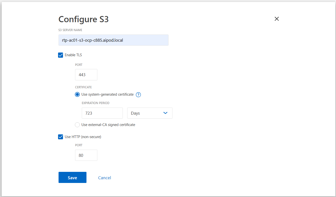
Step 5. Click Save.
The ONTAP S3 object store server is now configured as shown in the following figure. There are two users created by default:
1. root user with UID 0 – no access key or secret key is generated for this user
2. sm_s3_user – both access and secret keys are generated for this user. Save access keys and secret keys for future use.
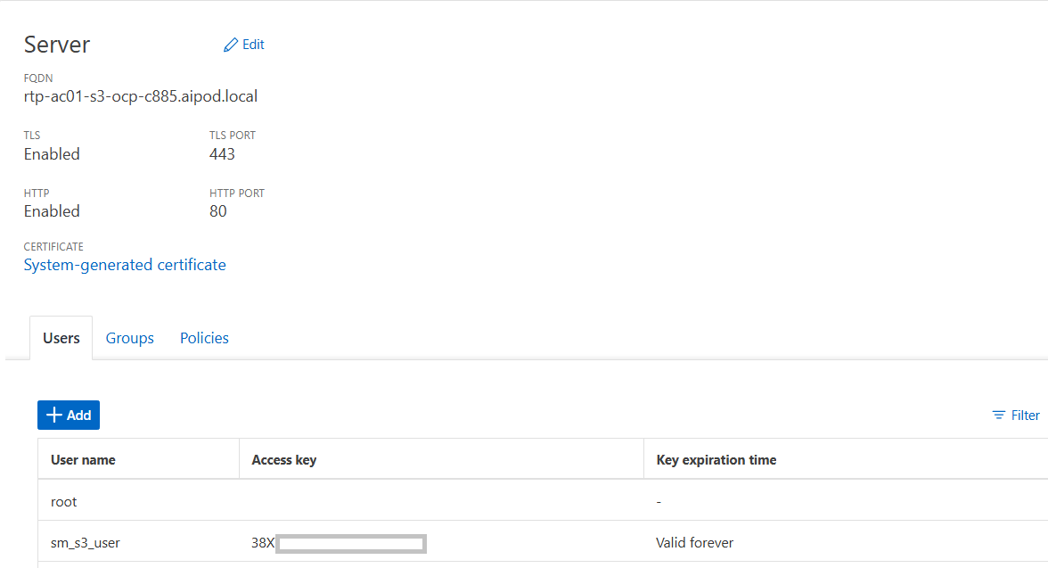
Note: The ONTAP administrator must run the object-store-server users regenerate-keys command to set the access key and secret key for the root user. As a NetApp best practice, do not use this root user. Any client application that uses the access key or secret key of the root user has full access to all buckets and objects in the object store.
Step 6. You can choose to utilize the default user (sm_s3_user) or create a custom ONTAP S3 user:
● Click StorageStorage > StorageStorage VMsVMs. Select the storage VM to which you need to add a user, select SettingsSettings and then click the pencilpencil iconicon under S3.
● To add a user, click UsersUsers > AddAdd.
● Enter a name for the user. Click SaveSave.
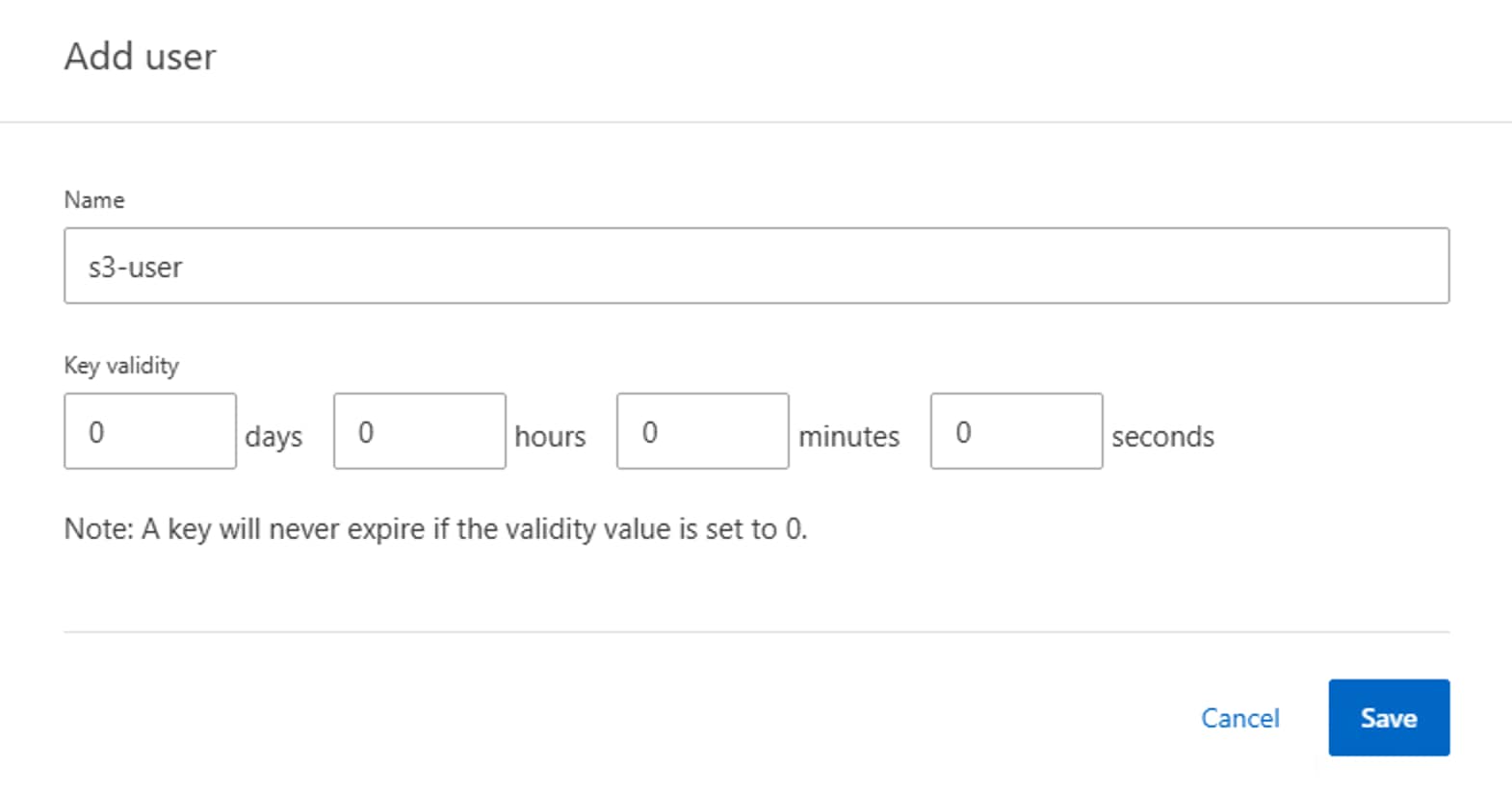
The user is created, and an access key and a secret key are generated for the user.
● Download or save the access key and secret key. These will be required for access from S3 clients.
Note: Beginning with ONTAP 9.14.1, you can specify the retention period of the access keys that get created for the user. You can specify the retention period in days, hours, minutes, or seconds, after which the keys automatically expire. By default, the value is set to 0 that indicates that the key is indefinitely valid.
Procedure 2. Create ONTAP S3 user group to control access to buckets
Step 1. Click Storage > Storage VMs. Select the storage VM to which you need to add a group, select Settings and then click the pencil icon under S3.
Step 2. To add a group, select Groups, then click Add.
Step 3. Enter a group name and select from a list of users.
Step 4. You can select an existing group policy or add one now, or you can add a policy later. In this configuration, we have used an existing policy (FullAccess).
Step 5. Click Save.
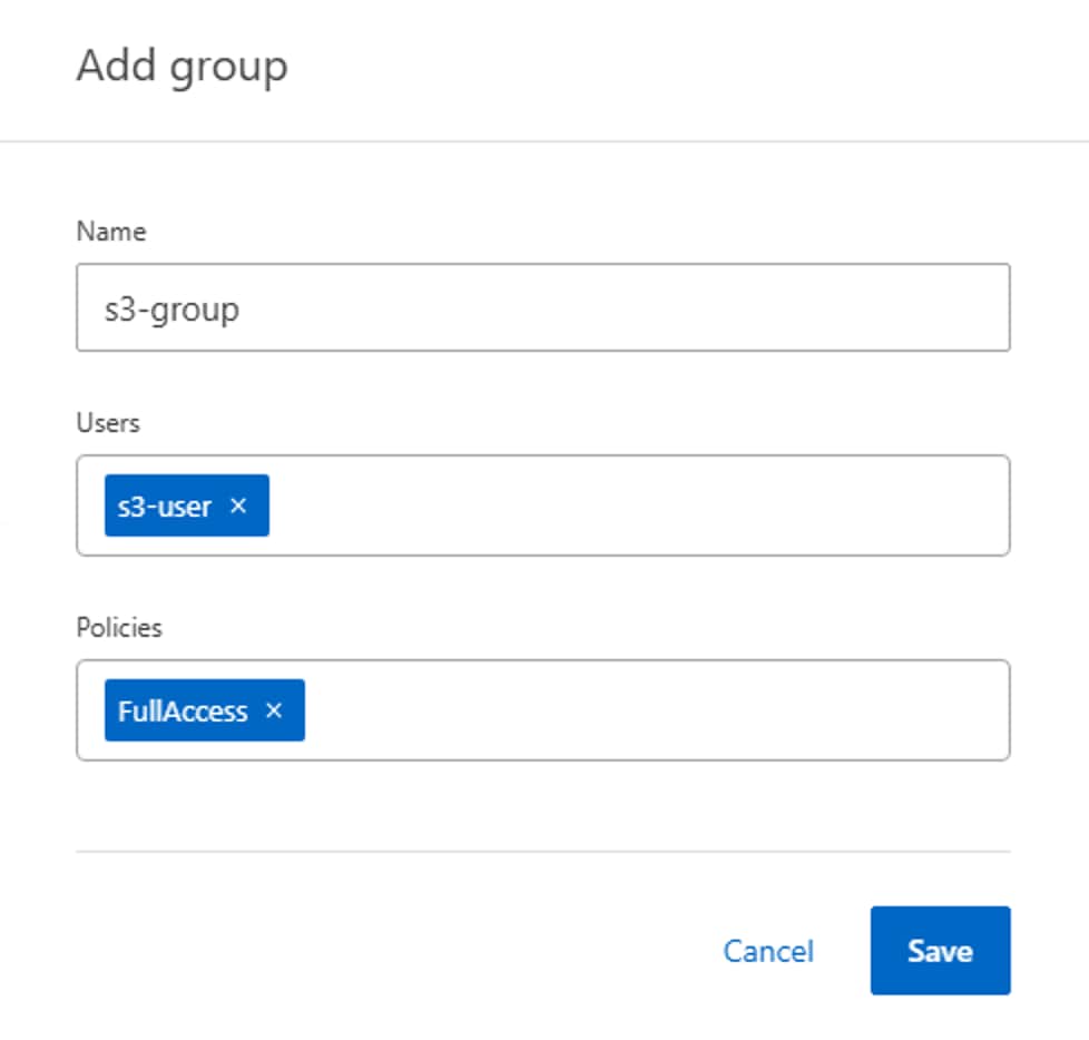
Procedure 3. Create an ONTAP S3 bucket
Step 1. Click Storage > Buckets, then click Add.
Step 2. Enter a name for the bucket, select the storage VM, and enter the size.
a. If you click Save at this point, a bucket is created with these default settings:
i. No users are granted access to the bucket unless any group policies are already in effect.
ii. A Quality of Service (performance) level that is the highest available for your system.
b. Click Save to create a bucket.
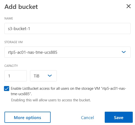
Step 3. On the bucket, click the three dots and select Edit. Under Permissions section, click Add to add relevant permissions for accessing the bucket. Specify the following parameters:
a. Principal: the user or group to whom access is granted. Here, we selected “s3-group”.
b. Effect: allows or denies access to a user or group. Allow is selected here for “s3-group”.
c. Actions: permissible actions in the bucket for a given user or group. Select as required for validation.
d. Resources: paths and names of objects within the bucket for which access is granted or denied. The defaults bucketname and bucketname/* grant access to all objects in the bucket. In this solution, we used default values for resources (s3-bucket1,s3-bucket1/*)
e. Conditions (optional): expressions that are evaluated when access is attempted. For example, you can specify a list of IP addresses for which access will be allowed or denied. In this case, the field value was empty as no conditions were specified.
Step 4. Click Save.
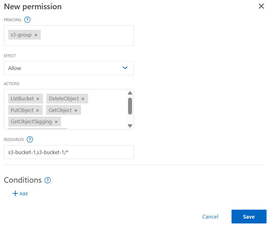
Step 5. Click Save to create the ONTAP S3 bucket.
Step 6. ONTAP S3 is successfully created as shown in the following figure. Navigate to Storage > Buckets, select the bucket (s3-bucket1) and click Overview tab to see detailed information about the bucket.
Step 7. On S3 client applications (whether ONTAP S3 or an external third-party application), you can verify access to the newly created S3 bucket. In this solution, we used the S3 Browser application to access the bucket as shown below:
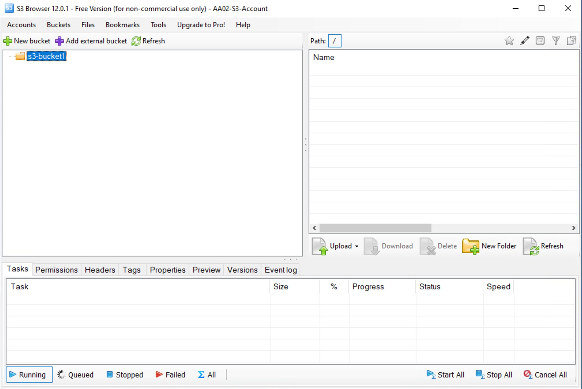
Note: In S3 Browser application, new account needs to be created first by providing S3 user access key and secret key, and REST endpoint (http://<s3-lif-ip>:80). Once the account is successfully added, the S3 buckets are fetched automatically as shown above.
This chapter contains the following:
● Set up Cisco Intersight Resource GroupSet up Cisco Intersight Resource Group
This section details the configuration of the Cisco UCS C885A 8-GPU servers. These servers can currently be monitored by Cisco Intersight, but policy-based configuration will come in the future. The following sections go through updating server firmware and configuring the servers for an AI training environment. This procedure will need to be followed for each C885A server. The server should be installed according to Cisco UCS C885A M8 Server Installation and Service Guide and cabled according to Table 4. Set up the Cisco BMC with either a static or DHCP IP address.
Set up Cisco Intersight Resource Group
Procedure 1. Initial C885A Setup
In this procedure, the Cisco UCS C885A is initially setup.
Step 1. Using a web browser, connect to https://<BMC IP>. The default user id is root, and the default password is “password.” The first time you connect, you will be asked to set a strong password.
Step 2. Once connected, click Select Timezone. Use the drop-down list to select the current Timezone. Click Confirm.
Step 3. Go to Settings > Network. Ensure that all necessary network information is in place, including DNS servers and DNS Search domain.
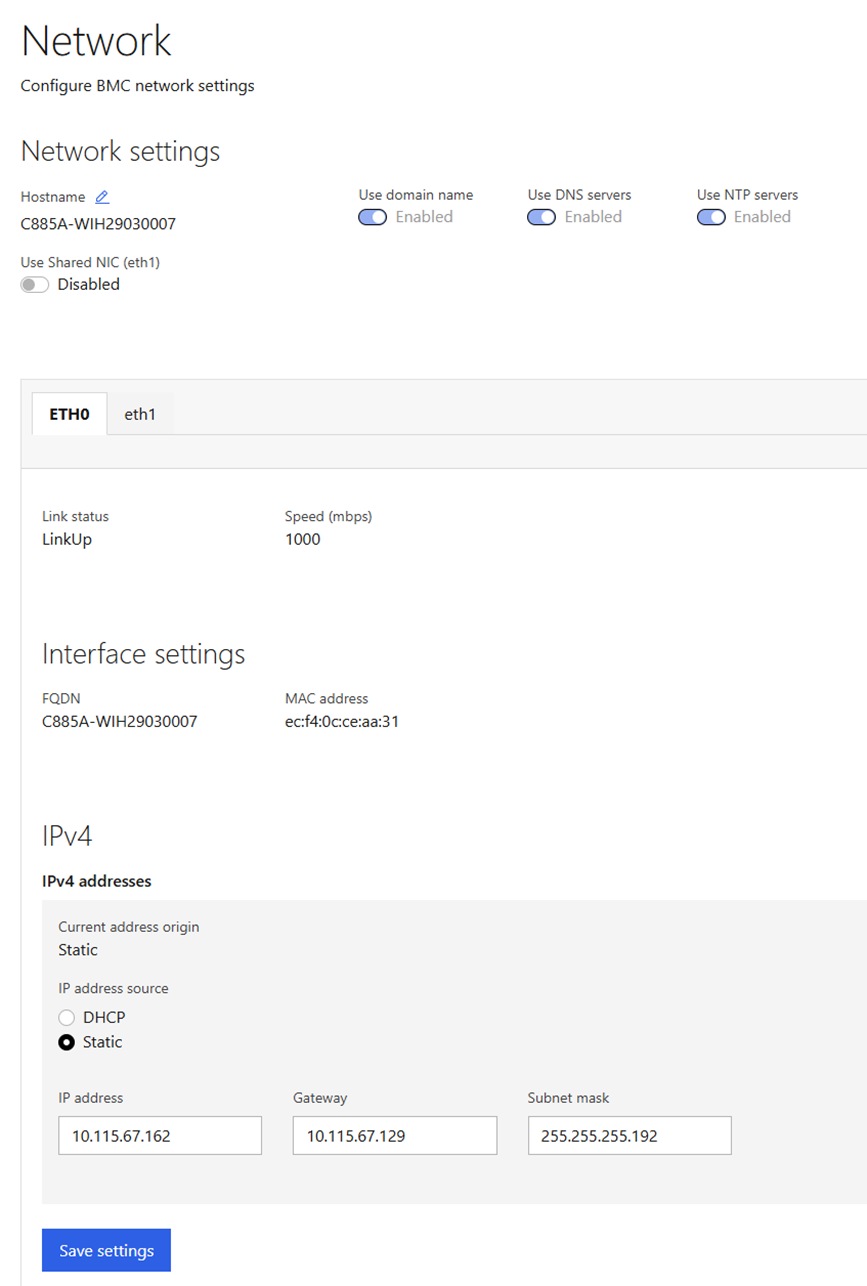
Step 4. Go to Settings > Date and time. Enter up to three NTP servers and click Save settings. After these settings have been saved return to this screen and verify the correct time.
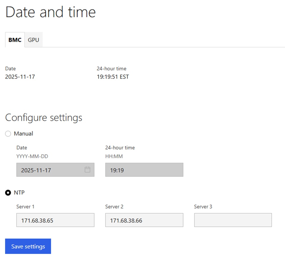
Step 5. Go to Security and access > Policies. Enable both BMC shell (via SSH) and Network IPMI (out-of-band IPMI).
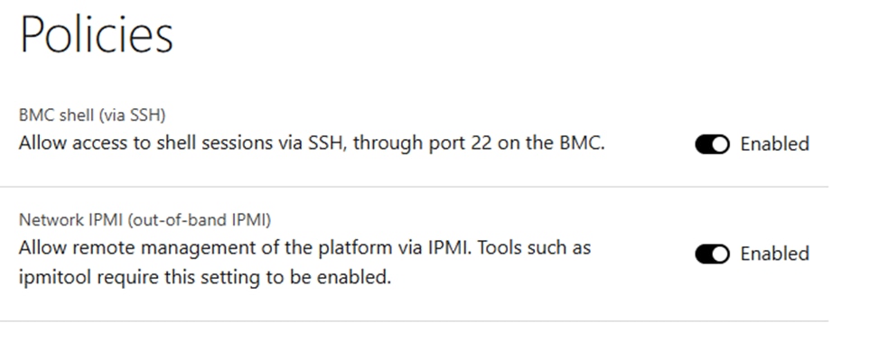
Procedure 2. Configure C885A BIOS Settings
Configure the C885A BIOS Settings to work with AI applications.
Step 1. Go to Configure > Configure BIOS > I/O. Configure settings as shown without selecting Reboot Host Immediately. If any changes are made, click Save.
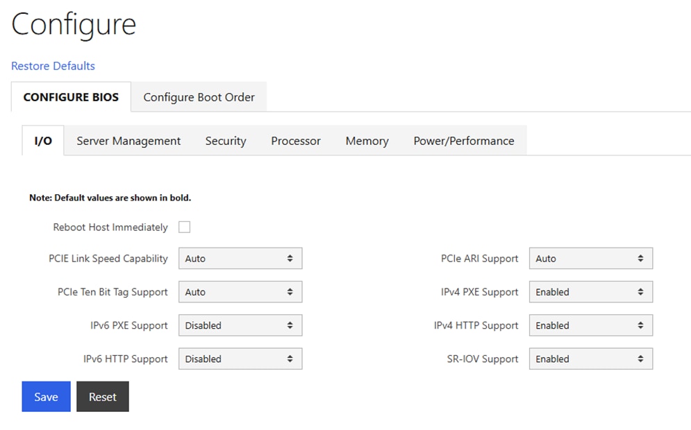
Step 2. Go to Configure > Configure BIOS > Server Management. Configure settings as shown without selecting Reboot Host Immediately. If any changes are made, click Save.
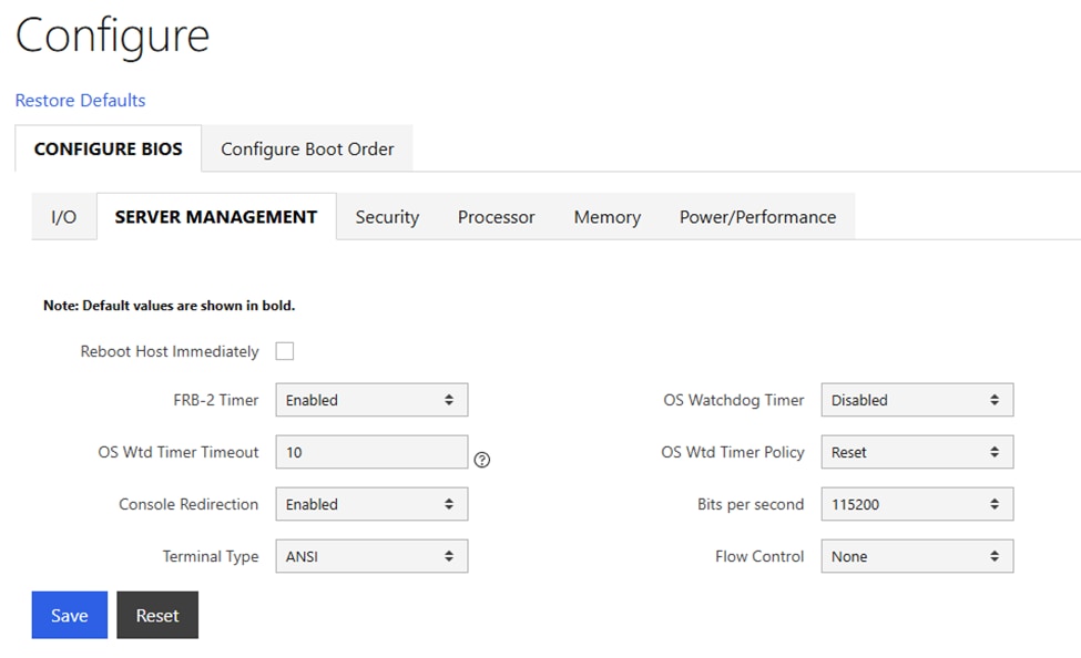
Step 3. Go to Configure > Configure BIOS > Security. Configure settings as shown without selecting Reboot Host Immediately. If any changes are made, click Save.
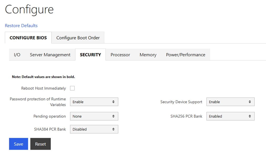
Step 4. Go to Configure > Configure BIOS > Processor. Configure settings as shown without selecting Reboot Host Immediately. If any changes are made, click Save.
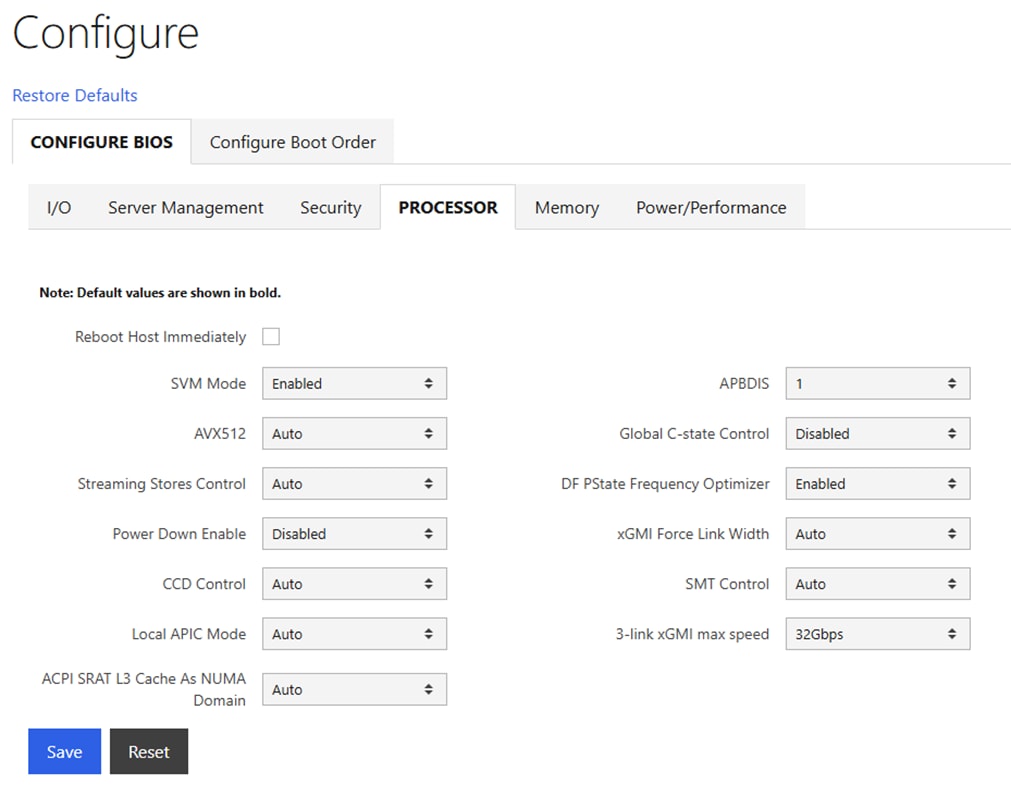
Step 5. Go to Configure > Configure BIOS > Memory. Configure settings as shown without selecting Reboot Host Immediately. If any changes are made, click Save. Note that IOMMU should be Enabled.
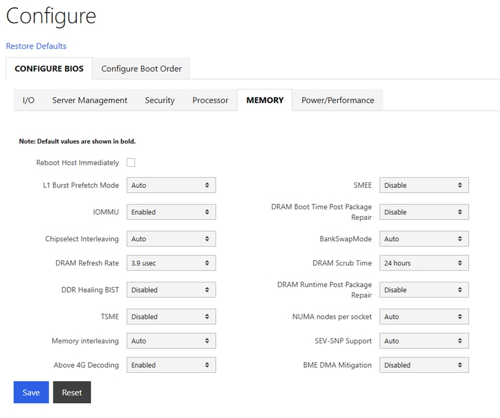
Step 6. Go to Configure > Configure BIOS > Power/Performance. Configure settings as shown and select Reboot Host Immediately. Click Save.
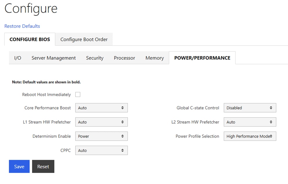
Procedure 3. Disable BlueField Internal CPU (DPU)
If you have BlueField-3 (BF-3) NIC Cards in your frontend or N-S network, it is often desirable to configure the two 200G or 100G ports in an LACP bond. It has been determined that if the DPUs in the BF-3 NICs are enabled, the LACP PDUs to the switches are blocked. It is necessary to disable the DPUs for the LACP vPC port-channels on the Cisco Nexus switches to function properly. This will need to be done on all N-S BF-3 NICs on all the Cisco UCS C885As.
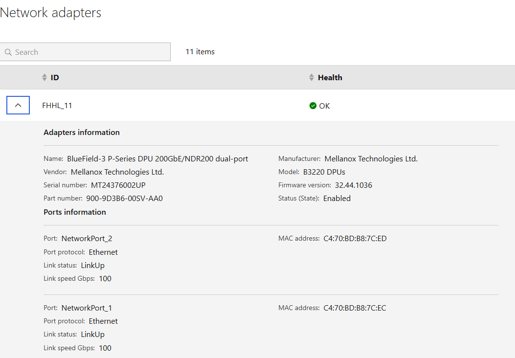
Step 2. Select Operations > KVM and click Launch KVM. The KVM will open in a separate window. On Windows, the KVM will open in full screen but can be sized down.
Step 3. From the Host Power drop-down list, select Power Cycle and click Confirm.
Step 4. When the server comes back up and you see Press <DEL> or <ESC> to enter setup, press either of those keys. You should then see an Entering Setup message.
Step 5. Use the right arrow key to move to the Advanced tab and then Arrow down until you find an Nvidia Network Adapter with a MAC address that matches what was queried in Step 1. When the adapter is highlighted, press Enter to open it. Arrow down to BlueField Internal Cpu Configuration and press Enter to open it. Arrow down to the field to the right of Internal Cpu Offload Engine and use the arrow keys and Enter key to set the field to Disabled. Hit the ESC key twice to back out to the device selection page. Repeat this process for all BF-3 ports connected to the frontend network. Press F4 to Save and Exit and click Yes to verify. The server will reboot with the DPUs
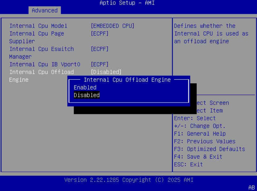
Procedure 4. Claiming Cisco UCS C885A to Intersight
Cisco UCS C885A servers can be claimed into Cisco Intersight to provide detailed hardware and monitoring information. You can also access the BMC interface and the KVM interface from Intersight. To claim a C885A server into Intersight, complete the following steps.
Step 1. In the Cisco UCS C885A BMC interface, select Device connector on the left. At the same time, in Cisco Intersight in the account where you want to claim the C885A servers, select System > Targets. Click Claim a New Target and then select Cisco UCS Server (Standalone). Click Start. Select all resource groups you would like to place the server in. Copy and paste the Device ID and Claim Code from the C885A Device connector page and click Claim. After the target is claimed to Intersight, the status will update on the C885A Device connector page.
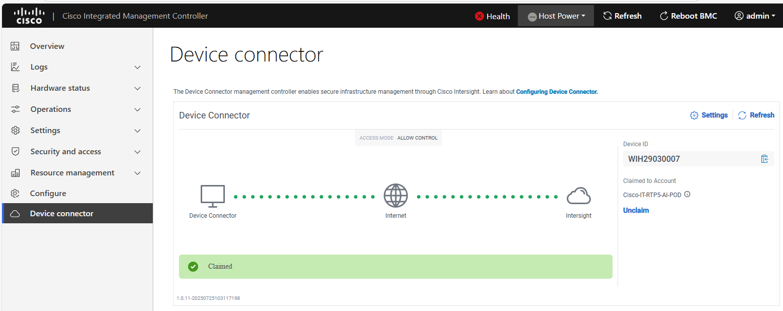
Step 2. Once the server is claimed into Intersight, it will appear under Operate > Servers. Server Inventory and Metrics can be viewed and the server’s BMC and KVM interfaces can be brought up from Intersight. In order for either of these interfaces to be reached, the machine that is logged into Intersight must have routable access to the C885As’ BMC IP addresses.
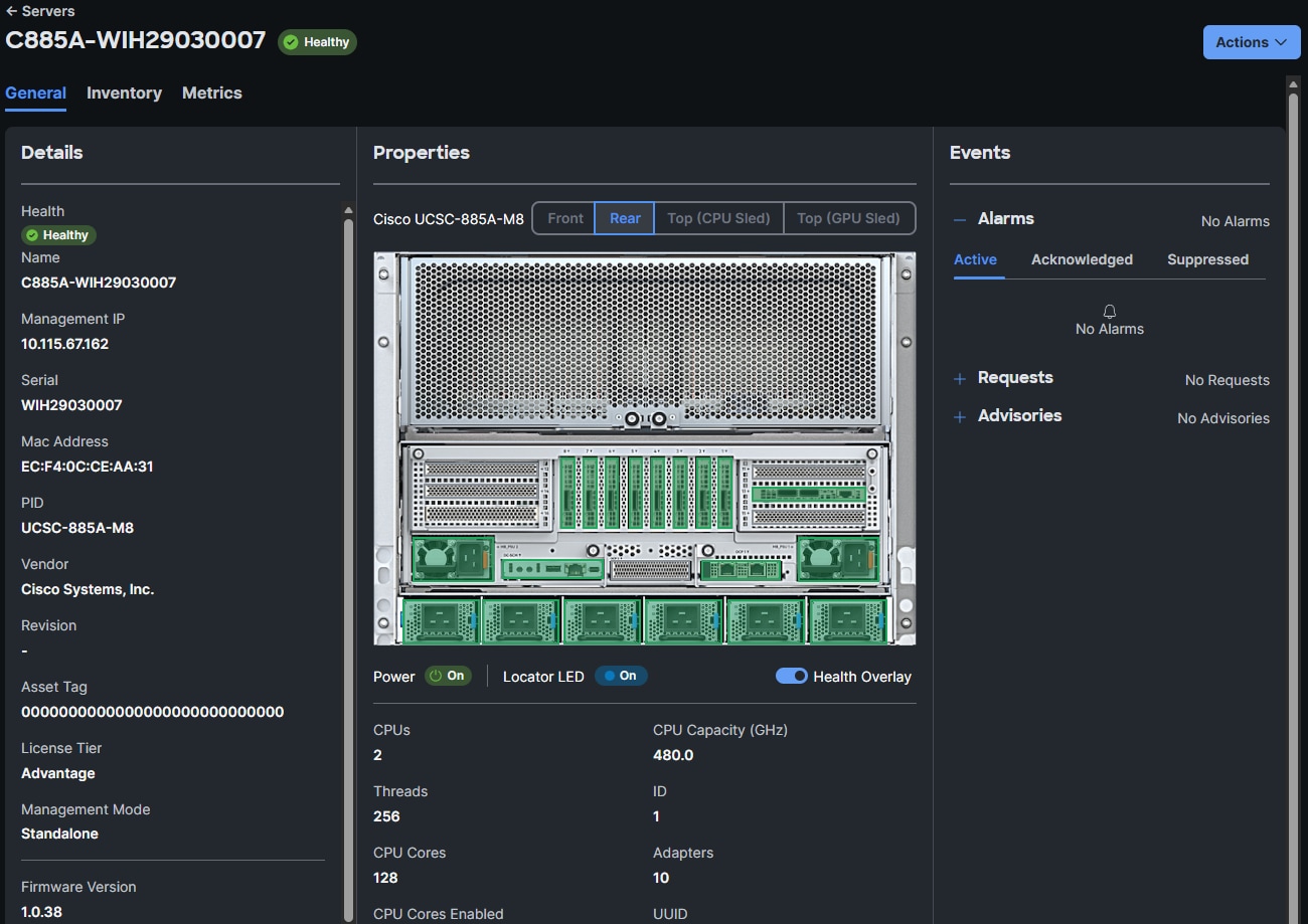
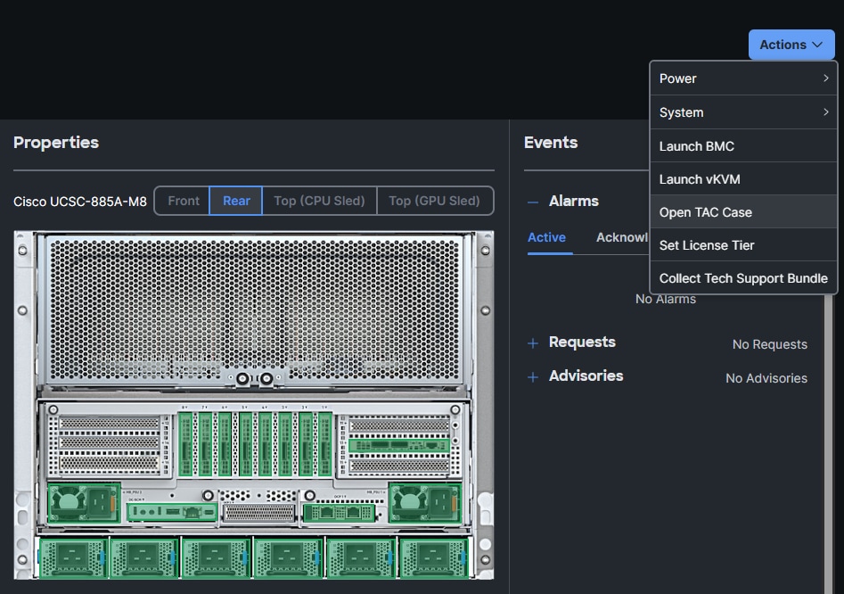
Procedure 5. Update Cisco UCS C885A Firmware
Note: It is important to update Cisco UCS C885A firmware to at least the Suggested Release from https://software.cisco.com/download/home/286337202/type/283850974/release/1.1(0.250025). This procedure will show an update to what is currently the latest release – version 1.2(0.250011). The firmware will need to be updated individually on each server. The firmware downloads include a PCIe Switch Update Tool to update the PCIe switches between the GPUs and backend NIC cards, a server firmware upgrade script to update mainly BIOS and BMC firmware, a firmware tar.gz file containing the updated firmware, and a firmware hardware update utility ISO to update firmware in all hardware NICs in the server. Note that at the time of publication, only the version 1.2 firmware includes the PCIE Switch Update Tool.
Step 1. Download all the desired UCS C885A M8 firmware release files from https://software.cisco.com.
Step 2. If your download included The PCIE Switch Update Tool, it can be run on Ubuntu 22.04.5 LTS or on RHEL 9.4, since Red Hat CoreOS 4.16-4.18 is based off RHEL 9.4, the PCIe switch update can be done from CoreOS. To upgrade the PCIe switch software with Red Hat CoreOS 4.18, from the OpenShift Installer VM where the pcie-switch-update-tool-04.18.00.00.zip file was downloaded to, run the following:
unzip pcie-switch-update-tool-04.18.00.00.zip
chmod +x pcie-switch-update-tool-04.18.00.00.run
scp pcie-switch-update-tool-04.18.00.00.run core@<c885a-hostname-or-IP>:/var/home/core/
ssh core@<c885a-hostname-or-IP>
sudo ./pcie-switch-update-tool-04.18.00.00.run
Enter option 1. If the Firmware Version is less than 04.18.00.00, then rerun the tool and select option 2.
If option 2, was entered, answer yes to the question.
When the update is completed, drain the node and reboot the node. Ssh back into the node and rerun the tool to verify the firmware update.
Step 3. The C885A BIOS and BMC update can be done from a Linux machine. In this example, it was done from the OpenShift Installer VM running RHEL 9.6. For this update, power off the C885A.
sudo dnf install python3.11
pip3.11 install prettytable
tar -xzvf ucs-c885a-m8-upgrade-script-v1.5.tar.gz
python3.11 ucs-c885a-m8-upgrade-v1.5.py -B ucs-c885a-m8-1.2.0.250011.tar.gz -U <user> -P <password> -I <BMC-IP> -D
Step 4. If any of the firmware components require update:
python3.11 ucs-c885a-m8-upgrade-v1.5.py -B ucs-c885a-m8-1.2.0.250011.tar.gz -U <user> -P <password> -I <BMC-IP> -F
The update will take at least 15 minutes to complete.
Step 5. To upgrade the remaining firmware on the server, launch the server’s KVM interface. To launch the KVM from Intersight, select Operate > Servers. Click the three dots to the right of the UCSC-885A-M8 server and select Launch vKVM. To launch the KVM from the BMC interface, select Operations > KVM and click Launch KVM. Once in the KVM window, from the Virtual Media drop-down list and Map image to map the HUU ISO file to the KVM. From the Boot Device drop-down list to select a one-time boot from CD. From the Host Power drop-down list to power cycle the C885A and reboot from the HUU ISO CD. Follow the prompts to update the remaining firmware.
Procedure 6. Set Boot Order if Using NVIDIA Base Command Manager (BCM)
If you use NVIDIA BCM to run training and fine-tuning jobs on the C885A servers, the server boot order needs to be set to PXE boot from the first front-end or N-S NIC. Complete the following steps to set this boot order on all Cisco UCS C885A servers.
Note: Since the front-end NICs are mainly used in a bond, the “no lacp suspend individual command” should be present on all switch ports connected to the C885A front-end NICs.
Step 1. In the Cisco UCS C885A BMC interface, select Hardware status > Inventory and LEDs > Network adapters. Identify the adapter(s) being used for the frontend network, expand them, and note the MAC addresses.
Step 2. From the server’s BMC interface, select Configure > Configure Boot Order. Scroll down to find the first N-S NIC by MAC address with PXE. Use the up arrow on the right to move this NIC to the top of the list. Select Reboot Host Immediately and click Save.
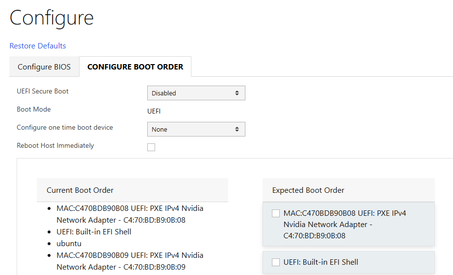
NVIDIA Base Command Manager (BCM)
This chapter contains the following:
● NVIDIA BCM InstallationNVIDIA BCM Installation
● MLPerf TrainingMLPerf Training
● Deploy GPUDirect RDMA on Backend FabricDeploy GPUDirect RDMA on Backend Fabric
NVIDIA BCM 10 was used in this lab validation to run ML Commons and other tests under the Simple Linux Utility for Resource Management (SLURM). BCM was used as a PXE boot target for the Cisco UCS C885A HGX Worker nodes to load an Ubuntu 22.04.4 LTS-based image with NVIDIA GPU utilities and software. NVIDIA BCM was installed on Ubuntu22.04.4 LTS in this validation on a single Cisco UCS C220 head node. BCM can also be installed on a pair of head nodes in an HA configuration. The BCM head node was connected to the front-end fabric compute leafs (where the C885As were also connected) with an LACP bonded connection that consisted of 2-100G connections from the Cisco VIC. On the bond, an IP in the management subnet was assigned and connected to a vPC in the fabric where the native VLAN for the vPC corresponded to the VLAN for the management subnet. Tagged VLAN interfaces on the bond allowed NFS and NFS over RDMA connections to storage. The NVIDIA BCM nodes were cabled according to Table 5 and mounted NFS storage from the NetApp Storage controllers.
Table 22. NVIDIA BCM Node Assignment
| Node Type |
Server Type |
Hostname |
IP |
CIMC IP |
| Head Node |
Cisco UCS C220 |
rtp5-hgx-mgt-06 |
10.115.90.115/26 |
10.115.90.7/26 |
| Worker |
Cisco UCS C885A M8 |
rtp5-hgx-hgpu-009 |
10.115.90.105 |
10.115.67.161 |
| Worker |
Cisco UCS C885A M8 |
rtp5-hgx-hgpu-010 |
10.115.90.106 |
10.115.67.162 |
| Worker |
Cisco UCS C885A M8 |
rtp5-hgx-hgpu-011 |
10.115.90.107 |
10.115.67.163 |
| Worker |
Cisco UCS C885A M8 |
rtp5-hgx-hgpu-012 |
10.115.90.108 |
10.115.67.164 |
Table 23. NVIDIA BCM Network Info
| Name |
Netmask Bits |
Base Address |
Domain Name |
| internalnet |
26 |
10.115.90.64 |
eth.cluster |
| ipminet |
26 |
10.115.67.128 |
ipmi.cluster |
| storagenet |
24 |
192.168.51.0 |
storage.cluster |
Procedure 1. Install NVIDIA BCM
NVIDIA BCM was installed on a Cisco UCS C-Series server using the NVIDIA Base Command Manager 10 Installation Manual. In the installation, Ubuntu 22.04.4 LTS was used as the underlying OS, and the SLURM Workload Manager and a type 2 network was installed.
Procedure 2. Configure BCM and Worker Nodes
Step 1. Using NVIDIA Base Command Manager 10 Administrator Manual, section 2, bring up the BCM View GUI.
Step 2. Using NVIDIA Base Command Manager 10 Administrator Manual, section 3, configure BCM.
Step 3. Using NVIDIA Base Command Manager 10 Administrator Manual, section 5, set up PXE boot and provision nodes with the base Ubuntu image.
Step 4. On one node, install all necessary drivers and tools, grab this image, and apply it to the other nodes.
Step 5. You can now run workloads such as SLURM on the nodes. For more information, see NVIDIA Base Command Manager 10 Administrator Manual, section 7.
Training Applications Run under NVIDIA BCM
Setup
The MLPerf Training benchmark suite comprises full system tests that stress models, software, and hardware for a range of machine learning (ML) applications. The open-source and peer-reviewed benchmark suite provides a level playing field for competition that drives innovation, performance, and energy efficiency for the entire industry.
The MLPerf Training v5.1 benchmark suite highlighting the rapid evolution and increasing richness of the AI ecosystem as well as significant performance improvements from new generations of systems.
Llama 2 70B-LoRA: Efficient LLM Fine-Tuning
The Llama 2 70B-LoRA utilizes the massive Llama 2 70B general LLM, fine-tuning it with Parameter-Efficient Fine-Tuning (PEFT) on the SCROLLS GovReport dataset. The primary task is high-quality document summarization, with results measured against the industry-standard ROUGE algorithm. Reflecting the trend toward complex, detailed analysis, the model is configured with a long context window of 8,192 tokens.
| Feature |
Detail |
| Model |
Llama 2 70B (70 billion parameters) |
| Method |
LoRA (Low-Rank Adaptation): This Parameter-Efficient Fine-Tuning (PEFT) technique drastically reduces training time and cost by only updating a small subset of the total parameters. |
| Task |
Document Summarization on the SCROLLS GovReport dataset, designed for instruction following and general productivity tasks. |
| Accuracy |
Performance is measured until the model reaches a target quality, evaluated using the ROUGE algorithm for summary accuracy. |
| Context |
The model utilizes a long context length of 8,192 tokens, reflecting the growing need for LLMs to process and understand lengthy documents. |
Setup instructions: https://github.com/mlcommons/training_results_v5.1/tree/main/Cisco/benchmarks/llama2_70b_lora/implementations/nemo
Results
For published MLPerf Results, please refer to MLCommons MLPerf Training Benchmark. Results for the Cisco UCS C885A with NVIDIA H200-SXM GPUs are shown.
OpenShift Installation and Configuration
This chapter contains the following:
● OpenShift InstallationOpenShift Installation
● Deploy GPUDirect RDMA on Backend FabricDeploy GPUDirect RDMA on Backend Fabric
For running OpenShift and OpenShift AI applications in this validation, a three-node OpenShift combo cluster (combined control plane and worker nodes) was built in the Cisco UCS X-Series chassis with Cisco UCS 9108 X-Series Direct Fabric Interconnects installed directly in the chassis. Supporting systems such as the OpenShift Installer Machine and DNS/DHCP servers should be run in another virtualization cluster (hypervisor of choice) or on bare metal servers. The Cisco UCS C885A servers were then added to the cluster as worker nodes. At the time of publication, virtual machines (VMs) could only be run on the combo nodes. Only containerized applications were run on the Cisco UCS C885As.
OpenShift 4.18 was installed using two of the four following two documents, depending on if you use Ansible:
In using both of these documents, you will not be setting up Cisco Nexus NXOS networking but instead will be setting up VXLAN EVPN networks using Nexus Dashboard. Also, it is only necessary to setup the NFS storage protocol. Setting up iSCSI and NVMe-TCP is not necessary in this environment.
For the AI portion of the OpenShift configuration, it is only necessary to install the NFS storage protocol and NFS and NFS FlexGroup Storage Classes. It is not necessary to install iSCSI or NVMe-TCP, but these can be installed if desired.
If you want to run OpenShift VMs, add OpenShift Virtualization with FlexPod Datacenter with Red Hat OpenShift Virtualization.
Add a Cisco UCS C885A M8 Worker Node to an OpenShift Cluster
To add one or more Cisco UCS C885A M8 servers to an existing OpenShift Cluster, complete the following.
Procedure 1. Setup the Cisco UCS C885A Server and CIMC
Deploy a Cisco UCS Server Profile in Cisco Intersight.
Step 1. Depending on the type of server added (Cisco UCS X-Series or Cisco UCS C-Series), clone the existing OCP-Worker template and create and adjust the template according to the server type.
Step 2. From the Configure > Templates page, to the right of the OCP-Worker template setup above, click the … and select Derive Profiles.
Step 3. Under the Server Assignment, select Assign Now and select the Cisco UCS server that will be added to the cluster as a Worker Node. Click Next.
Step 4. Assign the Server Profile an appropriate Name (for example, ocp-worker3) and select the appropriate Organization. Click Next.
Step 5. Click Derive.
Step 6. From the Infrastructure Service > Profiles page, to the right of the just-created profile, click the … and select Deploy. Select Reboot Immediately to Activate and click Deploy.
Step 7. Wait until the profile deploys and activates.
Step 8. Click the server profile and go to Configuration > Identifiers and Inventory tabs note the server’s management IP, serial number, and the MAC of address of network interface eno5.
Procedure 2. Create the Bare Metal Host (BMH)
Step 1. On the OCP-Installer VM, create the following yaml file (the example shown is for worker node worker4:
cat bmh.yaml
apiVersion: metal3.io/v1alpha1
kind: BareMetalHost
metadata:
name: worker-4
namespace: openshift-machine-api
spec:
online: True
bootMACAddress: C4:70:BD:B8:7C:EC
customDeploy:
method: install_coreos
externallyProvisioned: true
Note: The bootMACAddress can be obtained from the Cisco UCS C885A M8 CIMC interface under Inventory and LEDs > NETWORK ADAPTERS. It is the MAC Address of the first port for the adapter used for the N-S Network.
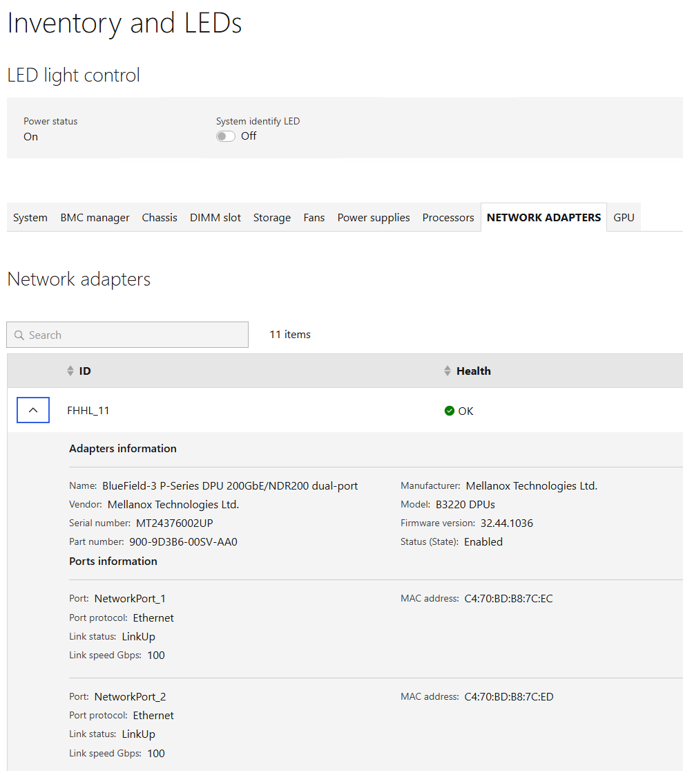
Step 2. Create the Bare Metal Host by typing the following:
oc project openshift-machine-api
oc create -f bmh.yaml
Step 3. Verify that the BMH is created by selecting Compute > Bare Metal Hosts in the OpenShift Console.
![]()
Note: With this method of creating the BMH, the server is not inspected, and some details such as Serial Number, Network Interfaces, and Disks are not retrieved from the server0.
Step 4. Click the three dots to the right of the newly added BMH and select Edit Bare Metal Host.
Step 5. Select Enable power management. Using the screenshot below, fill in the remaining parameters and click Save. Upon successful registration, the BMH should show Externally provisioned.
![]()
Note: It is critical to select Disable Certificate Verification.
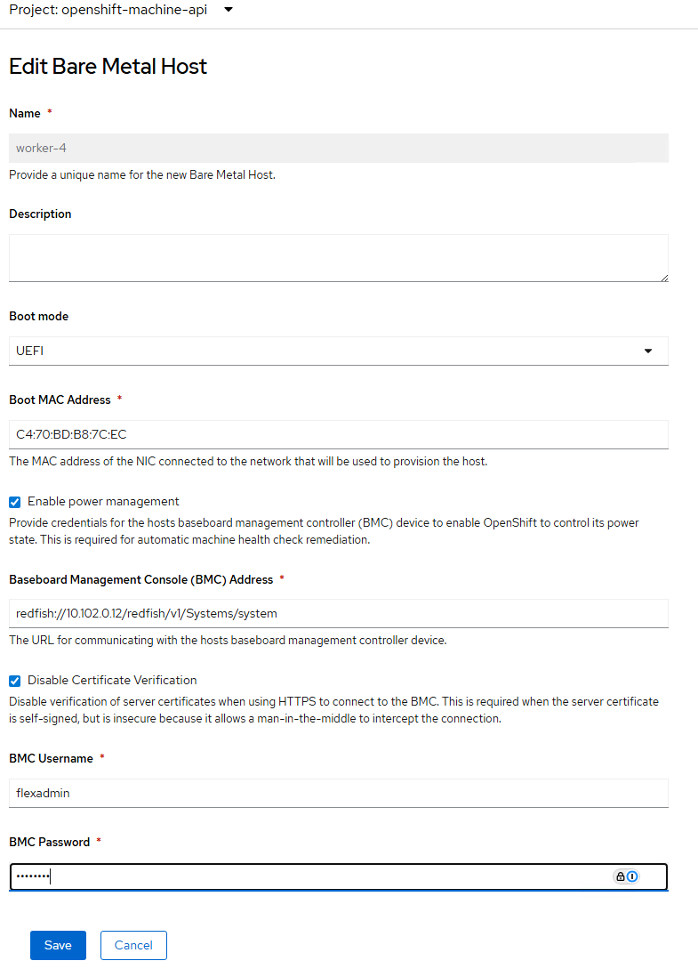
Step 6. In the OpenShift Console, select Compute > MachineSets. Click the … to the right of the worker MachineSet and choose Edit Machine count. Use the plus sign to increase the count by one. Click Save.
Step 7. Click Compute > Machines. A new machine in the Provisioning phase should now appear in the list.
![]()
Procedure 3. Adjust Networking for the Existing Workers
If adding a Cisco UCS C885A M8 Worker to an existing OpenShift cluster with servers attached behind fabric interconnects, the C885A M8 will use different networking than the FI-attached servers. We will add some node labels indicating how the server is attached and apply these labels to the existing NMState policies.
Step 1. For each existing Worker node that is FI-attached, apply a node label.
oc label node <node-name> net-type=fi-attached
Step 2. In the OpenShift console, select Networking > NodeNetworkConfigurationPolicy. For each policy being used with fabric interconnect attached worker nodes, starting with the interface policies then progressing to the bridge policies, select the policy, then select the YAML tab. Under nodeSelector:, replace “node-role.kubernetes.io/worker: ''” with “net-type: fi-attached.”
![]()
Step 3. Repeat this for all FI-attached worker policies.
Procedure 4. Install Red Hat CoreOS on the New Cisco UCS C885A M8 Worker(s)
Step 1. For each of the Cisco UCS C885A M8 server(s), in Cisco Intersight, select the server. Then select Inventory > Network Adapters. In the list of Network Adapters, select the adapter being used for the N-S or front end network (normally the first adapter in the list). Select Interfaces. The LACP bond interface will use the MAC Address for DCE Interface 1 for its MAC address. Use this MAC to build a DHCP reservation in your DHCP server. If the network card being used for the front end network is a Bluefield adapter, the network interface names for the two NICs will be ens2<slot-number>f0np0 and ens2<slot-number>f1np1. In this example, the two NICs are ens211f0np0 and ens211f1np1.
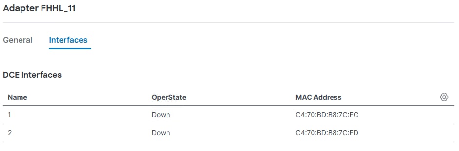
Step 2. Connect to the Red Hat Hybrid Cloud Console here: https://console.redhat.com/openshift/overview and log in with your Red Hat credentials. On the left, select Cluster List. Under Cluster List, click your cluster to open it.
Step 3. Select the Add Hosts tab. Click Add hosts.
Step 4. The Cisco UCS C885A M8 will use a VLAN tagged interface on top of an LACP bond interface to connect to the front end network fabric. Select Static IP, bridges, and bonds and click Next.
Step 5. Next to Configure via: select YAML view. In the YAML text box, click Start from scratch. Build and copy a YAML file specifying the LACP bond interface and then the VLAN-tagged interface on top of the bond into the text box. For this example, the following NMState YAML file was used:
interfaces:
- name: bond0
description: C885A LACP Bond with ports ens211f0np0 and ens211f1np1
type: bond
state: up
ipv4:
dhcp: false
enabled: false
ipv6:
enabled: false
link-aggregation:
mode: 802.3ad
options:
miimon: '100'
xmit_hash_policy: layer3+4
port:
- ens211f0np0
- ens211f1np1
mtu: 9000
- name: bond0.1022
description: vlan using bond0
type: vlan
state: up
vlan:
base-iface: bond0
id: 1022
ipv4:
dhcp: true
enabled: true
mtu: 1500
Step 6. Scroll down below the YAML box and enter the MAC address and Interface name of the two NICs specified in the YAML file, using Add another MAC to interface name mapping to add the second MAC and Interface name. If additional Cisco UCS C885A M8 hosts need to be added, select Add another host configuration and add them one at a time. Once all hosts are added, click Next.
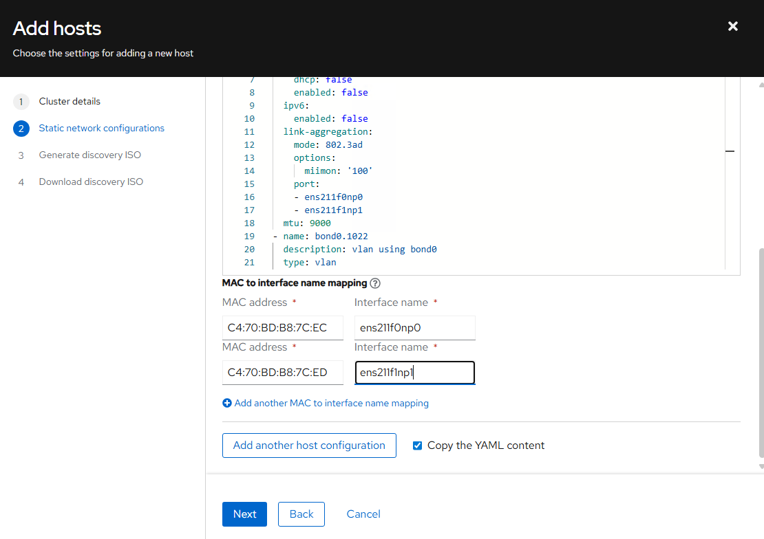
Step 7. For Provisioning type, select Minimal image file. Browse to and select the SSH public key file used in the original cluster installation. Click Generate Discovery ISO.
Step 8. Click Download Discovery ISO. The file will download to your machine. Click Close.
Step 9. For each Cisco UCS C885A M8, in Cisco Intersight, launch the server’s vKVM. In the vKVM, from the Virtual Media drop-down list to select Map image. Click Drop file here or click to upload. Navigate to and select the Discovery ISO in your Downloads folder and click Open. Click Upload.
Step 10. From the Boot Device drop-down list to select CD. From the Host Power drop-down list to select Power cycle. Click Confirm. The server will reboot and boot from the Discovery ISO.
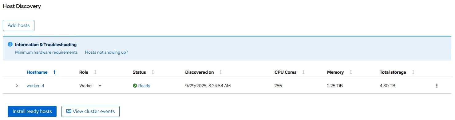
Step 12. Click the arrow to the left of the server(s) Hostname. Make sure the correct M.2 boot disk is selected.
Step 13. Click Install ready hosts. The installation of CoreOS will take several minutes.
Note: Once the CoreOS installation completes (Status of Installed), the server will reboot, boot CoreOS, and reboot a second time.
Step 14. Once the server has booted into CoreOS, in the vKVM from the Virtual Media drop-down list to select Eject image.
Step 15. In the OpenShift Console, select Compute > Nodes. Once the server reboots have completed, the newly added worker(s) will appear in the list as Discovered. Click Discovered and then select Approve. Click Not Ready and select Approve.
Step 16. To link the Bare Metal Host to the Machine, select Compute > Machines. For the newly-added machine in the Provisioning Phase, note the last five characters in the machine name (for example, bqz2k).

Step 17. Select Compute > Bare Metal Hosts. Select the BMH above the newly added BMH (for example, worker2). Select the YAML tab. Select and copy the entire consumerRef field right underneath the externallyProvisioned field.
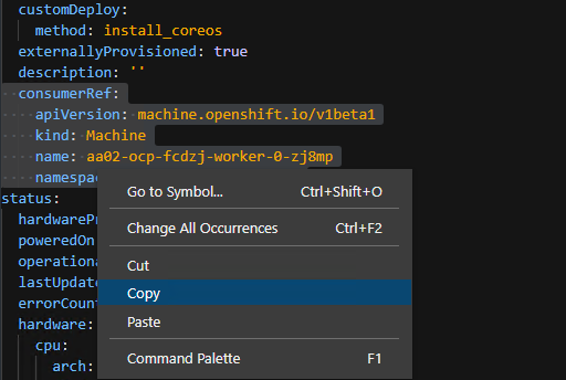
Step 18. Select Compute > Bare Metal Hosts. Select the BMH for the newly added BMH (for example, worker3). Select the YAML tab. Place the cursor at the end of the externallyProvisioned: true line and press Enter to insert a new line. Backspace to the beginning of the line and then paste in the consumerRef field from the previous step. Replace the last five characters in the name field with the five characters noted above (for example, bqz2k).
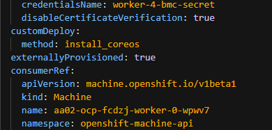
Step 19. Click Save. Click Compute > Machines. The newly added machine should now be in the Provisioned Phase.
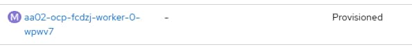
Step 20. To link this machine to the node, click this newly added machine and select the YAML tab. Under spec, select and copy the entire providerID line.
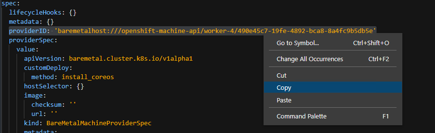
Step 21. Select Compute > Nodes. Select the newly-added node and select the YAML tab. Scroll down to find the spec field. Select and delete the {} to the right of spec: and press Enter to add a line. Paste in the providerID field with a two space indention and click Save.
Note: The OpenShift nodes update frequently, and it will be necessary if an update has occurred to reload the YAML tab. After reloading, you may need to make the changes again.
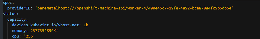
Step 22. Select Compute > Bare Metal Hosts. The newly-added BMH should now be linked to a node.
![]()
Step 23. Select Compute > Machines. The newly-added machine should now be in the Provisioned as node Phase and should be linked to the node.

Procedure 5. Setup NFS Networking for the Newly Added Host(s)
Step 1. Label each newly added node(s) with net-type=switch-attached
oc label node worker-4 net-type=c885a
Step 2. Add the NFS VLAN to the bond with a Node Network Configuration Policy (NNCP) file.
cat c885-bond0.3051.yaml
apiVersion: nmstate.io/v1
kind: NodeNetworkConfigurationPolicy
metadata:
name: c885-ocp-nfs-policy
spec:
nodeSelector:
net-type: c885a
desiredState:
interfaces:
- name: bond0.3051
description: VLAN 3051 using bond0
type: vlan
state: up
ipv4:
dhcp: true
enabled: true
ipv6:
enabled: false
vlan:
base-iface: bond0
id: 3051
Step 3. Add the NNCP to OpenShift.
oc create -f c885-bond0.3051.yaml
Step 4. Verify the addition in the OpenShift web console by checking Networking > NodeNetworkConfigurationPolicy.
Step 5. SSH to the C885A(s) and using the “ifconfig -a” command to verify the addition.
Procedure 6. Create a new node label for Cisco UCS C885A M8 GPU worker nodes
This is done so that machine configs (requires reboot) and other policies can be applied without impacting all nodes in the cluster. GPU-dense nodes may require different policies so creating roles allow you to apply, especially machine configurations that require a reboot.
Step 1. Log into the OpenShift Installer machine and label the UCS C885A nodes.
oc get nodes
oc label node <node_name> node-role.kubernetes.io/worker-ucs-c885a=
oc get nodes
Step 2. Repeat for all UCS C885A nodes in the cluster.
Procedure 7. Create a UCS C885A Machine Config Pool
Step 1. Create the following YAML file on the OpenShift Installer VM:
cat worker-ucs-c885a-mcp.yaml
apiVersion: machineconfiguration.openshift.io/v1
kind: MachineConfigPool
metadata:
name: worker-ucs-c885a
spec:
machineConfigSelector:
matchExpressions:
- {key: machineconfiguration.openshift.io/role, operator: In, values: [worker,worker-ucs-c885a]}
nodeSelector:
matchLabels:
node-role.kubernetes.io/worker-ucs-c885a: ""
Step 2. Add this Machine Config Pool to the OpenShift cluster.
oc create -f worker-ucs-c885a-mcp.yaml
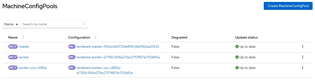
Step 3. Click the worker-ucs-c885a Machine Config Pool and verify the correct number of machines in the pool.
Procedure 8. Set UCS C885A Kernel Arguments
Step 1. Create the following YAML file on the OpenShift Installer VM:
cat 99-worker-ucs-c885a-kernel-args.yaml
apiVersion: machineconfiguration.openshift.io/v1
kind: MachineConfig
metadata:
labels:
machineconfiguration.openshift.io/role: worker-ucs-c885a
name: 99-worker-ucs-c885a-kernel-args
spec:
kernelArguments:
- "module_blacklist=irdma"
- intel_iommu=off
- amd_iommu=off
- iommu=pt
Step 2. Add this Machine Config to the Openshift cluster.
oc create -f 99-worker-ucs-c885a-kernel-args.yaml
Step 3. Wait until the worker-ucs-c885a Machine Config Pool has moved from “Updating” to “Up to date”.
Step 4. Log into each UCS C885A node and check kernel parameters.
ssh core@<node_name>
cat /proc/cmdline
BOOT_IMAGE=(hd0,gpt3)/boot/ostree/rhcos-f9a3486fdae1cf8a2d934693030c00eb1a10f0ae8b16605640186dbb75fc9e0f/vmlinuz-5.14.0-427.107.1.el9_4.x86_64 ignition.platform.id=metal systemd.unified_cgroup_hierarchy=1 cgroup_no_v1=all psi=0 module_blacklist=irdma intel_iommu=off amd_iommu=off iommu=pt ostree=/ostree/boot.1/rhcos/f9a3486fdae1cf8a2d934693030c00eb1a10f0ae8b16605640186dbb75fc9e0f/0 root=UUID=e3b53ab5-a973-402c-a25a-2facc91c9e9a rw rootflags=prjquota boot=UUID=11182f97-0a8c-4d85-9751-92f549f49d03
lsmod | grep irdma
<no output expected>
Procedure 9. Remove the NVIDIA GPU Operator
If the NVIDIA GPU Operator has already been installed it should be removed at this point.
Step 1. In the OpenShift cluster web interface, select Operators > Installed Operators. At the top, select the nvidia-gpu-operator project. Select NVIDIA GPU Operator. Select the ClusterPolicy tab. To the right of the gpu-cluster-policy, click the three dots and select Delete Cluster Policy followed by Delete.
Step 2. From the Actions drop-down list, select Uninstall Operator followed by Uninstall.
Step 3. Select Home > Projects. To the right of the nvidia-gpu-operator project, click the three dots and select Delete Project. In the popup, enter nvidia-gpu-operator and select Delete.
Procedure 10. Modify the Node Feature Discovery Operator
Step 1. If the Node Feature Discovery Operator has not been installed, in the OpenShift console, select Operators > OperatorHub. In the search box, type Node Feature. Select Node Feature Discovery Operator. Click Install. Click Install again to deploy the operator. When the operator is installed, click View Operator.
Step 2. If the Node Feature Discovery Operator was not installed in the previous step, in the OpenShift console, select Operators > Installed Operators. At the top, select All Projects then select Node Feature Discovery Operator.
Step 3. Select the NodeFeatureDiscovery tab. If a nfd-instance is present, click the ellipses to the right and select Delete NodeFeatureDiscovery followed then click Delete to delete the policy.
Step 4. On the installer VM, create the following YAML file:
cat nodefeaturediscovery.yaml
apiVersion: nfd.openshift.io/v1
kind: NodeFeatureDiscovery
metadata:
name: nfd-instance
namespace: openshift-nfd
spec:
instance: ''
operand:
servicePort: 12000
prunerOnDelete: false
topologyUpdater: false
workerConfig:
configData: |
core:
sleepInterval: 60s
sources:
pci:
deviceClassWhitelist:
- "02"
- "03"
- "0200"
- "0207"
- "12"
deviceLabelFields:
- "vendor"
Step 5. Create the nfd-instance:
oc create -f nodefeaturediscovery.yaml
Step 6. Wait for the nfd-instance to reach a Status of Available, Upgradable.
Step 7. If after a few minutes the nfd-instance has not progressed from the Status of Condition: Degraded, select Workloads > Pods. If the nfd-gc pod has a Status of CreateContainerConfigError, select Workloads > Deployments. Click nfd-gc and select the YAML tab. Under spec:, change the runasNonRoot: property from true to false. Click Save. Acknowledge the warning and click Save again. Click Workloads > Pods. A new nfd-gc pod should now be Running. From Operators > Installed Operators and the NodeFeatureDiscovery tab, the nfd-instance should now have a Status of Available, Upgradeable.
Note: The old nfd-gc pod is also still present, but this is not an issue.
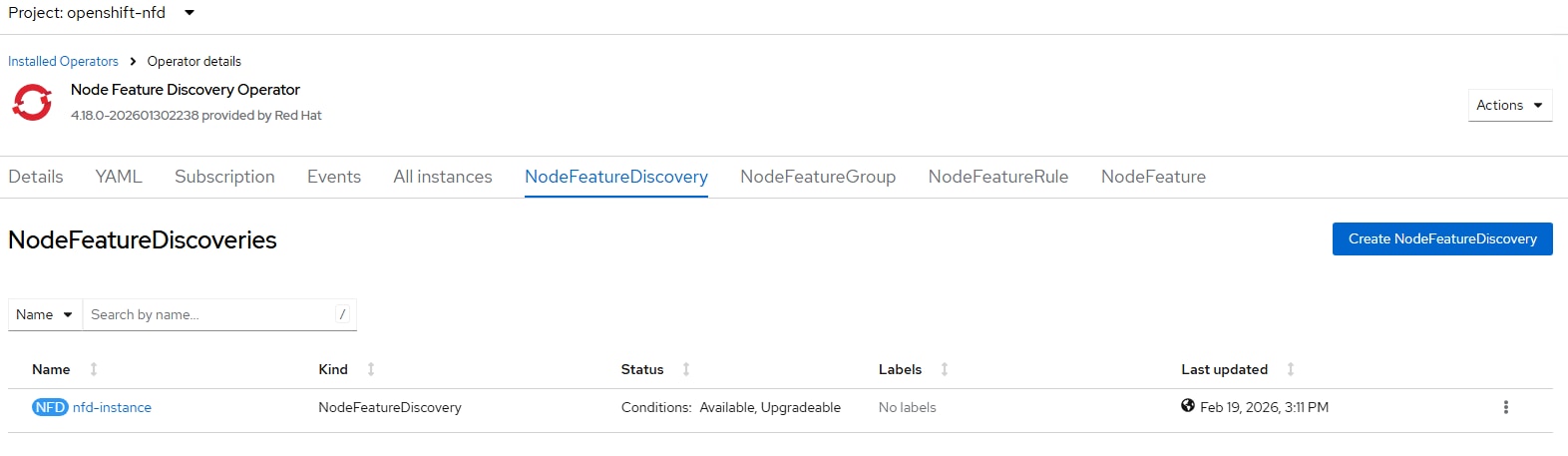
Procedure 11. Deploy the NVIDIA Network Operator
Step 1. In the OpenShift console, select Operators > OperatorHub. In the search box, type NVIDIA. Select NVIDIA Network Operator.
Step 2. Click Install. Click Install again to deploy the operator.
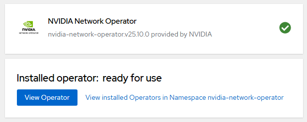
Step 3. When the operator is installed, click View Operator.
Procedure 12. Deploy the NVIDIA GPU Operator
Step 1. In the OpenShift console, select Operators > OperatorHub. In the search box, type NVIDIA. Select NVIDIA GPU Operator.
Step 2. Click Install. Click Install again to deploy the operator.
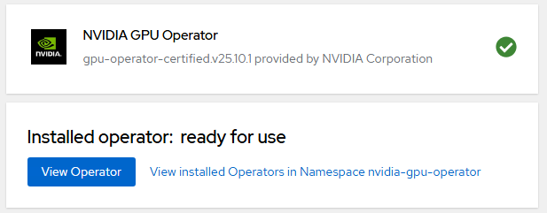
Step 3. When the operator is installed, click View Operator.
Deploy GPUDirect RDMA on Backend Fabric
The NVIDIA network Operator manages NVIDIA networking resources and networking related components such as drivers and device plugins to enable NVIDIA GPUDirect RDMA workloads. NVIDA Network Operator was deployed earlier. Verify that the previously deployed Network Operator is installed and running.
Procedure 1. Install NVIDIA Network Operator Nic Cluster Policy
Step 1. Verify that the previously deployed Network Operator is installed and running:
oc get pods -n nvidia-network-operator
NAME READY STATUS RESTARTS AGE
nvidia-network-operator-controller-manager-54fc877bf5-mm5sp 1/1 Running 0 19m
Step 2. Create the NicClusterPolicy custom resource file:
cat nic-cluster-policy.yaml
apiVersion: mellanox.com/v1alpha1
kind: NicClusterPolicy
metadata:
name: nic-cluster-policy
spec:
rdmaSharedDevicePlugin:
config: |
{
"configList": [
{
"resourceName": "rdma_shared_device_a",
"rdmaHcaMax": 63,
"selectors": {
"ifNames": [
"ens201np0",
"ens202np0",
"ens203np0",
"ens204np0",
"ens205np0",
"ens206np0",
"ens207np0",
"ens208np0"
]
}
},
{
"resourceName": "rdma_shared_device_b",
"rdmaHcaMax": 63,
"selectors": {
"ifNames": ["bond0"]
}
}
]
}
image: k8s-rdma-shared-dev-plugin
repository: nvcr.io/nvidia/mellanox
version: sha256:78f01edc4cc6f5f1282b5e4bf0a0d0291ee97c1bdb372616daa5367e1070269e
ofedDriver:
readinessProbe:
initialDelaySeconds: 10
periodSeconds: 30
forcePrecompiled: false
terminationGracePeriodSeconds: 300
livenessProbe:
initialDelaySeconds: 30
periodSeconds: 30
upgradePolicy:
autoUpgrade: true
drain:
deleteEmptyDir: true
enable: true
force: true
timeoutSeconds: 300
podSelector: ''
maxParallelUpgrades: 1
safeLoad: false
waitForCompletion:
timeoutSeconds: 0
startupProbe:
initialDelaySeconds: 10
periodSeconds: 20
image: doca-driver
repository: nvcr.io/nvidia/mellanox
version: doca3.2.0-25.10-1.2.8.0-2
env:
- name: ENABLE_NFSRDMA
value: "true"
- name: UNLOAD_STORAGE_MODULES
value: "true"
- name: RESTORE_DRIVER_ON_POD_TERMINATION
value: "true"
- name: CREATE_IFNAMES_UDEV
value: "true"
Step 3. Add the NicClusterPolicy to the OpenShift cluster:
oc create -f nic-cluster-policy.yaml
Step 4. Verify that all nvidia-network-operator pods are running:
oc get pods -n nvidia-network-operator
NAME READY STATUS RESTARTS AGE
mofed-rhcos4.18-6468b8fcdb-ds-vd5vf 2/2 Running 0 4h51m
nvidia-network-operator-controller-manager-7f7ff45c45-nltnx 1/1 Running 0 4d2h
rdma-shared-dp-ds-rb4nm 1/1 Running 0 4h47m
Note: One mofed- pod should be listed for each Cisco UCS C885A M8 server.
Step 5. To verify drivers loaded, execute the following commands using the mofed- pod on each UCS C885A:
oc project nvidia-network-operator
oc exec -it mofed-rhcos4.18-6468b8fcdb-ds-vd5vf -- bash
Defaulted container "mofed-container" out of: mofed-container, openshift-driver-toolkit-ctr, network-operator-init-container (init)
ofed_info -s
OFED-internal-25.10-1.2.8:
ibdev2netdev -v
0000:69:00.0 mlx5_0 (MT4129 - 30-100363-01) MCX715105AS-WEAT CX-7 1x400GbE QSFP112 PCIe Gen5 x16 VPI NIC fw 28.43.2026 port 1 (ACTIVE) ==> ens202np0 (Up)
0000:09:00.0 mlx5_1 (MT4129 - 30-100363-01) MCX715105AS-WEAT CX-7 1x400GbE QSFP112 PCIe Gen5 x16 VPI NIC fw 28.43.2026 port 1 (ACTIVE) ==> ens204np0 (Up)
0000:53:00.0 mlx5_2 (MT4129 - 30-100363-01) MCX715105AS-WEAT CX-7 1x400GbE QSFP112 PCIe Gen5 x16 VPI NIC fw 28.43.2026 port 1 (ACTIVE) ==> ens201np0 (Up)
0000:23:00.0 mlx5_3 (MT4129 - 30-100363-01) MCX715105AS-WEAT CX-7 1x400GbE QSFP112 PCIe Gen5 x16 VPI NIC fw 28.43.2026 port 1 (ACTIVE) ==> ens203np0 (Up)
0000:f1:00.0 mlx5_4 (MT4129 - 30-100363-01) MCX715105AS-WEAT CX-7 1x400GbE QSFP112 PCIe Gen5 x16 VPI NIC fw 28.43.2026 port 1 (ACTIVE) ==> ens205np0 (Up)
0000:89:00.0 mlx5_5 (MT41692 - 900-9D3B6-00SV-AA0) BlueField-3 P-Series DPU 200GbE/NDR200 dual-port QSFP-DD112, PCIe Gen5.0 x16 FHHL, Crypto Disabled, 32GB DDR5, BMC, Tall Bracket fw 32.45.1020 port 1 (ACTIVE) ==> ens214f0np0 (Up)
0000:89:00.1 mlx5_6 (MT41692 - 900-9D3B6-00SV-AA0) BlueField-3 P-Series DPU 200GbE/NDR200 dual-port QSFP-DD112, PCIe Gen5.0 x16 FHHL, Crypto Disabled, 32GB DDR5, BMC, Tall Bracket fw 32.45.1020 port 1 (ACTIVE) ==> ens214f1np1 (Up)
0000:8f:00.0 mlx5_7 (MT4129 - 30-100363-01) MCX715105AS-WEAT CX-7 1x400GbE QSFP112 PCIe Gen5 x16 VPI NIC fw 28.43.2026 port 1 (ACTIVE) ==> ens207np0 (Up)
0000:cd:00.0 mlx5_8 (MT4129 - 30-100363-01) MCX715105AS-WEAT CX-7 1x400GbE QSFP112 PCIe Gen5 x16 VPI NIC fw 28.43.2026 port 1 (ACTIVE) ==> ens206np0 (Up)
0000:9c:00.0 mlx5_9 (MT4129 - 30-100363-01) MCX715105AS-WEAT CX-7 1x400GbE QSFP112 PCIe Gen5 x16 VPI NIC fw 28.43.2026 port 1 (ACTIVE) ==> ens208np0 (Up)
0000:4d:00.0 mlx5_bond_0 (MT41692 - 900-9D3B6-00SV-AA0) BlueField-3 P-Series DPU 200GbE/NDR200 dual-port QSFP-DD112, PCIe Gen5.0 x16 FHHL, Crypto Disabled, 32GB DDR5, BMC, Tall Bracket fw 32.45.1020 port 1 (ACTIVE) ==> bond0 (Up)
Procedure 2. Install Virtual Machine (VM) Network Bridge on UCS C885A Node(s)
Now that updated mlx5 drivers are in place, if you have installed OpenShift Virtualization and would like to run VMs on the C885A node(s), install the VM network bridge on these node(s).
Step 1. Add the VM network bridge to the bond with a Node Network Configuration Policy (NNCP) file.
cat c885-vm-network-bridge.yaml
apiVersion: nmstate.io/v1
kind: NodeNetworkConfigurationPolicy
metadata:
name: c885-br-vm-network-policy
spec:
nodeSelector:
net-type: c885
desiredState:
interfaces:
- name: br-vm-network
description: Linux bridge with bond0 as a port
type: linux-bridge
state: up
ipv4:
dhcp: false
enabled: false
ipv6:
enabled: false
bridge:
options:
stp:
enabled: false
port:
- name: bond0
Step 2. Add the NNCP to OpenShift.
oc create -f c885-vm-network-bridge.yaml
Step 3. Verify the addition in the OpenShift web console by checking Networking > NodeNetworkConfigurationPolicy.
Step 4. SSH to the C885A(s) and use the ifconfig -a command to verify the addition.
Procedure 3. Install NVIDIA GPU Operator Cluster Policy
Step 1. In the OpenShift cluster web interface select Operators > Installed Operators. Select Project nvidia-gpu-operator, then select NVIDIA GPU Operator. Click the ClusterPolicy tab.
Step 2. On the installer VM, create the following YAML file:
cat clusterpolicy.yaml
apiVersion: nvidia.com/v1
kind: ClusterPolicy
metadata:
name: gpu-cluster-policy
spec:
vgpuDeviceManager:
config:
default: default
enabled: true
migManager:
config:
default: all-disabled
name: default-mig-parted-config
enabled: true
operator:
defaultRuntime: crio
initContainer: {}
runtimeClass: nvidia
use_ocp_driver_toolkit: true
dcgm:
enabled: true
gfd:
enabled: true
dcgmExporter:
config:
name: ''
serviceMonitor:
enabled: true
enabled: true
cdi:
default: false
enabled: true
driver:
licensingConfig:
nlsEnabled: true
secretName: ''
kernelModuleType: auto
certConfig:
name: ''
kernelModuleConfig:
name: ''
upgradePolicy:
autoUpgrade: true
drain:
deleteEmptyDir: false
enable: false
force: false
timeoutSeconds: 300
maxParallelUpgrades: 1
maxUnavailable: 25%
podDeletion:
deleteEmptyDir: false
force: false
timeoutSeconds: 300
waitForCompletion:
timeoutSeconds: 0
repoConfig:
configMapName: ''
virtualTopology:
config: ''
enabled: true
useNvidiaDriverCRD: false
devicePlugin:
config:
name: ''
default: ''
mps:
root: /run/nvidia/mps
enabled: true
gdrcopy:
enabled: false
kataManager:
config:
artifactsDir: /opt/nvidia-gpu-operator/artifacts/runtimeclasses
mig:
strategy: single
sandboxDevicePlugin:
enabled: true
validator:
plugin:
env: []
nodeStatusExporter:
enabled: true
daemonsets:
rollingUpdate:
maxUnavailable: '1'
updateStrategy: RollingUpdate
sandboxWorkloads:
defaultWorkload: container
enabled: false
gds:
enabled: true
image: nvidia-fs
repository: nvcr.io/nvidia/cloud-native
version: 2.26.6
vgpuManager:
enabled: false
vfioManager:
enabled: true
toolkit:
installDir: /usr/local/nvidia
enabled: true
Note: The ClusterPolicy shown above enables NVIDIA GPU Direct Storage (GDS) which works with NetApp NFS over RDMA on the FE fabric. If you do not want to enable this feature, change gds: enabled: to false. Changing this setting will not affect GPU Direct on the BE fabric.
Step 3. Create the ClusterPolicy:
oc create -f clusterpolicy.yaml
Step 4. From the OpenShift Installer VM, check the pod status waiting for all pods to get to the Running status.
oc project nvidia-gpu-operator
oc get pods
NAME READY STATUS RESTARTS AGE
gpu-feature-discovery-4bmwr 1/1 Running 0 2m14s
gpu-operator-7ccfc5879b-6k2m7 1/1 Running 0 23h
nvidia-container-toolkit-daemonset-qpl4p 1/1 Running 0 2m14s
nvidia-cuda-validator-2mfbz 0/1 Completed 0 17s
nvidia-dcgm-exporter-fvxvh 1/1 Running 0 2m14s
nvidia-dcgm-l6bjw 1/1 Running 0 2m14s
nvidia-device-plugin-daemonset-7kfxm 1/1 Running 0 2m14s
nvidia-driver-daemonset-418.94.202601202224-0-9mjjn 2/3 CrashLoopBackOff 3 (12s ago) 2m23s
nvidia-mig-manager-r4t25 1/1 Running 0 2m14s
nvidia-node-status-exporter-47zz7 1/1 Running 0 2m20s
nvidia-operator-validator-dfzwh 1/1 Running 0 2m14s
Note: What is shown here reflects a setup with one Cisco UCS C885A server. For multiple servers, corresponding multiple copies of each pod will be present.
Step 5. In your environment, if the nvidia-driver-daemonset pod(s) show the CrashLoopBackOff Status as shown above, repeat the following steps for each nvidia-driver-daemonset pod:
a. In the OpenShift console, select Workloads > Pods and select the nvidia-gpu-operator Project.
b. Click the first nvidia-driver-daemonset pod in the CrashLoopBackOff Status. Select the Terminal tab.
c. Verify that the nvidia_fs kernel module is loaded.
lsmod | grep nvidia
d. If nvidia_fs is present, remove it.
rmmod nvidia_fs
e. Repeat these steps for each nvidia-driver-daemonset pod in the CrashLoopBackOff Status.
Note: This is a temporary workaround until this issue is fixed by NVIDIA. This workaround will need to be repeated any time the nvidia-driver daemonset pod is restarted, including server reboots.
Step 6. From the OpenShift Installer VM, check the pod status waiting for all pods to get to the Running status.
oc get pods
NAME READY STATUS RESTARTS AGE
gpu-feature-discovery-4bmwr 1/1 Running 0 23m
gpu-operator-7ccfc5879b-6k2m7 1/1 Running 0 24h
nvidia-container-toolkit-daemonset-qpl4p 1/1 Running 0 23m
nvidia-cuda-validator-2mfbz 0/1 Completed 0 21m
nvidia-dcgm-exporter-fvxvh 1/1 Running 0 23m
nvidia-dcgm-l6bjw 1/1 Running 0 23m
nvidia-device-plugin-daemonset-7kfxm 1/1 Running 0 23m
nvidia-driver-daemonset-418.94.202601202224-0-9mjjn 3/3 Running 11 (5m36s ago) 23m
nvidia-mig-manager-r4t25 1/1 Running 0 23m
nvidia-node-status-exporter-47zz7 1/1 Running 0 23m
nvidia-operator-validator-dfzwh 1/1 Running 0 23m
Step 7. In the OpenShift cluster web interface, the gpu-cluster-policy will also show a Status of “State: ready.”
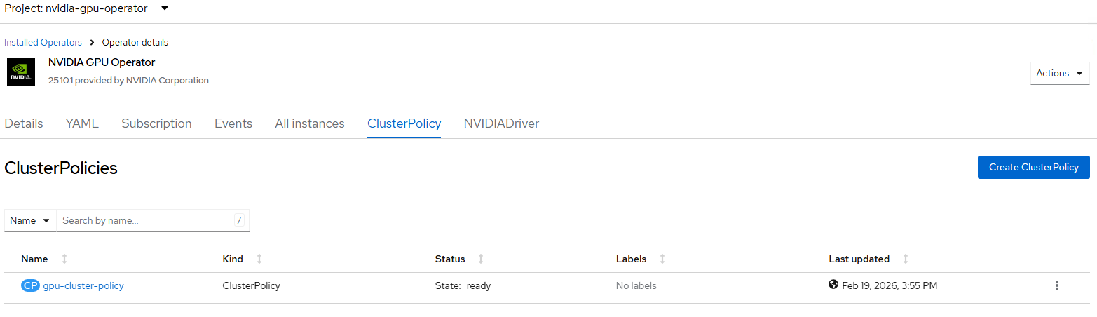
Procedure 4. Set the MTU of BE Interfaces to 9000 and Assigning IPs
The BE network interfaces by default have MTU 1500 and no IP address assigned.
Step 1. To set MTU 9000 and assign an access port style IP address to each BE interface of a Cisco UCS C885A server, create a YAML file as follows:
cat c885-be-jumbo-w4.yaml
apiVersion: nmstate.io/v1
kind: NodeNetworkConfigurationPolicy
metadata:
name: c885-be-jumbo-policy-worker-4
spec:
nodeSelector:
kubernetes.io/hostname: worker-4
desiredState:
interfaces:
- name: ens201np0
type: ethernet
state: up
mtu: 9000
ipv4:
enabled: true
address:
- ip: 192.168.100.1
prefix-length: 24
ipv6:
enabled: false
- name: ens202np0
type: ethernet
state: up
mtu: 9000
ipv4:
enabled: true
address:
- ip: 192.168.100.2
prefix-length: 24
ipv6:
enabled: false
- name: ens203np0
type: ethernet
state: up
mtu: 9000
ipv4:
enabled: true
address:
- ip: 192.168.100.3
prefix-length: 24
ipv6:
enabled: false
- name: ens204np0
type: ethernet
state: up
mtu: 9000
ipv4:
enabled: true
address:
- ip: 192.168.100.4
prefix-length: 24
ipv6:
enabled: false
- name: ens205np0
type: ethernet
state: up
mtu: 9000
ipv4:
enabled: true
address:
- ip: 192.168.100.5
prefix-length: 24
ipv6:
enabled: false
- name: ens206np0
type: ethernet
state: up
mtu: 9000
ipv4:
enabled: true
address:
- ip: 192.168.100.6
prefix-length: 24
ipv6:
enabled: false
- name: ens207np0
type: ethernet
state: up
mtu: 9000
ipv4:
enabled: true
address:
- ip: 192.168.100.7
prefix-length: 24
ipv6:
enabled: false
- name: ens208np0
type: ethernet
state: up
mtu: 9000
ipv4:
enabled: true
address:
- ip: 192.168.100.8
prefix-length: 24
ipv6:
enabled: false
Step 2. Add the NodeNetworkConfigurationPolicy to OpenShift:
oc create -f c885-be-jumbo-w4.yaml
Step 3. Verify the NodeNetworkConfigurationPolicy has been applied; go to Networking > NodeNetworkConfigurationPolicy in the OpenShift console.
![]()
Step 4. Repeat this process using different IPs in the same subnet for all Cisco UCS C885A nodes.
Procedure 5. Testing the BE Fabric and GPU Direct RDMA
Both the BE Network and the GPU Direct RDMA functionality can be tested with a NCCL test on two or more Cisco UCS C885A servers connected to a BE Fabric. For examples of running these tests, check https://github.com/schmaustech/nvidia-tools-image.
Deploy NetApp NFS over RDMA with NVIDIA GPU Direct Storage (GDS)
For the NetApp NFS over RDMA with NVIDIA GPU Direct Storage setup, a different validation lab was used. In this lab, the main NetApp controller interfaces were setup as port channels connected to vPCs on the Nexus switches. NFS over RDMA was setup on 4 (2 per controller) ConnectX-7 interfaces that were setup as individual links. A separate NFS VLAN and Storage Virtual Machine (SVM) were used for NFS over RDMA. The separate NFS VLAN ensured separate VLAN interfaces in a separate broadcast domain on storage and logical interfaces (LIFs) in a different subnet. The separate SVM was used to provide a separate NFS server where NFS Session Trunking and parallel NFS (pNFS) could be turned on without affecting existing NFS mounts and connections already on the OpenShift cluster. For NetApp NFS over RDMA, LIFs on port channels or NetApp interface groups are not supported. It is also recommended to run NFS over RDMA on ConnectX-7 interfaces. In this validation lab, the existing NFS and management LIFs were setup on ConnectX-6 interfaces and NFS over RDMA was added on ConnectX-7 interfaces.
Procedure 1. Setup Networking to Support NFS over RDMA
Since the additional 4 NFS over RDMA ports were not setup as part of the original FE fabric setup, these ports will need to be added as individual ports in Nexus Dashboard on the storage leafs. We used the second NFS VLAN (3052). Configure the ConnectX-7 ports with VLAN 3052 and make sure the PFC and the QoS Marking policy are enabled on the ports along with MTU 9216. Also, ensure VLAN 3052 has been added to the UCS C885A port channels.
Procedure 2. Setup NetApp Storage to Support NFS over RDMA
For the NetApp storage VLAN interface ports and broadcast domains need to be added and the SVM needs to be setup to support NFS over RDMA.
Step 1. Open an SSH connection to either the cluster IP or the host name. Log in with the admin user and the password you provided earlier.
Create the OCP-NFSoRDMA broadcast domain with appropriate maximum transmission unit (MTU):
network port broadcast-domain create -broadcast-domain OCP-NFSoRDMA -mtu 9000 -ipspace AC01-OCP
Step 2. Create the OpenShift NFS over RDMA VLAN ports and add them to the NFSoRDMA broadcast domain:
network port vlan create -node rtp5-ac01-nas-n01 -vlan-name e6a-3052
network port vlan create -node rtp5-ac01-nas-n01 -vlan-name e6b-3052
network port vlan create -node rtp5-ac01-nas-n02 -vlan-name e6a-3052
network port vlan create -node rtp5-ac01-nas-n02 -vlan-name e6b-3052
network port broadcast-domain add-ports -ipspace AC01-OCP -broadcast-domain OCP-NFSoRDMA -ports rtp5-ac01-nas-n01:e6a-3052,rtp5-ac01-nas-n01:e6b-3052,rtp5-ac01-nas-n02:e6a-3052,rtp5-ac01-nas-n02:e6b-3052
Step 3. Create the SVM (Storage Virtual Machine) in IPspace. Run the vserver create command:
vserver create -vserver rtp5-ac01-nas-tme-nfsordma -ipspace AC01-OCP
Note: The SVM must be created in the IPspace. An SVM cannot be moved into an IPspace later.
Step 4. Add the required data protocols to the SVM and remove the unused data protocols from the SVM:
vserver add-protocols -vserver rtp5-ac01-nas-tme-nfsordma -protocols nfs
vserver remove-protocols -vserver rtp5-ac01-nas-tme-nfsordma -protocols cifs,fcp,iscsi,nvme,s3
Note: Make sure licenses are installed for all storage protocols used before creating the services.
Step 5. Add the two data aggregates to the OCP-SVM aggregate list and enable and configure the NFS protocol in the SVM:
vserver modify -vserver rtp5-ac01-nas-tme-nfsordma -aggr-list AC01_NAS_01_SSD_1, AC01_NAS_02_SSD_1
set -privilege advanced
vserver nfs create -vserver rtp5-ac01-nas-tme-nfsordma -udp disabled -v3 enabled -v4.1-pnfs enabled -v4.1 enabled -v4.1-trunking enabled -tcp-max-xfer-size 262144 -rdma enabled
set -privilege admin
Step 6. Create a Load-Sharing Mirror of the SVM Root Volume. Create a volume to be the load-sharing mirror of the infrastructure SVM root volume only on the node that does not have the Root Volume:
volume show -vserver rtp5-ac01-nas-tme-nfsordma # Identify the aggregate and node where the vserver root volume is located.
volume create -vserver rtp5-ac01-nas-tme-nfsordma -volume rtp5_ac01_nas_tme_nfsordma_root_lsm01 -aggregate AC01_NAS_0<x>_SSD_1 -size 1GB -type DP # Create the mirror volume on the other node
Step 7. Create the mirroring relationship:
snapmirror create -source-path rtp5-ac01-nas-tme-nfsordma:rtp5_ac01_nas_tme_nfsordma_rootvol -destination-path rtp5_ac01_nas_tme_nfsordma_rootvol_lsm01 -type LS -schedule 15min
Step 8. Initialize and verify the mirroring relationship:
snapmirror initialize-ls-set -source-path rtp5-ac01-nas-tme-nfsordma:rtp5_ac01_nas_tme_nfsordma_rootvol
snapmirror show -vserver rtp5-ac01-nas-tme-nfsordma
Progress
Source Destination Mirror Relationship Total Last
Path Type Path State Status Progress Healthy Updated
----------- ---- ------------ ------- -------------- --------- ------- --------
rtp5-ac01-nas://rtp5-ac01-nas-tme-nfsordma/rtp5_ac01_nas_tme_nfsordma_rootvol
LS rtp5-ac01-nas://rtp5-ac01-nas-tme-nfsordma/rtp5_ac01_nas_tme_nfsordma_rootvol_lsm01
Snapmirrored
Idle - true -
Step 9. To create the login banner for the SVM, run the following command:
security login banner modify -vserver rtp5-ac01-nas-tme-nfsordma -message "This AI POD NFS over RDMA SVM is reserved for authorized users only!"
Step 10. Create a new rule for the SVM NFS subnet in the default export policy and assign the policy to the SVM’s root volume:
vserver export-policy rule create -vserver rtp5-ac01-nas-tme-nfsordma -policyname default -ruleindex 1 -protocol nfs -clientmatch 192.168.52.0/24 -rorule sys -rwrule sys -superuser sys -allow-suid true
volume modify –vserver rtp5-ac01-nas-tme-nfsordma –volume rtp5_ac01_nas_tme_nfsordma_root –policy default
Step 11. Create and enable the audit log in the SVM:
volume create -vserver rtp5-ac01-nas-tme-nfsordma -volume audit_log -aggregate AC01_NAS_01_SSD_1 -size 50GB -state online -policy default -junction-path /audit_log -space-guarantee none -percent-snapshot-space 0
snapmirror update-ls-set -source-path rtp5-ac01-nas-tme-nfsordma:rtp5_ac01_nas_tme_nfsordma_rootvol
vserver audit create -vserver rtp5-ac01-nas-tme-nfsordma -destination /audit_log
vserver audit enable -vserver rtp5-ac01-nas-tme-nfsordma
Step 12. Run the following commands to create NFS over RDMA LIFs:
network interface create -vserver rtp5-ac01-nas-tme-nfsordma -lif rtp5-ac01-nas-tme-nfsordma-lif01a -service-policy default-data-files -home-node rtp5-ac01-nas-n01 -home-port e6a-3052 -address 192.168.52.123 -netmask 255.255.255.0 -status-admin up -failover-policy broadcast-domain-wide -auto-revert true -rdma-protocols roce
network interface create -vserver rtp5-ac01-nas-tme-nfsordma -lif rtp5-ac01-nas-tme-nfsordma-lif01b -service-policy default-data-files -home-node rtp5-ac01-nas-n01 -home-port e6b-3052 -address 192.168.52.125 -netmask 255.255.255.0 -status-admin up -failover-policy broadcast-domain-wide -auto-revert true -rdma-protocols roce
network interface create -vserver rtp5-ac01-nas-tme-nfsordma -lif rtp5-ac01-nas-tme-nfsordma-lif02a -service-policy default-data-files -home-node rtp5-ac01-nas-n02 -home-port e6a-3052 -address 192.168.52.124 -netmask 255.255.255.0 -status-admin up -failover-policy broadcast-domain-wide -auto-revert true -rdma-protocols roce
network interface create -vserver rtp5-ac01-nas-tme-nfsordma -lif rtp5-ac01-nas-tme-nfsordma-lif02b -service-policy default-data-files -home-node rtp5-ac01-nas-n02 -home-port e6a-3052 -address 192.168.52.126 -netmask 255.255.255.0 -status-admin up -failover-policy broadcast-domain-wide -auto-revert true -rdma-protocols roce
Step 13. Run the following command to create the SVM-MGMT LIF:
network interface create -vserver rtp5-ac01-nas-tme-nfsordma -lif rtp5-ac01-nas-tme-nfsordma-mgmt -service-policy default-management -home-node rtp5-ac01-nas-n01 -home-port e2b-703 -address 10.115.90.122 -netmask 255.255.255.192 -status-admin up -failover-policy broadcast-domain-wide -auto-revert true
Step 14. Run the following command to verify LIFs:
network interface show -vserver rtp5-ac01-nas-tme-nfsordma
Logical Status Network Current Current Is
Vserver Interface Admin/Oper Address/Mask Node Port Home
----------- ---------- ---------- ------------------ ------------- ------- ----
rtp5-ac01-nas-tme-nfsordma
rtp5-ac01-nas-tme-nfsordma-lif01a up/up 192.168.52.123/24 rtp5-ac01-nas-n01 e6a-3052
true
rtp5-ac01-nas-tme-nfsordma-lif01b up/up 192.168.52.125/24 rtp5-ac01-nas-n01 e6b-3052
true
rtp5-ac01-nas-tme-nfsordma-lif02a up/up 192.168.52.124/24 rtp5-ac01-nas-n02 e6a-3052
true
rtp5-ac01-nas-tme-nfsordma-lif02b up/up 192.168.52.126/24 rtp5-ac01-nas-n02 e6b-3052
true
rtp5-ac01-nas-tme-nfsordma-mgmt up/up 10.115.90.122/24 rtp5-ac01-nas-n01 e2b-703
true
5 entries were displayed.
Step 15. Create a default route that enables the SVM management interface to reach the outside world:
network route create -vserver rtp5-ac01-nas-tme-nfsordma -destination 0.0.0.0/0 -gateway 10.115.90.126
Step 16. Set a password for the SVM vsadmin user and unlock the user:
security login password -username vsadmin -vserver rtp5-ac01-nas-tme-nfsordma
Enter a new password:
Enter it again:
security login unlock -username vsadmin -vserver rtp5-ac01-nas-tme-nfsordma
Step 17. Add the OpenShift DNS servers to the SVM:
dns create -vserver rtp5-ac01-nas-tme-nfsordma -domains ocp-c885.aipod.local -name-servers 10.115.90.123,10.115.90.124
Procedure 3. Setup Red Hat OpenShift to Support NFS over RDMA and GDS
Step 1. Ensure that GDS is enabled in the NVIDIA GPU Cluster Policy with the driver specified.
Step 2. Add an NFS over RDMA network interface to each UCS C885A by creating a .yaml file for each server:
cat c885-bond0.3052.w4.yaml
apiVersion: nmstate.io/v1
kind: NodeNetworkConfigurationPolicy
metadata:
name: c885-ocp-nfsordma-policy-worker-4
spec:
nodeSelector:
kubernetes.io/hostname: worker-4
desiredState:
interfaces:
- name: bond0.3052
description: VLAN 3052 using bond0
type: vlan
state: up
ipv4:
enabled: true
address:
- ip: 192.168.52.107
prefix-length: 24
ipv6:
enabled: false
vlan:
base-iface: bond0
id: 3052
Step 3. Add the interface to each C885A server:
oc create -f c885-bond0.3052.w4.yaml
Step 4. Check Networking > NodeNetworkConfigurationPolicy to ensure the policy is in place for each C885A server.
![]()
Step 5. For GDS storage NetApp NFS FlexGroup volumes are used. For comparison purposes, adjust the ocp-nfs-flexgroup backend by updating or creating the following .yaml file:
cat backend_NFS_flexgroup.yaml
---
version: 1
storageDriverName: ontap-nas-flexgroup
backendName: ocp-nfs-flexgroup
managementLIF: 10.115.90.121
dataLIF: 192.168.51.121
svm: rtp5-ac01-nas-tme-ucs885
username: vsadmin
password: <password>
useREST: true
defaults:
spaceReserve: none
exportPolicy: default
snapshotPolicy: default
snapshotReserve: '0'
nameTemplate: "{{.config.StoragePrefix}}_{{.config.BackendName}}_{{.volume.Namespace}}_{{.volume.RequestName}}"
labels:
service: "flexgrp"
perf: "standard"
Step 6. Update the backend:
tridentctl -n trident get backend
tridentctl -n trident delete backend ocp-nfs-flexgroup
tridentctl -n trident create backend -f backend_NFS_flexgroup.yaml
tridentctl -n trident get backend
Step 7. Adjust the ontap-nfs-flexgroup StorageClass by selecting Storage > StorageClasses in the OpenShift Console. Select ontap-nfs-flexgroup and then click the YAML tab. Add mountOptions and the selector as shown below and click Save.
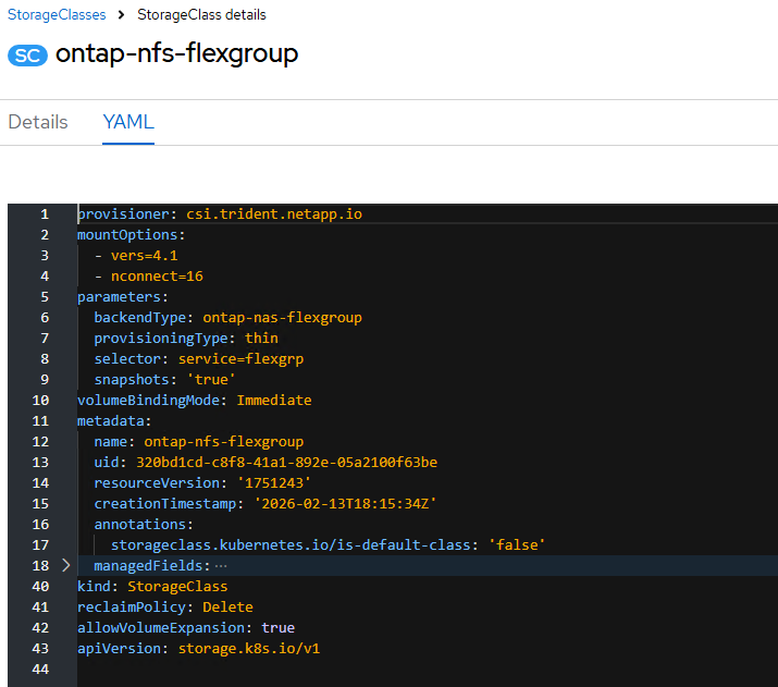
Note: The nconnect number sets the number of NFS sessions on the single mount point. 16 is the maximum value. Adjust this number downward if a large amount of regular NFS FlexGroup connections, which do not support NFS over RDMA and GDS, will be made.
Step 8. Create an ocp-nfs-rdma-flexgroup Trident backend by first creating the following .yaml file:
cat backend_NFS_rdma_flexgroup.yaml
---
version: 1
storageDriverName: ontap-nas-flexgroup
backendName: ocp-nfs-rdma-flexgroup
managementLIF: 10.102.2.52
dataLIF: 192.168.52.51
svm: AA02-OCP-RDMA-SVM
username: vsadmin
password: H1ghV0lt
useREST: true
defaults:
spaceReserve: none
exportPolicy: default
snapshotPolicy: default
snapshotReserve: '0'
nameTemplate: "{{.config.StoragePrefix}}_{{.config.BackendName}}_{{.volume.Namespace}}_{{.volume.RequestName}}"
labels:
service: "rdma"
perf: "standard"
Step 9. Add the backend to OpenShift.
tridentctl -n trident create backend -f backend_NFS_rdma_flexgroup.yaml
tridentctl -n trident get backend
Step 10. Create an ocp-nfs-rdma-flexgroup storage class by first creating the following .yaml file:
cat storage-class-ontap-nfs-rdma-flexgroup.yaml
---
apiVersion: storage.k8s.io/v1
kind: StorageClass
metadata:
name: ontap-nfs-rdma-flexgroup
annotations:
storageclass.kubernetes.io/is-default-class: "false"
provisioner: csi.trident.netapp.io
parameters:
backendType: "ontap-nas-flexgroup"
selector: "service=rdma"
provisioningType: "thin"
snapshots: "true"
mountOptions: ["vers=4.1","proto=rdma","max_connect=16","rsize=262144","wsize=262144","write=eager","hard","noatime","nodiratime"]
allowVolumeExpansion: true
Step 11. Create the storage class in OpenShift.
oc create -f storage-class-ontap-nfs-rdma-flexgroup.yaml
Step 12. Ensure that the NVIDIA Network Operator NicClusterPolicy has a status of State: ready. Select Operators > Installed Operators, the nvidia-network-operator project, NVIDIA Network Operator, and the NicClusterPolicy tab.
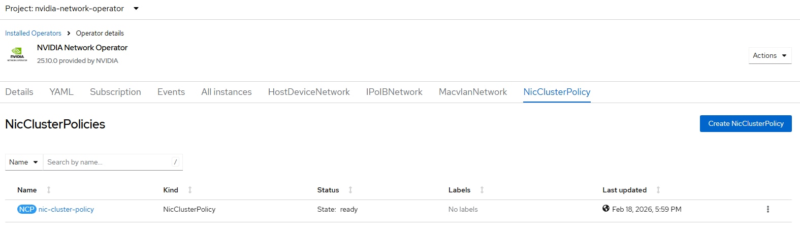
Step 13. Ensure that the NVIDIA GPU Operator ClusterPolicy has a status of State: ready. Select Operators > Installed Operators, the nvidia-gpu-operator project, NVIDIA GPU Operator, and the ClusterPolicy tab.

Procedure 4. Test NFS over RDMA and GDS
NFS over RDMA and GDS can be tested using a rdma-tools container publicly available on quay.io.
Step 1. Create two Persistent Volume Claims (PVCs) in the default namespace. In the OpenShift console, select Storage > PersistentVolumeClaims. Select the default Project. Click Create PersistentVolumeClaim > With Form and create the two PVCs as shown below.
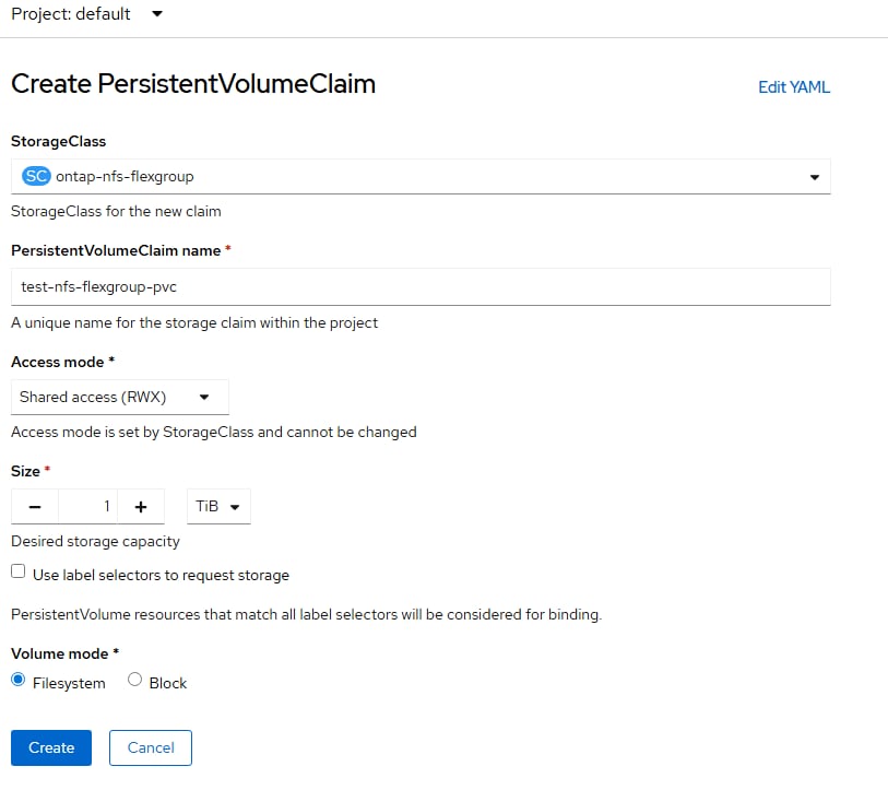
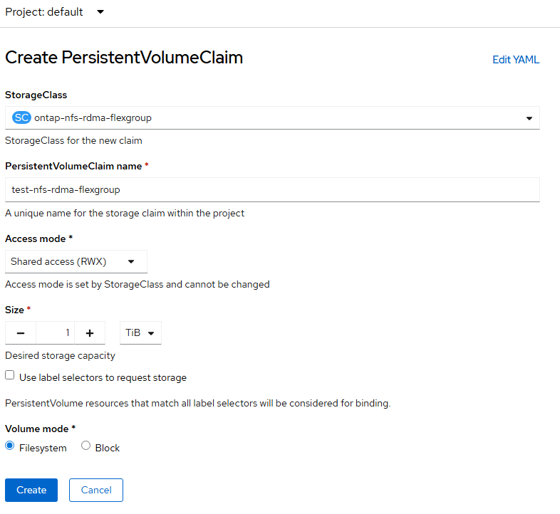
Step 2. In an nvidia-tools directory, create the following .yaml files:
cat nvidiatools-serviceaccount.yaml
apiVersion: v1
kind: ServiceAccount
metadata:
name: nvidiatools
namespace: default
cat nvidiatools-30-workload.yaml
apiVersion: v1
kind: Pod
metadata:
name: nvidiatools-30-workload
namespace: default
spec:
serviceAccountName: nvidiatools
nodeSelector:
kubernetes.io/hostname: worker-4
volumes:
- name: rdma-pv-storage
persistentVolumeClaim:
claimName: test-nfs-rdma-flexgroup
- name: nordma-pv-storage
persistentVolumeClaim:
claimName: test-nfs-flexgroup-pvc
containers:
- name: nvidiatools-30-workload
image: quay.io/wabouham/ecosys-nvidia/rdma-tools:0.0.3
imagePullPolicy: IfNotPresent
securityContext:
privileged: true
capabilities:
add: ["IPC_LOCK"]
resources:
limits:
nvidia.com/gpu: 1
requests:
nvidia.com/gpu: 1
volumeMounts:
- name: rdma-pv-storage
mountPath: /nfsfast
- name: nordma-pv-storage
mountPath: /nfsslow
Step 3. Bring the pod up with the following:
oc project default
oc create -f nvidiatools-serviceaccount.yaml
oc -n default adm policy add-scc-to-user privileged -z nvidiatools
oc create -f nvidiatools-30-workload.yaml
oc get pods #Until the pod is running. Then wait at least 5 minutes.
Step 4. Open a session in the pod.
oc exec -it nvidiatools-30-workload – bash
Step 5. Check the GDS configuration:
/usr/local/cuda-12.8/gds/tools/gdscheck -p
GDS release version: 1.13.1.3
nvidia_fs version: 2.26 libcufile version: 2.12
Platform: x86_64
============
ENVIRONMENT:
============
=====================
DRIVER CONFIGURATION:
=====================
NVMe P2PDMA : Unsupported
NVMe : Unsupported
NVMeOF : Unsupported
SCSI : Unsupported
ScaleFlux CSD : Unsupported
NVMesh : Unsupported
DDN EXAScaler : Unsupported
IBM Spectrum Scale : Unsupported
NFS : Supported
BeeGFS : Unsupported
WekaFS : Unsupported
Userspace RDMA : Unsupported
--Mellanox PeerDirect : Disabled
--rdma library : Not Loaded (libcufile_rdma.so)
--rdma devices : Not configured
--rdma_device_status : Up: 0 Down: 0
=====================
CUFILE CONFIGURATION:
=====================
properties.use_pci_p2pdma : false
properties.use_compat_mode : true
properties.force_compat_mode : false
properties.gds_rdma_write_support : true
properties.use_poll_mode : false
properties.poll_mode_max_size_kb : 4
properties.max_batch_io_size : 128
properties.max_batch_io_timeout_msecs : 5
properties.max_direct_io_size_kb : 16384
properties.max_device_cache_size_kb : 131072
properties.max_device_pinned_mem_size_kb : 33554432
properties.posix_pool_slab_size_kb : 4 1024 16384
properties.posix_pool_slab_count : 128 64 64
properties.rdma_peer_affinity_policy : RoundRobin
properties.rdma_dynamic_routing : 0
fs.generic.posix_unaligned_writes : false
fs.lustre.posix_gds_min_kb: 0
fs.beegfs.posix_gds_min_kb: 0
fs.weka.rdma_write_support: false
fs.gpfs.gds_write_support: false
fs.gpfs.gds_async_support: true
profile.nvtx : false
profile.cufile_stats : 0
miscellaneous.api_check_aggressive : false
execution.max_io_threads : 4
execution.max_io_queue_depth : 128
execution.parallel_io : true
execution.min_io_threshold_size_kb : 8192
execution.max_request_parallelism : 4
properties.force_odirect_mode : false
properties.prefer_iouring : false
=========
GPU INFO:
=========
GPU index 0 NVIDIA H200 bar:1 bar size (MiB):262144 supports GDS, IOMMU State: Disabled
==============
PLATFORM INFO:
==============
IOMMU: disabled
Nvidia Driver Info Status: Supported(Nvidia Open Driver Installed)
Cuda Driver Version Installed: 13000
Platform: UCSC-885A-M8-H26, Arch: x86_64(Linux 5.14.0-427.107.1.el9_4.x86_64)
Platform verification succeeded
Step 6. Verify the NFS over RDMA mount and the NFS over TCP mount:
mount | grep nfs
192.168.52.51:/trident_ocp_nfs_rdma_flexgroup_default_nfs_rdma_9c4f0 on /nfsfast type nfs4 (rw,noatime,nodiratime,vers=4.1,rsize=262144,wsize=262144,namlen=255,hard,proto=rdma,max_connect=16,port=20049,timeo=600,retrans=2,sec=sys,clientaddr=192.168.52.107,local_lock=none,write=eager,addr=192.168.52.51)
aa02-ocp-nfs-lif.aa02-ocp.flexpodb4.cisco.com:/trident_ocp_nfs_flexgroup_default_nfs_normal_77c94 on /nfsslow type nfs4 (rw,relatime,vers=4.1,rsize=262144,wsize=262144,namlen=255,hard,proto=tcp,nconnect=16,timeo=600,retrans=2,sec=sys,clientaddr=10.102.8.153,local_lock=none,addr=10.102.8.52)
Note: The IPs shown here are different because this was validated in a different lab.
Step 7. Run a sample write workload on each mount. The NFS over RDMA mount with use GDS (-x 0) and the NFS over TCP mount will use Storage to CPU to GPU (-x 2).
/usr/local/cuda-12.8/gds/tools/gdsio -D /nfsfast -d 0 -w 32 -s 50G -i 256K -x 0 -I 1 -T 120
IoType: WRITE XferType: GPUD Threads: 32 DataSetSize: 275860992/1677721600(KiB) IOSize: 256(KiB) Throughput: 2.184754 GiB/sec, Avg_Latency: 3540.411614 usecs ops: 1077582 total_time 120.417034 secs
/usr/local/cuda-12.8/gds/tools/gdsio -D /nfsslow -d 0 -w 32 -s 50G -i 256K -x 2 -I 1 -T 120
IoType: WRITE XferType: CPU_GPU Threads: 32 DataSetSize: 207761664/1677721600(KiB) IOSize: 256(KiB) Throughput: 1.651616 GiB/sec, Avg_Latency: 4742.871292 usecs ops: 811569 total_time 119.965479 secs
Step 8. Run sample read workloads on each mount.
/usr/local/cuda-12.8/gds/tools/gdsio -D /nfsfast -d 0 -w 32 -s 50G -i 256K -x 0 -I 0 -T 120
IoType: READ XferType: GPUD Threads: 32 DataSetSize: 2750820352/1677721600(KiB) IOSize: 256(KiB) Throughput: 21.922869 GiB/sec, Avg_Latency: 356.615790 usecs ops: 10745392 total_time 119.664387 secs
/usr/local/cuda-12.8/gds/tools/gdsio -D /nfsslow -d 0 -w 32 -s 50G -i 256K -x 2 -I 0 -T 120
IoType: READ XferType: CPU_GPU Threads: 32 DataSetSize: 2101642496/1677721600(KiB) IOSize: 256(KiB) Throughput: 16.797159 GiB/sec, Avg_Latency: 475.806746 usecs ops: 8209541 total_time 119.322703 secs
Note: For a full explanation of the gdsio command, see https://github.com/schmaustech/nvidia-tools-image. In both cases, transfers using GDS had higher throughput and lower latency.
Conclusion
FlexPod with Cisco AI POD is a comprehensive infrastructure solution for enterprises, designed to support their AI/ML journey and a range of AI workloads from training to fine-tuning to inferencing. The FlexPod with AI POD solution detailed in this document is a complete, integrated, and full-stack infrastructure specifically tailored for AI training and fine-tuning workloads. This architecture directly addresses unique AI requirements of enterprises, such as support for multiple smaller workloads with multi-tenancy, incremental scale with operational simplicity and consistency, and ease of integration into existing data center environments.
The FlexPod with Cisco AI POD solution for AI training and fine-tuning includes GPU-dense compute (UCS AI platforms), high-performance networking (Cisco Nexus), NetApp storage, and a robust AI software stack running on Linux or Kubernetes. Each AI POD is built, integrated, and validated in Cisco labs, backed by Cisco Validated Designs, and provides solution-level support through Cisco TAC. While focused on core infrastructure today, FlexPod with Cisco AI POD solutions are designed to evolve, supporting advanced security solutions (Cisco AI Defense, Hypershield) and new technology trends, thereby providing a future-ready platform.
The architectural approach of FlexPod with AI PODs ensures infrastructure is right-sized and can grow with enterprise adoption. This avoids upfront investments in large, potentially underutilized clusters—an important consideration given the rapid pace of technology innovation in the AI space. By leveraging the modularity and flexibility of Scale Units (for example, 32, 64, or 128 GPU clusters), combined with operational ease, design simplicity, and incremental scalability, Cisco AI PODs ensure consistency across all deployment vectors, even at scale.
By adopting FlexPod with Cisco AI PODs, enterprise organizations have a complete, pre-validated solution to meet their full spectrum of AI infra requirements and accelerate AI adoption in a secure manner. This approach reduces time-to-value, lowers total cost of ownership, and empowers enterprises to confidently operationalize AI initiatives that bring value to the business.
John George, Technical Marketing Engineer, Cisco Systems, Inc.
John has been involved in designing, developing, validating, and supporting the FlexPod Converged Infrastructure since it was developed more than 15 years ago. Before his role with FlexPod, he supported and administered a large worldwide training network and VPN infrastructure. John holds a master’s degree in Computer Engineering from Clemson University.
Abhinav Singh, Technical Marketing Engineer, Hybrid Cloud Infra & OEM Solutions, NetApp
Abhinav Singh is a Senior Technical Marketing Engineer for the Converged Infrastructure Solutions team at NetApp, who has over 15 years of expertise in Data Center Virtualization, Networking, and Storage. Abhinav specializes in designing, validating, implementing, and supporting Converged Infrastructure solutions, encompassing Data Center Virtualization, Hybrid Cloud, Cloud Native, Database, Storage, and Gen AI. Abhinav holds a bachelor's degree in electrical and electronics engineering.
Acknowledgements
For their support and contribution to the design, validation, and creation of this Cisco Validated Design, the authors would like to thank:
● Archana Sharma, Principal Technical Marketing Engineer, Cisco Systems, Inc.
● Anil Dhiman, Technical Marketing Engineer, Cisco Systems, Inc.
● Ramesh Isaac, Technical Marketing Engineer, Cisco Systems, Inc.
● Zaid McKie Krisberg, Tech Systems Engineering Technical Leader, Cisco Systems, Inc.
● Weiguo Sun, Principal Engineer, Cisco Systems, Inc.
● Nikhil Mitra, Site Reliability Engineering Technical Leader, Cisco Systems, Inc.
● Ben Schmaus, Red Hat Software
For comments and suggestions about this guide and related guides, email: custsatpms@cisco.com.
CVD Program
ALL DESIGNS, SPECIFICATIONS, STATEMENTS, INFORMATION, AND RECOMMENDATIONS (COLLECTIVELY, "DESIGNS") IN THIS MANUAL ARE PRESENTED "AS IS," WITH ALL FAULTS. CISCO AND ITS SUPPLIERS DISCLAIM ALL WARRANTIES, INCLUDING, WITHOUT LIMITATION, THE WARRANTY OF MERCHANTABILITY, FITNESS FOR A PARTICULAR PURPOSE AND NONINFRINGEMENT OR ARISING FROM A COURSE OF DEALING, USAGE, OR TRADE PRACTICE. IN NO EVENT SHALL CISCO OR ITS SUPPLIERS BE LIABLE FOR ANY INDIRECT, SPECIAL, CONSEQUENTIAL, OR INCIDENTAL DAMAGES, INCLUDING, WITHOUT LIMITATION, LOST PROFITS OR LOSS OR DAMAGE TO DATA ARISING OUT OF THE USE OR INABILITY TO USE THE DESIGNS, EVEN IF CISCO OR ITS SUPPLIERS HAVE BEEN ADVISED OF THE POSSIBILITY OF SUCH DAMAGES.
THE DESIGNS ARE SUBJECT TO CHANGE WITHOUT NOTICE. USERS ARE SOLELY RESPONSIBLE FOR THEIR APPLICATION OF THE DESIGNS. THE DESIGNS DO NOT CONSTITUTE THE TECHNICAL OR OTHER PROFESSIONAL ADVICE OF CISCO, ITS SUPPLIERS OR PARTNERS. USERS SHOULD CONSULT THEIR OWN TECHNICAL ADVISORS BEFORE IMPLE-MENTING THE DESIGNS. RESULTS MAY VARY DEPENDING ON FACTORS NOT TESTED BY CISCO.
CCDE, CCENT, Cisco Eos, Cisco Lumin, Cisco Nexus, Cisco StadiumVision, Cisco TelePresence, Cisco WebEx, the Cisco logo, DCE, and Welcome to the Human Network are trademarks; Changing the Way We Work, Live, Play, and Learn and Cisco Store are service marks; and Access Registrar, Aironet, AsyncOS, Bringing the Meeting To You, Catalyst, CCDA, CCDP, CCIE, CCIP, CCNA, CCNP, CCSP, CCVP, Cisco, the Cisco Certified Internetwork Expert logo, Cisco IOS, Cisco Press, Cisco Systems, Cisco Systems Capital, the Cisco Systems logo, Cisco Unified Computing System (Cisco UCS), Cisco UCS B-Series Blade Servers, Cisco UCS C-Series Rack Servers, Cisco UCS S-Series Storage Servers, Cisco UCS X-Series, Cisco UCS Manager, Cisco UCS Management Software, Cisco Unified Fabric, Cisco Application Centric Infrastructure, Cisco Nexus 9000 Series, Cisco Nexus 7000 Series. Cisco Prime Data Center Network Manager, Cisco NX-OS Software, Cisco MDS Series, Cisco Unity, Collaboration Without Limitation, EtherFast, EtherSwitch, Event Center, Fast Step, Follow Me Browsing, FormShare, GigaDrive, HomeLink, Internet Quotient, IOS, iPhone, iQuick Study, LightStream, Linksys, MediaTone, MeetingPlace, MeetingPlace Chime Sound, MGX, Networkers, Networking Academy, Network Registrar, PCNow, PIX, PowerPanels, ProConnect, ScriptShare, SenderBase, SMARTnet, Spectrum Expert, StackWise, The Fastest Way to Increase Your Internet Quotient, TransPath, WebEx, and the WebEx logo are registered trade-marks of Cisco Systems, Inc. and/or its affiliates in the United States and certain other countries. (LDW_P3)
All other trademarks mentioned in this document or website are the property of their respective owners. The use of the word partner does not imply a partnership relationship between Cisco and any other company. (0809R)