FlexPod Datacenter Base Configuration using IaC with Cisco IMM and NetApp ONTAP Deployment Guide
Available Languages
Bias-Free Language
The documentation set for this product strives to use bias-free language. For the purposes of this documentation set, bias-free is defined as language that does not imply discrimination based on age, disability, gender, racial identity, ethnic identity, sexual orientation, socioeconomic status, and intersectionality. Exceptions may be present in the documentation due to language that is hardcoded in the user interfaces of the product software, language used based on RFP documentation, or language that is used by a referenced third-party product. Learn more about how Cisco is using Inclusive Language.
- US/Canada 800-553-2447
- Worldwide Support Phone Numbers
- All Tools
 Feedback
 Feedback
![]()
In partnership with:

About the Cisco Validated Design Program
The Cisco Validated Design (CVD) program consists of systems and solutions designed, tested, and documented to facilitate faster, more reliable, and more predictable customer deployments. For more information, go to: http://www.cisco.com/go/designzone.
The FlexPod Datacenter solution is a validated design for deploying Cisco and NetApp technologies and products to build shared private and public cloud infrastructure. Cisco and NetApp have partnered to deliver a series of FlexPod solutions that enable strategic data center platforms. The success of the FlexPod solution is driven through its ability to evolve and incorporate both technology and product innovations in the areas of management, compute, storage, and networking. This document explains the deployment details of the base configuration of FlexPod Datacenter, setting up a configuration where bare metal OS or hypervisors can be layered on as tenants to support applications. Some of the key advantages of FlexPod Datacenter Base Configuration are:
● Consistent FlexPod Base Configuration: having a FlexPod Datacenter Base Configuration provides a consistent configuration that one or more of any bare metal OS or hypervisors can be layered on in a secure way to support one or more applications.
● Simpler and programmable infrastructure: the entire configuration can be configured using infrastructure as code delivered using Ansible.
● End-to-End 100Gbps Ethernet: utilizing the 5th Generation Cisco UCS VICs, the 5th Generation Cisco UCS 6536 Fabric Interconnects, and the Cisco UCSX-I-9108-100G Intelligent Fabric Module to deliver 100Gbps Ethernet from the server through the network to the storage.
● End-to-End 32Gbps Fibre Channel: utilizing the 5th Generation Cisco UCS VICs, the 5th Generation Cisco UCS 6536 Fabric Interconnects, and the Cisco UCSX-I-9108-100G Intelligent Fabric Module to deliver 32Gbps Ethernet from the server (using 100Gbps FCoE) through the network to the storage.
● Built for investment protections: design ready for future technologies such as liquid cooling and high-Wattage CPUs; CXL-ready.
In addition to the FlexPod-specific hardware and software innovations, the integration of the Cisco Intersight cloud platform with NetApp Active IQ Unified Manager, and Cisco Nexus and MDS switches delivers monitoring, orchestration, and workload optimization capabilities for different layers (storage and networking) of the FlexPod infrastructure. Implementation of this integration at this point in the deployment process would require Cisco Intersight Assist and NetApp Active IQ Unified Manager to be deployed outside of the FlexPod.
For information about the FlexPod design and deployment details, including the configuration of various elements of design and associated best practices, refer to Cisco Validated Designs for FlexPod, here: https://www.cisco.com/c/en/us/solutions/design-zone/data-center-design-guides/flexpod-design-guides.html.
Solution Overview
This chapter contains the following:
● Audience
The intended audience of this document includes but is not limited to IT architects, sales engineers, field consultants, professional services, IT managers, partner engineering, and customers who want to take advantage of an infrastructure built to deliver IT efficiency and enable IT innovation.
This document provides deployment guidance around bringing up the base FlexPod Datacenter infrastructure. The base configuration involves basic configuration that connects the FlexPod devices to the network, then configuring the base network configuration of each component, preparing the FlexPod for layering on bare metal OS, hypervisors, and applications in a multi-tenant way. This document introduces various design elements and explains various considerations and best practices for a successful deployment.
The following design elements distinguish this version of FlexPod from previous models:
● Configuration of only the base FlexPod, which mainly involves connecting the FlexPod devices to the network, then configuring the base network configuration of each component.
● All future FlexPod solution documents will refer to this document for a consistent base setup and then layer on the solution bare metal OS, hypervisor, and/or applications in a multi-tenant fashion.
Deployment Hardware and Software
This chapter contains the following:
● Ansible Automation Workflow and Solution Deployment
The FlexPod Datacenter with Cisco UCS and Cisco Intersight meets the following general design requirements:
● Resilient design across all layers of the infrastructure with no single point of failure
● Scalable design with the flexibility to add compute capacity, storage, or network bandwidth as needed
● Modular design that can be replicated to expand and grow as the needs of the business grow
● Flexible design that can support different models of various components with ease
● Simplified design with ability to integrate and automate with external automation tools
● Cloud-enabled design which can be configured, managed, and orchestrated from the cloud using GUI or APIs
To deliver a solution which meets all these design requirements, various solution components are connected and configured as explained in the following sections.
The FlexPod Datacenter base configuration is built using the following hardware components:
● Cisco UCS X9508 Chassis with Cisco UCSX-I-9108-100G intelligent fabric modules (IFMs) and up to eight Cisco UCS X210C Compute Nodes
● Fifth-generation Cisco UCS 6536 Fabric Interconnects to support 100GbE, 25GbE, and 32GFC connectivity from various components
● Cisco UCS C-Series M7 rack mount servers
● High-speed Cisco NX-OS-based Nexus 93600CD-GX switching design to support 100GE and 400GE connectivity
● NetApp AFF C800 end-to-end NVMe storage with 25G or 100G Ethernet and (optional) 32G Fibre Channel connectivity
● Cisco MDS 9132T* switches to support Fibre Channel storage configuration
Note: * Cisco MDS 9132T and FC connectivity is not needed when implementing IP-based connectivity design supporting iSCSI boot from SAN, NFS, and NVMe-TCP.
The software components of this solution consist of:
● Cisco Intersight to deploy, maintain, and support the Cisco UCS server components
● Cisco Intersight SaaS platform to maintain and support the FlexPod components
● Cisco Intersight Assist Virtual Appliance to help connect NetApp ONTAP and Cisco Nexus and MDS switches with Cisco Intersight
● NetApp Active IQ Unified Manager to monitor and manage the storage and for NetApp ONTAP integration with Cisco Intersight
FlexPod Datacenter for IP-based Storage Access
Figure 1 shows various hardware components and the network connections for the IP-based FlexPod design.

The reference hardware configuration includes:
● Two Cisco Nexus 93600CD-GX Switches in Cisco NX-OS mode provide the switching fabric. Other Cisco Nexus Switches are also supported.
● Two Cisco UCS 6536 Fabric Interconnects (FI) provide the chassis connectivity. Two 100 Gigabit Ethernet ports from each FI, configured as a Port-Channel, are connected to each Nexus 93600CD-GX. 25 Gigabit Ethernet connectivity is also supported as well as earlier versions of the Cisco UCS FI.
● One Cisco UCS X9508 Chassis connects to fabric interconnects using Cisco UCS UCSX-I-9108-100G IFMs, where four 100 Gigabit Ethernet ports are used on each IOM to connect to the appropriate FI. If additional bandwidth is required, all eight 100G ports can be utilized. The Cisco UCS UCSX-I-9108-25G IFM is also supported with 25 Gigabit Ethernet Connectivity.
● One NetApp AFF C800 HA pair connects to the Cisco Nexus 93600CD-GX Switches using two 100 GE ports from each controller configured as a Port-Channel. 25 Gigabit Ethernet connectivity is also supported as well as other NetApp AFF, ASA, and FAS storage controllers.
● One Cisco UCS C240 M7 rack mount server connects to the Fabric Interconnects using two 100 GE ports per server.
● One Cisco UCS C220 M7 rack mount server connects to the Fabric Interconnects using four 25 GE ports per server via breakout.
FlexPod Datacenter for FC-based Storage Access
Figure 2 shows various hardware components and the network connections for the FC-based FlexPod design.
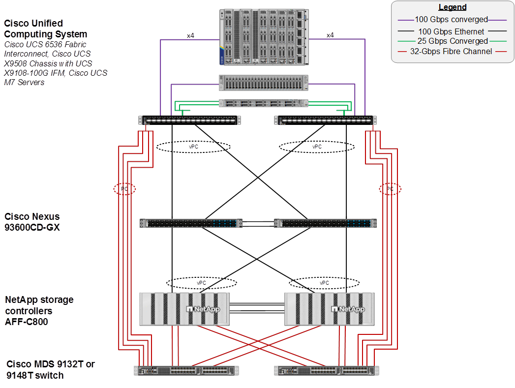
The reference hardware configuration includes:
● Two Cisco Nexus 93600CD-GX Switches in Cisco NX-OS mode provide the switching fabric. Other Cisco Nexus Switches are also supported.
● Two Cisco UCS 6536 Fabric Interconnects (FI) provide the chassis connectivity. Two 100 Gigabit Ethernet ports from each FI, configured as a Port-Channel, are connected to each Cisco Nexus 93600CD-GX. Four FC ports are connected to the Cisco MDS 9132T switches using 32-Gbps Fibre Channel connections via breakout configured as a single port channel for SAN connectivity. 25 Gigabit Ethernet connectivity and 16-Gbps Fibre Chanel connectivity is also supported as well as earlier versions of the Cisco UCS FI.
● One Cisco UCS X9508 Chassis connects to fabric interconnects using Cisco UCS UCSX-I-9108-100G IFMs, where four 100 Gigabit Ethernet ports are used on each IOM to connect to the appropriate FI. If additional bandwidth is required, all eight 100G ports can be utilized. The chassis to fabric interconnect connections are converged and carry both Ethernet and Fibre Channel over Ethernet (FCoE). The Cisco UCS UCSX-I-9108-25G IFM is also supported with 25 Gigabit Ethernet and FCoE Connectivity.
● One NetApp AFF C800 HA pair connects to the Cisco Nexus 93600CD-GX Switches using two 100 GE ports from each controller configured as a Port-Channel. Two 32Gbps FC ports from each controller are connected to each Cisco MDS 9132T for SAN connectivity. 25 Gigabit Ethernet and 16-Gbps Fibre Channel connectivity is also supported as well as other NetApp AFF, ASA, and FAS storage controllers.
● One Cisco UCS C240 M7 Rack Mount Server connects to the Fabric Interconnects using two 100 GE ports per server. These connections are also converged and carry both Ethernet and FCoE.
● One Cisco UCS C220 M7 Rack Mount Server connects to the Fabric Interconnects using four 25 GE ports per server. These connections are also converged and carry both Ethernet and FCoE.
Note: The NetApp storage controller and disk shelves should be connected according to best practices for the specific storage controller and disk shelves. For disk shelf cabling, refer to NetApp Support: https://docs.netapp.com/us-en/ontap-systems/index.html
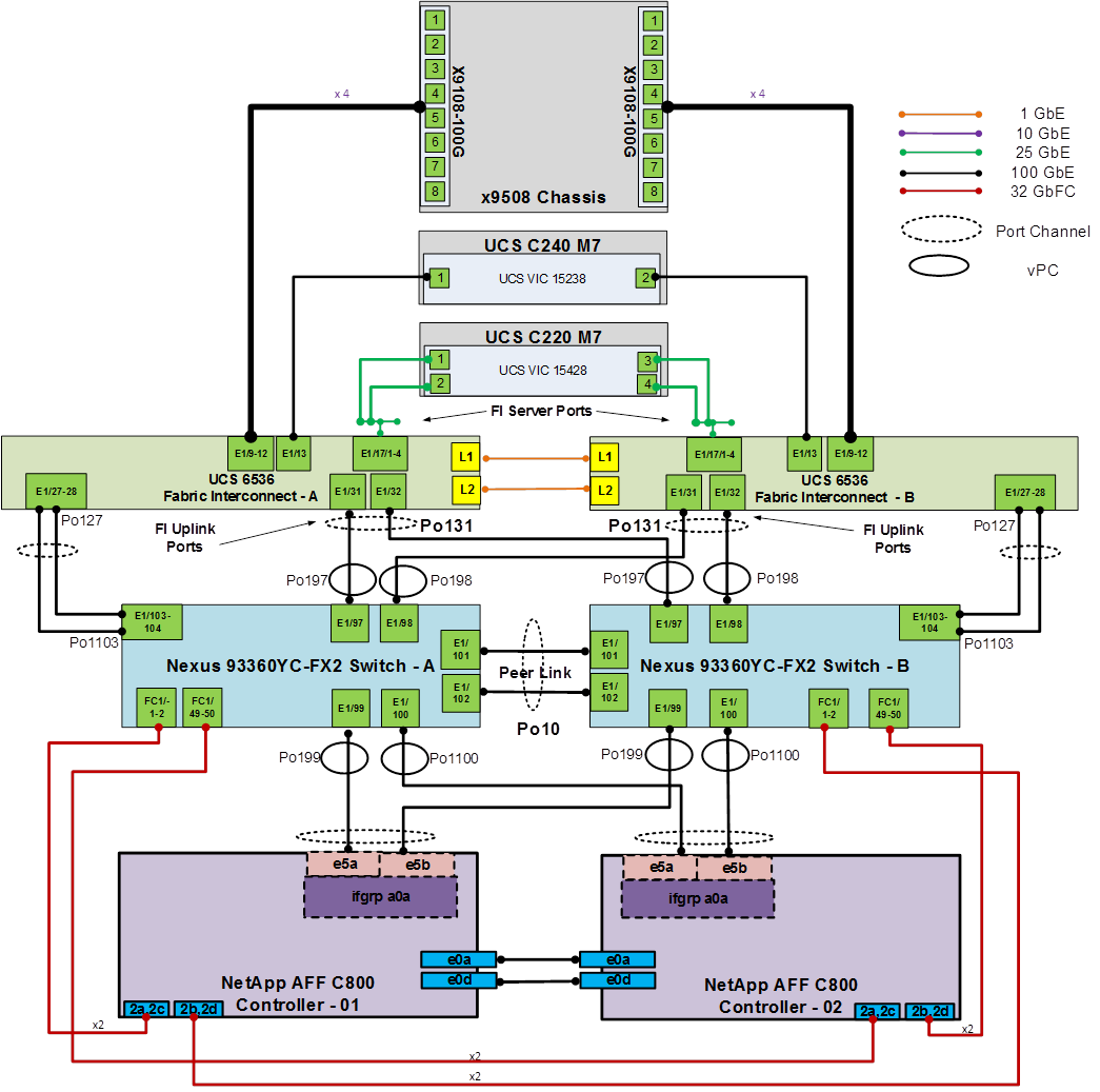
FlexPod Datacenter for FC-based Storage Access with Nexus SAN Switching
Figure 3 shows various hardware components and the network connections for the FC-based FlexPod design.
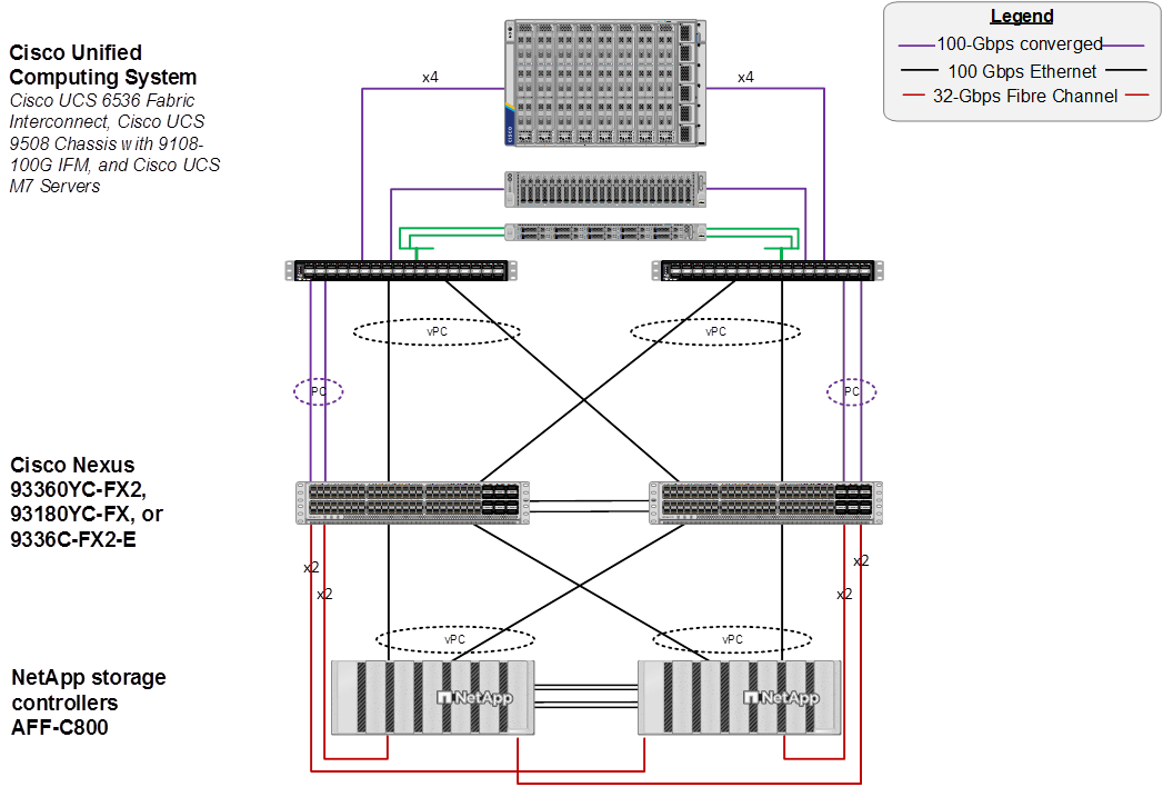
The reference hardware configuration includes:
● Two Cisco Nexus 93180YC-FX, 93360YC-FX2, or 9336C-FX2-E Switches in Cisco NX-OS mode provide the switching fabric for both LAN and SAN.
● Two Cisco UCS 6536 Fabric Interconnects (FI) provide the chassis connectivity. Two 100 Gigabit Ethernet ports from each FI, configured as a Port-Channel, are connected to each Nexus switch. Two 100G FCoE ports are connected to the Cisco Nexus switches configured as a single Ethernet port channel for SAN connectivity. 25 Gigabit Ethernet connectivity is also supported as well as earlier versions of the Cisco UCS FI.
● One Cisco UCS X9508 Chassis connects to fabric interconnects using Cisco UCS UCSX-I-9108-100G IFMs, where four 100 Gigabit Ethernet ports are used on each IOM to connect to the appropriate FI. If additional bandwidth is required, all eight 100G ports can be utilized. The chassis to fabric interconnect connections are converged and carry both Ethernet and Fibre Channel over Ethernet (FCoE). The Cisco UCS UCSX-I-9108-25G IFM is also supported with 25 Gigabit Ethernet and FCoE Connectivity.
● One NetApp AFF C800 HA pair connects to the Cisco Nexus Switches using two 100 GE ports from each controller configured as a Port-Channel. Two 32Gbps FC ports from each controller are connected to each Cisco Nexus switch for SAN connectivity (Cisco Nexus 9336C-FX2-E using breakout). 25 Gigabit Ethernet and 16-Gbps Fibre Channel connectivity is also supported as well as other NetApp AFF, ASA, and FAS storage controllers.
● One Cisco UCS C220 M7 Rack Mount Server connects to the Fabric Interconnects using two 100 GE ports per server. These connections are also converged and carry both Ethernet and FCoE.
● One Cisco UCS C220 M7 Rack Mount Server connects to the Fabric Interconnects four 25 GE ports per server. These connections are also converged and carry both Ethernet and FCoE.
Note: The NetApp storage controller and disk shelves should be connected according to best practices for the specific storage controller and disk shelves. For disk shelf cabling, refer to NetApp Support: https://docs.netapp.com/us-en/ontap-systems/index.html
Note: The Cisco UCS S9108 FI (Cisco UCS X-Series Direct) is now supported for this FlexPod configuration. The Cisco UCS S9108 is a standard FI that plugs into the Cisco UCS X9508 chassis and has 8-100G ports with specific rules for the ports. All UCS IMM UCS Domain polices can be applied to the S9108 in the same way as all other FIs.
VLAN Configuration
VLAN 1020 allows you to manage and access out-of-band management interfaces of various devices.
Table 1 lists VLANs configured for setting up the FlexPod environment along with their usage.
| VLAN ID |
Name |
Usage |
IP Subnet used in this deployment |
| 2 |
Native-VLAN |
Use VLAN 2 as native VLAN instead of default VLAN (1). |
|
| 1020 |
OOB-MGMT-VLAN |
Out-of-band management VLAN to connect management ports for various devices |
10.102.0.0/24; GW: 10.102.0.254 |
Table 2 lists the VMs or bare metal servers necessary for deployment as outlined in this document. Since FlexPod Base only sets up the networking components of the FlexPod with the OOB-MGMT-VLAN, if these are virtual machines, they are provisioned outside of the FlexPod environment in a management pod on the hypervisor of choice. These machines do need Layer 3 access to the OOB-MGMT-VLAN subnet.
Table 2. Virtual Machines or Bare Metal Servers
| Virtual Machine Description |
VLAN |
IP Address |
Comments |
| FlexPod AD1 |
1021 |
10.102.1.151 |
Hosted on pre-existing management infrastructure |
| FlexPod AD2 |
1021 |
10.102.1.152 |
Hosted on pre-existing management infrastructure |
| FlexPod Ansible |
1021 |
10.102.1.14 |
Hosted on pre-existing management infrastructure |
| NetApp Active IQ Unified Manager |
1021 |
10.102.1.97 |
Hosted on pre-existing management infrastructure |
| Cisco Intersight Assist |
1021 |
10.102.1.96 |
Hosted on pre-existing management infrastructure |
| Nexus Dashboard Fabric Controller (NDFC)-SAN |
1021 and 1020 |
10.102.1.21 |
Hosted on a separate server on pre-existing management infrastructure |
Table 3 lists the software revisions for various components of the solution.
| Layer |
Device |
Image Bundle |
Comments |
| Compute |
Cisco UCS Fabric Interconnect |
Suggested Release |
Cisco UCS S9108, 6454, 64108 also supported |
| Network |
Cisco Nexus 93600CD-GX NX-OS |
10.4(4)M |
Any Cisco Nexus 9300-Series Supported |
| Cisco MDS 9132T |
9.4(2a) |
Requires SMART Licensing – Any MDS 9100 Series supported |
|
| Storage |
NetApp AFF C800 |
ONTAP 9.16.1 |
Latest patch release – NetApp AFF, ASA, and FAS supported |
| Software |
Cisco Intersight Assist Appliance |
1.1.1-0 |
|
| NetApp Active IQ Unified Manager |
9.16 |
|
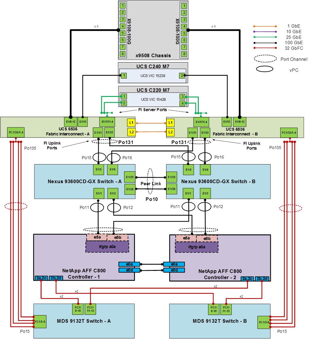
The information in this section is provided as a reference for cabling the physical equipment in a FlexPod environment. To simplify cabling requirements, a cabling diagram was used.
The cabling diagram in this section contains the details for the prescribed and supported configuration of the NetApp AFF C800 running NetApp ONTAP 9.16.1.
Note: For any modifications of this prescribed architecture, consult the NetApp Interoperability Matrix Tool (IMT).
Note: This document assumes that out-of-band management ports are plugged into an existing management infrastructure at the deployment site. These interfaces will be used in various configuration steps.
Note: Be sure to use the cabling directions in this section as a guide.
The NetApp storage controller and disk shelves should be connected according to best practices for the specific storage controller and disk shelves. For disk shelf cabling, refer to NetApp Support.
Figure 4 details the cable connections used in the validation lab for the FlexPod topology based on the Cisco UCS 6536 fabric interconnects. Four 32Gb uplinks connect as port-channels from each Cisco UCS Fabric Interconnect to the MDS switches, and a total of eight 32Gb links connect the MDS switches to the NetApp AFF controllers. Also, two 100Gb links connect each Cisco UCS Fabric Interconnect to the Cisco Nexus Switches and each NetApp AFF controller to the Cisco Nexus Switches. Additional 1Gb management connections will be needed for an out-of-band network switch that sits apart from the FlexPod infrastructure. Each Cisco UCS fabric interconnect and Cisco Nexus switch is connected to the out-of-band network switch, and each AFF controller has a connection to the out-of-band network switch. Layer 3 network connectivity is required between the Out-of-Band (OOB) and In-Band (IB) Management Subnets. This cabling diagram includes both the FC-boot and iSCSI-boot configurations.
Ansible Automation Workflow and Solution Deployment
The Ansible automated FlexPod solution uses a management workstation (control machine) to run Ansible playbooks to configure Cisco Nexus, NetApp ONTAP Storage, Cisco UCS, and Cisco MDS.
Figure 5 illustrates the FlexPod solution implementation workflow which is explained in the following sections. The FlexPod infrastructure layers are first configured in the order illustrated.

Prerequisites
Setting up the solution begins with a management workstation or VM that has access to the Internet and with a working installation of Ansible. The management workstation commonly runs a variant of Linux or MacOS for ease of use with these command-line-based tools. Instructions for installing the workstation are not included in this document, but basic installation and configuration of Ansible is explained. A guide for getting started with Ansible can be found here: https://docs.ansible.com/ansible_community.html
● To use the Ansible playbooks demonstrated in this document, the management workstation must also have a working installation of Git and access to the Cisco DevNet public GitHub repository. The Ansible playbooks used in this document are cloned from the public repositories, located at the following links:
◦ Cisco DevNet: https://developer.cisco.com/codeexchange/github/repo/ucs-compute-solutions/FlexPod-Base-IMM
◦ GitHub repository: https://github.com/ucs-compute-solutions/FlexPod-Base-IMM
● The Cisco Nexus and MDS Switches, NetApp Storage, and Cisco UCS must be physically racked, cabled, powered, and configured with management IP addresses before the Ansible-based installation procedure can begin as shown in the cabling diagram (Figure 4). If necessary, upgrade the Cisco Nexus Switches to release 10.4(4)M, and the Cisco MDS Switches to release 9.4(2a).
● Before running each Ansible Playbook to setup the Network, Storage, and Cisco UCS, various variables must be updated based on the customers environment and specific implementation.
● Day 2 Configuration tasks can be performed manually or with Cisco Intersight Cloud Orchestrator (ICO).
Procedure 1. Prepare Management Workstation (Control Machine)
In this procedure, the installation steps are performed on either RHEL 9.5 or Rocky Linux 9.5 (install default Server with GUI and add XRDP and Visual Studio Code) management host to prepare the host for solution deployment to support the automation of Cisco UCS, Cisco Nexus, NetApp Storage, and Cisco MDS using Ansible Playbooks.
Note: The following steps were performed on both RHEL 9.5 and Rocky Linux 9.5 Virtual Machines as the admin user.
Step 1. Install Python 3.11.
sudo dnf install python3.11
Step 2. Install pip3.11.
curl https://bootstrap.pypa.io/get-pip.py -o get-pip.py
python3.11 get-pip.py
rm get-pip.py
Step 3. Install Ansible engine with Python 3.11.
python3.11 -m pip install --user ansible
Step 4. Configure Ansible to use python3.11.
echo [defaults] > ~/.ansible.cfg
echo interpreter_python=/usr/bin/python3.11 >> ~/.ansible.cfg
echo jinja2_native=True >> ~/.ansible.cfg
Step 5. Verify Ansible version to make sure it is release 2.9 or later.
ansible --version
ansible [core 2.18.2]
config file = /home/admin/.ansible.cfg
configured module search path = ['/home/admin/.ansible/plugins/modules', '/usr/share/ansible/plugins/modules']
ansible python module location = /home/admin/.local/lib/python3.11/site-packages/ansible
ansible collection location = /home/admin/.ansible/collections:/usr/share/ansible/collections
executable location = /home/admin/.local/bin/ansible
python version = 3.11.9 (main, Dec 9 2024, 00:00:00) [GCC 11.5.0 20240719 (Red Hat 11.5.0-2)] (/usr/bin/python3.11)
jinja version = 3.1.5
libyaml = True
Step 6. Install sshpass.
sudo dnf install sshpass
Step 7. Install git.
sudo dnf install git
Step 8. Install NetApp specific python modules.
pip3.11 install netapp-lib
Step 9. Install UCSM SDK.
pip3.11 install ucsmsdk
Note: This step and the collection installation below was put in just in case this Ansible machine will also be used with Cisco UCS Manager installations.
Step 10. Install requests.
pip3.11 install requests
Step 11. Install ansible-galaxy collections and other dependencies for Cisco Nexus (and MDS), NetApp ONTAP, and Cisco UCS as follows:
ansible-galaxy collection install cisco.ucs --force
ansible-galaxy collection install cisco.intersight --force
ansible-galaxy collection install cisco.nxos --force
pip3.11 install ansible-pylibssh
ansible-galaxy collection install netapp.ontap --force
Note: The cisco.nxos collection is used for both Cisco Nexus and Cisco MDS configuration.
Procedure 2. Clone GitHub Collection
Note: You need to use a GitHub repository from one public location; the first step in the process is to clone the GitHub collection named FlexPod-Base-IMM (https://github.com/ucs-compute-solutions/FlexPod-Base-IMM.git) to a new empty folder on the management workstation. Cloning the repository creates a local copy, which is then used to run the playbooks that have been created for this solution.
Step 1. From the management workstation, create a new folder for the project. The GitHub collection will be cloned in a new folder inside this one, named /home/admin/ansible.
Step 2. Open a command-line or console interface on the management workstation and change directories to the new folder just created.
Step 3. Clone the GitHub collection using the following command:
git clone https://github.com/ucs-compute-solutions/FlexPod-Base-IMM.git
Step 4. Change directories to the new folder named FlexPod-Base-IMM.
Network Switch Configuration
This chapter contains the following:
● Ansible Nexus Switch Configuration
This chapter provides a detailed procedure for configuring the Cisco Nexus 93600CD-GX switches for use in a FlexPod environment. The Cisco Nexus 93600CD-GX will be used for LAN switching in this solution.
Note: The following procedures describe how to configure the Cisco Nexus switches for use in a base FlexPod environment. This procedure assumes the use of Cisco Nexus 9000 10.4(4)M.
● If using the Cisco Nexus 93600CD-GX switches or other Cisco Nexus switches for both LAN and SAN switching, please refer to section FlexPod with Cisco Nexus 93360YC-FX2 SAN Switching Configuration in the Appendix.
● The following procedure includes the setup of NTP distribution on the mgmt0 port. NTP Distribution will be setup later in FlexPod tenant configuration documents for tenant in-band management VLANs. The interface-vlan feature and ntp commands are used to set this up.
● This procedure sets up and uplink virtual port channel (vPC) with the IB-MGMT and OOB-MGMT VLANs allowed.
● This validation assumes that both switches have been reset to factory defaults by using the “write erase” command followed by the “reload” command.
Follow the physical connectivity guidelines for FlexPod as explained in section FlexPod Cabling.
The following procedures describe this basic configuration of the Cisco Nexus switches for use in the FlexPod environment. This procedure assumes the use of Cisco Nexus 9000 10.4(4)M, the Cisco suggested Nexus switch release at the time of this validation.
Procedure 1. Set Up Initial Configuration from a serial console
Set up the initial configuration for the Cisco Nexus A switch on <nexus-A-hostname>.
Step 1. Configure the switch.
Note: On initial boot, the NX-OS setup automatically starts and attempts to enter Power on Auto Provisioning.
Abort Power On Auto Provisioning [yes - continue with normal setup, skip - bypass password and basic configuration, no - continue with Power On Auto Provisioning] (yes/skip/no)[no]: yes
Disabling POAP.......Disabling POAP
poap: Rolling back, please wait... (This may take 5-15 minutes)
---- System Admin Account Setup ----
Do you want to enforce secure password standard (yes/no) [y]: Enter
Enter the password for "admin": <password>
Confirm the password for "admin": <password>
Would you like to enter the basic configuration dialog (yes/no): yes
Create another login account (yes/no) [n]: Enter
Configure read-only SNMP community string (yes/no) [n]: Enter
Configure read-write SNMP community string (yes/no) [n]: Enter
Enter the switch name: <nexus-A-hostname>
Continue with Out-of-band (mgmt0) management configuration? (yes/no) [y]: Enter
Mgmt0 IPv4 address: <nexus-A-out_of_band_mgmt0-ip>
Mgmt0 IPv4 netmask: <nexus-A-mgmt0-netmask>
Configure the default gateway? (yes/no) [y]: Enter
IPv4 address of the default gateway: <nexus-A-mgmt0-gw>
Configure advanced IP options? (yes/no) [n]: Enter
Enable the telnet service? (yes/no) [n]: Enter
Enable the ssh service? (yes/no) [y]: Enter
Type of ssh key you would like to generate (dsa/rsa) [rsa]: Enter
Number of rsa key bits <1024-2048> [1024]: 2048
Configure the ntp server? (yes/no) [n]: Enter
Configure default interface layer (L3/L2) [L2]: Enter
Configure default switchport interface state (shut/noshut) [noshut]: shut
Enter basic FC configurations (yes/no) [n]: n
Configure CoPP system profile (strict/moderate/lenient/dense) [strict]: Enter
Would you like to edit the configuration? (yes/no) [n]: Enter
Note: RHEL and Rocky Linux 9.5 requires a 2048-bit RSA key.
Step 2. Review the configuration summary before enabling the configuration.
Use this configuration and save it? (yes/no) [y]: Enter
Step 3. To set up the initial configuration of the Cisco Nexus B switch, repeat steps 1 and 2 with the appropriate host and IP address information.
Ansible Nexus Switch Configuration
Procedure 1. Configure the Cisco Nexus switches from the management workstation
Step 1. Add Nexus switch ssh keys to /home/admin/.ssh/known_hosts. Adjust known_hosts as necessary if errors occur.
ssh admin@<nexus-A-mgmt0-ip>
exit
ssh admin@<nexus-B-mgmt0-ip>
exit
Step 2. Edit the following variable files to ensure proper Cisco Nexus variables are entered:
● FlexPod-Base-IMM/group_vars/all.yml
● FlexPod-Base-IMM/group_vars/secrets.yml
● FlexPod-Base-IMM/group_vars/nexus.yml
● FlexPod-Base-IMM/inventory
● FlexPod-Base-IMM/host_vars/n9kA.yml
● FlexPod-Base-IMM/host_vars/n9kB.yml
Note: Switch configuration can be done one switch at a time by commenting one switch out in inventory and running the playbook. This may need to be done if the switches are shared with other FlexPods, and additional configuration needs to be added between playbook runs.
Step 3. From FlexPod-Base-IMM, run the Setup_Nexus.yml Ansible playbook.
ansible-playbook ./Setup_Nexus.yml -i inventory
NetApp ONTAP Storage Configuration
This chapter contains the following:
See the following section (NetApp Hardware Universe) for planning the physical location of the storage systems:
● Site Preparation
● System Connectivity Requirements
● Circuit Breaker, Power Outlet Balancing, System Cabinet Power Cord Plugs, and Console Pinout Requirements
● AFF Series Systems
To confirm that the hardware and software components that you would like to use are supported with the version of ONTAP that you plan to install, follow these steps at the NetApp Support site.
Procedure 1. Confirm hardware and software components
Step 1. Access the HWU application to view the System Configuration guides. Click the Products tab to select the Platforms menu to view the compatibility between different versions of the ONTAP software and the NetApp storage appliances with your desired specifications.
Step 2. Alternatively, to compare components by storage appliance, click Utilities and select Compare Storage Systems.
Follow the physical installation procedures for the controllers found here: https://docs.netapp.com/us-en/ontap-systems/index.html.
NetApp storage systems support a wide variety of disk shelves and disk drives. The complete list of disk shelves that are supported by the NetApp AFF C800 is available at the NetApp Support site.
When using SAS disk shelves with NetApp storage controllers, go to: https://docs.netapp.com/us-en/ontap-systems/sas3/install-new-system.html for proper cabling guidelines.
When using NVMe drive shelves with NetApp storage controllers, go to: https://docs.netapp.com/us-en/ontap-systems/ns224/hot-add-shelf.html for installation and servicing guidelines.
Complete Configuration Worksheet
Before running the setup script, complete the Cluster setup worksheet in the NetApp ONTAP 9 Documentation Center. You must have access to the NetApp Support site to open the cluster setup worksheet.
Ansible NetApp ONTAP Storage Configuration
ONTAP Storage Configuration for a FlexPod Base is automated with Ansible. ONTAP Storage can be deployed via Ansible after the ONTAP Cluster setup is complete and the Cluster management network is configured.
A playbook by the name 'Setup_ONTAP.yml' is available at the root of this repository. It calls all the required roles to complete the setup of the ONTAP storage system for FlexPod Base setup.
Execute the playbook from the Ansible Control machine as an admin/ root user using the following command:
● After setup of Cisco Nexus switches and bringing the NetApp storage cluster online: ansible-playbook -i inventory Setup_ONTAP.yml -t ontap_base_config
If you would like to run a part of the deployment, you may use the appropriate tag that accompanies each task in the role and run the playbook by running the following command:
ansible-playbook -i inventory Setup_ONTAP.yml -t <tag_name>
Before running the setup script, review the configuration worksheets in the Software setup section of the ONTAP 9 Documentation Center to learn about configuring ONTAP. Table 4 lists the information needed to configure two ONTAP nodes. Customize the cluster-detail values with the information applicable to your deployment.
Table 4. ONTAP Software Installation Prerequisites
| Cluster Detail |
Cluster Detail Value |
| Cluster node 01 IP address |
<node01-mgmt-ip> |
| Cluster node 01 netmask |
<node01-mgmt-mask> |
| Cluster node 01 gateway |
<node01-mgmt-gateway> |
| Cluster node 02 IP address |
<node02-mgmt-ip> |
| Cluster node 02 netmask |
<node02-mgmt-mask> |
| Cluster node 02 gateway |
<node02-mgmt-gateway> |
| ONTAP 9.16.1 URL (http server hosting ONTAP software) |
<url-boot-software> |
Procedure 1. Configure Node 01
Step 1. Connect to the storage system console port. You should see a Loader-A prompt. However, if the storage system is in a reboot loop, press Ctrl-C to exit the autoboot loop when the following message displays:
Starting AUTOBOOT press Ctrl-C to abort…
Step 2. Allow the system to boot up.
autoboot
Step 3. Press Ctrl-C when prompted.
Note: Use the latest NetApp ONTAP release. In this example, it is 9.16.1. If NetApp ONTAP 9.16.1 is not the version of the software being booted, continue with the following steps to install new software. If NetApp ONTAP 9.16.1 is the version being booted, select option 8 and y to reboot the node, then continue with section Set Up Node.
Step 4. To install new software, select option 7 from the menu.
Step 5. Enter y to continue the installation.
Step 6. Select e0M for the network port for the download.
Step 7. Enter n to skip the reboot.
Step 8. Select option 7 from the menu: Install new software first
Step 9. Enter y to continue the installation.
Step 10. Enter the IP address, netmask, and default gateway for e0M.
Enter the IP address for port e0M: <node01-mgmt-ip>
Enter the netmask for port e0M: <node01-mgmt-mask>
Enter the IP address of the default gateway: <node01-mgmt-gateway>
Step 11. Enter the URL where the software can be found.
Note: The e0M interface should be connected to the management network and the web server must be reachable (using ping) from node 01.
<url-boot-software>
Step 12. Press Enter for the user name, indicating no user name.
Step 13. Enter y to set the newly installed software as the default to be used for subsequent reboots.
Step 14. Enter y to reboot the node now.
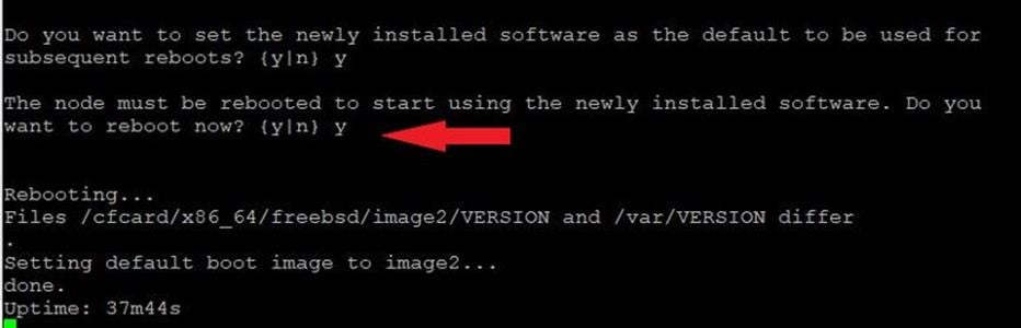
Note: When installing new software, the system might perform firmware upgrades to the BIOS and adapter cards, causing reboots and possible stops at the Loader-A prompt. If these actions occur, the system might deviate from this procedure.
Note: During the ONTAP installation a prompt to reboot the node requests a Y/N response.
Step 15. Press Ctrl-C when the following message displays:
Press Ctrl-C for Boot Menu
Step 16. Select option 4 for Clean Configuration and Initialize All Disks.
Step 17. Enter y to zero disks, reset config, and install a new file system.
Step 18. Enter yes to erase all the data on the disks.
Note: When initialization and creation of root aggregate is complete, the storage system reboots. You can continue with the configuration of node 02 while the initialization and creation of the root aggregate for node 01 is in progress. For more information about root aggregate and disk partitioning, please refer to the following NetApp ONTAP documentation on root-data partitioning: https://docs.netapp.com/us-en/ontap/concepts/root-data-partitioning-concept.html
Procedure 2. Configure Node 02
Step 1. Connect to the storage system console port. You should see a Loader-B prompt. However, if the storage system is in a reboot loop, press Ctrl-C to exit the autoboot loop when the following message displays:
Starting AUTOBOOT press Ctrl-C to abort…
Step 2. Allow the system to boot up.
autoboot
Step 3. Press Ctrl-C when prompted.
Note: If NetApp ONTAP 9.16.1 is not the version of the software being booted, continue with the following steps to install new software. If NetApp ONTAP 9.16.1 is the version being booted, select option 8 and y to reboot the node. Continue with section Set Up Node.
Step 4. To install new software, select option 7.
Step 5. Enter y to continue the installation.
Step 6. Select e0M for the network port you want to use for the download.
Step 7. Enter n to skip the reboot.
Step 8. Select option 7: Install new software first
Step 9. Enter y to continue the installation.
Step 10. Enter the IP address, netmask, and default gateway for e0M.
Enter the IP address for port e0M: <node02-mgmt-ip>
Enter the netmask for port e0M: <node02-mgmt-mask>
Enter the IP address of the default gateway: <node02-mgmt-gateway>
Step 11. Enter the URL where the software can be found.
Note: The web server must be reachable (ping) from node 02.
<url-boot-software>
Step 12. Press Enter for the username, indicating no username.
Step 13. Enter y to set the newly installed software as the default to be used for subsequent reboots.
Step 14. Enter y to reboot the node now.
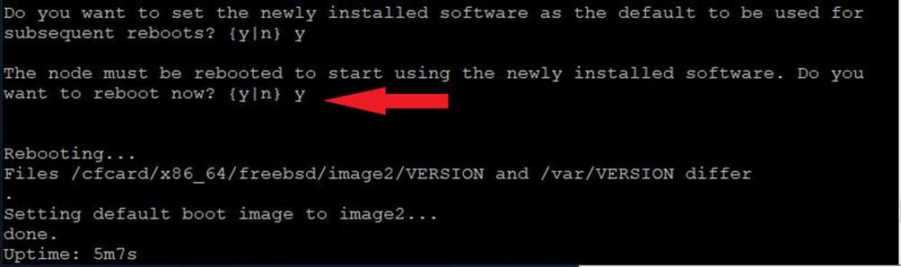
Note: When installing new software, the system might perform firmware upgrades to the BIOS and adapter cards, causing reboots and possible stops at the Loader-B prompt. If these actions occur, the system might deviate from this procedure.
Note: During the ONTAP installation a prompt to reboot the node requests a Y/N response.
Step 15. Press Ctrl-C when you see this message:
Press Ctrl-C for Boot Menu
Step 16. Select option 4 for Clean Configuration and Initialize All Disks.
Step 17. Enter y to zero disks, reset config, and install a new file system.
Step 18. Enter yes to erase all the data on the disks.
Note: When initialization and creation of root aggregate is complete, the storage system reboots. For more information about root aggregate and disk partitioning, please refer to the following ONTAP documentation on root-data partitioning. https://docs.netapp.com/us-en/ontap/concepts/root-data-partitioning-concept.html
Step 1. From a console port program attached to the storage controller A (node 01) console port, run the node setup script. This script appears when ONTAP 9.16.1 boots on the node for the first time.
Step 2. Follow the prompts to set up node 01.
Welcome to the cluster setup wizard.
You can enter the following commands at any time:
"help" or "?" - if you want to have a question clarified,
"back" - if you want to change previously answered questions, and
"exit" or "quit" - if you want to quit the setup wizard.
Any changes you made before quitting will be saved.
You can return to cluster setup at any time by typing “cluster setup”.
To accept a default or omit a question, do not enter a value.
This system will send event messages and weekly reports to NetApp Technical Support.
To disable this feature, enter "autosupport modify -support disable" within 24 hours.
Enabling AutoSupport can significantly speed problem determination and resolution should a problem occur on your system.
For further information on AutoSupport, see:
http://support.netapp.com/autosupport/
Type yes to confirm and continue {yes}: yes
Enter the node management interface port [e0M]: Enter
Enter the node management interface IP address: <node01-mgmt-ip>
Enter the node management interface netmask: <node01-mgmt-mask>
Enter the node management interface default gateway: <node01-mgmt-gateway>
A node management interface on port e0M with IP address <node01-mgmt-ip> has been created.
Use your web browser to complete cluster setup by accesing https://<node01-mgmt-ip>
Otherwise press Enter to complete cluster setup using the command line interface:
Step 3. Repeat Step 2 to set up node 02.
Step 4. To complete cluster setup using System Manager, open a web browser and navigate to https://<node01-mgmt-ip>.
Table 5. Cluster Create in ONTAP Prerequisites
| Cluster Detail |
Cluster Detail Value |
| Cluster name |
<clustername> |
| Cluster Admin SVM |
<cluster-adm-svm> |
| Infrastructure Data SVM |
<infra-data-svm> |
| ONTAP base license |
<cluster-base-license-key> |
| Cluster management IP address |
<clustermgmt-ip> |
| Cluster management netmask |
<clustermgmt-mask> |
| Cluster management gateway |
<clustermgmt-gateway> |
| Cluster node 01 IP address |
<node01-mgmt-ip> |
| Cluster node 01 netmask |
<node01-mgmt-mask> |
| Cluster node 01 gateway |
<node01-mgmt-gateway> |
| Cluster node 02 IP address |
<node02-mgmt-ip> |
| Cluster node 02 netmask |
<node02-mgmt-mask> |
| Cluster node 02 gateway |
<node02-mgmt-gateway> |
| Node 01 service processor IP address |
<node01-sp-ip> |
| Node 01 service processor network mask |
<node01-sp-mask> |
| Node 01 service processor gateway |
<node01-sp-gateway> |
| Node 02 service processor IP address |
<node02-sp-ip> |
| Node 02 service processor network mask |
<node02-sp-mask> |
| Node 02 service processor gateway |
<node02-sp-gateway> |
| Node 01 node name |
<st-node01> |
| Node 02 node name |
<st-node02> |
| DNS domain name |
<dns-domain-name> |
| DNS server IP address |
<dns-ip> |
| NTP server A IP address |
<switch-a-ntp-ip> |
| NTP server B IP address |
<switch-b-ntp-ip> |
| SNMPv3 User |
<snmp-v3-usr> |
| SNMPv3 Authentication Protocol |
<snmp-v3-auth-proto> |
| SNMPv3 Privacy Protocol |
<snmpv3-priv-proto> |
Note: Cluster setup can also be performed using the CLI. This document describes the cluster setup using the NetApp ONTAP System Manager guided setup.
Step 5. Complete the required information on the Initialize Storage System screen:
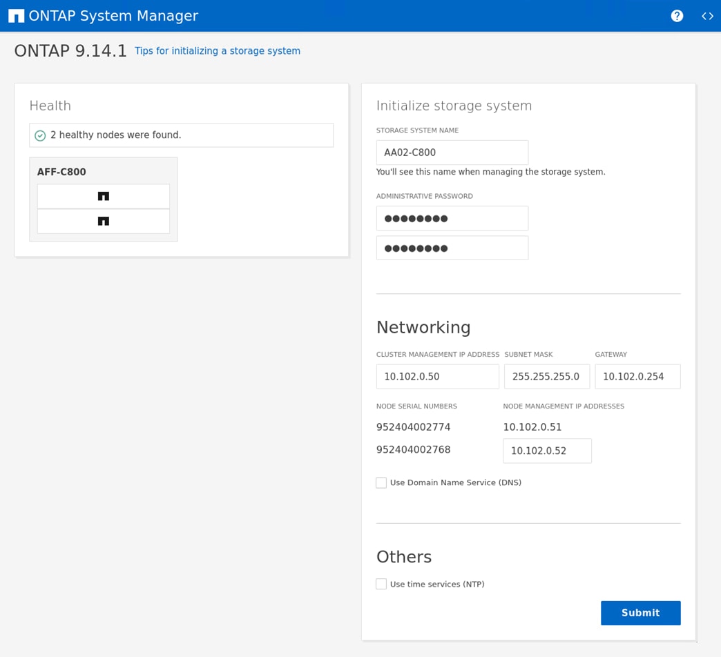
a. Enter the cluster name and administrator password.
b. Complete the Networking information for the cluster and each node.
Note: The screenshot shown above was from a different storage cluster with a different IP address range than what is shown in the rest of this document. This was because of controller availability for testing.
Note: Here, the DNS and NTP server manual configuration for the cluster is optional. Ansible scripts will configure the same when ONTAP playbook with the tag “ontap_base_config” is executed.
Note: The nodes should be discovered automatically; if they are not, refresh the browser page. By default, the cluster interfaces are created on all the new factory shipping storage controllers.
Note: If all the nodes are not discovered, then configure the cluster using the command line.
Note: The node management interface can be on the same subnet as the cluster management interface, or it can be on a different subnet. In this document, we assume that it is on the same subnet.
Step 6. Click Submit.
Note: A few minutes will pass while the cluster is configured. You can use Ansible scripts at this point to configure the ONTAP Storage Configuration via Ansible.
Procedure 4. Ansible ONTAP Storage Configuration – Base Config
Step 1. Edit the following variable files to ensure proper ONTAP Storage variables are entered:
● FlexPod-Base-IMM/group_vars/secrets.yml
● FlexPod-Base-IMM/inventory
● FlexPod-Base-IMM/group_vars/all.yml
● FlexPod-Base-IMM/group_vars/ontap
● FlexPod-Base-IMM/vars/ontap_main.yml
Step 2. From FlexPod-Base-IMM, run the Setup_ONTAP.yml Ansible playbook with the associated tag for this section:
ansible-playbook -i inventory Setup_ONTAP.yml -t ontap_base_config
Note: Use the -vvv tag to see detailed execution output log.
Cisco Intersight Managed Mode Configuration
This chapter contains the following:
● Set up Cisco Intersight Managed Mode on Cisco UCS Fabric Interconnects
● Set up Cisco Intersight Account
● Set up Cisco Intersight Licensing
● Set Up Cisco Intersight Resource Group
● Set Up Cisco Intersight Organization
● Claim Cisco UCS Fabric Interconnects in Cisco Intersight
● Verify Addition of Cisco UCS Fabric Interconnects to Cisco Intersight
● Upgrade Fabric Interconnect Firmware using Cisco Intersight
● Ansible Cisco UCS IMM Configuration
● Attach UCS Domain Profile to UCS Domain
● Verify Cisco UCS Domain Profile Deployment
● Create Chassis Profile Template (optional)
● Attach UCS Chassis Profile to Chassis
The Cisco Intersight platform is a management solution delivered as a service with embedded analytics for Cisco and third-party IT infrastructures. The Cisco Intersight Managed Mode (also referred to as Cisco IMM or Intersight Managed Mode) is an architecture that manages Cisco Unified Computing System (Cisco UCS) fabric interconnect–attached systems through a Redfish-based standard model. Cisco Intersight managed mode standardizes both policy and operation management for Cisco UCS C-Series M7 and Cisco UCS X210c M7 compute nodes used in this deployment guide.
Cisco UCS B-Series M6 servers, connected and managed through Cisco UCS FIs, are also supported by IMM. For a complete list of supported platforms, go to: https://www.cisco.com/c/en/us/td/docs/unified_computing/Intersight/b_Intersight_Managed_Mode_Configuration_Guide/b_intersight_managed_mode_guide_chapter_01010.html
Procedure 1. Set up Cisco Intersight Managed Mode on Cisco UCS Fabric Interconnects
The Cisco UCS fabric interconnects need to be set up to support Cisco Intersight Managed Mode. When converting an existing pair of Cisco UCS fabric interconnects from Cisco UCS Manager mode to Intersight Managed Mode (IMM), first erase the configuration and reboot your system.
Note: Converting fabric interconnects to Cisco Intersight managed mode is a disruptive process, and configuration information will be lost. You are encouraged to make a backup of their existing configuration.
Step 1. Configure Fabric Interconnect A (FI-A). On the Basic System Configuration Dialog screen, set the management mode to Intersight. The remaining settings are similar to those for the Cisco UCS Manager Managed mode (UCSM-Managed).
Cisco UCS Fabric Interconnect A
To configure the Cisco UCS for use in a FlexPod environment in IMM, follow these steps:
1. Connect to the console port on the first Cisco UCS fabric interconnect.
Enter the configuration method. (console/gui) ? console
Enter the management mode. (ucsm/intersight)? intersight
The Fabric interconnect will be configured in the intersight managed mode. Choose (y/n) to proceed: y
Enforce strong password? (y/n) [y]: Enter
Enter the password for "admin": <password>
Confirm the password for "admin": <password>
Enter the switch fabric (A/B) []: A
Enter the system name: <ucs-cluster-name>
Physical Switch Mgmt0 IP address : <ucsa-mgmt-ip>
Physical Switch Mgmt0 IPv4 netmask : <ucs-mgmt-mask>
IPv4 address of the default gateway : <ucs-mgmt-gateway>
DNS IP address : <dns-server-1-ip>
Configure the default domain name? (yes/no) [n]: y
Default domain name : <ad-dns-domain-name>
Following configurations will be applied:
Management Mode=intersight
Switch Fabric=A
System Name=<ucs-cluster-name>
Enforced Strong Password=yes
Physical Switch Mgmt0 IP Address=<ucsa-mgmt-ip>
Physical Switch Mgmt0 IP Netmask=<ucs-mgmt-mask>
Default Gateway=<ucs-mgmt-gateway>
DNS Server=<dns-server-1-ip>
Domain Name=<ad-dns-domain-name>
Apply and save the configuration (select 'no' if you want to re-enter)? (yes/no): yes
Step 2. After applying the settings, make sure you can ping the fabric interconnect management IP address. When Fabric Interconnect A is correctly set up and is available, Fabric Interconnect B will automatically discover Fabric Interconnect A during its setup process as shown in the next step. Wait until “Starting Intersight managed UCS Processes..” appears in the Cisco UCS Fabric Interconnect A window.
Step 3. Configure Fabric Interconnect B (FI-B). For the configuration method, select console. Fabric Interconnect B will detect the presence of Fabric Interconnect A and will prompt you to enter the admin password for Fabric Interconnect A. Provide the management IP address for Fabric Interconnect B and apply the configuration.
Cisco UCS Fabric Interconnect B
Enter the configuration method. (console/gui) ? console
Installer has detected the presence of a peer Fabric interconnect. This Fabric interconnect will be added to the cluster. Continue (y/n) ? y
Enter the admin password of the peer Fabric interconnect: <password>
Connecting to peer Fabric interconnect... done
Retrieving config from peer Fabric interconnect... done
Peer Fabric interconnect Mgmt0 IPv4 Address: <ucsa-mgmt-ip>
Peer Fabric interconnect Mgmt0 IPv4 Netmask: <ucs-mgmt-mask>
Peer FI is IPv4 Cluster enabled. Please Provide Local Fabric Interconnect Mgmt0 IPv4 Address
Physical Switch Mgmt0 IP address : <ucsb-mgmt-ip>
Local fabric interconnect model <fi-model>
Peer fabric interconnect is compatible with the local fabric interconnect. Continuing with the installer...
Apply and save the configuration (select 'no' if you want to re-enter)? (yes/no): yes
Procedure 2. Set up Cisco Intersight Account
Step 1. Go to https://intersight.com and click Create an account. Complete the log in process.
Step 2. Select the appropriate Region and click Next.
Step 3. Read and accept the license agreement. Click Next.
Step 4. Provide an Account Name and click Create.
With a successful creation of the Intersight account, the following page will be displayed:
Note: You can also choose to add the Cisco UCS FIs to an existing Cisco Intersight account.
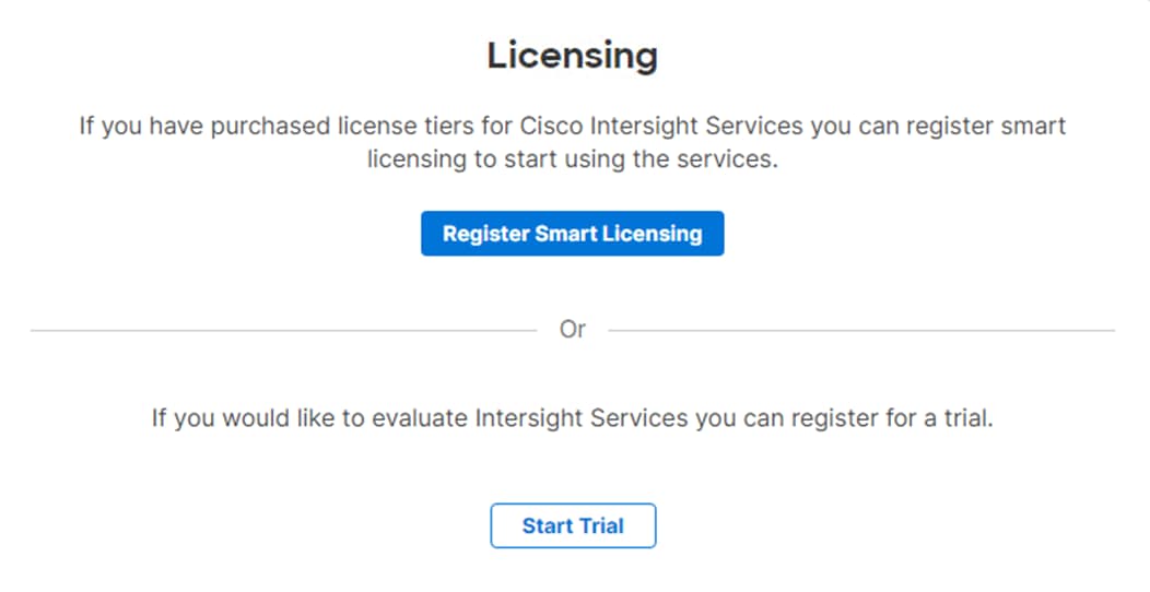
Procedure 3. Set up Cisco Intersight Licensing
Note: When setting up a new Cisco Intersight account (as explained in this document), the account needs to be enabled for Cisco Smart Software Licensing.
Step 1. Log into the Cisco Smart Licensing portal: https://software.cisco.com/software/smart-licensing/alerts.
Step 2. Verify that the correct virtual account is selected.
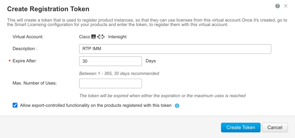
Step 3. Under Inventory > General, click New Token to generate a new token for product registration.
Step 4. Fill in the form and click Create Token. Copy this newly created token.
Step 5. In Cisco Intersight, if you created a new account, click Register Smart Licensing.
Step 6. Enter the copied token from the Cisco Smart Licensing portal. Click Next.
Step 7. With Enable Subscription Information selected, click Next. Click Allow.
Step 8. Select the products, you wish to enable (minimally Infrastructure Service). From the drop-down list select the licenses or your Default Tier (for example, Advantage for all).
Step 9. Select Set Default Tier to all existing servers.
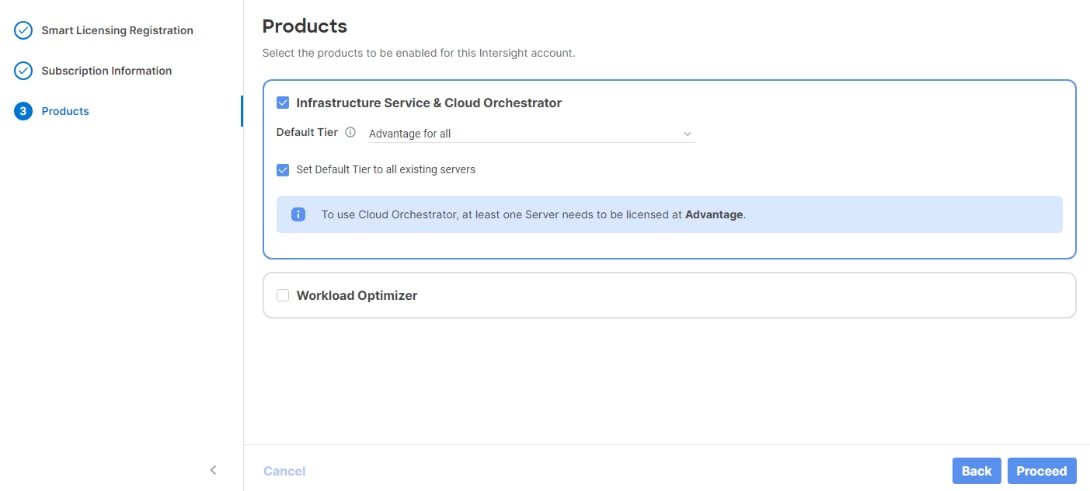
Step 10. Click Proceed then click Confirm.
Step 11. When the registration is successful, a Meet Intersight window displays. Click Let’s Go to review the latest Intersight features or click Skip.
Procedure 4. Set Up Cisco Intersight Resource Group
In this procedure, a Cisco Intersight resource group is created where resources such as targets will be logically grouped. In this deployment, a single resource group is created to host all the resources, but you can choose to create multiple resource groups for granular control of the resources.
Step 1. Log into Cisco Intersight.
Step 2. Expand System.
Step 3. Click Resource Groups.
Step 4. Click + Create Resource Group.
Step 5. Provide a name for the Resource Group (for example, AA02-rg).
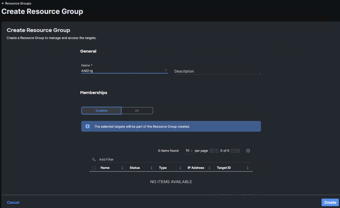
Step 6. Under Memberships, select Custom.
Step 7. Click Create.
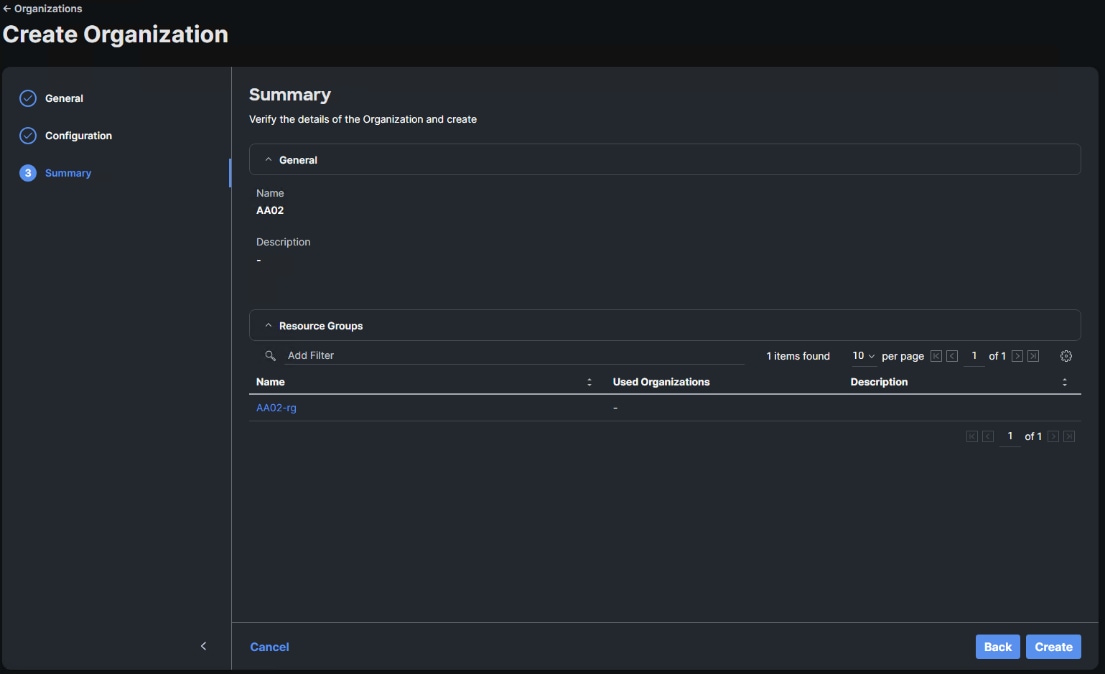
Procedure 5. Set Up Cisco Intersight Organization
In this procedure, an Intersight organization is created where all Cisco Intersight Managed Mode configurations including policies are defined.
Step 1. Log into the Cisco Intersight portal.
Step 2. Select System.
Step 3. Click Organizations.
Step 4. Click + Create Organization.
Step 5. Provide a name for the organization (for example, AA02). Optionally, select Share Resources with Other Organizations, and click Next.
Step 6. Select the Resource Group created in the last step (for example, AA02-rg) and click Next.
Step 7. Click Create.
Procedure 6. Claim Cisco UCS Fabric Interconnects in Cisco Intersight
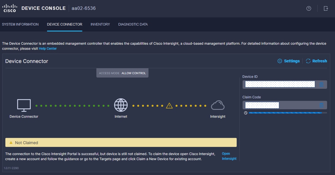
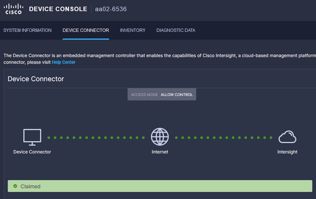
Make sure the initial configuration for the fabric interconnects has been completed. Log into the Fabric Interconnect A Device Console using a web browser to capture the Cisco Intersight connectivity information.
Step 1. Use the management IP address of Fabric Interconnect A to access the device from a web browser and the previously configured admin password to log into the device. Periodically, refresh the page until both FIs are visible.
Step 2. Under DEVICE CONNECTOR, the current device status will show “Not claimed.” Note or copy the Device ID and Claim Code information for claiming the device in Cisco Intersight.
Step 3. Log into Cisco Intersight.
Step 4. Select System. Click Targets.
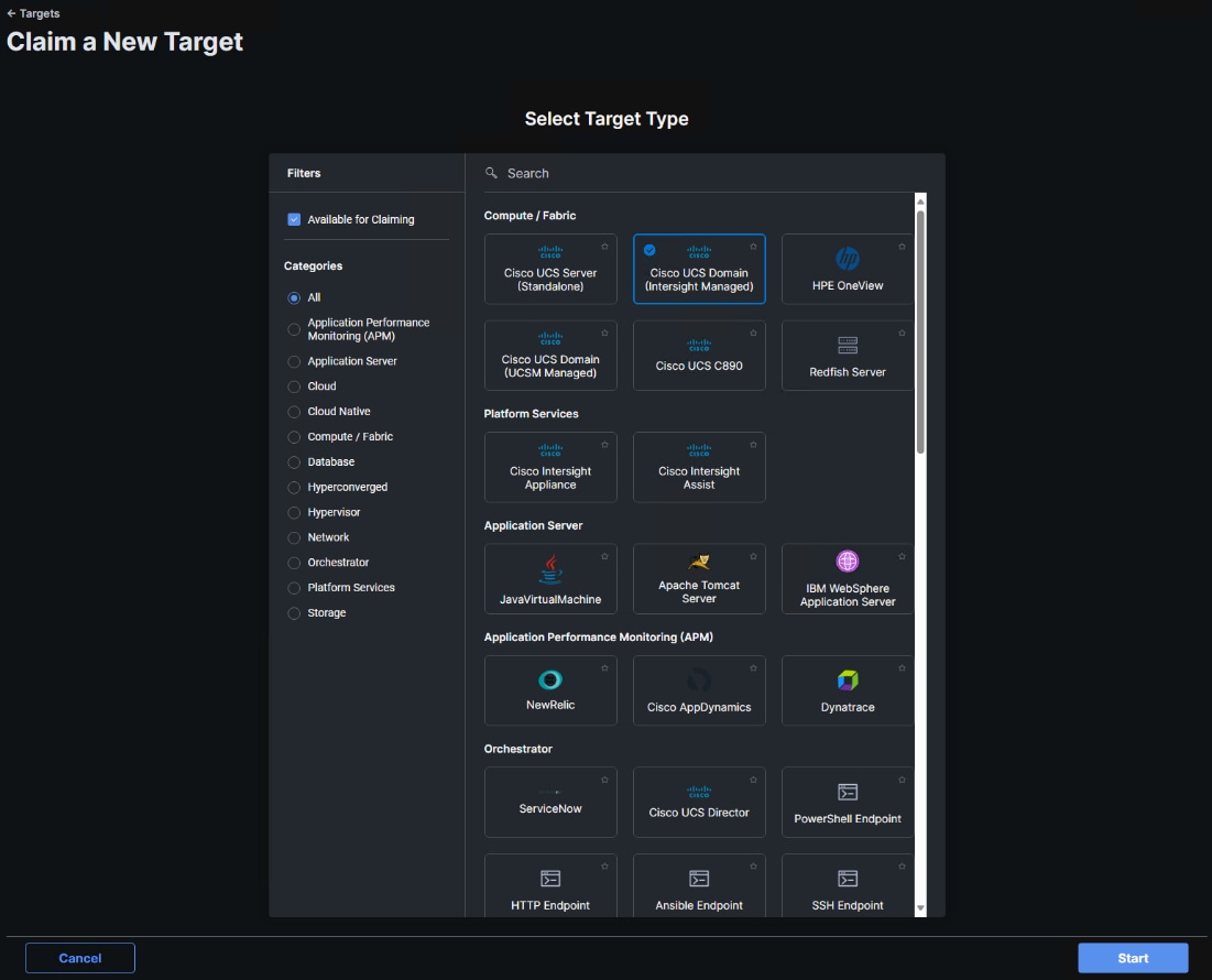
Step 5. Click Claim a New Target.
Step 6. Select Cisco UCS Domain (Intersight Managed) and click Start.
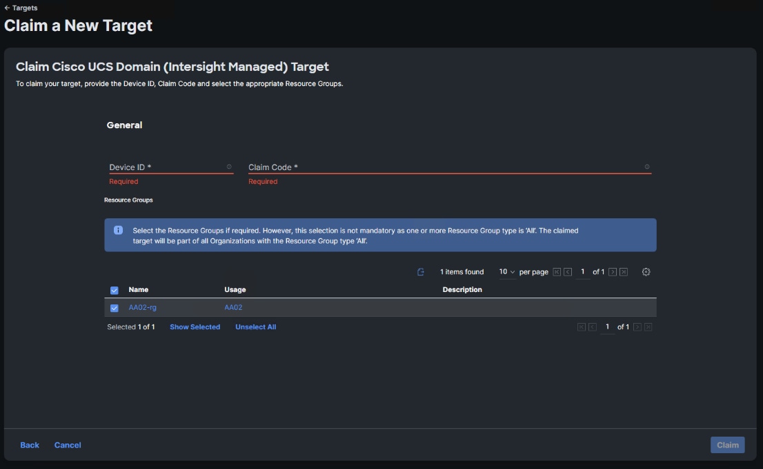
Step 7. Copy and paste the Device ID and Claim from the Cisco UCS FI to Intersight.
Step 8. Select the previously created Resource Group and click Claim.
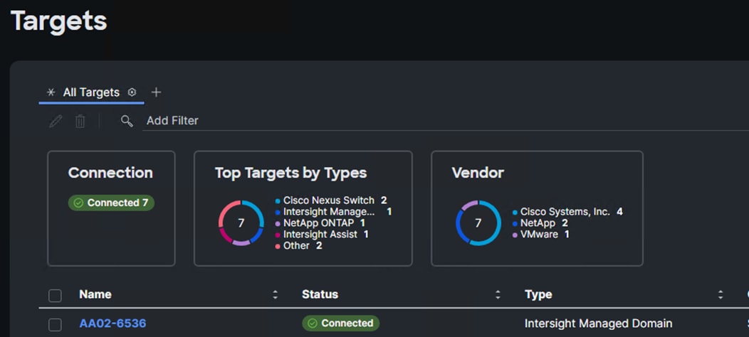
With a successful device claim, Cisco UCS FI should appear as a target in Cisco Intersight as shown below:
Procedure 7. Verify Addition of Cisco UCS Fabric Interconnects to Cisco Intersight
Step 1. Log into the web GUI of the Cisco UCS Fabric Interconnect and click the browser refresh button.
The fabric interconnect status should now be set to Claimed.
Procedure 8. Upgrade Fabric Interconnect Firmware using Cisco Intersight
If your Cisco UCS Fabric Interconnects are not already running the suggested firmware release, upgrade them to the suggested release or later.
Step 1. Log into the Cisco Intersight portal.
Step 2. From the drop-down list, select Infrastructure Service and then select Fabric Interconnects.
Step 3. Click the ellipses “…” at the end of the row for either of the Fabric Interconnects and select Upgrade Firmware.
Step 4. Click Start.
Step 5. Verify the Fabric Interconnect information and click Next.
Step 6. Enable Advanced Mode using the toggle switch and uncheck Fabric Interconnect Traffic Evacuation.
Step 7. Select the suggested release or later from the list and click Next.
Step 8. Verify the information and click Upgrade to start the upgrade process.
Step 9. Watch the Request panel of the main Intersight screen since the system will ask for user permission before upgrading each FI. Click the Circle with Arrow and follow the prompts on screen to grant permission.
Step 10. Wait for both the FIs to successfully upgrade.
Procedure 9. Ansible Cisco UCS IMM Configuration
To configure the Cisco UCS from the Ansible management workstation, follow the steps in this procedure.
Step 1. To execute the playbooks against your Intersight account, you need to create an API key and save a SecretKey.txt file from your Cisco Intersight account:
a. In Cisco Intersight, select System > Settings > API > API Keys.
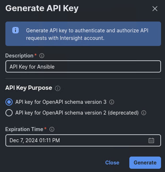
b. Click Generate API Key.
c. Under Generate API Key, enter a Description (for example, API Key for Ansible) and select API key for OpenAPI schema version 3. The default account setting for API Key Expiration time is 180 days (around 6 months). This can be changed, including turning off API Key Expiration in the account settings. Select an acceptable API Key Expiration Time and click Generate.
d. In the Generate API Key window, click the upper ![]() icon to copy the API Key ID to the clipboard. Paste this key into the api_key_id variable in the FlexPod-Base-IMM/group_vars/ucs.yml variable file and save it.
icon to copy the API Key ID to the clipboard. Paste this key into the api_key_id variable in the FlexPod-Base-IMM/group_vars/ucs.yml variable file and save it.
e. Using an editor, open the FlexPod-Base-IMM/FlexPod-Base-IMM/SecretKey.txt file and clear all text from the file. Then click the lower ![]() icon in the Generate API Key window and paste the Secret Key into the SecretKey.txt file and save it.
icon in the Generate API Key window and paste the Secret Key into the SecretKey.txt file and save it.
f. Select the checkbox next to I have downloaded the Secret Key and click Close.
Step 2. Edit the following variable files to ensure proper UCS variables are entered:
● FlexPod-Base-IMM/group_vars/secrets.yml
● FlexPod-Base-IMM/group_vars/all.yml
● FlexPod-Base-IMM/group_vars/ucs.yml
Step 3. To set up the Cisco Intersight IMM UCS Domain and Chassis Policies and Profiles, run the following:
ansible-playbook ./Setup_UCS_Domain_Chassis_Profiles.yml
Procedure 10. Attach UCS Domain Profile to UCS Domain
Step 1. Log into the Cisco Intersight portal.
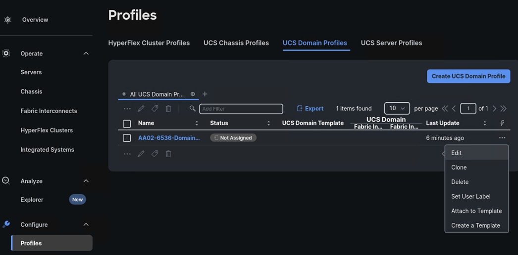
Step 2. From the drop-down list, select Configure > Profiles.
Step 3. In the main window under Profiles, select UCS Domain Profiles.
Step 4. To the right of the recently created Domain Profile, click … and select Edit.
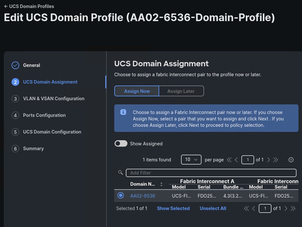
Step 5. Verify the General profile information and click Next.
Step 6. Select the UCS Domain and click Next.
Step 7. Verify the VLAN and VSAN Policies and click Next.
Step 8. Verify the Ports Configuration Policies and click Next.
Step 9. Verify the UCS Domain Configuration Policies and click Next.
Step 10. Verify the Summary information and click Deploy.
Step 11. Wait until the profile is deployed and all chassis and servers are discovered.
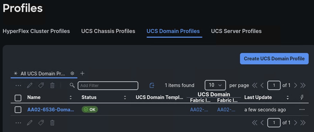
Procedure 11. Verify Cisco UCS Domain Profile Deployment
When the Cisco UCS domain profile has been successfully deployed, the Cisco UCS chassis and the blades should be successfully discovered.
Note: It takes a while to discover the blades and rackmounts for the first time. Watch the number of outstanding requests in Cisco Intersight.
Step 1. Log into Cisco Intersight. Under Configure > Profiles > UCS Domain Profiles, verify that the domain profile has been successfully deployed.
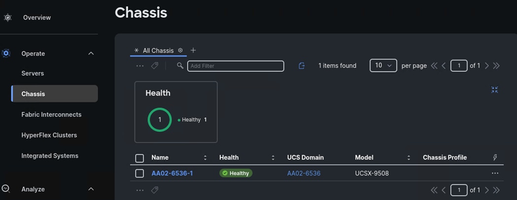
Step 2. Verify that the chassis (either UCSX-9508 or UCS 5108 chassis) has been discovered and is visible under Operate > Chassis.
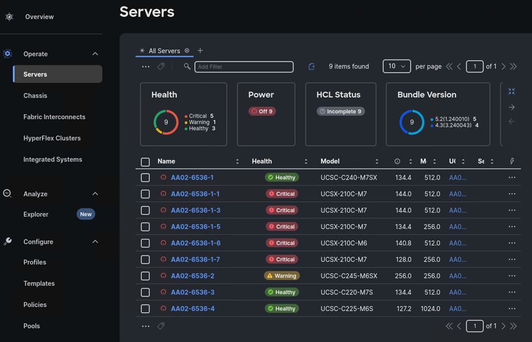
Step 3. Verify that the servers have been successfully discovered and are visible under Operate > Servers.
Procedure 12. Create Chassis Profile Template (optional)
If you have more than one chassis in your environment, you can create a Chassis Profile Template and from it derived additional and identical Chassis Profiles to attach to other chassis.
Note: A Cisco UCS chassis profile configures either a UCS X9508 or UCS 5108 chassis through reusable policies. It defines the characteristics of power distribution and fan configuration in the chassis. One Cisco UCS chassis profile can be assigned to one chassis.
Step 1. Log into the Cisco Intersight portal.
Step 2. From the drop-down list, select Configure > Profiles.
Step 3. In the main window under Profiles, select UCS Chassis Profiles.
Step 4. From Chassis Profile created with Ansible, click … and select Create a Template.
Step 5. In the Create a Template window, enter a Name (for example, Default-Chassis-Template) and edit the description. Click Next.
Step 6. Verify the Summary information and click Close.
Step 7. Select Templates on the left and the UCS Chassis Profile Templates tab to verify creation of the template.
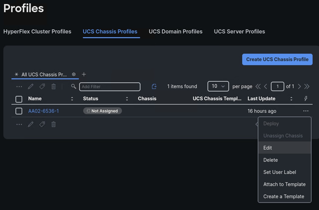
Procedure 13. Attach UCS Chassis Profile to Chassis
Step 1. Log into the Cisco Intersight portal.
Step 2. From the drop-down list, select Configure > Profiles.
Step 3. In the main window under Profiles, select UCS Chassis Profiles.
Step 4. From the Chassis Profile created with Ansible, click … and select Edit.
Step 5. Verify the General information for the profile and click Next.
Step 6. Select the first chassis in the list and click Next.
Step 7. Verify the Chassis Configuration policies and click Next.
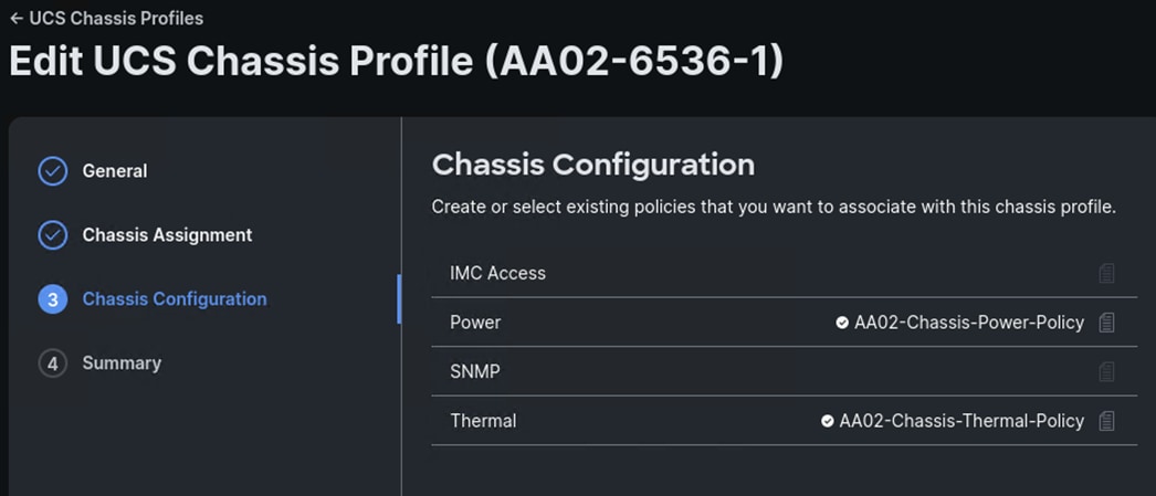
Step 8. Verify the Summary information and click Deploy. Click Deploy again. The profile will be deployed to the chassis.
Step 9. If you have additional chassis, profiles for the additional chassis can be derived from the template created above and attached to the additional chassis.
This chapter contains the following:
This chapter explains how to configure the Cisco MDS 9000s for use in a FlexPod environment. The configuration explained in this section is only needed when configuring Fibre Channel and FC-NVMe storage access.
Note: If FC connectivity is not required in the FlexPod deployment, this section can be skipped.
Note: If the Cisco Nexus 93180YC-FX or 93360YC-FX2 switches are being used for SAN switching in this FlexPod Deployment, refer to section FlexPod with Cisco Nexus SAN Switching Configuration – Part 2 in the Appendix of this document.
Follow the physical connectivity guidelines for FlexPod as explained in Physical Topology section.
The following procedures describe how to configure the Cisco MDS switches for use in a base FlexPod environment. This procedure assumes you are using the Cisco MDS 9132T with NX-OS 9.4(2a).
Procedure 1. Set up Cisco MDS 9132T A and 9132T B
Note: On initial boot and connection to the serial or console port of the switch, the NX-OS setup should automatically start and attempt to enter Power on Auto Provisioning. Enter y to get to the System Admin Account Setup.
Step 1. Configure the switch using the command line:
---- System Admin Account Setup ----
Do you want to enforce secure password standard (yes/no) [y]: Enter
Enter the password for "admin": <password>
Confirm the password for "admin": <password>
Would you like to enter the basic configuration dialog (yes/no): yes
Create another login account (yes/no) [n]: Enter
Configure read-only SNMP community string (yes/no) [n]: Enter
Configure read-write SNMP community string (yes/no) [n]: Enter
Enter the switch name : <mds-A-hostname>
Continue with Out-of-band (mgmt0) management configuration? (yes/no) [y]: Enter
Mgmt0 IPv4 address : <mds-A-mgmt0-ip>
Mgmt0 IPv4 netmask : <mds-A-mgmt0-netmask>
Configure the default gateway? (yes/no) [y]: Enter
IPv4 address of the default gateway : <mds-A-mgmt0-gw>
Configure advanced IP options? (yes/no) [n]: Enter
Enable the ssh service? (yes/no) [y]: Enter
Type of ssh key you would like to generate (dsa/rsa) [rsa]: Enter
Number of rsa key bits <1024-2048> [1024]: 2048
Enable the telnet service? (yes/no) [n]: Enter
Configure congestion/no_credit drop for fc interfaces? (yes/no) [y]: Enter
Enter the type of drop to configure congestion/no_credit drop? (con/no) [c]: Enter
Enter milliseconds in multiples of 10 for congestion-drop for logical-type edge
in range (<200-500>/default), where default is 500. [d]: Enter
Enable the http-server? (yes/no) [y]: Enter
Configure clock? (yes/no) [n]: Enter
Configure timezone? (yes/no) [n]: Enter
Configure summertime? (yes/no) [n]: Enter
Configure the ntp server? (yes/no) [n]: Enter
Configure default switchport interface state (shut/noshut) [shut]: Enter
Configure default switchport trunk mode (on/off/auto) [on]: auto
Configure default switchport port mode F (yes/no) [n]: y
Configure default zone policy (permit/deny) [deny]: Enter
Enable full zoneset distribution? (yes/no) [n]: y
Configure default zone mode (basic/enhanced) [basic]: Enter
Note: RHEL 9.5 requires a 2048-bit RSA key.
Step 2. Review the configuration.
Would you like to edit the configuration? (yes/no) [n]: Enter
Use this configuration and save it? (yes/no) [y]: Enter
Procedure 2. FlexPod Cisco MDS Switch Ansible Configuration
Step 1. Add MDS switch ssh keys to /home/admin/.ssh/known_hosts. Adjust known_hosts as necessary if errors occur:
ssh admin@<mds-A-mgmt0-ip>
exit
ssh admin@<mds-B-mgmt0-ip>
exit
Step 2. Edit the following variable files to ensure proper MDS variables are entered:
● FlexPod-Base-IMM/group_vars/secrets.yml
● FlexPod-Base-IMM/inventory
● FlexPod-Base-IMM/group_vars/all.yml
● FlexPod-Base-IMM/host_vars/mdsA.yml
● FlexPod-Base-IMM/host_vars/mdsB.yml
● FlexPod-Base-IMM/roles/MDSconfig/defaults/main.yml
Step 3. From FlexPod-Base-IMM/FlexPod-Base-IMM, run the Setup_MDS.yml Ansible playbook:
ansible-playbook ./Setup_MDS.yml -i inventory
Step 4. If the playbook fails to complete, in order to avoid timing issues with port setup, ssh into each switch and set “no shutdown” on each interface in the port-channel to the Cisco UCS fabric interconnects and re-run the playbook:
config t
int fc1/5-8
no shutdown
exit
exit
exit
Step 5. Smart licensing should be setup in the MDS switches. For more information, see: Cisco MDS 9000 Series Licensing Guide, Release 9.x.
Claim Targets to Cisco Intersight
This chapter contains the following:
● Claim NetApp ONTAP Storage Targets
● Claim Cisco Nexus Switch Targets
● Claim Cisco MDS Switch Targets
If you have a management pod capable of running virtual machines, you can install Cisco Intersight Assist and NetApp Active IQ Unified Manager (AIQUM) and integrate a number of the FlexPod components to Cisco Intersight as targets. You will first need to install, claim, and configure the Intersight Assist appliance using the installation instructions in Cisco Intersight Virtual Appliance and Intersight Assist Getting Started Guide. Once the Assist is claimed to Intersight, you can then begin claiming targets through the Assist.
Procedure 1. Claim NetApp ONTAP Storage Targets
NetApp ONTAP Storage Targets can be claimed through Intersight Assist and NetApp AIQUM. NetApp AIQUM can be installed on VMware from OVA, on Microsoft Windows, or on Red Hat Enterprise Linux 8. Install AIQUM with instructions from https://mysupport.netapp.com and configure AIQUM, making sure to enable the API Gateway feature in AIQUM and adding any NetApp ONTAP clusters in the FlexPod to AIQUM.
Step 1. Log into the Cisco Intersight portal.
Step 2. From the drop-down list, select System > Targets. Select Claim a New Target.
Step 3. Under Select Target Type, scroll down and select NetApp Active IQ Unified Manager and click Start.
Step 4. Make sure the correct Cisco Assist is selected and enter the AIQUM Hostname/IP Address or FQDN and then the username and password used to configure AIQUM. Click Claim.

Step 5. Once the target is successfully claimed, from the drop-down list select Infrastructure Service. Select Storage. The NetApp storage cluster(s) configured in NetApp AIQUM appear in the list.
Procedure 2. Claim Cisco Nexus Switch Targets
A Cisco Nexus switch can be claimed two ways in Cisco Intersight. The first type of claim is using the switch’s native device connector and is used for the Intersight Connected TAC feature. The second type of claim utilizes Cisco Assist, provides inventory, and alerts information, and allows Intersight Cloud Orchestrator (ICO) workflows to be run on the switch.
Step 1. Log into the Cisco Intersight portal.
Step 2. From the drop-down list, select System > Targets. Select Claim a New Target.
Step 3. Under Select Target Type, select Cisco Nexus Switch and click Start.
Step 4. To claim the switch for the Intersight Connected TAC feature, leave Claim Target selected and open a ssh connection to the switch. Once connected to the switch, type the following commands:
show system device-connector claim-info
Step 5. Use the switch SerialNumber to fill in the Intersight Device ID field and the switch SecurityToken to fill in the Intersight Claim Code field. Select the appropriate Resource Group(s) and click Claim.
Step 6. To claim the switch for inventory and alerts information and for ICO workflows, select Claim a New Target.
Step 7. Under Select Target Type, select Cisco Nexus Switch and click Start.
Step 8. Select Claim Target with Cisco Assist. Make sure the correct Cisco Assist is selected and enter the switch’s Hostname/IP Address or FQDN and then an administrator user id and password for the switch. Click Claim.
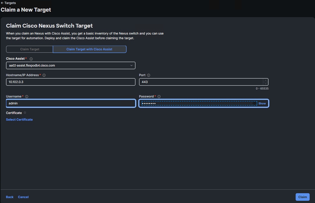
Step 9. It is not an issue to claim a switch both ways. Repeat steps 1 - 8 to claim all Nexus switches into Cisco Intersight.
Procedure 3. Claim Cisco MDS Switch Targets
A Cisco MDS switch can also be claimed two ways in Cisco Intersight. The first type of claim is using the switch’s native device connector and is used for the Intersight Connected TAC feature. The second type of claim utilizes Cisco Assist, provides inventory, and alerts information, and allows Intersight Cloud Orchestrator (ICO) workflows to be run on the switch. The second type of claim is currently in Tech Preview.
Step 1. Log into the Cisco Intersight portal.
Step 2. From the drop-down list, select System > Targets. Select Claim a New Target.
Step 3. Under Select Target Type, select Cisco MDS Switch and click Start.
Step 4. To claim the switch for the Intersight Connected TAC feature, leave Claim Target selected and open a ssh connection to the switch. Once connected to the switch, type the following commands:
show intersight claim-info
Step 5. Use the switch SerialNumber to fill in the Intersight Device ID field and the switch SecurityToken to fill in the Intersight Claim Code field. Select the appropriate Resource Group(s) and click Claim.
Step 6. To claim the switch for inventory and alerts information and for ICO workflows, select Claim a New Target.
Step 7. Under Select Target Type, select Cisco MDS Switch and click Start.
Step 8. Select Claim Target with Cisco Assist. Make sure the correct Cisco Assist is selected and enter the switch’s Hostname/IP Address or FQDN, Port 8443, and then an administrator user id and password for the switch. Click Claim.
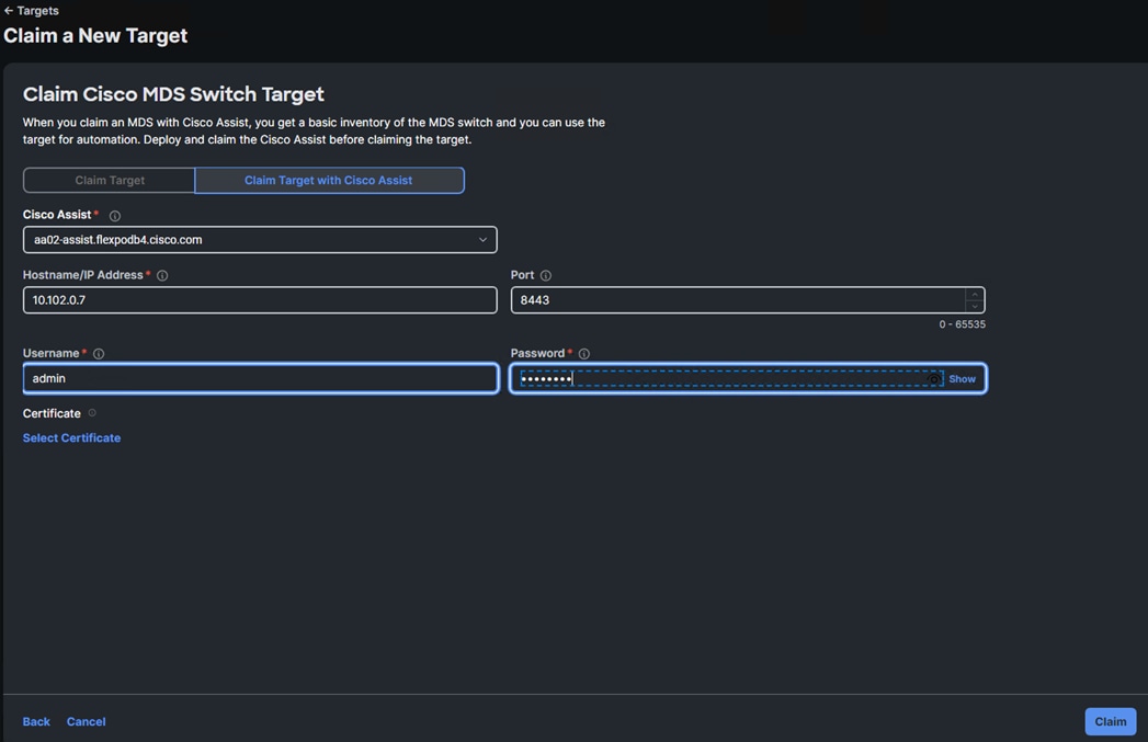
Step 9. It is not an issue to claim a switch both ways. Repeat steps 1 - 8 to claim all MDS switches into Cisco Intersight.
John George, Technical Marketing Engineer, Cisco Systems, Inc.
John has been involved in designing, developing, validating, and supporting the FlexPod Converged Infrastructure since it was developed over 13 years ago. Before his role with FlexPod, he supported and administered a large worldwide training network and VPN infrastructure. John holds a master’s degree in Computer Engineering from Clemson University.
Kamini Singh, Technical Marketing Engineer, Hybrid Cloud Infra & OEM Solutions, NetApp
Kamini Singh is a Technical Marketing engineer at NetApp. She has around five years of experience in data center infrastructure solutions. She focuses on FlexPod hybrid cloud infrastructure solution design, implementation, validation, automation, and sales enablement. Kamini holds a bachelor’s degree in Electronics and Communication and a master’s degree in Communication Systems.
Acknowledgements
For their support and contribution to the design, validation, and creation of this Cisco Validated Design, the authors would like to thank:
● Haseeb Niazi, Principal Technical Marketing Engineer, Cisco Systems, Inc.
● Paniraja Koppa, Technical Marketing Engineer, Cisco Systems, Inc.
Appendix
This appendix contains the following:
● FlexPod with Cisco Nexus SAN Switching Configuration – Part 1
● FlexPod with Cisco Nexus 93360YC-FX2 SAN Switching Configuration – Part 2
Note: The features and functionality explained in this Appendix are optional configurations which can be helpful in configuring and managing the FlexPod deployment.
FlexPod with Cisco Nexus SAN Switching Configuration – Part 1
If the Cisco Nexus switches are to be used for both LAN and SAN switching in the FlexPod configuration, either an automated configuration with Ansible or a manual configuration can be done. For either configuration method, the following base switch setup must be done manually. Figure 6 shows the validation lab cabling for this setup.
FlexPod Cisco Nexus 93360YC-FX2 SAN Switching Base Configuration
The following procedures describe how to configure the Cisco Nexus 93360YC-FX2 switches for use in a base FlexPod environment that uses the switches for both LAN and SAN switching. This procedure assumes you’re using Cisco Nexus 9000 10.4(4)M. This procedure also assumes that you have created an FCoE Uplink Port Channel on the appropriate ports in the Cisco UCS IMM Port Policies for each UCS fabric interconnect.
Procedure 1. Set Up Initial Configuration in Cisco Nexus 93360YC-FX2 A
Step 1. Configure the switch:
Note: On initial boot and connection to the serial or console port of the switch, the NX-OS setup should automatically start and attempt to enter Power on Auto Provisioning.
Abort Power On Auto Provisioning [yes - continue with normal setup, skip - bypass password and basic configuration, no - continue with Power On Auto Provisioning] (yes/skip/no)[no]: yes
Disabling POAP.......Disabling POAP
poap: Rolling back, please wait... (This may take 5-15 minutes)
---- System Admin Account Setup ----
Do you want to enforce secure password standard (yes/no) [y]: Enter
Enter the password for "admin": <password>
Confirm the password for "admin": <password>
Would you like to enter the basic configuration dialog (yes/no): yes
Create another login account (yes/no) [n]: Enter
Configure read-only SNMP community string (yes/no) [n]: Enter
Configure read-write SNMP community string (yes/no) [n]: Enter
Enter the switch name: <nexus-A-hostname>
Continue with Out-of-band (mgmt0) management configuration? (yes/no) [y]: Enter
Mgmt0 IPv4 address: <nexus-A-mgmt0-ip>
Mgmt0 IPv4 netmask: <nexus-A-mgmt0-netmask>
Configure the default gateway? (yes/no) [y]: Enter
IPv4 address of the default gateway: <nexus-A-mgmt0-gw>
Configure advanced IP options? (yes/no) [n]: Enter
Enable the telnet service? (yes/no) [n]: Enter
Enable the ssh service? (yes/no) [y]: Enter
Type of ssh key you would like to generate (dsa/rsa) [rsa]: Enter
Number of rsa key bits <1024-2048> [1024]: 2048
Configure the ntp server? (yes/no) [n]: Enter
Configure default interface layer (L3/L2) [L2]: Enter
Configure default switchport interface state (shut/noshut) [noshut]: shut
Enter basic FC configurations (yes/no) [n]: y
Configure default physical FC switchport interface state (shut/noshut) [shut]: Enter
Configure default switchport trunk mode (on/off/auto) [on]: auto
Configure default zone policy (permit/deny) [deny]: Enter
Enable full zoneset distribution? (yes/no) [n]: y
Configure CoPP system profile (strict/moderate/lenient/dense) [strict]: Enter
Would you like to edit the configuration? (yes/no) [n]: Enter
Step 2. Review the configuration summary before enabling the configuration:
Use this configuration and save it? (yes/no) [y]: Enter
Procedure 2. Set Up Initial Configuration in Cisco Nexus 93360YC-FX2 B
Step 1. Configure the switch:
Note: On initial boot and connection to the serial or console port of the switch, the NX-OS setup should automatically start and attempt to enter Power on Auto Provisioning.
Abort Power On Auto Provisioning [yes - continue with normal setup, skip - bypass password and basic configuration, no - continue with Power On Auto Provisioning] (yes/skip/no)[no]: yes
Disabling POAP.......Disabling POAP
poap: Rolling back, please wait... (This may take 5-15 minutes)
---- System Admin Account Setup ----
Do you want to enforce secure password standard (yes/no) [y]: Enter
Enter the password for "admin": <password>
Confirm the password for "admin": <password>
Would you like to enter the basic configuration dialog (yes/no): yes
Create another login account (yes/no) [n]: Enter
Configure read-only SNMP community string (yes/no) [n]: Enter
Configure read-write SNMP community string (yes/no) [n]: Enter
Enter the switch name: <nexus-B-hostname>
Continue with Out-of-band (mgmt0) management configuration? (yes/no) [y]: Enter
Mgmt0 IPv4 address: <nexus-B-mgmt0-ip>
Mgmt0 IPv4 netmask: <nexus-B-mgmt0-netmask>
Configure the default gateway? (yes/no) [y]: Enter
IPv4 address of the default gateway: <nexus-B-mgmt0-gw>
Configure advanced IP options? (yes/no) [n]: Enter
Enable the telnet service? (yes/no) [n]: Enter
Enable the ssh service? (yes/no) [y]: Enter
Type of ssh key you would like to generate (dsa/rsa) [rsa]: Enter
Number of rsa key bits <1024-2048> [1024]: 2048
Configure the ntp server? (yes/no) [n]: Enter
Configure default interface layer (L3/L2) [L2]: Enter
Configure default switchport interface state (shut/noshut) [noshut]: shut
Enter basic FC configurations (yes/no) [n]: y
Configure default physical FC switchport interface state (shut/noshut) [shut]: Enter
Configure default switchport trunk mode (on/off/auto) [on]: auto
Configure default zone policy (permit/deny) [deny]: Enter
Enable full zoneset distribution? (yes/no) [n]: y
Configure CoPP system profile (strict/moderate/lenient/dense) [strict]: Enter
Would you like to edit the configuration? (yes/no) [n]: Enter
Step 2. Review the configuration summary before enabling the configuration:
Use this configuration and save it? (yes/no) [y]: Enter
Note: SAN switching requires both the SAN_ENTERPRISE_PKG and FC_PORT_ACTIVATION_PKG licenses. Ensure these licenses are installed on each Nexus switch.
Note: This section is structured as a green field switch setup. If existing switches that are switching active traffic are being setup, execute this procedure down through Perform TCAM Carving and Configure Unified Ports in Cisco Nexus 93180YC-FX A and B first on one switch and then when that is completed, execute on the other switch.
Procedure 3. Install feature-set fcoe in Cisco Nexus 93360YC-FX2 A and B
Step 1. Run the following commands to set global configurations:
config t
install feature-set fcoe
feature-set fcoe
system default switchport trunk mode auto
system default switchport mode F
Note: These steps are provided in case the basic FC configurations were not configured in the switch setup script de-tailed in the previous section.
Procedure 4. Set System-Wide QoS Configurations in Cisco Nexus 93360YC-FX2 A and B
Step 1. Run the following commands to set global configurations:
config t
system qos
service-policy type queuing input default-fcoe-in-que-policy
service-policy type queuing output default-fcoe-8q-out-policy
service-policy type network-qos default-fcoe-8q-nq-policy
copy run start
Procedure 5. Perform TCAM Carving and Configure Unified Ports (UP) in Cisco Nexus 93360YC-FX2 A and B
Note: SAN switching requires TCAM carving for lossless fibre channel no-drop support. Also, unified ports need to be converted to fc ports.
Note: On the Cisco Nexus 93360YC-FX2, UP ports are converted to FC in groups of 4 in columns, for example, 1,2,49,50.
Step 1. Run the following commands:
hardware access-list tcam region ing-racl 1536
hardware access-list tcam region ing-ifacl 256
hardware access-list tcam region ing-redirect 256
slot 1
port 1-4,49-52 type fc
copy running-config startup-config
reload
This command will reboot the system. (y/n)? [n] y
Note: RHEL 9.5 requires a 2048-bit RSA key.
Step 2. After the switch reboots, log back in as admin. Run the following commands:
show hardware access-list tcam region |i i ing-racl
show hardware access-list tcam region |i i ing-ifacl
show hardware access-list tcam region |i i ing-redirect
show int status
FlexPod Cisco Nexus 93360YC-FX2 SAN Switching Ethernet Switching Automated Configuration
For the automated configuration of the Ethernet part of the Cisco Nexus 93360YC-FX2 switches when using the switches for SAN switching, once the base configuration is set, return to Ansible Nexus Switch Configuration, and execute from there.
FlexPod with Cisco Nexus 93360YC-FX2 SAN Switching Configuration – Part 2
Note: If the Cisco Nexus 93360YC-FX2 switch is being used for SAN Switching, this section should be completed in place of the Cisco MDS section of this document.
Procedure 1. FlexPod Cisco Nexus 93360YC-FX2 SAN Switching Automated Configuration
Automate the configuration of the SAN part of the Cisco Nexus 93360YC-FX2 switches when using the switches for SAN switching.
Step 1. Verify Nexus switch ssh keys are in /home/admin/.ssh/known_hosts. Adjust known_hosts as necessary if errors occur.
ssh admin@<nexus-A-mgmt0-ip>
exit
ssh admin@<nexus-B-mgmt0-ip>
exit
Step 2. Edit the following variable files to ensure proper Cisco Nexus SAN variables are entered:
● FlexPod-Base-IMM/group_vars/secrets.yml
● FlexPod-Base-IMM/inventory
● FlexPod-Base-IMM/group_vars/all.yml
● FlexPod-Base-IMM/group_vars/nss.yml
● FlexPod-Base-IMM/host_vars/n9kSSA.yml
● FlexPod-Base-IMM/host_vars/n9kSSB.yml
● FlexPod-Base-IMM/roles/NEXUSSANconfig/defaults/main.yml
Step 3. From FlexPod-Base-IMM/FlexPod-Base-IMM, run the Setup_NexusSAN.yml Ansible playbook.
ansible-playbook ./Setup_NexusSAN.yml -i inventory
Procedure 2. Switch Testing Commands
Step 1. The following commands can be used to check for correct switch configuration:
Note: Some of these commands need to run after further configuration of the FlexPod components are complete to see complete results.
show run
show run int
show int
show int status
show int brief
show flogi database
show device-alias database
show zone
show zoneset
show zoneset active
Procedure 1. Cisco Nexus and MDS Backups
The configuration of the Cisco Nexus 9000 and Cisco MDS 9132T switches can be backed up manually at any time with the copy command, but automated backups can be enabled using the NX-OS feature scheduler.
An example of setting up automated configuration backups of one of the NX-OS switches is shown below:
config t
feature scheduler
scheduler logfile size 1024
scheduler job name backup-cfg
copy running-config tftp://<server-ip>/$(SWITCHNAME)-cfg.$(TIMESTAMP) vrf management
exit
scheduler schedule name daily
job name backup-cfg
time daily 2:00
end
Note: Using “vrf management” in the copy command is only needed when Mgmt0 interface is part of VRF management. “vrf management is not needed in Cisco MDS switches.
Step 1. Verify the scheduler job has been correctly setup using following command(s):
show scheduler job
Job Name: backup-cfg
--------------------
copy running-config tftp://10.1.156.150/$(SWITCHNAME)-cfg.$(TIMESTAMP) vrf management
==============================================================================
show scheduler schedule
Schedule Name : daily
---------------------------
User Name : admin
Schedule Type : Run every day at 2 Hrs 0 Mins
Last Execution Time : Yet to be executed
-----------------------------------------------
Job Name Last Execution Status
-----------------------------------------------
backup-cfg -NA-
==============================================================================
The documentation for the feature scheduler can be found here: https://www.cisco.com/c/en/us/td/docs/dcn/nx-os/nexus9000/102x/configuration/system-management/cisco-nexus-9000-series-nx-os-system-management-configuration-guide-102x/m-configuring-the-scheduler-10x.html
Procedure 2. NetApp ONTAP Configuration Backup
The configuration backup files of the NetApp ONTAP cluster and nodes are automatically created according to the following schedules:
● Every 8 hours
● Daily
● Weekly
At each of these times, a node configuration backup file is created on each healthy node in the cluster. All of these node configuration backup files are then collected in a single cluster configuration backup file along with the replicated cluster configuration and saved on one or more nodes in the cluster.
An example of viewing the ONTAP cluster configuration backup files is shown below:
AA16-A400::> set advanced
Warning: These advanced commands are potentially dangerous; use them only when directed to do so by NetApp personnel.
Do you want to continue? {y|n}: y
AA16-A400::*> row 0
(rows)
AA16-A400::*> system configuration backup show
Node Backup Name Time Size
--------- ----------------------------------------- ------------------ -----
AA16-A400-01 AA16-A400.8hour.2023-08-31.18_15_00.7z 08/31 18:15:00 34.60MB
AA16-A400-01 AA16-A400.8hour.2023-09-01.02_15_00.7z 09/01 02:15:00 35.65MB
AA16-A400-01 AA16-A400.8hour.2023-09-01.10_15_00.7z 09/01 10:15:00 36.05MB
AA16-A400-01 AA16-A400.daily.2023-08-31.00_10_01.7z 08/31 00:10:01 34.87MB
AA16-A400-01 AA16-A400.daily.2023-09-01.00_10_01.7z 09/01 00:10:01 35.09MB
AA16-A400-01 AA16-A400.weekly.2023-08-27.00_15_00.7z 08/27 00:15:00 23.50MB
AA16-A400-02 AA16-A400.8hour.2023-09-01.02_15_00.7z 09/01 02:15:00 35.65MB
AA16-A400-02 AA16-A400.8hour.2023-09-01.10_15_00.7z 09/01 10:15:00 36.05MB
AA16-A400-02 AA16-A400.daily.2023-08-30.00_10_00.7z 08/30 00:10:00 32.69MB
AA16-A400-02 AA16-A400.daily.2023-08-31.00_10_01.7z 08/31 00:10:01 34.87MB
AA16-A400-02 AA16-A400.daily.2023-09-01.00_10_01.7z 09/01 00:10:01 35.09MB
AA16-A400-02 AA16-A400.weekly.2023-08-27.00_15_00.7z 08/27 00:15:00 23.50MB
12 entries were displayed.
AA16-A400::*> set admin
AA16-A400::>
You can use the system configuration backup settings commands to manage configuration backup schedules and specify a remote URL (HTTP, HTTPS, FTP, FTPS, or TFTP ) where the configuration backup files will be uploaded in addition to the default locations in the cluster.
An example of setting up an automated ONTAP cluster configuration backup upload destination using TFTP is shown below:
AA16-A400::> set advanced
Warning: These advanced commands are potentially dangerous; use them only when directed to do so by NetApp personnel.
Do you want to continue? {y|n}: y
AA16-A400::*> system configuration backup setting modify -destination tftp://10.1.156.150/ONTAP
AA16-A400::*> system configuration backup setting show
Backup Destination URL Username
-------------------------------------------------- -------------
tftp://10.1.156.150/ONTAP
AA16-A400::*> set admin
AA16-A400::>
For comments and suggestions about this guide and related guides, join the discussion on Cisco Community at https://cs.co/en-cvds.
CVD Program
ALL DESIGNS, SPECIFICATIONS, STATEMENTS, INFORMATION, AND RECOMMENDATIONS (COLLECTIVELY, "DESIGNS") IN THIS MANUAL ARE PRESENTED "AS IS," WITH ALL FAULTS. CISCO AND ITS SUPPLIERS DISCLAIM ALL WARRANTIES, INCLUDING, WITHOUT LIMITATION, THE WARRANTY OF MERCHANTABILITY, FITNESS FOR A PARTICULAR PURPOSE AND NONINFRINGEMENT OR ARISING FROM A COURSE OF DEALING, USAGE, OR TRADE PRACTICE. IN NO EVENT SHALL CISCO OR ITS SUPPLIERS BE LIABLE FOR ANY INDIRECT, SPECIAL, CONSEQUENTIAL, OR INCIDENTAL DAMAGES, INCLUDING, WITHOUT LIMITATION, LOST PROFITS OR LOSS OR DAMAGE TO DATA ARISING OUT OF THE USE OR INABILITY TO USE THE DESIGNS, EVEN IF CISCO OR ITS SUPPLIERS HAVE BEEN ADVISED OF THE POSSIBILITY OF SUCH DAMAGES.
THE DESIGNS ARE SUBJECT TO CHANGE WITHOUT NOTICE. USERS ARE SOLELY RESPONSIBLE FOR THEIR APPLICATION OF THE DESIGNS. THE DESIGNS DO NOT CONSTITUTE THE TECHNICAL OR OTHER PROFESSIONAL ADVICE OF CISCO, ITS SUPPLIERS OR PARTNERS. USERS SHOULD CONSULT THEIR OWN TECHNICAL ADVISORS BEFORE IMPLE-MENTING THE DESIGNS. RESULTS MAY VARY DEPENDING ON FACTORS NOT TESTED BY CISCO.
CCDE, CCENT, Cisco Eos, Cisco Lumin, Cisco Nexus, Cisco StadiumVision, Cisco TelePresence, Cisco WebEx, the Cisco logo, DCE, and Welcome to the Human Network are trademarks; Changing the Way We Work, Live, Play, and Learn and Cisco Store are service marks; and Access Registrar, Aironet, AsyncOS, Bringing the Meeting To You, Catalyst, CCDA, CCDP, CCIE, CCIP, CCNA, CCNP, CCSP, CCVP, Cisco, the Cisco Certified Internetwork Expert logo, Cisco IOS, Cisco Press, Cisco Systems, Cisco Systems Capital, the Cisco Systems logo, Cisco Unified Computing System (Cisco UCS), Cisco UCS B-Series Blade Servers, Cisco UCS C-Series Rack Servers, Cisco UCS S-Series Storage Servers, Cisco UCS X-Series, Cisco UCS Manager, Cisco UCS Management Software, Cisco Unified Fabric, Cisco Application Centric Infrastructure, Cisco Nexus 9000 Series, Cisco Nexus 7000 Series. Cisco Prime Data Center Network Manager, Cisco NX-OS Software, Cisco MDS Series, Cisco Unity, Collaboration Without Limitation, EtherFast, EtherSwitch, Event Center, Fast Step, Follow Me Browsing, FormShare, GigaDrive, HomeLink, Internet Quotient, IOS, iPhone, iQuick Study, LightStream, Linksys, MediaTone, MeetingPlace, MeetingPlace Chime Sound, MGX, Networkers, Networking Academy, Network Registrar, PCNow, PIX, PowerPanels, ProConnect, ScriptShare, SenderBase, SMARTnet, Spectrum Expert, StackWise, The Fastest Way to Increase Your Internet Quotient, TransPath, WebEx, and the WebEx logo are registered trade-marks of Cisco Systems, Inc. and/or its affiliates in the United States and certain other countries. (LDW_P3)
All other trademarks mentioned in this document or website are the property of their respective owners. The use of the word partner does not imply a partnership relationship between Cisco and any other company. (0809R)