FlexPod Datacenter with Red Hat OpenShift Virtualization
Available Languages
Bias-Free Language
The documentation set for this product strives to use bias-free language. For the purposes of this documentation set, bias-free is defined as language that does not imply discrimination based on age, disability, gender, racial identity, ethnic identity, sexual orientation, socioeconomic status, and intersectionality. Exceptions may be present in the documentation due to language that is hardcoded in the user interfaces of the product software, language used based on RFP documentation, or language that is used by a referenced third-party product. Learn more about how Cisco is using Inclusive Language.
- US/Canada 800-553-2447
- Worldwide Support Phone Numbers
- All Tools
 Feedback
 Feedback
Published: May 2025
![]()
In partnership with:

About the Cisco Validated Design Program
The Cisco Validated Design (CVD) program consists of systems and solutions designed, tested, and documented to facilitate faster, more reliable, and more predictable customer deployments. For more information, go to: http://www.cisco.com/go/designzone.
The FlexPod Datacenter solution is a validated approach for deploying Cisco and NetApp technologies and products to build shared private and public cloud infrastructure. Cisco and NetApp have partnered to deliver a series of FlexPod solutions that enable strategic datacenter platforms. The success of the FlexPod solution is driven through its ability to evolve and incorporate both technology and product innovations in the areas of management, compute, storage, and networking. This document explains the design and deployment details of adding Red Hat OpenShift Virtualization on the latest FlexPod Datacenter with Red Hat OpenShift on Bare Metal design. This solution allows you to run and manage virtual machine workloads alongside container workloads. Some of the key advantages of OpenShift Virtualization on FlexPod Datacenter are:
● Create, manage, clone, and import Linux and Windows virtual machines (VMs).
● Run containerized and VM workloads alongside each other in a cluster.
● Manage VM network interfaces and storage disks.
● Live migrate VMs between cluster nodes.
● Attach and use hardware devices such as GPUs.
● Migrate VMs from other virtualization environments into OpenShift Virtualization.
In addition to the compute-specific hardware and software innovations, the integration of the Cisco Intersight cloud platform with NetApp Active IQ Unified Manager and Cisco Nexus switches delivers monitoring, and orchestration capabilities for different layers (storage and networking) of the FlexPod infrastructure. The modular nature of the Cisco Intersight platform also provides an easy upgrade path to additional services as they become available.
For information about the FlexPod design and deployment details, including the configuration of various elements of design and associated best practices, refer to Cisco Validated Designs for FlexPod, here: https://www.cisco.com/c/en/us/solutions/design-zone/data-center-design-guides/flexpod-design-guides.html.
Solution Overview and Design
This chapter contains the following:
● Audience
One of the key benefits of OpenShift Virtualization is its ability to facilitate a smoother transition to cloud-native architectures without requiring a complete overhaul of existing applications. Organizations can gradually refactor or replatform their applications while still running them in virtual machines, providing a flexible approach to modernization. Additionally, OpenShift Virtualization supports hybrid cloud strategies by allowing workloads to be easily moved between on-premises and cloud environments. This flexibility and interoperability make it a valuable tool for businesses looking to optimize their IT operations, improve resource utilization, and accelerate application development and deployment.
The intended audience of this document includes but is not limited to IT architects, sales engineers, field consultants, professional services, IT managers, partner engineering, and customers who want to take advantage of an infrastructure built to deliver IT efficiency and enable IT innovation.
This document provides design and deployment guidance around implementing FlexPod Datacenter with Red Hat OpenShift Virtualization. This document assumes the FlexPod has already been configured with Red Hat OpenShift on Bare Metal as specified here FlexPod Datacenter with Red Hat OpenShift Bare Metal Manual Configuration with Cisco UCS X-Series Direct or FlexPod Datacenter with Red Hat OpenShift Bare Metal IaC Configuration with Cisco UCS X-Series Direct.
The following design elements are added to FlexPod Datacenter with Red Hat Openshift on Bare Metal to build the OpenShift Virtualization Platform:
● Configuration updates to the Cisco Nexus switches, the NetApp ONTAP storage, and Cisco Intersight Managed Mode policies and templates.
● The OpenShift Virtualization Operator
● The Migration Toolkit for Virtualization Operator
● Demonstration of how to create, manage, clone, import, and migrate Linux and Windows VMs
The FlexPod Datacenter solution as a platform for OpenShift Virtualization offers the following key benefits:
● The ability to run containerized and VM workloads alongside each other in a cluster.
● Save time and reduce errors with deployment ready Ansible playbooks for the base FlexPod setup and for FlexPod additions in the future.
● Simplified cloud-based management of solution components
● Hybrid-cloud-ready, policy-driven modular design
● Highly available and scalable platform with flexible architecture that supports various deployment models
● Cooperative support model and Cisco Solution Support
● Easy to deploy, consume, and manage architecture, which saves time and resources required to research, procure, and integrate off-the-shelf components
● Support for component monitoring, solution automation and orchestration, and workload optimization
Like all other FlexPod solution designs, FlexPod Datacenter with OpenShift Virtualization is configurable according to demand and usage. You can purchase exactly the infrastructure you need for your current application requirements and can then scale-up by adding more resources to the FlexPod system or scale-out by adding more FlexPod instances. This platform is also highly flexible, allowing you to run both containerized and VM-based workloads as needed on the same infrastructure.
This chapter contains the following:
● Red Hat OpenShift Virtualization
The IP-based FlexPod Datacenter with Red Hat OpenShift on Bare Metal was used as the basis for this solution, and is specified here: FlexPod Datacenter with Red Hat OCP Bare Metal Manual Configuration with Cisco UCS X-Series Direct. This document will not repeat information from that document but will instead present what was updated or added for each component. The base FlexPod used in this validation used the following specific components:
● Cisco UCS X9508 Chassis with Cisco UCSX-S9108-100G Fabric Interconnect Modules, Cisco UCS 9416 X-Fabric Modules and Cisco UCS X210c M7 Compute Nodes
● High-speed Cisco NX-OS-based Cisco Nexus 93600CD-GX switching designed to support up to 400GE connectivity
● NetApp AFF C800 end-to-end NVMe storage with up to 100GE connectivity
● NVIDIA L40S GPUs in Cisco UCS X440p PCIe Nodes connected to Cisco UCS X210c M7 Servers by Cisco UCS X-Fabric
Red Hat OpenShift Virtualization
OpenShift Virtualization integrates virtual machines into the OpenShift environment using KVM, the Linux kernel hypervisor, allowing them to be managed as native objects. This setup benefits from OpenShift's cluster management and scalability features. KVM, a core part of the Red Hat Enterprise Linux kernel, has been a trusted component in various Red Hat products for over 15 years, such as Red Hat Virtualization and Red Hat OpenStack Platform. The KVM, QEMU, and libvirt used by OpenShift are consistent with those platforms, making OpenShift a reliable type-1 hypervisor for virtualization tasks. Virtual machines on OpenShift are managed using the same scheduling system that handles non-virtual machine workloads, inheriting features like host affinity, resource awareness, load balancing, and high availability from OpenShift. Red Hat OpenShift Virtualization uses the same NetApp Trident Container Storage Interface (CSI) for persistent storage for VM disks that is used for persistent storage to containers.
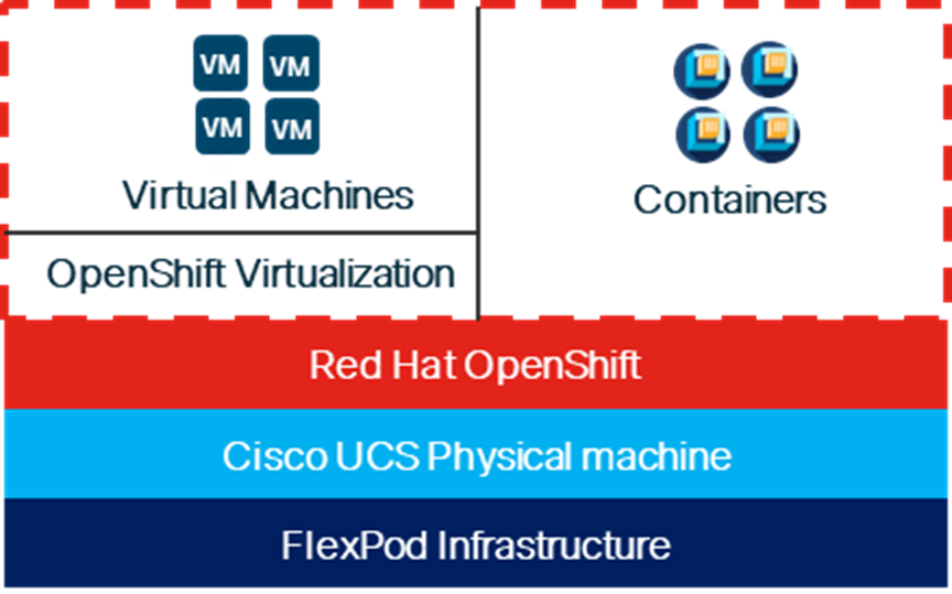
When Red Hat OpenShift Virtualization is added to a Red Hat OpenShift environment, both containers and VMs can now be run side-by-side on the same infrastructure as shown below. When applications are being containerized, if there are any issues with containerization of the application, the application can be left to run in a VM.
Figure 1. Containers and VMs in the Same Infrastructure
Solution Design
This chapter contains the following:
● FlexPod Multi-Tenant Configuration
● Red Hat OpenShift Virtualization
The FlexPod Datacenter with Cisco UCS and Cisco Intersight meets the following general design requirements:
● Resilient design across all layers of the infrastructure with no single point of failure
● Scalable design with the flexibility to add compute capacity, storage, or network bandwidth as needed
● Modular design that can be replicated to expand and grow as the needs of the business grow
● Flexible design that can support different models of various components with ease
● Simplified design with ability to integrate and automate with external automation tools
● Cloud-enabled design which can be configured, managed, and orchestrated from the cloud using GUI or APIs
To deliver a solution which meets all these design requirements, various solution components are connected and configured as explained in the following sections.
The FlexPod Datacenter solution with OpenShift Virtualization is built using the following hardware components:
● Cisco UCS X-Series Direct X9508 Chassis with Cisco UCSX-S9108-100G Fabric Interconnects, up to eight Cisco UCS X210C M7 Compute Nodes with 4th or 5th Generation Intel Xeon Scalable CPUs, and up to four Cisco UCS X440p PCIe Nodes each with up to two NVIDIA L40S GPUs (each X440p would go in place of an X210c)
● High-speed Cisco NX-OS-based Nexus 93600CD-GX switching design to support 100GE and 400GE connectivity
● NetApp AFF C800 end-to-end NVMe storage with 100G or 25G Ethernet
Note: Even though this solution validation was built with Cisco UCS X-Series Direct, all Cisco UCS components that support Red Hat CoreOS 4.17 on the Cisco UCS Hardware Compatibility List (HCL) are supported with this solution.
The software components of this solution consist of:
● Cisco Intersight to deploy, maintain, and support the Cisco UCS server components
● Cisco Intersight SaaS platform to maintain and support the FlexPod hardware components
● Cisco Intersight Assist Virtual Appliance to help connect NetApp ONTAP and Cisco Nexus switches with Cisco Intersight
● NetApp Active IQ Unified Manager to monitor and manage the storage and for NetApp ONTAP integration with Cisco Intersight
● Red Hat OpenShift to manage a Kubernetes containerized environment
● The Red Hat OpenShift Virtualization Operator to deploy and manage the OpenShift Virtualization environment
● The Red Hat Migration Toolkit for Virtualization Operator to migrate VMs from other virtualization environments to Red Hat OpenShift Virtualization or to migrate VMs between Red Hat OpenShift Virtualization environments
● NetApp Trident to provide persistent storage for VM disks
FlexPod Datacenter with OpenShift Virtualization
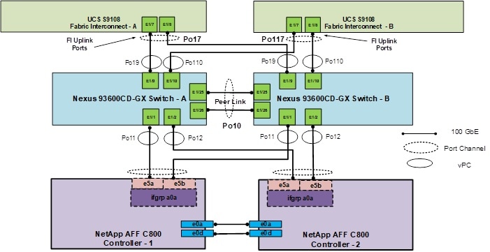
Figure 2 shows various hardware components and the network connections for the IP-based FlexPod design for FlexPod Datacenter with OpenShift Virtualization with Cisco UCS X-Series Direct.
Figure 2. FlexPod Datacenter Physical Topology for IP-based Storage Access with Cisco UCS X-Series Direct
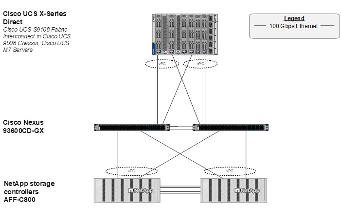
The reference hardware configuration includes:
● Two Cisco Nexus 93600CD-GX Switches in Cisco NX-OS mode provide the switching fabric.
● Two Cisco UCS S9108 Fabric Interconnects (FI) in the Cisco UCS X9508 chassis provide the chassis connectivity. Two 100 Gigabit Ethernet ports from each FI, configured as a Port-Channel, are connected to each Nexus 93600CD-GX.
● The Cisco UCS X9508 Chassis is also equipped with a pair of Cisco UCS 9416 X-Fabric modules to accommodate GPUs.
● One NetApp AFF C800 HA pair connects to the Cisco Nexus 93600CD-GX Switches using two 100 GE ports from each controller configured as a Port-Channel.
● Up to two NVIDIA L40S GPUs are installed in the Cisco UCS X440p cards and are connected to the Cisco UCS X210C M7 in the adjacent slot by X-Fabric.
● This reference configuration consists of 2 Cisco UCS X210c M7 servers each with an X440p card with 2 NVIDIA L40S GPUs, and 4 additional Cisco UCS X210c M7 servers.
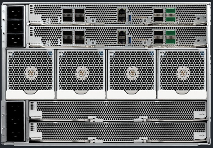
Note: It is important to note that the Cisco UCS S9108 FI is a fully functional FI with 8 100G ports as shown in Figure 3. The only difference between this FI and other FIs is the rules around how the ports can be configured. Currently, Cisco UCS C-Series servers and an additional X9508 chassis cannot be attached to the S9108 FI. All other FI policies can be applied to this FI in the same way as all the other FIs. In the datacenter, the Cisco UCS S9108 FIs provide a UCS Domain per X-Series Chassis. If using Cisco Intersight UCS Domain Profile Templates, all Cisco UCS S9108 Domains can be configured identically, and all servers behind the S9108s can be configured from a single pool.
Figure 3. Cisco UCS X9508 Chassis with 2 Cisco UCS S9108 FIs
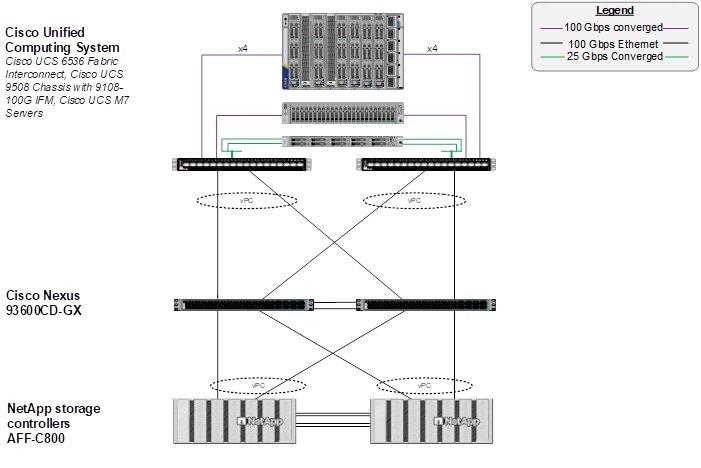
A standard FlexPod topology with a standalone FI such as the Cisco UCS 6536 FI as shown in Figure 4 is also fully supported for OpenShift Virtualization.
Figure 4. FlexPod Datacenter Physical Topology for IP-based Storage Access with Cisco UCS 6536 FI
FlexPod Multi-Tenant Configuration
In the deployment section of this document, FlexPod Datacenter with Red Hat OCP Bare Metal Manual Configuration with Cisco UCS X-Series Direct is first set up as a FlexPod tenant on top of FlexPod Base. This solution’s deployment layers OpenShift Virtualization on top of FlexPod Datacenter with Red Hat OpenShift on Bare Metal. With Red Hat OpenShift Virtualization, three Cisco virtual network interfaces (vNICs) are added, along with at least one VLAN for VM management. This VLAN is added to the Nexus switches, to the NetApp storage and to the UCS Domain Profile and worker node Server Profile.
Red Hat OpenShift Virtualization
Red Hat OpenShift Virtualization is layered onto a Red Hat OpenShift Bare Metal environment by installing and configuring the OpenShift Virtualization Operator and a HyperConverged Deployment as shown below. By default, the OpenShift Virtualization Operator is deployed in the openshift-cnv namespace and initial VMs can be configured there, but before VMs can be configured, VM networking and a place to store VMs will need to be set up.
OpenShift Virtualization VM Networking
In the Red Hat OpenShift Bare Metal environment, the NMState Operator was used to set up and maintain OpenShift server networking. With OpenShift Virtualization in this validation, NMState is used to create network bridges on vNICs added to the UCS Server Profiles for OpenShift Virtualization. Network Attachment Definitions (NADs) with specified VLAN tags and MTUs are then created on top of the bridges and attach VMs to the network.
Figure 5 illustrates that 3 vNICs (eno9, eno10, and eno11) are added to the Worker Server Profile Template in addition to the 4 vNICs that were used for OpenShift on Bare Metal. vNIC eno9 is used for VM front end connectivity and multiple VLANs can be configured on that vNIC. It is required that those VLANs are configured in the Cisco Nexus switches and also in the Cisco UCS Domain Profile VLAN policy and in the Ethernet Network Group policy attached to the vNIC in the LAN Connectivity policy. This vNIC is configured with Cisco UCS Fabric Failover which will fail the vNIC over to the other FI in case of an FI failure or reboot. vNICs eno10 and eno11 are identical to vNICs eno6 and eno7 and provide VM in-guest iSCSI and NVMe-TCP connectivity. These vNICs do not have Fabric Failover configured. Additional iSCSI and NVMe-TCP VLANs can be added to these vNICs in the same way VLANs are added to vNIC eno9. NMState Bridges are configured on eno9, eno10, and eno11 using Node Network Configuration Policies (NNCPs). Then, Network Attachment Definitions (NADs) are added, specifying the VLAN tag and the MTU (if 9000). VM NICs then reference the NAD and are attached to the correct VLAN. NADs configured in the default namespace or project are globally available to VMs in any namespace. NADs can also be configured in a specific namespace and are then only visible to VMs in that namespace. All three of the added vNICs use the Ethernet Adapter policy with 16 RX queues and Receive Side Scaling (RSS) enabled to allow the RX queues to be serviced by different CPU cores.
Figure 5. OpenShift Virtualization VM Attachment to the Network

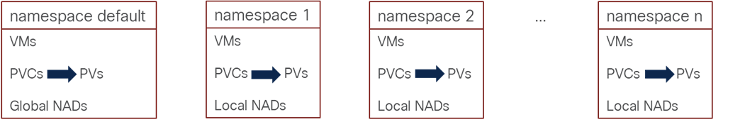
Grouping and Separating VMs with namespaces or Projects
VMs can be created in the default openshift-cnv namespace or project, or in any other namespace. Using namespaces in this way allows VMs to be both grouped together and separated from other VMs. Figure 6 shows this grouping. With respect to NADs, as described above, NADs created within the default namespace are globally visible to VMs, where NADs created within other namespaces are only visible to VMs within that namespace. Storage persistent volume claims (PVCs) for VM disks are also contained within the namespace, but it is important to note that the corresponding persistent volumes (PVs) are tracked at the cluster level and not within namespaces.
Figure 6. VM Grouping and Separation Using namespaces
VM Disk Storage with NetApp Trident
Just as in the FlexPod OpenShift with Bare Metal CVD, persistent storage for VM disks is provided by NetApp Trident. NFS, iSCSI, and NVMe-TCP storage can be provided by Trident. Live Migration requires that storage be configured with the ReadWriteMany access mode which NFS provides by default. With NetApp ONTAP iSCSI and NVMe-TCP, ReadWriteMany can be configured by using the Block volume mode instead of Filesystem, allowing VMs to be migrated. Previous iterations of this document described an issue with Live Migration of VMs with NVMe-TCP disks. That issue has been resolved, but it is important that when OpenShift was configured that each node with the worker role is provisioned with a unique NVMe NQN, and that minimally Trident version 25.6.2 is used. It is important to note that with OpenShift Virtualization, each VM disk is stored in a separate volume in the NetApp storage, as opposed to the VMware vSphere environment where many VMs and their disks are stored within a datastore volume.
Data Protection of VMs using Trident Protect
NetApp Trident protect software provides advanced application data management capabilities that enhance the functionality and availability of stateful Kubernetes applications backed by NetApp ONTAP storage systems and the NetApp Trident CSI storage provisioner. Trident protect simplifies the management, protection, and movement of containerized workloads across public clouds and on-premises environments. It also offers automation capabilities through its Kubernetes-native API and powerful tridentctl-protect CLI.
Virtual machines in the OpenShift Virtualization environment are containerized applications that run in the worker nodes of OpenShift Container platform. It is important to protect the VM metadata as well as the persistent disks of the VMs, so that when they are lost or corrupted, you can recover them. The persistent disks of the OpenShift Virtualization VMs can be backed by ONTAP storage integrated to the OpenShift Cluster using Trident CSI. Trident protect enables snapshots, backups, restore, and disaster recovery of applications and VMs on an OpenShift cluster. For OpenShift Virtualization VMs, data that can be protected with Trident protect include Kubernetes resource objects associated with the VMs, persistent volumes, and internal images. In this solution, Trident protect is used to create snapshots and backups of VMs including its data volumes to ONTAP S3 Object Storage. We then restore from a snapshot or a backup when needed.
VM Migration into OpenShift Virtualization
The OpenShift Migration Toolkit for Virtualization allows VMs to be imported from VMware vSphere and Red Hat OpenStack into OpenShift as well as migrating OpenShift VMs between clusters. VMs for OVA format can also be imported. In this validation, VMware vSphere VMs were imported to OpenShift. Only RHEL 8 and 9 and Windows VMs were successfully imported. It was also found that VMs with SCSI disk controllers (preferably VMware paravirtual disk controllers) would successfully migrate. VMs with NVMe based disk controllers would migrate but could not be successfully started in OpenShift. All migrated VMs were brought into OpenShift with both virtio network interfaces and virtio disk controllers. In this migration, Windows 11 VMs (which are required to be encrypted in VMware) could not successfully be migrated to Openshift VMs. It was also found that it is best to set up a direct Layer 2 (in the same VLAN) connection between the VMware ESXi hosts and OpenShift nodes for VM disk migration.
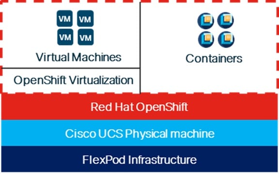
FlexPod Base was first setup on the infrastructure shown in Figure 7. Then FlexPod Datacenter with Red Hat OpenShift on Bare Metal was installed as a tenant on top of FlexPod Base. Next, OpenShift Virtualization was installed and configured on top of OpenShift on Bare Metal along with the OpenShift Migration Toolkit for Virtualization. This results in a single modern platform that supports both containerized applications and VMs. In the journey to containerization, if an application cannot be fully containerized, the VM is a fallback for that application.
Figure 7. A Single Environment for both Containers and VMs
Solution Deployment
This chapter contains the following:
● Deploy OpenShift Virtualization
Note: The NetApp storage controller and disk shelves should be connected according to best practices for the specific storage controller and disk shelves. For disk shelf cabling, go to NetApp Support: https://docs.netapp.com/us-en/ontap-systems/index.html
Table 1 lists VLANs configured for setting up the FlexPod environment along with their usage.
| VLAN ID |
Name |
Usage |
IP Subnet used in this deployment |
| 2 |
Native-VLAN |
Use VLAN 2 as native VLAN instead of default VLAN (1). |
|
| 1020 |
OOB-MGMT-VLAN |
Out-of-band management VLAN to connect management ports for various devices |
10.102.0.0/24; GW: 10.102.0.254 |
| 1022 |
OCP-BareMetal-MGMT |
OpenShift Bare Metal or Management VLAN for the Openshift Nodes and Cluster |
10.102.2.0/24; GW: 10.102.2.254 |
| 1023* |
VM-MGMT |
OpenShift VM Management VLAN – for VM front end interfaces |
10.102.3.0/24; GW: 10.102.3.254 |
| 3052 |
OCP-NFS |
NFS VLAN for persistent storage |
192.168.52.0/24 ** |
| 3012 |
OCP-iSCSI-A |
iSCSI-A path for persistent storage |
192.168.12.0/24 ** |
| 3022 |
OCP-iSCSI-B |
iSCSI-B path for persistent storage |
192.168.22.0/24 ** |
| 3032 |
OCP-NVMe-TCP-A |
NVMe-TCP-A path for persistent storage |
192.168.32.0/24 ** |
| 3042 |
OCP-NVMe-TCP-B |
NVMe-TCP-B path for persistent storage |
192.168.42.0/24 ** |
* Added for OpenShift Virtualization. All other VLANs were already added in OpenShift on Bare Metal.
** IP gateway is not needed since no routing is required for these subnets
Note: S3 object storage was also used in this environment but requires a routable subnet. In order to avoid having two default gateways on the OpenShift nodes, S3 was placed on the OCP-BareMetal-MGMT subnet and VLAN. A separate VLAN and subnet was not defined for S3.
Table 2 lists the software revisions for various components of the solution.
| Layer |
Device |
Image Bundle |
Comments |
| Compute |
Cisco UCS |
4.3(5.240032) |
Cisco UCS GA release for infrastructure including FIs and IFM |
| Cisco UCS X210C M7 |
5.3(0.250001) |
|
|
| GPU |
NVIDIA L40S |
570.124.06 |
|
| Network |
Cisco Nexus 93600CD-GX NX-OS |
10.4(4)M |
|
| Storage |
NetApp AFF C800 |
ONTAP 9.16.1 |
Latest patch release |
| Software |
Red Hat CoreOS |
4.17 |
Latest patch release |
| Red Hat OpenShift |
4.17 |
Latest patch release |
|
| NetApp Trident |
25.06.6 |
|
|
| NetApp Trident protect |
25.06.0 |
|
The information in this section is provided as a reference for cabling the physical equipment in a FlexPod environment. To simplify cabling requirements, a cabling diagram was used.
The cabling diagram in this section contains the details for the prescribed and supported configuration of the NetApp AFF C800 running NetApp ONTAP 9.16.1.
Note: For any modifications of this prescribed architecture, see the NetApp Interoperability Matrix Tool (IMT).
Note: This document assumes that out-of-band management ports are plugged into an existing management infrastructure at the deployment site. These interfaces will be used in various configuration steps.
Note: Be sure to use the cabling directions in this section as a guide.
The NetApp storage controller and disk shelves should be connected according to best practices for the specific storage controller and disk shelves. For disk shelf cabling, go to NetApp Support.
Figure 8 details the cable connections used in the validation lab for the FlexPod topology based on the Cisco UCS S9108 fabric interconnect installed in the Cisco UCS X9508 chassis. Two 100Gb links connect each Cisco UCS Fabric Interconnect to the Cisco Nexus Switches and each NetApp AFF controller to the Cisco Nexus Switches. Additional 1Gb management connections will be needed for out-of-band network switches that sit apart from the FlexPod infrastructure. Each Cisco UCS fabric interconnect and Cisco Nexus switch is connected to the out-of-band network switches, and each AFF controller has a connection to the out-of-band network switches. Layer 3 network connectivity is required between the Out-of-Band (OOB) and In-Band (IB) Management Subnets. This cabling diagram shows the iSCSI-boot configuration.
Figure 8. FlexPod Cabling with Cisco UCS 6536 Fabric Interconnect
Procedure 1. Deploy FlexPod with OpenShift on Bare Metal
Step 1. Using the information in the above tables and diagrams, use FlexPod Datacenter Base Configuration using IaC with Cisco IMM and NetApp ONTAP or FlexPod Datacenter Base Manual Configuration with Cisco IMM and NetApp ONTAP to deploy the Base FlexPod.
Step 2. Use FlexPod Datacenter with Red Hat OpenShift Bare Metal IaC Configuration with Cisco UCS X-Series Direct or FlexPod Datacenter with Red Hat OCP Bare Metal Manual Configuration with Cisco UCS X-Series Direct to deploy Red Hat OpenShift with Bare Metal on the environment.
Deploy OpenShift Virtualization
Use the following procedures to add OpenShift Virtualization to the OpenShift on Bare Metal environment.
Procedure 1. Configure Nexus Switches for the OpenShift Virtualization
Step 1. Run the following commands to add at least one VLAN with a routable subnet for VM management connections. Also, optionally add NTP distribution interfaces in this subnet. Execute these steps in an ssh session on both switches.
config t
vlan 1023
name OCP-VM-MGMT
exit
int Po10,Po19,Po110,Po127 # Po127 is switch uplink port channel
switchport trunk allowed vlan add 1023 # Add OCP-VM-MGMT VLAN to vPC peer link, FI, and uplink port channels
exit
vrf context OCP-VM-MGMT
description VRF for routing OCP-VM-MGMT subnets/VLANs
ip route 0.0.0.0/0 10.102.3.254
interface VLAN1023
vrf member OCP-VM-MGMT
ip address 10.102.3.3/24 # Use 10.102.3.4/24 in the second switch
no shutdown
exit
copy r s
Procedure 2. Configure Cisco UCS IMM for OpenShift Virtualization
Use the following steps to add the OCP-VM-MGMT VLAN and three vNICs to IMM. Execute these steps from Cisco Intersight.
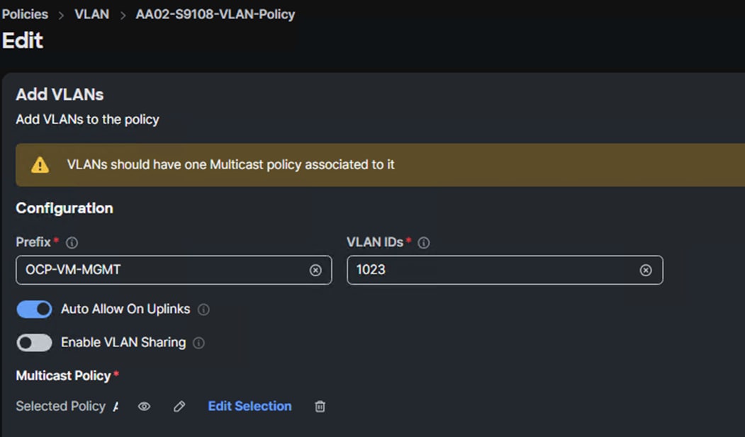
Step 1. In Cisco Intersight, select Configure > Policies. Add a Filter of Type VLAN. Select and edit the UCS Domain VLAN policy (for example, AA02-S9108-VLAN). Click Next. As you did when building the FlexPod, add the OCP-VM-MGMT VLAN to the policy. Click Save to save the policy.
Step 2. In Cisco Intersight, select Configure > Profiles > UCS Domain Profiles. The FI Domain Profile should show a Status of Not Deployed Changes.
![]()
Step 3. Click the three dots to the right of the UCS Domain Profile and select Deploy and then Deploy again. The VLAN will be added to the configuration of the FIs, and the Status will change to OK.
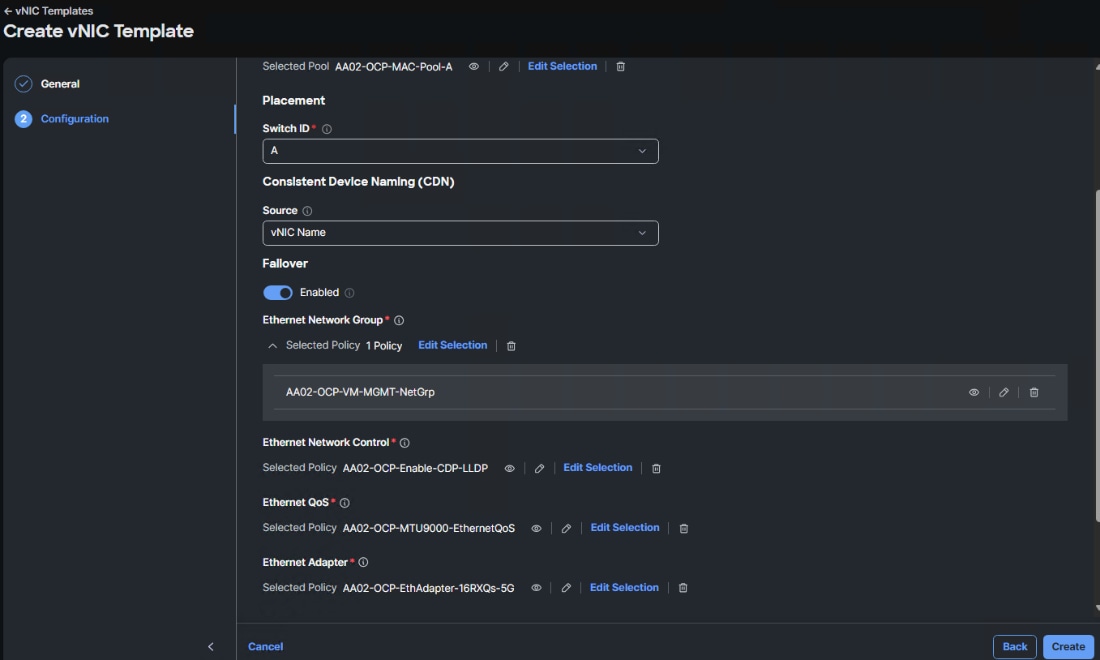
Step 4. In Cisco Intersight, select Configure > Templates > vNIC Templates. Click Create vNIC Template. Select the correct Organization (for example, AA02-OCP) and name the template OCP-VM-MGMT. Click Next.
Step 5. The interface will be placed on Fabric A with Fabric Failover enabled. Under MAC Pool, select MAC-Pool-A. Leave Switch ID set to A. Leave the CDN Source set to vNIC Name. Enable Failover.
Step 6. Under Ethernet Network Group, click Select Policies and then click Create New. Make sure the correct Organization is selected and name the policy (for example, AA02-OCP-VM-MGMT-NetGrp). Click Next.
Step 7. Click Add VLANs then select Enter Manually. VLANs can be entered in a comma-separated list. Enter all VLANs that you want to attach VMs to with the exception of the iSCSI and NVMe-TCP VLANs. Click Enter. Do not set a Native VLAN in this policy. When all VLANs have been added, click Create to create the policy.
Note: All VLANs entered here should also be entered in the FI VLAN policy above and on the Nexus switch ports connected to the FI uplink ports.
Step 8. Select the policy just created and click Select. Under Ethernet Network Control, click Select Policy and select the already created policy (for example, AA02-OCP-Enable-CDP-LLDP). Under Ethernet QoS, click Select Policy and select the MTU9000 policy. Under Ethernet Adapter, click Select Policy and select the appropriate 16RXQs policy. Do not select a policy under iSCSI Boot. After all policies have been selected, click Create to create the vNIC Template.
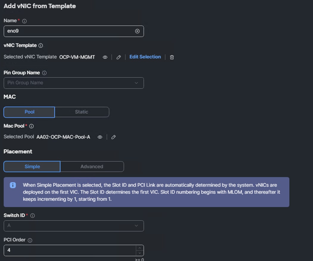
Step 9. In Cisco Intersight, select Configure > Policies. Add a Filter of Type LAN Connectivity. Select and edit the appropriate Worker LAN Connectivity Policy for worker nodes running OpenShift Virtualization. Click Next. From the Add drop-down list, select a vNIC from Template. Name the vNIC eno9 and click Select vNIC Template. Select the OCP-VM-MGMT vNIC Template created above and click Select. Enter 4 for PCI Order. Click Add.
Step 10. Add vNIC eno10 with the same “OCP-iSCSI-NVMe-TCP-A-vNIC” template used for eno6 and PCI Order 5. Also, add vNIC eno11 with the same “OCP-iSCSI-NVMe-TCP-B-vNIC” template used for eno7 and PCI Order 6. When all 3 vNICs are added, click Save & Deploy followed by Save & Proceed.
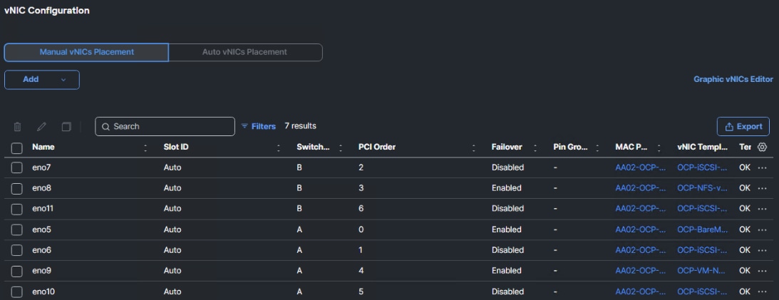
Step 11. Adding vNICs will require a server reboot, enable Reboot Immediately to Activate and click Deploy. Wait for all servers to reboot successfully.
Deploy OpenShift Virtualization
Procedure 1. Deploy the OpenShift Virtualization Operator
Step 1. In the OpenShift console, select Operators > OperatorHub. In the search box, type Virtualization. Select OpenShift Virtualization provided by Red Hat.
Step 2. Click Install. Click Install again to deploy OpenShift Virtualization in the openshift-cnv namespace.
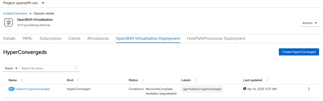
Step 3. Once the operator is installed, click Create Hyperconverged. Scroll down and click Create.
Step 4. Refresh the web console as required and wait for the kubevirt-hyperconverged status to become Conditions: ReconcileComplete, Available, Upgradeable.

Step 5. Connect and log into the RHEL Activation Keys page in the Red Hat Hybrid Cloud Console at https://console.redhat.com/insights/connector/activation-keys#SIDs=&tags=. If an appropriate Activation Key is not present and if your user permissions allow, use Create activation key to create a RHEL Activation Key for OpenShift Virtualization automatic subscription activation for RHEL VMs. Note the Key Name and Organization ID.
Step 6. In the OpenShift Console, select Virtualization > Overview > Settings. Expand Guest management and then expand Automatic subscription of new RHEL VirtualMachines. Fill in the Activation key and Organization ID and click Apply. Optionally, turn on Enable auto updates for RHEL VirtualMachines to enable automatic updates on all RHEL VMs and turn on Enable guest system log access to enable access to the VM guest system logs.
Procedure 2. Configure VM Network Connectivity
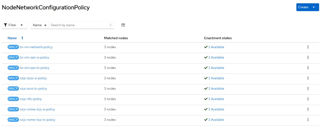
In this lab validation, virtual machines are connected to the network with NMState NodeNetworkConfigurationPolicy (NNCP) bridges and NetworkAttachmentDefinitions (NAD). A bridge interface can be created on a network interface (bond or NIC) that supports multiple allowed VLANs. An NAD can then be created with a VLAN tag and the MTU can be specified. The VM NIC is then connected to the NAD. Earlier, 3 vNICs (one for VM front-end networks and 2 for in-guest iSCSI and NVMe-TCP) were added to the worker nodes. Three NNCP bridges will be created, and NADs will be created on top of these. NADs created in the default namespace are available for VMs in any namespace. NADs can also be created in individual namespaces and are only available for VMs in that namespace.
Step 1. On the OpenShift installer VM, in the NMState directory, create the following YAML files:
apiVersion: nmstate.io/v1
kind: NodeNetworkConfigurationPolicy
metadata:
name: br-vm-network-policy
spec:
nodeSelector:
node-role.kubernetes.io/worker: ''
desiredState:
interfaces:
- name: br-vm-network
description: Linux bridge with eno9 as a port
type: linux-bridge
state: up
ipv4:
enabled: false
ipv6:
enabled: false
bridge:
options:
stp:
enabled: false
port:
- name: eno9
cat iscsi-nvme-a-bridge.yaml
apiVersion: nmstate.io/v1
kind: NodeNetworkConfigurationPolicy
metadata:
name: br-vm-san-a-policy
spec:
nodeSelector:
node-role.kubernetes.io/worker: ''
desiredState:
interfaces:
- name: br-vm-san-a
description: Linux bridge with eno10 as a port
type: linux-bridge
state: up
ipv4:
enabled: false
ipv6:
enabled: false
bridge:
options:
stp:
enabled: false
port:
- name: eno10
cat iscsi-nvme-b-bridge.yaml
apiVersion: nmstate.io/v1
kind: NodeNetworkConfigurationPolicy
metadata:
name: br-vm-san-b-policy
spec:
nodeSelector:
node-role.kubernetes.io/worker: ''
desiredState:
interfaces:
- name: br-vm-san-b
description: Linux bridge with eno11 as a port
type: linux-bridge
state: up
ipv4:
enabled: false
ipv6:
enabled: false
bridge:
options:
stp:
enabled: false
port:
- name: eno11
Step 2. Create the bridge interfaces:
oc create -f vm-network-bridge.yaml
oc create -f iscsi-nvme-a-bridge.yaml
oc create -f iscsi-nvme-b-bridge.yaml
Step 3. In the OpenShift Console, select Networking > NodeNetworkConfigurationPolicy. The three bridges should now be listed and should be pushed out to the worker nodes.
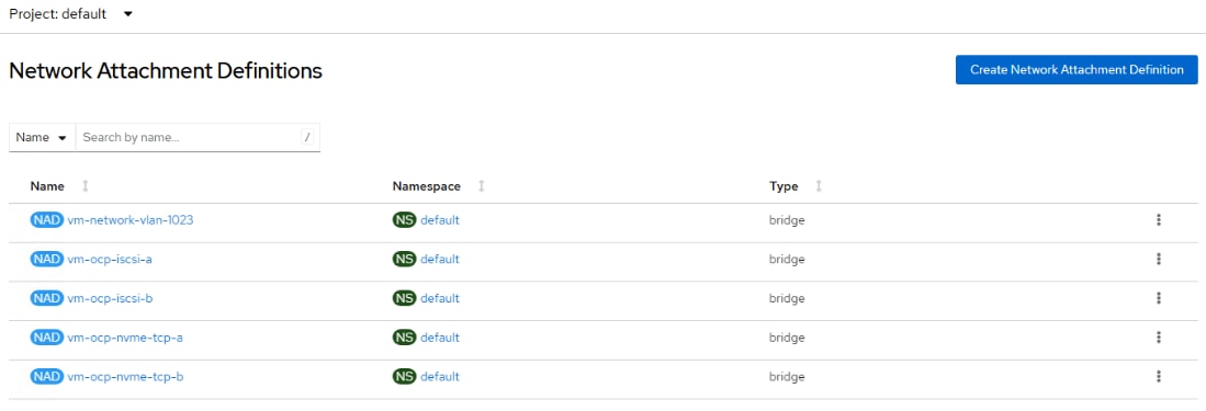
Step 4. Select Networking > NetworkAttachmentDefinitions. At the top of the page, select the default Project. On the right, click Create Network Attachment Definition. In our example, we are creating a VM network attachment on VLAN 1023. The Name is vm-network-vlan-1023. For Network Type, select Linux bridge. For Bridge name, enter br-vm-network. For VLAN tag number, enter 1023. Uncheck the MAC spoof check checkbox. Click Create.

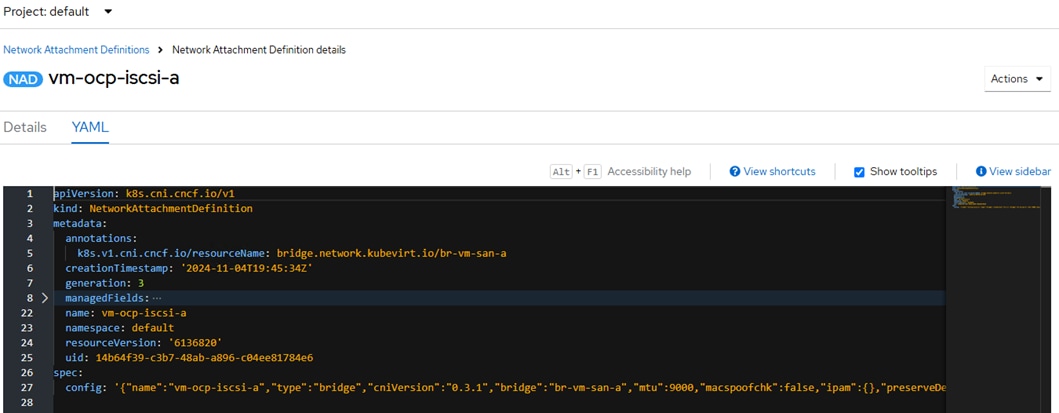
Step 5. As required, create Network Attachment Definitions for iSCSI A and B and for NVMe-TCP A and B. For the iSCSI definitions, do not specify a VLAN since the iSCSI VLANs are the native VLANs for those vNICs. For each of the in-guest iSCSI and NVMe-TCP interfaces, select the NAD and in the Network Attachment Definition details, select the YAML tab. In the YAML tab, on the next to last config line, add “mtu”:9000, as shown in the screenshot. Click Save.
Step 6. Add any additional need VM Network Attachment Definitions.
Procedure 3. Add Framework for vTPM
Microsoft Windows 11 has a requirement for a Trusted Platform Module (TPM) in the machine. With Red Hat OpenShift Virtualization, a virtual TPM (vTPM) can be added to a VM. A virtual Trusted Platform Module (vTPM) device functions like a physical Trusted Platform Module (TPM) hardware chip. You can use a vTPM device with any operating system, but Windows 11 requires the presence of a TPM chip to install or boot. A vTPM device allows VMs created from a Windows 11 image to function without a physical TPM chip. If you do not enable vTPM, then the VM does not recognize a TPM device, even if the node has one.
A vTPM device also protects virtual machines by storing secrets without physical hardware. OpenShift Virtualization supports persisting vTPM device state by using Persistent Volume Claims (PVCs) for VMs. You must specify the storage class to be used by the PVC by setting the vmStateStorageClass attribute in the HyperConverged custom resource (CR). The storage class must be of type Filesystem and support the ReadWriteMany (RWX) access mode. Currently, with NetApp Trident, only the NFS storage class supports these parameters.
Step 1. On the OpenShift Installer VM, edit the HyperConverged custom resource.
oc edit hyperconverged kubevirt-hyperconverged -n openshift-cnv
Step 2. Scroll down to the “spec:” section and add the following with the nfs storage class name.
spec:
vmStateStorageClass: <storage_class_name>
Step 3. Save the HyperConverged custom resource with “:x” (vim save).
Step 4. Later, a vTPM can be added to a VM by editing the VM with:
oc edit vm <vm_name> -n <namespace>
Step 5. Under devices: add the vTPM with:
devices:
tpm:
persistent: true
Step 6. Save the updated VM specification with “:x.” To remove the vTPM, set “persistent:” to false.
Note: Currently it is not possible to take a VM snapshot when a vTPM and persistent EFI is attached to the VM. The vTPM and persistent EFI can be removed from the VM to take a snapshot, or a PVC snapshot can be taken.
Procedure 4. Create a RHEL VM
For Red Hat Enterprise Linux (RHEL) 8 and 9, Fedora, and CentOS Stream 9 VMs, a VM disk image is already loaded by default. In the OpenShift Console, check Virtualization > Overview > Settings > General settings > Automatic images download to verify that these images are downloaded automatically. Red Hat recommends not installing VMs in the openshift-cnv namespace. VMs can be created in the default namespace or in any other namespace. Namespaces can be used to group and separate VMs, and specific Network Attachment Definitions can be created within a namespace and only used by VMs within that namespace.
Note: The default VM images are stored as Volume Snapshots in the openshift-virtualization-os-images namespace or project. A Volume Snapshot Class must be defined for these images to be downloaded.
Note: The default VM images are downloaded using the current default storage class. This same storage class must be used when building VMs from these images. A VM image with one storage class cannot be used to build a VM disk in a different storage class.
Step 1. In the OpenShift Console, select Virtualization > VirtualMachines. Select Project: default or use any other custom project or namespace where you want to place the VM. If using a custom project or namespace, create any specific Network Attachment Definitions within that namespace, remembering that the VLANs used in those Network Attachment Definitions need to be configured in the Cisco Nexus switches, in the Cisco UCS Fabric Interconnects VLAN policy, and in the Cisco UCS vNIC Ethernet Network Group policy.
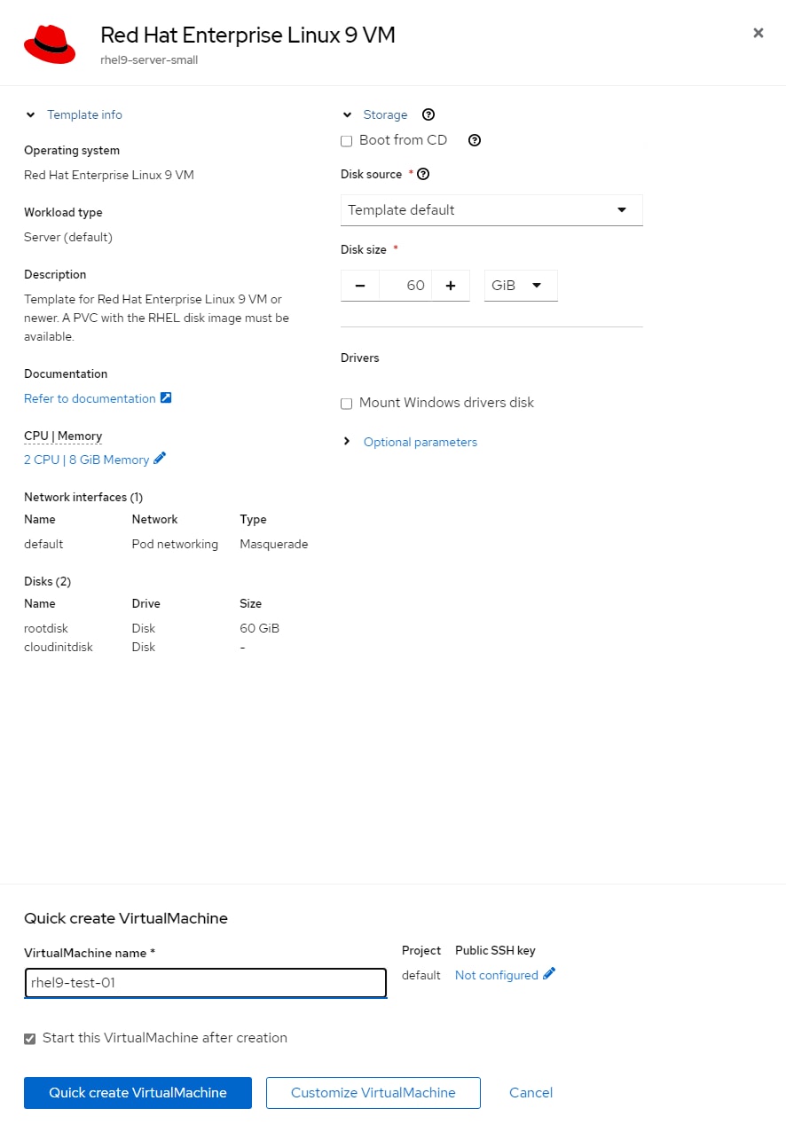
Step 2. Click the Create VirtualMachine drop-down list and select From template. Click Red Hat Enterprise Linux 9 VM.
Step 3. Do not select Boot from CD. Also, leave Disk source set to Template default. Adjust the Disk size, as necessary. Adjust CPU|Memory, as necessary. Click Optional Parameters and adjust, as necessary. Change the VirtualMachine name and click Customize VirtualMachine.
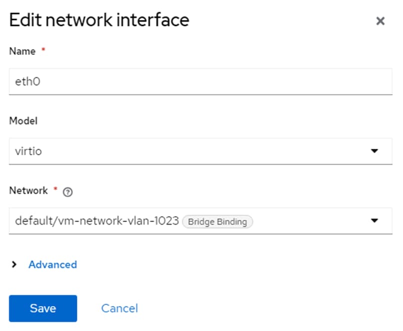
Step 4. On the Customize and create VirtualMachine page, select the Network Interfaces tab. Click the three dots to the right of the default network interface and select Edit. Change the Name of the network interface if desired and from the Network drop-down list, select an appropriate Network Attachment Definition. Add any additional network interfaces as needed. Click Save.
Step 5. Click the Disks tab and adjust, as necessary.
Step 6. Click the Scripts tab. Edit Cloud-init, select Script and adjust as necessary (for example, add “ssh_pwauth: True” right after the password line in the script to allow ssh password authentication login). Click Save and Apply.
Step 7. Once all tabs have been reviewed, click Create VirtualMachine.
Step 8. Once the VM has been Provisioned and Started, click the Console tab. You can click Guest login credentials to see the default user name and password. This user has sudo privileges. Login and configure the VM. If you configured the automatic subscription key insertion, you can use “sudo dnf” to add and upgrade packages.
Step 9. To clone the VM, go to Virtualization > VirtualMachines > VirtualMachine details, and from the Actions drop-down list, select Clone. Give the VM a new name, which will be configured as the new hostname by CloudInit and select the checkbox for Start VirtualMachine once created. Click Clone.
Procedure 5. Create a Windows VM Template (Windows Server 2025)
For Windows VMs first time creation, a Windows Installation ISO and installation key are needed. Once the first VM for a given version of windows is created, the boot disk can be stored as a boot image to create more VMs in the future. In this example, Windows Server 2025 Standard will be installed and a user template created.
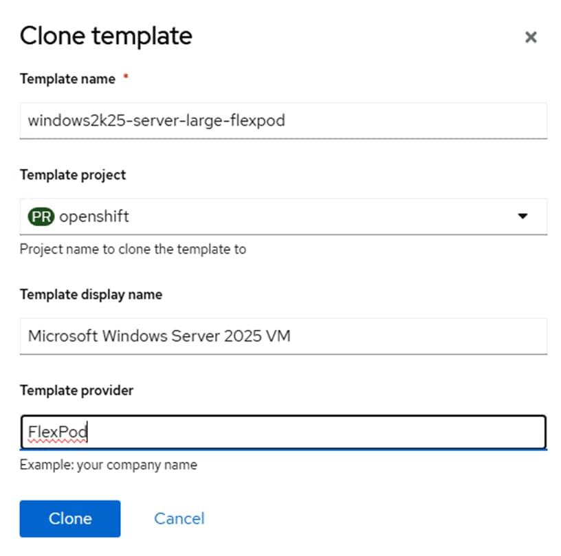
Step 1. In the OpenShift Console, select Virtualization > Templates. Select the openshift Project. Scroll down until you see windows2k25-server-large. Click the three dots to the right of windows2k25-server-large and select Clone.
Step 2. Give the template a descriptive name and select a project where you will store many VMs (for example, default). You can add your Company name for Template provider. Click Clone.
Step 3. The default Windows 11, Windows Server 2022, and Windows Server 2025 templates contain a vTPM by default. Windows 11 requires a vTPM for installation, but Windows Server 2022 and 2025 will install without a vTPM in the configuration. In Windows Server 2022 and 2025, a vTPM is only required if Bitlocker is deployed. At this time, a VM snapshot will fail for any VM that has a vTPM or persistent EFI. To avoid this issue, remove the vTPM and persistent EFI from the Template just created. Select the YAML tab. Scroll down to lines 190 and 191 and delete those lines. Then scroll down further to line 212 and change persistent: true to persistent: false. Click Save and then Reload.


Step 4. Select the Network interfaces tab. Click the three dots to the right of the default interface and select Edit. Change the Model to virtio and optionally select a more appropriate setting for Network. Click Save.
Step 5. Select the Disks tab. Click the three dots to the right of the rootdisk and select Edit. Change the interface from SATA to VirtIO and click Save.
Step 6. In the OpenShift Console, select Virtualization > VirtualMachines. Select Project: default or use any other custom project or namespace where you want to place the VM. If using a custom project or namespace, create any specific Network Attachment Definitions within that namespace, remembering that the VLANs used in those Network Attachment Definitions need to be configured in the Cisco Nexus switches, in the Cisco UCS Fabric Interconnects VLAN policy, and in the vNIC Ethernet Network Group policy.
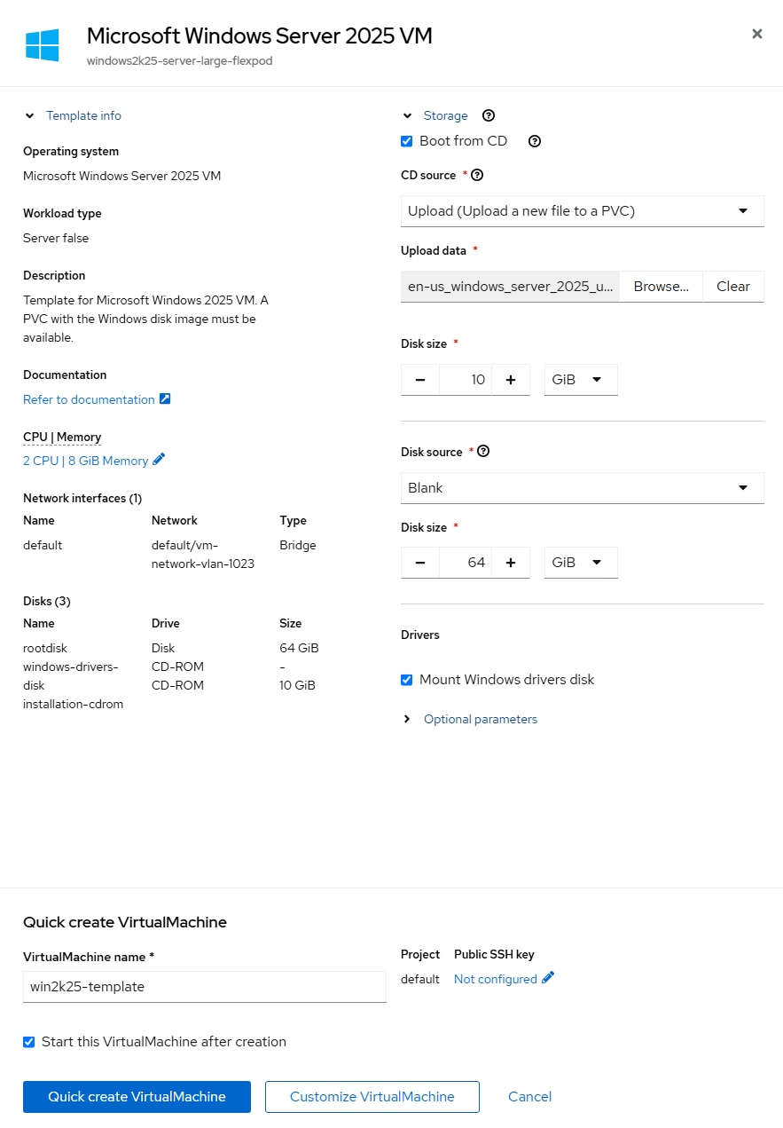
Step 7. From the Create drop-down list and select From template. Under Template project, select User Templates. Click the Microsoft Windows Server 2025 VM template created above.
Step 8. Select Boot from CD. For CD source, from the drop-down list select Upload (Upload a new file to a PVC). Click Browse and browse to and Open the Windows Server 2025 ISO. Adjust the CD Disk size as necessary to be a little larger than the ISO. Leave Disk source set to Blank and leave Disk size set to 64GiB. Make sure Mount Windows drivers disk is selected. Change the VirtualMachine name to something like win2k25-template and click Customize VirtualMachine.
Step 9. If you get an Invalid certificate error, click the URL, click Advanced and then click Continue to cdi-uploadproxy…. When you get to the message “This page isn’t working,” close the window. Click Customize VirtualMachine again. Wait a few minutes for the ISO to be uploaded to a PVC.
Step 10. On the Customize and create VirtualMachine page, select the Network Interfaces tab. If anything needs to be changed about the network interface, click the three dots to the right of the interface and select Edit.
Step 11. Click the Disks tab and using the three dots to the right of rootdisk, click Edit. If a Storage Class other than the default storage class is desired for the disk, select the new Storage Class. Click Save.
Note: For Windows, if virtio is used for rootdisk, it is critical that the windows-drivers-disk is mounted so that the virtio driver can be loaded during the installation process.

Step 12. Once all tabs have been reviewed, click Create VirtualMachine.
Step 13. Once the VM has been Provisioned and Started, click the Console tab. Click on the console window and hit a key when you see “Press any key to boot from CD or DVD…”
Step 14. Select the appropriate Language and Time and currency format and click Next.
Step 15. Select the appropriate keyboard and click Next.
Step 16. Select the “I agree everything…” checkbox and click Next.
Step 17. Enter a valid product key and click Next.
Step 18. Select Windows Server 2025 Standard (Desktop Experience) and click Next.
Step 19. Click Accept.
Step 20. If you selected the virtio rootdisk, click Load driver. Click Browse. Expand the virtio-win CD Drive. Expand amd64 and select the 2k25 folder. Click OK. Select “Red Hat VirtIO SCSI controller” and click Install.
Step 21. If you get the error stating “Microsoft Server Operating System can’t be installed on this drive. (Show details),” click on the error link. Click OK to get the drive online.
Step 22. Select Drive 0 Unallocated Space and click Next.
Step 23. Click Install.
Step 24. The Windows installation will complete and do not hit a key to boot from CD or DVD when the VM reboots. The VM will reboot more than once.
Step 25. Enter and confirm an Administrator password and click Finish.
Step 26. From the Send key drop-down list, send Ctrl + Alt + Delete to the VM. Enter the Administrator password to login.
Step 27. Click Accept.
Step 28. Close Server Manager. Use the Folder icon in the Task Bar to open File Explorer. Select CD Drive virtio-win on the left. Scroll down and double-click virtio-win-guest-tools. Select the checkbox to agree to the license terms and conditions and click Install. Complete the installation. Reboot the VM.
Step 29. Log back into the VM and if necessary configure the network interface. Type update in the search box, select Check for updates, install all Windows updates, and restart the VM.
Step 30. Log back into the VM and make any other adjustments, such as setting the VM timezone and time. Then, from the VirtualMachine details > Actions drop-down list to Stop the VM.
Step 31. Select the Configuration tab. On the left, select Storage. Uncheck “Mount Windows drivers disk.” Using the three dots to the right of the installation-cdrom, select Detach. Choose whether to delete the installation-cdrom PVC (it can be used for other installations) and click Detach. The rootdisk should now be the VM’s only disk and it should show bootable.
Step 32. From the Actions drop-down list, start the VM. Select the Console tab. Log into the VM.
Step 33. Optionally, use a command-line window and diskpart to delete the rootdisk Recovery Partition 4. Open Disk Management and extend the C: volume to the end of the disk.
Step 34. Open File Explorer and navigate to This PC\C:\Windows\System32\Sysprep. Double-click sysprep. Select Generalize. Change the Shutdown Options to Shutdown and click OK. The VM will shut down. When the VM begins to Start, from the Actions drop-down list select Stop.
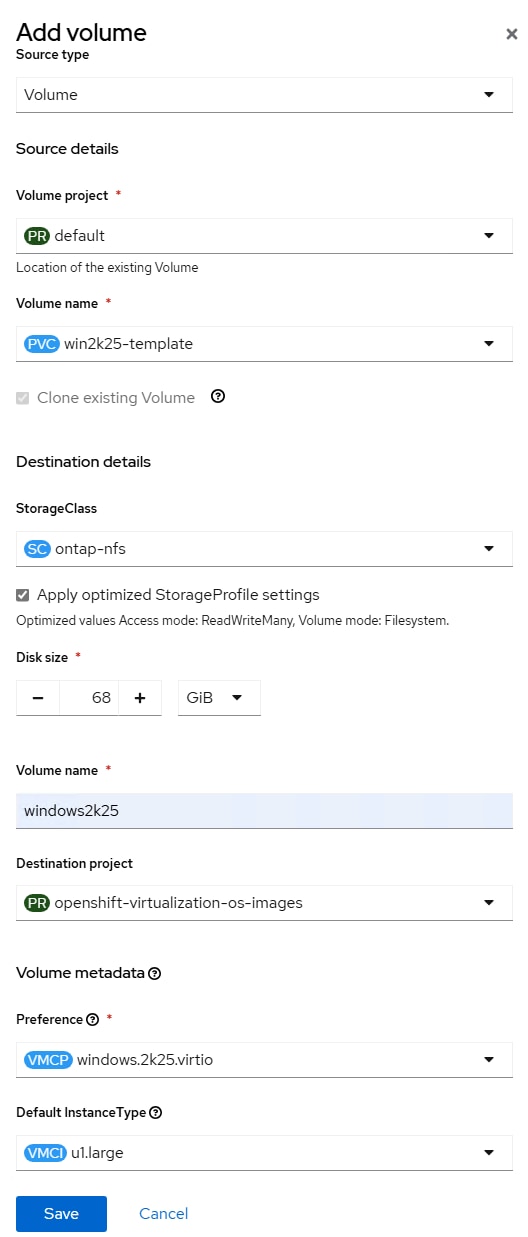
Step 35. To create a Windows Server 2025 Standard Bootable volume, select Virtualization > Bootable volumes. Switch to the openshift-virtualization-os-images Project. Make sure windows2k25 is not listed. If windows2k25 is listed, delete it. Use the Add volume drop-down list to select With form. For Source type, select Use existing volume. For PVC project, select default or the project where the Windows Server 2025 VM is located. For PVC name, select the PVC for the Windows Server 2025 VM rootdisk. Select the appropriate StorageClass. Do not change the disk size. For volume name, enter windows2k25. For Destination project, select openshift-virtualization-os-images. For Preference, select windows.2k25.virtio. For DefaultInstanceType, select Red Hat provided > U series > large: 2 CPUs, 8 GiB Memory or an appropriate DefaultInstanceType. Click Save.
Step 36. The windows2k25 Data Source should now appear under Bootable volumes. Wait for the Clone in Progress to complete.
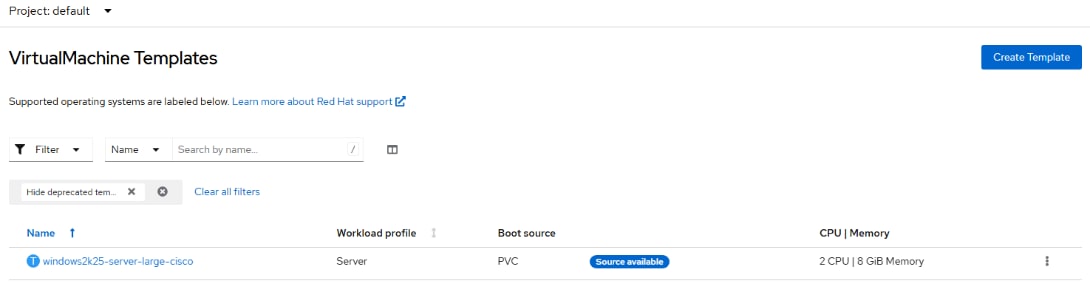
Step 37. Select Project: default. Select Virtualization > Templates. Select the windows2k25-server-large… template. Select the YAML tab and scroll down to line 232. Change the value field under DATA_SOURCE_NAME from win2k25 to windows2k25. Click Save and Reload.

Step 38. Select Virtualization > Templates. The template now displays the Source available.
Step 39. Click the template again and then select the Disks tab. If the Interface for the rootdisk is SATA, click the three dots to the right and select Edit. Change the Interface to VirtIO and click Save.
Step 40. To create a VM from this Template, select Virtualization > VirtualMachines under Project: default. Use the Create pulldown to select From template. Under Template project, select User templates. Select the newly created template with Source available. When using this template, the Disk source can be left at Template default without checking Boot from CD. The disk size specified must be greater than or equal to the disk size used to create the data source (64G) plus the 5% snapshot reserve (total 68G). Also, make sure to click the Network tab and Disk tab to ensure these are set properly.
Step 41. When the new VM is brought up, Disk Management will need to be used to extend the C: volume to the end of the disk. The new VM will also need to be assigned a new VM host name.
Procedure 6. Install the virtctl Command Line Utility
The virtctl client is a supplemental command-line utility for managing virtualization resources from the command line. For more information, see https://docs.openshift.com/container-platform/4.16/virt/getting_started/virt-using-the-cli-tools.html.
Step 1. Using Chrome from the OpenShift Installer VM, in the OpenShift Console, select Virtualization > Overview. If necessary, close the Welcome to OpenShift Virtualization popup. In the upper right corner of the, click Download the virtctl command-line utility. On the Command Line Tools page, click Download virtctl for Linux for x86_64.
Step 2. From a terminal window, type the following commands:
cd ~/Downloads
tar -xzvf virtctl.tar.gz
sudo cp virtctl /usr/local/bin/
rm virtctl*
Step 3. Use virtctl to restart a VM. Go to Virtualization > VirtualMachines in the default project to Monitor from the OpenShift Console.
oc project default
oc get vms
NAME AGE STATUS READY
rhel9-test-01 21h Running True
rhel9-test-02 21h Running True
win2k22-test-01 17h Running True
win2k22-test-02 17h Running True
virtctl restart rhel9-test-01
Procedure 7. VM Snapshots
Snapshots can be created at the VM level and at the VM disk level. With FlexPod, NetApp Trident applies these snapshots on the storage volumes where the VM disks are located. The VM can then be restored to the point in time that the snapshot was taken. Also, the default NetApp Trident backends and storage classes configured in the FlexPod Datacenter with Red Hat OpenShift Bare Metal Manual Configuration with Cisco UCS X-Series Direct CVD leave the Default snapshot policies on the VM disk volumes in storage. A VM could be shut down and NetApp tools used to restore a NetApp snapshot of the volume, restoring the disk to a point in time. For more information on VM snapshots, please visit Backup and restore by using VM snapshots - Backup and restore | Virtualization | OpenShift Container Platform 4.17.
Step 1. To create a VM snapshot in the OpenShift Console, select Virtualization > VirtualMachines. At the top, select the project where the VM is located and then select the VM.
Step 2. To take a VM snapshot, click Take snapshot. Give the snapshot a unique name and click Save.

Step 3. Select the Snapshots tab. The new snapshot now appears in the list. Click the ellipses to the right of the snapshot for snapshot options. Notice that Restore VirtualMachine from snapshot is greyed out since the VM would need to be stopped to restore the snapshot.
Note: It has been found that if a vTPM or persistent EFI is assigned to a VM, a snapshot of that VM will fail.
Procedure 8. Deploy the Migration Toolkit for Virtualization Operator
The Migration Toolkit for Virtualization Operator is used to migrate VMs from VMware and other sources into OpenShift Virtualization and to migrate VMs between OpenShift clusters.
Step 1. In the OpenShift Console, select Operators > OperatorHub. Type Migration in the search box and choose Migration Toolkit for Virtualization Operator provided by Red Hat. Click Install. Leave all settings at their defaults and click Install again.
Step 2. Once the Operator is installed, click Create ForkliftController. Click Create. Wait for the Status to become “Condition: Running.” Click to Refresh web console.
Step 3. On the left, select Migration > Overview. The Migration Toolkit for Virtualization has been successfully installed.
Procedure 9. Deploy OpenShift Image Registry
The OpenShift internal Image Registry will be used here to store the VMware VDDK container that accelerates converting and migrating VMware VMs to OpenShift Virtualization VMs. This registry can also be used to locally store any additional customized containers used by applications.
Step 1. The image registry was removed during the OpenShift on Bare Metal installation. Change the Image Registry Operator configuration’s managementState from Removed to Managed.
oc patch configs.imageregistry.operator.openshift.io cluster --type merge --patch '{"spec":{"managementState":"Managed"}}'
Step 2. Modify the registry configuration.
oc edit configs.imageregistry.operator.openshift.io
Step 3. Change the storage field to the format shown below (leaving the claim field blank) to automatically create a 100GB image-registry-storage PVC in the openshift-image-registry namespace and save the config with “:x” (vim save and exit).
storage:
pvc:
claim:
Step 4. Wait for the registry to become available.
oc get clusteroperator image-registry
NAME VERSION AVAILABLE PROGRESSING DEGRADED SINCE MESSAGE
image-registry 4.16.18 True False False 50s
Step 5. Ensure that your registry is set to managed to enable building and pushing of images.
oc describe configs.imageregistry/cluster | grep "Management State"
Management State: Managed
Management State: Managed
Management State: Managed
Step 6. To expose the registry using DefaultRoute:
oc patch configs.imageregistry.operator.openshift.io/cluster --patch '{"spec":{"defaultRoute":true}}' --type=merge
Procedure 10. Add VMware VDDK Container to Image Registry
Step 1. On your OpenShift installer VM, create and navigate to a temporary directory.
mkdir /tmp/vddk && cd /tmp/vddk
Step 2. Using Chrome, navigate to the VMware VDDK version 8 download page. Select Login and log into the site. Select version 8.0.1 for Linux (or the version that matches your vCenter) and click Download.
Note: A Broadcom VMware login will be needed to download the VDDK. Also, it is assumed you are migrating from vSphere 8.0 Update 1 or later.
Step 3. Move the downloaded file to the temporary directory.
mv ~/Downloads/VMware-vix-disklib-8.0.1-21562716.x86_64.tar.gz /tmp/vddk/
ls
VMware-vix-disklib-8.0.1-21562716.x86_64.tar.gz
Step 4. Extract the VDDK archive:
tar -xzvf VMware-vix-disklib-8.0.1-21562716.x86_64.tar.gz
Step 5. Create a Dockerfile:
cat > Dockerfile <<EOF
FROM registry.access.redhat.com/ubi8/ubi-minimal
USER 1001
COPY vmware-vix-disklib-distrib /vmware-vix-disklib-distrib
RUN mkdir -p /opt
ENTRYPOINT ["cp", "-r", "/vmware-vix-disklib-distrib", "/opt"]
EOF
Step 6. Get the exposed registry URL.
HOST=$(oc get route default-route -n openshift-image-registry --template='{{ .spec.host }}')
echo $HOST
default-route-openshift-image-registry.apps.ocp.flexpodb4.cisco.com
Step 7. Log into the registry with podman after logging into the cluster with a cluster-admin user.
oc login -u admin -p <password>
podman login -u admin -p $(oc whoami -t) --tls-verify=false $HOST
Step 8. Build and tag the VDDK image.
podman build . -t $HOST/openshift/vddk:8.0.1
Successfully tagged default-route-openshift-image-registry.apps.ocp.flexpodb4.cisco.com/openshift/vddk:8.0.1
Step 9. Push the image to the image registry.
podman push $HOST/openshift/vddk:8.0.1 --tls-verify=false
Getting image source signatures
Copying blob 12d5399f6d50 done |
Copying blob 325e71f5b538 done |
Copying blob 7e02eaad2ba1 done |
Copying config 120bbf6b2d done |
Writing manifest to image destination
Step 10. Restore the default oc login.
cp <path>/kubeconfig ~/.kube/config
Procedure 11. Add a VMware Migration Provider
Use the following steps to add a VMware Migration Provider to the Migration Providers for virtualization.
Step 1. In the OpenShift Console, select Migration > Providers for virtualization. Switch to the openshift-mtv project. Click Create Provider.
Step 2. Select vSphere. For Provider resource name, enter your vCenter hostname with all lowercase characters. Select the vCenter Endpoint type. For URL, enter https://<vcenter-fqdn>/sdk. For VDDK init image, the VDDK can be accessed internally in the cluster. Enter image-registry.openshift-image-registry.svc:5000/openshift/vddk:8.0.1. For Provider credentials, use administrator@vsphere.local and the corresponding password. Select to Skip certificate validation. Click Create provider.
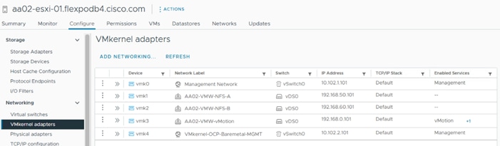
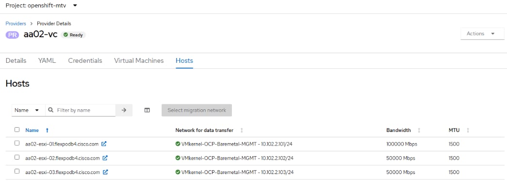
Step 3. For VM migrations, it is best to have a direct connection in the same subnet between the VMware cluster and the OpenShift cluster. It is recommended to pipe the VLAN used for OpenShift Bare Metal / Management into the VMware cluster and configure a port group with this VLAN on vSwitch0 on each ESXi host. Then create a VMkernel port with the Management service on each ESXi host in the OpenShift Bare Metal / Management subnet with no default gateway. It is important that the Network Label for the VMkernel port is the same on all ESXi hosts. The following screenshot shows this VMkernel port on one ESXi host.
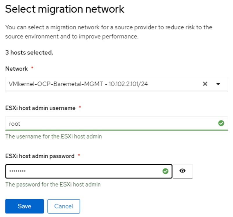
Step 4. In the OpenShift Console, select Migration > Providers for virtualization. Select the vCenter provider to bring up the Provider Details page. In the tab bar, select Hosts. Using the checkboxes, select each ESXi host and then click Select migration network. From the drop-down list select VMkernel portgroup created in the previous step. Enter root for the ESXi host admin username and the corresponding password. Click Save.
Step 5. Repeat this process for all ESXi hosts.
Procedure 12. Migrate VMware VMs to OpenShift Virtualization
Now that the Migration Toolkit for Virtualization Operator has been fully set up, VMware VMs can be migrated to any namespace within the OpenShift cluster.
Step 1. If a new namespace is required, create the namespace. Go to Project > Create Project in the OpenShift Console. If Network Attachment Definitions are needed within the namespace, create them within the namespace or Project.
Step 2. VM Migrations must occur within the openshift-mtv namespace. Select Project > openshift-mtv in the OpenShift Console. Then choose Migration > Plans for virtualization. In the upper right, click Create Plan.
Step 3. Select the vCenter as the source provider. Then, select any supported Windows or Linux VMs and click Next.
Step 4. Give the plan a name, such as migrate-<vm name>. Leave host as the Target provider. Select the appropriate Target namespace. Select the appropriate Target network under Network mappings and Target storage (Storage Class) under Storage mappings. Click Create migration plan.
Step 5. It will take a few minutes for the migration plan to get to a Status of Ready. Once the Status is Ready, click Start migration. Note that any running VMs will be shut down. Click Start.
Step 6. To monitor the status of the VM migration, click 0 of X VMs migrated. Then, next to any VM, click > to monitor the migration status. Depending on the VM disk number and size, the migration will take some time.
Step 7. Once the migration has Succeeded, select Virtualization > VirtualMachines, then select the project you migrated the VM(s) into. Select a VM that was migrated. If the VM is running, wait for any reboot cycles to complete and then Stop the VM. Select the Configuration tab and then select Network. The migration preserved the VMware MAC address. If you want to use an OpenShift MAC address, note the values of each field, then click the three dots to the right and choose Delete followed by Delete again. Then click Add network interface. Select or fill in the noted values and click Save. Now the VM should have an OpenShift MAC address.
Step 8. Select Actions > Start to power on the VM. Select the Console tab to interact with the VM. The VM networking will need to be set up for the VM in OpenShift if DHCP is not being used.
Procedure 13. Migrate an OpenShift VM to a Different Namespace and Backing Up VMs
The virtctl export command can be used to export a VM disk and VM configuration, and then the disk can be exported into a different namespace along with a modified VM configuration. This method can also be used to migrate VMs between OpenShift clusters and for VM Backup and Restore.
Step 1. A storage location will need to be set up, which is large enough to hold large numbers of VM disks. It is recommended to use the OpenShift Installer VM for this since it already contains configurations to access the OpenShift cluster. One way to set up a large storage location is to create a volume on the NetApp storage and mount it with NFS from this VM. You will need to have a network interface in the NFS VLAN to the VM and configure this interface with MTU 9000. Once the NFS mount is setup, create a directory for each VM and switch into this directory.
Step 2. For the VM to export, if you want to leave it running, in the OpenShift Console select Virtualization > VirtualMachines. Then select the VM to export. On the right, click Take snapshot. Name the snapshot snapshot-for-export and click Save.
Step 3. On the OpenShift Installer VM from the VM backup directory, export the VM disk and VM manifest. Depending on the disk size, this can take some time.
oc project <vm-namespace>
virtctl vmexport download <vm-name> --snapshot=snapshot-for-export --output=disk.img
virtctl vmexport download <vm-name> --snapshot=snapshot-for-export --manifest > <vm-name>.yaml
Note: If the VM has more than one disk, you will need to add “—volume=<pvc name>” to the disk export command along with a disk number in the –output field and run this command once for each disk.
Step 4. Delete the snapshot from the source VM.
Step 5. Import the VM disk(s) into the new namespace. The disk(s) will be uploaded using the default Storage Class and will create a PVC with the same name as the dv.
oc project <new-vm-namespace>
virtctl image-upload dv <vm-name> --image-path=./disk.img.gz --size=<source disk size>Gi –insecure
Note: If the VM has more than one disk, each disk will need to be uploaded to a unique PVC or DV.
Step 6. Using a text editor, edit the manifest .yaml file. Change the VM name if necessary and change the namespace to the new namespace name. Under interfaces, delete the macAddress line to set a new MAC address for this VM. If a different NAD is to be used with the new VM, change the networkName field. Next, change the persistentVolumeClaim > claimName to match the dv field in the command above. Finally, delete all the lines in the DataVolume section of the yaml file between the sets of “---” leaving only one “---” at the bottom of the file.
Step 7. Create the new VM in the new namespace.
oc create -f <vm-name>.yaml
Note: If you get an error message stating that the VM could not be created, run the command a second time and the VM should be successfully created.
Procedure 14. Attach a GPU to a VM
This procedure can be used to attach PCIe passthrough GPUs to VMs, which will pass an entire datacenter GPU in compute mode to a VM. Although it is possible to define vGPUs, which are subsets of full GPUs with a part of the GPU framebuffer, and pass through to VMs, that is not defined here. For defining and passing through vGPUs to VMs, see https://docs.openshift.com/container-platform/4.16/virt/virtual_machines/advanced_vm_management/virt-configuring-virtual-gpus.html.
Step 1. Node labeling can be used to designate worker node GPUs to be used for containerized applications or for VMs. To label a node to passthrough its GPUs to VMs, from the OpenShift Installer VM, run the following command:
oc label node <node_name> nvidia.com/gpu.deploy.operands=false
Step 2. Verify that the label was added to the node:
oc describe node <node_name>
Step 3. This will cause the NVIDIA GPU operator to unload the NVIDIA GPU driver pods from that node. This can be verified with the following commands. The NVIDIA GPU Operator pods should no longer be running on the labeled node.
oc get pods -n nvidia-gpu-operator -o wide
Step 4. Create a custom resource (CR) to enable either Intel Virtualization Technology for Directed I/O extensions (IOMMU) or AMD IOMMU on the worker nodes.
cat 100-worker-kernel-arg-iommu.yaml
apiVersion: machineconfiguration.openshift.io/v1
kind: MachineConfig
metadata:
labels:
machineconfiguration.openshift.io/role: worker
name: 100-worker-iommu
spec:
config:
ignition:
version: 3.2.0
kernelArguments:
- intel_iommu=on
Step 5. Create the new MachineConfig object:
oc create -f 100-worker-kernel-arg-iommu.yaml
Step 6. Verify that the new MachineConfig was created:
oc get MachineConfig
Step 7. Wait until the MachineConfig has been applied to all workers by monitoring MachineConfigPools. Ssh to the worker node with the passthrough GPU(s) and obtain the vendor-ID and the device-ID for the GPU device. In this case the vendor-ID is 10de and the device-ID is 26b9.
ssh core@<worker-baremetal-ip>
lspci -nnv | grep -i nvidia
38:00.0 3D controller [0302]: NVIDIA Corporation AD102GL [L40S] [10de:26b9] (rev a1)
Subsystem: NVIDIA Corporation Device [10de:1851]
d8:00.0 3D controller [0302]: NVIDIA Corporation AD102GL [L40S] [10de:26b9] (rev a1)
Subsystem: NVIDIA Corporation Device [10de:1851]
exit
Step 8. In your machine-configs directory, create 100-worker-vfiopci.bu to bind the GPU(s) to the VFIO driver and substituting your GPU’s vendor-ID and device-ID.
variant: openshift
version: 4.16.0
metadata:
name: 100-worker-vfiopci
labels:
machineconfiguration.openshift.io/role: worker
storage:
files:
- path: /etc/modprobe.d/vfio.conf
mode: 0644
overwrite: true
contents:
inline: |
options vfio-pci ids=10de:26b9
- path: /etc/modules-load.d/vfio-pci.conf
mode: 0644
overwrite: true
contents:
inline: vfio-pci
Step 9. Use butane to generate a MachineConfig yaml file.
./butane 100-worker-vfiopci.bu -o 100-worker-vfiopci.yaml
Step 10. Apply the MachineConfig to the worker nodes to attach any unattached GPUs to the VFIO driver.
oc apply -f 100-worker-vfiopci.yaml
Step 11. Verify that the MachineConfig object was added.
oc get MachineConfig
Step 12. Ssh back to the worker node and verify the GPU is bound to the VFIO driver.
ssh core@<worker-baremetal-ip>
lspci -nnk -d 10de:
38:00.0 3D controller [0302]: NVIDIA Corporation AD102GL [L40S] [10de:26b9] (rev a1)
Subsystem: NVIDIA Corporation Device [10de:1851]
Kernel driver in use: vfio-pci
Kernel modules: nouveau
d8:00.0 3D controller [0302]: NVIDIA Corporation AD102GL [L40S] [10de:26b9] (rev a1)
Subsystem: NVIDIA Corporation Device [10de:1851]
Kernel driver in use: vfio-pci
Kernel modules: nouveau
Step 13. Edit the hyperconverged custom resource.
oc edit hyperconverged kubevirt-hyperconverged -n openshift-cnv
Step 14. Add the NVIDIA GPU as a permitted host device.
spec:
permittedHostDevices:
pciHostDevices:
- pciDeviceSelector: "10DE:26B9"
resourceName: "nvidia.com/NVIDIA-L40S”
Step 15. Save the changes and exit the editor with “:x” (vim save and exit).
Step 16. To attach a GPU to a VM, in the OpenShift Console select Virtualization > VirtualMachines. Then select the appropriate project. Select the VM and then select the Configuration tab. Select GPU devices. Give the GPU a name then select an available GPU under Device name. You can use the Add GPU device link to add multiple GPUs to a VM. Click Save to complete adding the GPU to the VM.
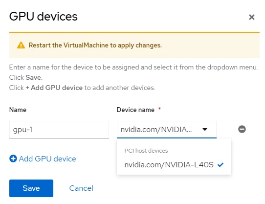
Step 17. You need to restart the VM to use the GPU. You will also need to install GPU guest drivers in the VM to use the GPU. In this validation, an NVIDIA L40S GPU was connected to a Windows 11 VM, NVIDIA GPU drivers installed, and the sdbds/InstantID-for-windows: InstantID : Zero-shot Identity-Preserving Generation in Seconds application was installed and run to test the GPU.
Data Protection for VMs in OpenShift Virtualization using NetApp Trident Protect
In this section, we demonstrate the installation and configuration of Trident protect. Then, we showcase how Trident protect can be used to perform snapshots and backup of VMs in OpenShift Virtualization, followed by restore operations.
Procedure 1. Install Trident protect on the OpenShift cluster
Step 1. From the OpenShift Installer VM, run the following command to add the Trident protect Helm repository.
helm repo add netapp-trident-protect https://netapp.github.io/trident-protect-helm-chart
Step 2. Create Trident protect namespace.
oc create namespace trident-protect
Step 3. Install Trident protect using Helm.
helm install trident-protect netapp-trident-protect/trident-protect --set clusterName=ocp-cluster --version 100.2506.0 -n trident-protect
Step 4. Check the pods output after installation.
oc get pods -n trident-protect
NAME READY STATUS RESTARTS AGE
autosupportbundle-3a38a30e-a6e1-402b-8027-03d392dc8e0f-5q56t 1/1 Running 0 15h
trident-protect-controller-manager-86bffb589b-tgj9f 2/2 Running 0 7d9h
Note: For detailed information about Trident protect, refer to the following link:
https://docs.netapp.com/us-en/trident/trident-protect/learn-about-trident-protect.html
Procedure 2. Install the Trident protect CLI plugin
Trident protect CLI plugin is an extension of the Trident tridentctl utility, to create and interact with Trident protect custom resources (CRs).
Step 1. Download the Trident protect CLI plugin.
curl -L -o tridentctl-protect https://github.com/NetApp/tridentctl-protect/releases/download/25.06.0/tridentctl-protect-linux-amd64
Step 2. Enable execute permissions for the plugin binary.
chmod +x tridentctl-protect
Step 3. Copy the plugin binary to a location that is defined in your PATH variable.
sudo cp ./tridentctl-protect /usr/local/bin/
Note: Copying the plugin to a location in your PATH variable enables you to use the plugin by typing tridentctl-protect or tridentctl protect from any location.
Step 4. Check the Trident protect installed version.
tridentctl-protect version
25.06.0
Step 5. Use the help function to view usage guidance.
tridentctl-protect help
Procedure 3. Configure Trident protect AppVault for ONTAP S3
Prior to creating the snapshots and backups for a VM, an Object Storage must be configured in Trident protect to store the snapshots and backups. This is done using the bucket CR (Custom Resource). The bucket CR is known as AppVault in Trident protect. AppVault objects are the declarative Kubernetes workflow representation of a storage bucket. An AppVault CR contains the configurations necessary for a bucket to be used in protection operations, such as backups, snapshots, restore operations, and SnapMirror replication. Only administrators can create AppVaults.
In this solution, we used ONTAP S3 as Object storage. Make sure you have configured ONTAP S3 object storage as described here: FlexPod Datacenter with Red Hat OCP Bare Metal Manual Configuration with Cisco UCS X-Series Direct Deployment Guide. Keep the access Key and Secret Key in a safe location.
Step 1. When defining an AppVault CR, we need to include credentials to access the resources hosted by the provider (here ONTAP S3). On the OpenShift Installer VM, create appvault-secret.yaml and update with access key and secret access key of ONTAP S3.
cat appvault-secret.yaml
---
apiVersion: v1
stringData:
accessKeyID: "<access key of S3>"
secretAccessKey: "<secret access key of S3>"
# you can also provide base 64 encoded values instead of string values
# data:
# base 64 encoded values
# accessKeyID: < base 64 encoded access key>
# secretAccessKey: <base 64 encoded secretAccess key>
kind: Secret
metadata:
name: appvault-secret
namespace: trident-protect
type: Opaque
Step 2. Create a secret to store the ONTAP S3 credentials.
oc create -f appvault-secret.yaml
Step 3. Create appvault.yaml and update with ONTAP S3 related info like bucket name, S3 LIF IP etc. Note that the AppVault CR needs to reside on the OpenShift cluster where Trident protect is installed.
cat appvault.yaml
---
apiVersion: protect.trident.netapp.io/v1
kind: AppVault
metadata:
name: ontap-s3-appvault
namespace: trident-protect
spec:
providerType: OntapS3
providerConfig:
s3:
bucketName: s3-bucket1
endpoint: <lif for S3 access>
secure: "false"
skipCertValidation: "true"
providerCredentials:
accessKeyID:
valueFromSecret:
key: accessKeyID
name: appvault-secret
secretAccessKey:
valueFromSecret:
key: secretAccessKey
name: appvault-secret
Step 4. Create an AppVault object for ONTAP S3.
oc create -f appvault.yaml
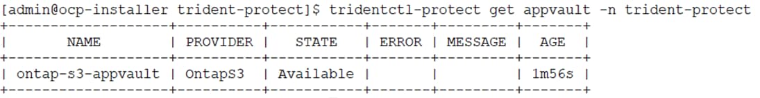
Step 5. View the newly created AppVault object. You can use the Trident protect CLI plugin to get information about AppVault objects that you have created on the cluster.
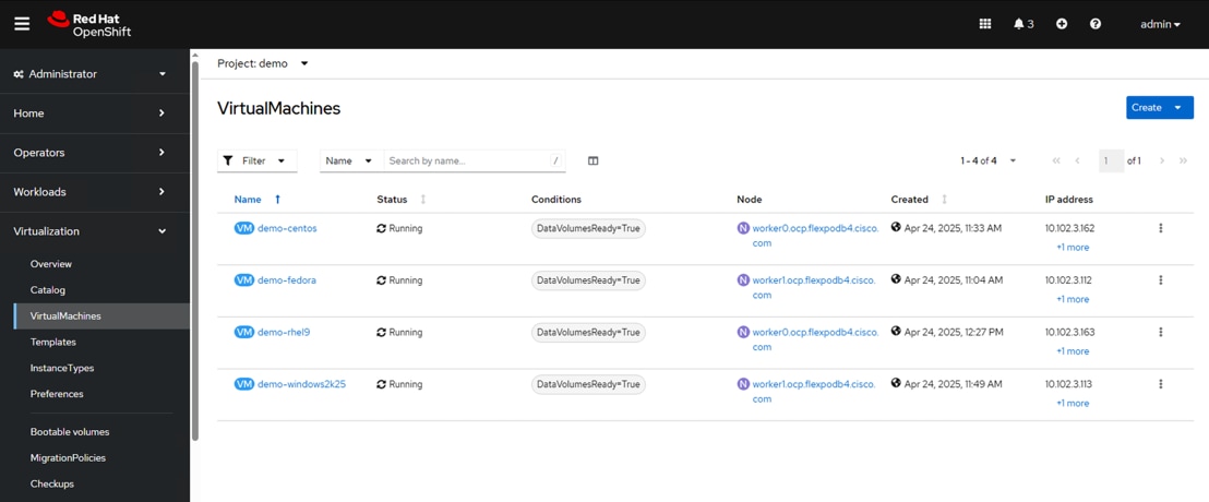
Procedure 4. Create VMs in OpenShift Virtualization
In this solution, we deployed four VMs, CentOS Stream 9, RHEL 9, Fedora, and Windows Server 2025 in demo namespace for validation purpose. You can choose to deploy any other VMs of your choice for solution validation. The root disk chooses the default storage class automatically, so, verify the default storage class is set appropriately. In this setup, the default storage class is ontap-nfs. Ensure that when you create the additional disk, you choose the storage class ontap-nfs and check the “Apply optimized storage settings” checkbox. This will set the Access modes to RWX and Volume Mode to Block. In this setup, VMs are created with a root disk and a data disk.
The following figure shows the VMs created in demo namespace:
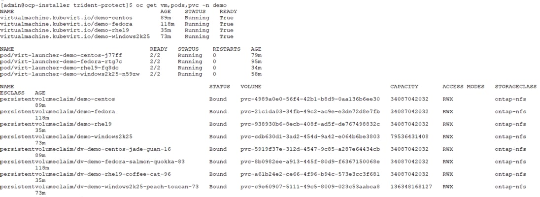
The following output shows the VMs, pods, and PVCs configured in demo namespace:
Procedure 5. Selecting specific VMs in a namespace to create snapshots/backup and restore
In this validation, we selected two VMs, RHEL 9 and Windows Server 2025 in demo namespace for which we will perform snapshots, backup, and restore in next procedures.
Step 1. Label the demo-rhel9, demo-windows2k25 VMs, and their associated resources in the demo namespace.
oc label vms demo-rhel9 demo-windows2k25 category=protect-rhel-win2k25-vms -n demo
oc label pvc demo-rhel9 demo-windows2k25 dv-demo-rhel9-coffee-cat-96 dv-demo-windows2k25-peach-toucan-73 category=protect-rhel-win2k25-vms -n demo
Step 2. Verify that the RHEL, Windows VMs, and corresponding PVCs got the labels.
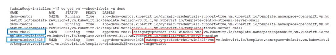
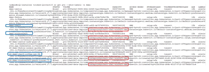
Procedure 6. Create an application for specific VMs using the label selector
You need to define an application to manage with Trident protect by creating an application CR. In this validation, we created an application for RHEL and Windows VMs using the label selector.
Step 1. Create demo-vms-app.yaml to define an application for demo-rhel9, demo-windows2k25 VMs using label selector.
cat demo-vms-app.yaml
---
apiVersion: protect.trident.netapp.io/v1
kind: Application
metadata:
creationTimestamp: null
name: demo-vms-app
namespace: demo
spec:
includedNamespaces:
- labelSelector:
matchLabels:
category: protect-rhel-win2k25-vms
namespace: demo
status:
conditions: null
Step 2. Create Application using the above application CR file.
oc create -f demo-vms-app.yaml
Step 3. Verify the newly created application in the demo namespace.
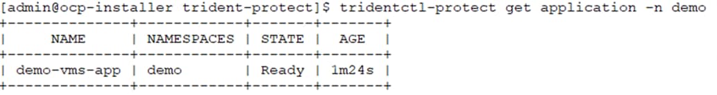
Procedure 7. Create on-demand backup of specific VMs in a namespace by using corresponding application
In the previous step, an application was created using label selectors to include only the demo-rhel9 and demo-windows2k25 VMs in the demo namespace. Now, here we will create an on-demand backup for this application.
Step 1. Run the following command to create an on-demand backup for the application (demo-vms-app). Provide the ONTAP S3 AppVault name where the backup will be stored.
tridentctl-protect create backup demo-vms-backup-on-demand --app demo-vms-app --appvault ontap-s3-appvault -n demo
Step 2. Verify that the backup (demo-vms-backup-on-demand) was created successfully.
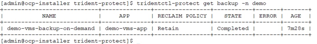
Step 3. You can also check that the backup is stored in ONTAP S3 bucket through some applications like S3 Browser as shown below:
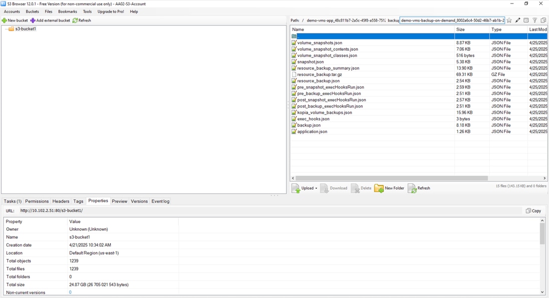
Procedure 8. Restore specific VMs to a different namespace
Restoring a VM to a different namespace allows us to move an application (and its associated resources) from one project to another, such as from a development namespace to a production namespace. We can easily create copies of a VM for testing or development purposes without impacting the production environment. One can create a replica or clone of the VM in a separate namespace for disaster recovery purposes. In this validation, we will use the on-demand backup created in previous step to restore the demo-rhel9 and demo-windows2k25 VMs to a different namespace.
Step 1. Create a new namespace to which you want to restore the application. In this validation, demo2 namespace was created as below.
oc create namespace demo2
Step 2. Create a backup restore object to a different namespace (demo2) from the on-demand backup (demo-vms-backup-on-demand).
tridentctl-protect create backuprestore <backup_restore_name> --backup <backup_namespace>/<backup_to_restore> --namespace-mapping <source_to_destination_namespace_mapping> -n <application_namespace>
tridentctl-protect create backuprestore demo2-vms-restore --backup demo/demo-vms-backup-on-demand --namespace-mapping demo:demo2 -n demo2
Step 3. Verify that the backup restore object demo2-vms-restore was created successfully.
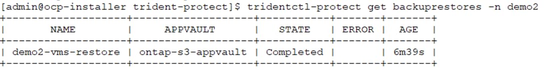
Step 4. Verify that the RHEL and Windows VMs have been recreated in demo2 namespace. As shown in the following figures, VMs and PVCs are restored successfully.
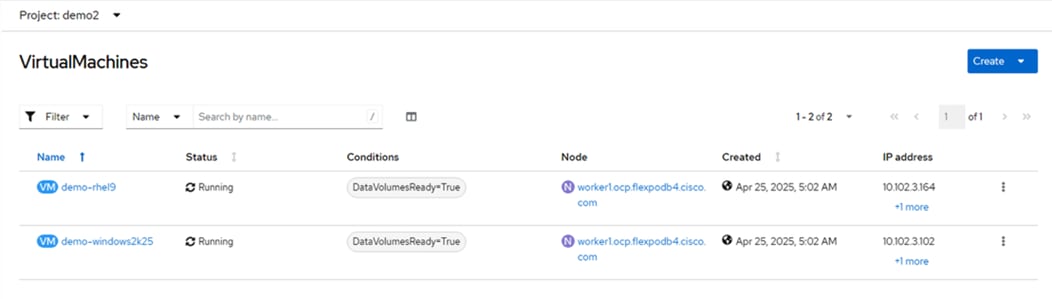
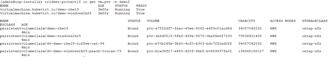
Procedure 9. Create a schedule for snapshots
A protection policy protects an application by creating snapshots, backups, or both at a defined schedule. You can choose to create snapshots and backups hourly, daily, weekly, and monthly, and can specify the number of copies to retain. In this validation, we will create schedule-based snapshots for the application demo-vms-app.
Step 1. Create the custom resource (CR) file snapshot-schedule-demo-vms.yaml to configure schedule for the snapshots. Specify the granularity and the number of snapshots to be retained.
cat snapshot-schedule-demo-vms.yaml
---
apiVersion: protect.trident.netapp.io/v1
kind: Schedule
metadata:
creationTimestamp: null
name: snapshot-schedule1
namespace: demo
spec:
appVaultRef: ontap-s3-appvault
applicationRef: demo-vms-app
backupRetention: "0"
dayOfMonth: ""
dayOfWeek: ""
enabled: true
granularity: Hourly
hour: ""
minute: "50"
recurrenceRule: ""
snapshotRetention: "2"
status: {}
Step 2. Create snapshots in demo namespace using below command:
oc create -f snapshot-schedule-demo-vms.yaml
Note: You can also create the schedule using the CLI method as illustrated below:
tridentctl-protect create schedule <schedule_name> --app <name_of_app_to_snapshot> --appvault <appvault_name> --granularity <frequency_to_run> --minute <minute_of_hour_to_run> --snapshot-retention <how_many_snapshots_to_retain> -n <application_namespace>
tridentctl-protect create schedule snapshot-schedule1 --app demo-vms-app --appvault ontap-s3-appvault --granularity Hourly --minute 50 --snapshot-retention 2 -n demo
Step 3. Verify the newly created schedule snapshot-schedule1 is in place as shown below.
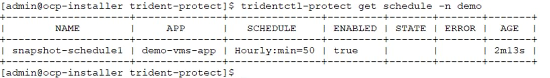
Step 4. View the snapshots created for the demo-vms-app application. Based on the schedule, two snapshot copies would be retained as shown below:
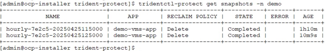
Step 5. You can also verify that the snapshots are stored successfully in ONTAP S3 bucket using some applications like S3 browser as shown below:
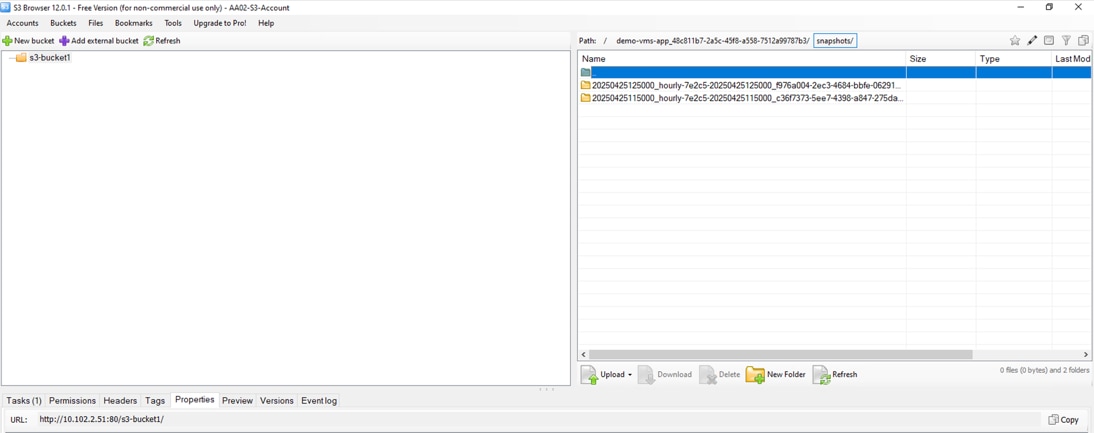
Procedure 10. Restore the VMs from the snapshot to the same namespace
In the event of any disaster, if a VM is compromised or gets corrupted, you can use the backup or snapshot to restore the VM to the original namespace. In this validation, we will use one of the snapshots created in previous step to restore the demo-rhel9 and demo-windows2k25 VMs to the demo namespace.
Step 1. Simulate disaster by deleting the specific VMs (demo-rhel9 and demo-windows2k25) from the demo namespace.
oc delete vms demo-rhel9 demo-windows2k25 -n demo
Step 2. Verify that the RHEL, Windows VMs, and their associated resources are deleted from the demo namespace.
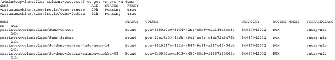
Step 3. Create the CR file vm-demo-snapshotinplacerestore.yaml to configure snapshot-in-place-restore object from the snapshot of the VMs.
cat vm-demo-snapshotinplacerestore.yaml
---
apiVersion: protect.trident.netapp.io/v1
kind: SnapshotInplaceRestore
metadata:
creationTimestamp: null
name: demo-vms-restore-from-snapshot
namespace: demo
spec:
appArchivePath: demo-vms-app_48c811b7-2a5c-45f8-a558-7512a99787b3/snapshots/20250425115000_hourly-7e2c5-20250425115000_c36f7373-5ee7-4398-a847-275da06510e1
appVaultRef: ontap-s3-appvault
resourceFilter: {}
status:
conditions: null
postRestoreExecHooksRunResults: null
state: ""
Note: You can execute the below command to find the value for “appArchivePath” field in the above YAML manifest.
oc describe snapshot <name of snapshot> -n <namespace> | grep “App Archive Path”
oc describe snapshot hourly-7e2c5-20250425115000 -n demo | grep "App Archive Path"
App Archive Path: demo-vms-app_48c811b7-2a5c-45f8-a558-7512a99787b3/snapshots/20250425115000_hourly-7e2c5-20250425115000_c36f7373-5ee7-4398-a847-275da06510e1
Step 4. Create the snapshot-in-place-restore object in demo namespace using the following command.
oc create -f vm-demo-snapshotinplacerestore.yaml
Note: You can also create the snapshot-in-place-restore object using the CLI method as shown below:
tridentctl-protect create snapshotinplacerestore <restore_name> --snapshot <snapshot_to_restore> -n <application_namespace>
tridentctl-protect create snapshotinplacerestore demo-vms-restore-from-snapshot --snapshot demo/hourly-7e2c5-20250425115000 -n demo
Step 5. Verify the newly created snapshot-in-place-restore object (demo-vms-restore-from-snapshot) as shown below:
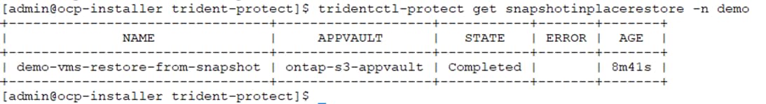
Step 6. Verify that the RHEL and Windows VMs (demo-rhel9 and demo-windows2k25), and their corresponding PVCs are restored to the demo namespace as shown in the following figures:
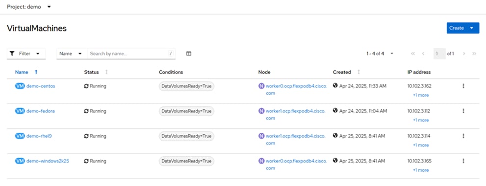
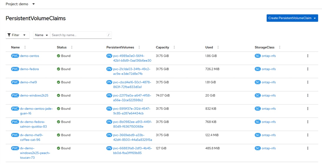
John George, Technical Marketing Engineer, Cisco Systems, Inc.
John has been involved in designing, developing, validating, and supporting the FlexPod Converged Infrastructure since it was developed more than 13 years ago. Before his role with FlexPod, he supported and administered a large worldwide training network and VPN infrastructure. John holds a master’s degree in Computer Engineering from Clemson University.
Kamini Singh, Technical Marketing Engineer, Hybrid Cloud Infra & OEM Solutions, NetApp
Kamini Singh is a Technical Marketing engineer at NetApp. She has more than five years of experience in data center infrastructure solutions. Kamini focuses on FlexPod hybrid cloud infrastructure solution design, implementation, validation, automation, and sales enablement. Kamini holds a bachelor’s degree in Electronics and Communication and a master’s degree in Communication Systems.
Acknowledgements
For their support and contribution to the design, validation, and creation of this Cisco Validated Design, the authors would like to thank:
● Archana Sharma, Technical Marketing Engineer, Cisco Systems, Inc.
● Paniraja Koppa, Technical Marketing Engineer, Cisco Systems, Inc.
For comments and suggestions about this guide and related guides, join the discussion on Cisco Community at https://cs.co/en-cvds.
CVD Program
ALL DESIGNS, SPECIFICATIONS, STATEMENTS, INFORMATION, AND RECOMMENDATIONS (COLLECTIVELY, "DESIGNS") IN THIS MANUAL ARE PRESENTED "AS IS," WITH ALL FAULTS. CISCO AND ITS SUPPLIERS DISCLAIM ALL WARRANTIES, INCLUDING, WITHOUT LIMITATION, THE WARRANTY OF MERCHANTABILITY, FITNESS FOR A PARTICULAR PURPOSE AND NONINFRINGEMENT OR ARISING FROM A COURSE OF DEALING, USAGE, OR TRADE PRACTICE. IN NO EVENT SHALL CISCO OR ITS SUPPLIERS BE LIABLE FOR ANY INDIRECT, SPECIAL, CONSEQUENTIAL, OR INCIDENTAL DAMAGES, INCLUDING, WITHOUT LIMITATION, LOST PROFITS OR LOSS OR DAMAGE TO DATA ARISING OUT OF THE USE OR INABILITY TO USE THE DESIGNS, EVEN IF CISCO OR ITS SUPPLIERS HAVE BEEN ADVISED OF THE POSSIBILITY OF SUCH DAMAGES.
THE DESIGNS ARE SUBJECT TO CHANGE WITHOUT NOTICE. USERS ARE SOLELY RESPONSIBLE FOR THEIR APPLICATION OF THE DESIGNS. THE DESIGNS DO NOT CONSTITUTE THE TECHNICAL OR OTHER PROFESSIONAL ADVICE OF CISCO, ITS SUPPLIERS OR PARTNERS. USERS SHOULD CONSULT THEIR OWN TECHNICAL ADVISORS BEFORE IMPLEMENTING THE DESIGNS. RESULTS MAY VARY DEPENDING ON FACTORS NOT TESTED BY CISCO.
CCDE, CCENT, Cisco Eos, Cisco Lumin, Cisco Nexus, Cisco StadiumVision, Cisco TelePresence, Cisco WebEx, the Cisco logo, DCE, and Welcome to the Human Network are trademarks; Changing the Way We Work, Live, Play, and Learn and Cisco Store are service marks; and Access Registrar, Aironet, AsyncOS, Bringing the Meeting To You, Catalyst, CCDA, CCDP, CCIE, CCIP, CCNA, CCNP, CCSP, CCVP, Cisco, the Cisco Certified Internetwork Expert logo, Cisco IOS, Cisco Press, Cisco Systems, Cisco Systems Capital, the Cisco Systems logo, Cisco Unified Computing System (Cisco UCS), Cisco UCS B-Series Blade Servers, Cisco UCS C-Series Rack Servers, Cisco UCS S-Series Storage Servers, Cisco UCS Manager, Cisco UCS X-Series, Cisco UCS Management Software, Cisco Unified Fabric, Cisco Application Centric Infrastructure, Cisco Nexus 9000 Series, Cisco Nexus 7000 Series. Cisco Prime Data Center Network Manager, Cisco NX-OS Software, Cisco MDS Series, Cisco Unity, Collaboration Without Limitation, EtherFast, EtherSwitch, Event Center, Fast Step, Follow Me Browsing, FormShare, GigaDrive, HomeLink, Internet Quotient, IOS, iPhone, iQuick Study, LightStream, Linksys, MediaTone, MeetingPlace, MeetingPlace Chime Sound, MGX, Networkers, Networking Academy, Network Registrar, PCNow, PIX, PowerPanels, ProConnect, ScriptShare, SenderBase, SMARTnet, Spectrum Expert, SE1tackWise, The Fastest Way to Increase Your Internet Quotient, TransPath, WebEx, and the WebEx logo are registered trade-marks of Cisco Systems, Inc. and/or its affiliates in the United States and certain other countries. (LDW_UP1)
All other trademarks mentioned in this document or website are the property of their respective owners. The use of the word partner does not imply a partnership relationship between Cisco and any other company. (0809R)