FlexPod Datacenter Base Manual Configuration with Cisco IMM and NetApp ONTAP Deployment Guide
Available Languages
Bias-Free Language
The documentation set for this product strives to use bias-free language. For the purposes of this documentation set, bias-free is defined as language that does not imply discrimination based on age, disability, gender, racial identity, ethnic identity, sexual orientation, socioeconomic status, and intersectionality. Exceptions may be present in the documentation due to language that is hardcoded in the user interfaces of the product software, language used based on RFP documentation, or language that is used by a referenced third-party product. Learn more about how Cisco is using Inclusive Language.
- US/Canada 800-553-2447
- Worldwide Support Phone Numbers
- All Tools
 Feedback
 Feedback
![]()
In partnership with:

About the Cisco Validated Design Program
The Cisco Validated Design (CVD) program consists of systems and solutions designed, tested, and documented to facilitate faster, more reliable, and more predictable customer deployments. For more information, go to: http://www.cisco.com/go/designzone.
The FlexPod Datacenter solution is a validated design for deploying Cisco and NetApp technologies and products to build shared private and public cloud infrastructure. Cisco and NetApp have partnered to deliver a series of FlexPod solutions that enable strategic data center platforms. The success of the FlexPod solution is driven through its ability to evolve and incorporate both technology and product innovations in the areas of management, compute, storage, and networking. This document explains the deployment details of the base configuration of FlexPod Datacenter, setting up a configuration where bare metal OS or hypervisors can be layered on as tenants to support applications. Some of the key advantages of FlexPod Datacenter Base Configuration are:
● Consistent FlexPod Base Configuration: having a FlexPod Datacenter Base Configuration provides a consistent configuration that one or more of any bare metal OS or hypervisor can be layered on in a secure way to support one or more applications.
● Simpler and programmable infrastructure: the entire configuration can be configured using infrastructure as code delivered using Ansible.
● End-to-End 100Gbps Ethernet: utilizing the 5th Generation Cisco UCS VICs, the 6th Generation Cisco UCS 6664 Fabric Interconnect, and the Cisco UCSX-I-9108-100G Intelligent Fabric Module to deliver 100Gbps Ethernet from the server through the network to the storage.
● End-to-End 64Gbps Fibre Channel: utilizing the 5th Generation Cisco UCS VICs, the 6th Generation Cisco UCS 6664 Fabric Interconnect, and the Cisco UCSX-I-9108-100G Intelligent Fabric Module to deliver 64Gbps Fibre Channel from the server (via 100Gbps FCoE) through the network to the storage.
● Built for investment protections: design ready for future technologies such as liquid cooling and high-Wattage CPUs, CXL-ready.
In addition to the FlexPod-specific hardware and software innovations, the integration of the Cisco Intersight cloud platform with NetApp Active IQ Unified Manager, and Cisco Nexus and MDS switches delivers monitoring, orchestration, and workload optimization capabilities for different layers (storage and networking) of the FlexPod infrastructure. Implementation of this integration at this point in the deployment process would require Cisco Intersight Assist and NetApp Active IQ Unified Manager to be deployed outside of the FlexPod.
For information about the FlexPod design and deployment details, including the configuration of various elements of design and associated best practices, refer to Cisco Validated Designs for FlexPod, here: https://www.cisco.com/c/en/us/solutions/design-zone/data-center-design-guides/flexpod-design-guides.html.
Solution Overview
This chapter contains the following:
● Audience
The intended audience of this document includes but is not limited to IT architects, sales engineers, field consultants, professional services, IT managers, partner engineering, and customers who want to take advantage of an infrastructure built to deliver IT efficiency and enable IT innovation.
This document provides deployment guidance around bringing up the base FlexPod Datacenter infrastructure. The base configuration involves basic configuration that connects the FlexPod devices to the network, then configuring the base network configuration of each component, preparing the FlexPod for layering on bare metal OS, hypervisors, and applications in a multi-tenant way. This document introduces various design elements and explains various considerations and best practices for a successful deployment.
The following design elements distinguish this version of FlexPod from previous models:
● Configuration of only the base FlexPod, which mainly involves connecting the FlexPod devices to the network, then configuring the base network configuration of each component.
● All future FlexPod solution documents will refer to this document for a consistent base setup and then layer on the solution bare metal OS, hypervisor, and/or applications in a multi-tenant fashion.
Deployment Hardware and Software
This chapter contains the following:
The FlexPod Datacenter with Cisco UCS and Cisco Intersight meets the following general design requirements:
● Resilient design across all layers of the infrastructure with no single point of failure
● Scalable design with the flexibility to add compute capacity, storage, or network bandwidth as needed
● Modular design that can be replicated to expand and grow as the needs of the business grow
● Flexible design that can support different models of various components with ease
● Simplified design with ability to integrate and automate with external automation tools
● Cloud-enabled design which can be configured, managed, and orchestrated from the cloud using GUI or APIs
To deliver a solution which meets these design requirements, various solution components are connected and configured as explained in the upcoming sections.
The FlexPod Datacenter base configuration is built using the following hardware components:
● Cisco UCS X9508 Chassis with Cisco UCSX-I-9108-100G intelligent fabric modules (IFMs) and up to eight Cisco UCS X210c or X215c Compute Nodes. This chassis will also accommodate GPU nodes and UCS X-Fabric Technology
● Sixth-generation Cisco UCS 6664 Fabric Interconnects to support 100GbE, 25GbE, and 64GFC connectivity from various components
● Cisco UCS C-Series M8 rack mount servers
● High-speed Cisco NX-OS-based Nexus 9324C-SE1U Silicon One based smart switching design to support 100GE connectivity
● NetApp AFF A90 end-to-end NVMe storage with 25G or 100G Ethernet and (optional) 64G Fibre Channel connectivity
● Cisco MDS 9124V* switches to support Fibre Channel storage configuration
Note: * Cisco MDS 9124V and FC connectivity is not needed when implementing IP-based connectivity design supporting iSCSI boot from SAN, NFS, and NVMe-TCP.
The software components of this solution consist of:
● Cisco Intersight to deploy, maintain, and support the Cisco UCS server components
● Cisco Intersight SaaS platform to maintain and support the FlexPod components
● Cisco Nexus Dashboard LAN to configure a Classic LAN Fabric and monitor the Nexus switches
● Cisco Intersight Assist Virtual Appliance to help connect NetApp ONTAP and Cisco Nexus and MDS switches with Cisco Intersight
● NetApp Active IQ Unified Manager to monitor and manage the storage and for NetApp ONTAP integration with Cisco Intersight
FlexPod Datacenter for IP-based Storage Access
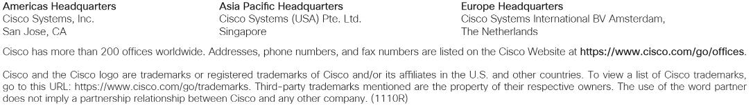
Figure 1 shows various hardware components and the network connections for the IP-based FlexPod design.
The reference hardware configuration includes:
● Two Cisco Nexus 9324C-SE1U Switches in Cisco NX-OS mode configured using a Nexus Dashboard Classic LAN fabric. Other Cisco Nexus Switches are also supported.
● Two Cisco UCS 6664 Fabric Interconnects (FI) provide chassis connectivity. Two 100 Gigabit Ethernet ports from each FI, configured as a Port-Channel, are connected to each Nexus 9324C-SE1U. 25 Gigabit Ethernet connectivity is also supported as well as earlier versions of the Cisco UCS FI, including the UCS 9108 FI.
● One Cisco UCS X9508 Chassis connects to fabric interconnects using Cisco UCS UCSX-I-9108-100G IFMs, where four 100 Gigabit Ethernet ports are used on each IOM to connect to the appropriate FI. If additional bandwidth is required, all eight 100G ports can be utilized. The Cisco UCS UCSX-I-9108-25G IFM is also supported with 25 Gigabit Ethernet Connectivity.
● One NetApp AFF A90 HA pair connects to the Cisco Nexus 9324C-SE1U Switches using two 100 GE ports from each controller configured as a Port-Channel. 25 Gigabit Ethernet connectivity is also supported as well as other NetApp AFF, ASA, and FAS storage controllers.
● One Cisco UCS C240 M8 rack mount server connects to the Fabric Interconnects using two 100 GE ports per server. Other Cisco UCS C-Series rack mount servers with both 25 GE and 100GE ports are also supported.
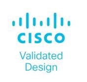
FlexPod Datacenter for FC-based Storage Access
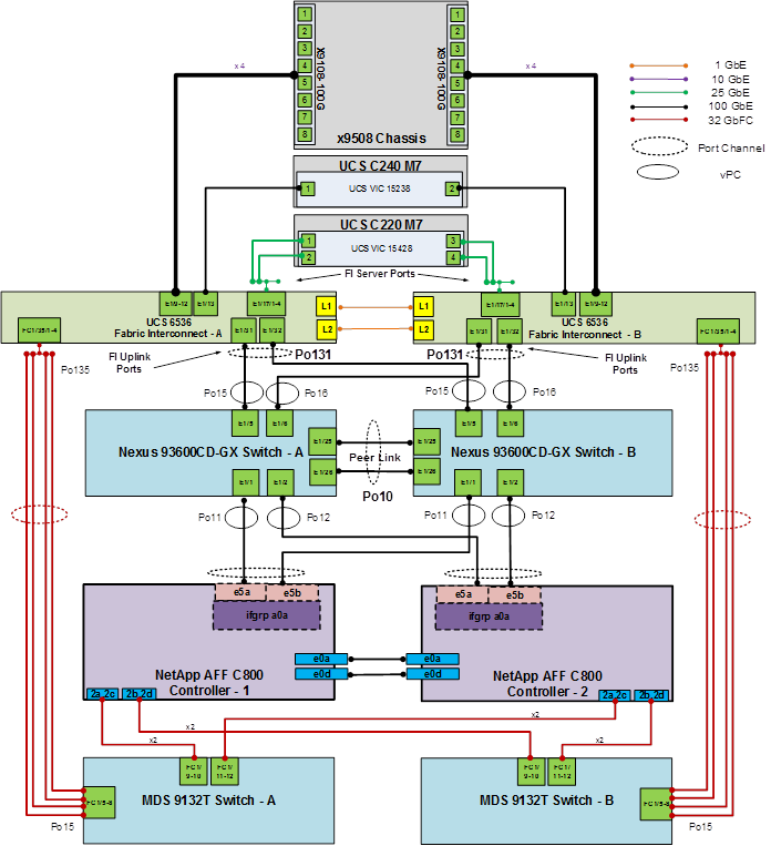
Figure 2 shows various hardware components and the network connections for the FC-based FlexPod design.
The reference hardware configuration includes:
● Two Cisco Nexus 9324C-SE1U Switches in Cisco NX-OS mode configured using a Nexus Dashboard Classic LAN fabric. Other Cisco Nexus Switches are also supported.
● Two Cisco UCS 6664 Fabric Interconnects (FI) provide the chassis connectivity. Two 100 Gigabit Ethernet ports from each FI, configured as a Port-Channel, are connected to each Nexus 9324C-SE1U. 25 Gigabit Ethernet connectivity is also supported. Two FC ports are connected to the Cisco MDS 9124V switches using 64-Gbps Fibre Channel connections via breakout configured as a single port channel for SAN connectivity. 32-Gbps and 16-Gbps Fibre Chanel connectivity is also supported as well as earlier versions of the Cisco UCS FI, including the UCS 9108 FI.
● One Cisco UCS X9508 Chassis connects to fabric interconnects using Cisco UCS UCSX-I-9108-100G IFMs, where four 100 Gigabit Ethernet ports are used on each IOM to connect to the appropriate FI. If additional bandwidth is required, all eight 100G ports can be utilized. The chassis to fabric interconnect connections are converged and carry both Ethernet and Fibre Channel over Ethernet (FCoE). The Cisco UCS UCSX-I-9108-25G IFM is also supported with 25 Gigabit Ethernet and FCoE Connectivity.
● One NetApp AFF A90 HA pair connects to the Cisco Nexus 9324C-SE1U Switches using two 100 GE ports from each controller configured as a Port-Channel. Two 64Gbps FC ports from each controller are connected to each Cisco MDS 9124V for SAN connectivity. 25 Gigabit Ethernet and 32 or 16-Gbps Fibre Channel connectivity is also supported as well as other NetApp AFF, ASA, and FAS storage controllers.
● One Cisco UCS C240 M8 Rack Mount Server connects to the Fabric Interconnects using two 100 GE ports per server. These connections are also converged and carry both Ethernet and FCoE. Other Cisco UCS C-Series rack mount servers with both 25 GE and 100GE ports are also supported.
Note: The NetApp storage controller and disk shelves should be connected according to best practices for the specific storage controller and disk shelves. For disk shelf cabling, go to NetApp Support: https://docs.netapp.com/us-en/ontap-systems/index.html
FlexPod Datacenter for FC-based Storage Access with Nexus SAN Switching
Figure 3 shows various hardware components and the network connections for the FC-based FlexPod design.

The reference hardware configuration includes:
● Two Cisco Nexus 93180YC-FX, 93360YC-FX2, or 9336C-FX2-E Switches in Cisco NX-OS mode provide the switching fabric for both LAN and SAN.
● Two Cisco UCS 6536 Fabric Interconnects (FI) provide the chassis connectivity. Two 100 Gigabit Ethernet ports from each FI, configured as a Port-Channel, are connected to each Nexus switch. Two 100G FCoE ports are connected to the Cisco Nexus switches configured as a single Ethernet port channel for SAN connectivity. 25 Gigabit Ethernet connectivity is also supported as well as earlier versions of the Cisco UCS FI.
● One Cisco UCS X9508 Chassis connects to fabric interconnects using Cisco UCS UCSX-I-9108-100G IFMs, where four 100 Gigabit Ethernet ports are used on each IOM to connect to the appropriate FI. If additional bandwidth is required, all eight 100G ports can be utilized. The chassis to fabric interconnect connections are converged and carry both Ethernet and Fibre Channel over Ethernet (FCoE). The Cisco UCS UCSX-I-9108-25G IFM is also supported with 25 Gigabit Ethernet and FCoE Connectivity.
● One NetApp AFF A90 HA pair connects to the Cisco Nexus Switches using two 100 GE ports from each controller configured as a Port-Channel. Two 64Gbps FC ports from each controller are connected to each Cisco Nexus switch for SAN connectivity (Cisco Nexus 9336C-FX2-E using breakout). 25 Gigabit Ethernet and 16-Gbps Fibre Channel connectivity is also supported as well as other NetApp AFF, ASA, and FAS storage controllers.
● One Cisco UCS C220 M7 Rack Mount Server connects to the Fabric Interconnects using two 100 GE ports per server. These connections are also converged and carry both Ethernet and FCoE.
● One Cisco UCS C220 M7 Rack Mount Server connects four 25 GE ports per server to the Fabric Interconnects. These connections are also converged and carry both Ethernet and FCoE.
Note: The NetApp storage controller and disk shelves should be connected according to best practices for the specific storage controller and disk shelves. For disk shelf cabling, refer to NetApp Support: https://docs.netapp.com/us-en/ontap-systems/index.html.
Note: Nexus SAN switching configuration is being left in this document in the Appendix, but is not updated and tested with the latest hardware.
VLAN Configuration
Table 1 lists VLANs configured for setting up the FlexPod environment along with their usage.
| VLAN ID |
Name |
Usage |
IP Subnet used in this deployment |
| 2 |
Native-VLAN |
Use VLAN 2 as native VLAN instead of default VLAN (1). |
|
| 1020 |
OOB-MGMT-VLAN |
Out-of-band management VLAN to connect management ports for various devices |
10.102.0.0/24; GW: 10.102.0.254 |
Some of the key highlights of VLAN usage are as follows:
● VLAN 1020 allows you to manage and access out-of-band management interfaces of various devices.
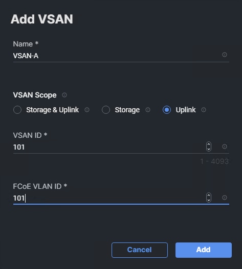
| VSAN ID |
FCoE VLAN ID |
Name |
Usage |
| 101 |
101 |
VSAN-A |
FlexPod Fabric A |
| 102 |
102 |
VSAN-B |
FlexPod Fabric B |
Table 3 lists the VMs or bare metal servers necessary for deployment as outlined in this document.
| Virtual Machine Description |
VLAN |
IP Address |
Comments |
| FlexPod AD1 |
1021 |
10.102.1.151 |
Hosted on pre-existing management infrastructure |
| FlexPod AD2 |
1021 |
10.102.1.152 |
Hosted on pre-existing management infrastructure |
| NetApp Active IQ Unified Manager |
1021 |
10.102.1.97 |
Hosted on pre-existing management infrastructure |
| Cisco Intersight Assist |
1021 |
10.102.1.96 |
Hosted on pre-existing management infrastructure |
| Nexus Dashboard -LAN |
1021 and 1020 |
10.102.1.24-26 |
Hosted on 3 VMs on pre-existing management infrastructure |
| Nexus Dashboard -SAN |
1021 and 1020 |
10.102.1.21 |
Hosted on a VM on pre-existing management infrastructure |
Table 4 lists the software revisions for various components of the solution.
| Layer |
Device |
Image Bundle |
Comments |
| Compute |
Cisco UCS Fabric Interconnect 6664 |
6.0(2.260045) |
|
| Cisco UCS X9108-100G IFM |
6.0(2b) |
|
|
| Cisco UCS X210C M8 |
6.0(2.260040) |
|
|
| Cisco UCS C220/240 M8 |
6.0(2.260044) |
|
|
| Network |
Cisco Nexus 9324C-SE1U NX-OS |
10.6(2)F |
|
| Cisco MDS 9124V |
9.4(3b) |
Requires SMART Licensing |
|
| Cisco Nexus Dashboard LAN |
4.2.1 |
|
|
| Cisco Nexus Dashboard SAN |
4.2.1 |
|
|
| Storage |
NetApp AFF A90 |
ONTAP 9.18.1 |
Latest patch release |
| Software |
Cisco Intersight Assist Appliance |
1.1.5-1 |
|
| NetApp Active IQ Unified Manager |
9.18 |
|
The information in this section is provided as a reference for cabling the physical equipment in a FlexPod environment. To simplify cabling requirements, a cabling diagram was used.
The cabling diagram in this section contains the details for the prescribed and supported configuration of the NetApp AFF A90 running NetApp ONTAP 9.18.1.
Note: For any modifications of this prescribed architecture, consult the NetApp Interoperability Matrix Tool (IMT).
Note: This document assumes that out-of-band management ports are plugged into an existing management infrastructure at the deployment site. These interfaces will be used in various configuration steps.
Note: Be sure to use the cabling directions in this section as a guide.
The NetApp storage controller and disk shelves should be connected according to best practices for the specific storage controller and disk shelves. For disk shelf cabling, refer to NetApp Support.
Figure 4 details the cable connections used in the validation lab for the FlexPod topology based on the Cisco UCS 6664 fabric interconnect. Two 64Gb uplinks connect as port-channels from each Cisco UCS Fabric Interconnect to the MDS switches, and a total of four 64Gb links connect the MDS switches to the NetApp AFF controllers. Also, two 100Gb links connect each Cisco UCS Fabric Interconnect to the Cisco Nexus Switches and each NetApp AFF controller to the Cisco Nexus Switches. Additional 1Gb management connections will be needed for an out-of-band network switch that sits apart from the FlexPod infrastructure. Each Cisco UCS fabric interconnect and Cisco Nexus switch is connected to the out-of-band network switch, and each AFF controller has a connection to the out-of-band network switch. Layer 3 network connectivity is required between the Out-of-Band (OOB) and In-Band (IB) Management Subnets. This cabling diagram includes both the FC-boot and iSCSI-boot configurations.
Network Switch Fabric Configuration
This chapter contains the following:
● Initial Switch Configuration
● Deploy Fabric Using Nexus Dashboard
This chapter provides a detailed procedure for configuring the Cisco Nexus 93600CD-GX switches for use in a FlexPod environment.
Note: The following procedures describe how to configure the Cisco Nexus switches for use in a base FlexPod environment. This procedure assumes the use of Cisco Nexus 9000 10.6(2)F.
● If using Cisco Nexus 93360YC-FX2 switches or other Cisco Nexus switches for both LAN and SAN switching, please refer to section FlexPod with Cisco Nexus 93360YC-FX2 SAN Switching Configuration in the Appendix.
● The following procedure includes the setup of NTP distribution on the mgmt0 port. The interface-vlan feature for future additions and ntp commands are used to set this up.
● This procedure sets up an uplink virtual port channel (vPC) with the OOB-MGMT VLAN allowed.
● This validation assumes that both switches have been reset to factory defaults by using the “write erase” command followed by the “reload” command.
Follow the physical connectivity guidelines for FlexPod as explained in section FlexPod Cabling.
In this lab configuration, Cisco Nexus Dashboard is used to create and configure the Classic LAN Network Fabric. Nexus Dashboard is available in both physical and virtual form factors. In this lab configuration, three Nexus Dashboard virtual data nodes were installed into a cluster. Please see Nexus Dashboard Capacity Planning and Cisco Nexus Dashboard Data Sheet to determine the form factor and cluster size for your deployment. Then install Nexus Dashboard LAN using Cisco Nexus Dashboard Deployment and Upgrade Guide, Release 4.2.x.
The following procedures describe this basic configuration of the Cisco Nexus switches for use in the FlexPod environment. This procedure assumes the use of Cisco Nexus 9000 10.6(2)F, the Cisco Nexus switch release used at the time of this validation.
Table 5. Fabric Switch Details
| Switch |
Role |
OOB IP |
Firmware |
Model |
| AA02-9324C-A |
Aggregation |
10.102.0.3 |
10.6(2)F |
Cisco Nexus 9324C-SE1U |
| AA02-9324C-B |
Aggregation |
10.102.0.4 |
10.6(2)F |
Cisco Nexus 9324C-SE1U |
Procedure 1. Set Up Initial Configuration from a serial console
Set up the initial configuration for the Cisco Nexus A switch on <nexus-A-hostname>.
Step 1. Configure the switch.
Note: On initial boot, the NX-OS setup automatically starts and attempts to enter Power on Auto Provisioning.
Abort Power On Auto Provisioning [yes - continue with normal setup, skip - bypass password and basic configuration, no - continue with Power On Auto Provisioning] (yes/skip/no)[no]: yes
Disabling POAP.......Disabling POAP
poap: Rolling back, please wait... (This may take 5-15 minutes)
---- System Admin Account Setup ----
Do you want to enforce secure password standard (yes/no) [y]: Enter
Enter the password for "admin": <password>
Confirm the password for "admin": <password>
Would you like to enter the basic configuration dialog (yes/no): yes
Create another login account (yes/no) [n]: Enter
Configure read-only SNMP community string (yes/no) [n]: Enter
Configure read-write SNMP community string (yes/no) [n]: Enter
Enter the switch name: <nexus-A-hostname>
Continue with Out-of-band (mgmt0) management configuration? (yes/no) [y]: Enter
Mgmt0 IPv4 address: <nexus-A-out_of_band_mgmt0-ip>
Mgmt0 IPv4 netmask: <nexus-A-mgmt0-netmask>
Configure the default gateway? (yes/no) [y]: Enter
IPv4 address of the default gateway: <nexus-A-mgmt0-gw>
Configure advanced IP options? (yes/no) [n]: Enter
Enable the telnet service? (yes/no) [n]: Enter
Enable the ssh service? (yes/no) [y]: Enter
Type of ssh key you would like to generate (dsa/rsa) [rsa]: Enter
Number of rsa key bits <1024-2048> [1024]: 2048
Configure the ntp server? (yes/no) [n]: Enter
Configure default interface layer (L3/L2) [L2]: Enter
Configure default switchport interface state (shut/noshut) [noshut]: Enter
Enter basic FC configurations (yes/no) [n]: n
Configure CoPP system profile (strict/moderate/lenient/dense) [strict]: Enter
Would you like to edit the configuration? (yes/no) [n]: Enter
Step 2. Review the configuration summary before enabling the configuration.
Use this configuration and save it? (yes/no) [y]: Enter
Step 3. Login to the switch as admin. Then increase the encryption level of the admin snmp user.
config terminal
snmp-server user admin network-admin auth sha-256 <password> priv aes-256 <password>
copy r s
exit
Step 4. To set up the initial configuration of the Cisco Nexus B switch, repeat steps 1-3 with the appropriate host and IP address information.
Deploy Fabric Using Nexus Dashboard
The procedures outlined in this section will use Cisco Nexus Dashboard (ND), specifically the fabric templates provided by ND, to deploy the Classic LAN fabric for FlexPod Base. This classic LAN fabric consists of two Nexus 9000 series data center switches with a vPC peer link and a Layer 2 uplink. Once the fabric is deployed, ND will be used to provision connectivity between various infrastructure components connected to the frontend fabric and will map the OOB VLAN in the fabric. An alternate NX-OS CLI switch configuration without Nexus Dashboard is shown in the Appendix.
Procedure 1. Deploy Classic LAN fabric
Step 1. Use a web browser to navigate to the management IP of any node in the Nexus Dashboard cluster. Log in using the admin account.
Step 2. From the left navigation menu, go to Manage > Fabrics.
Step 3. Click Actions and select Create Fabric from the drop-down list.
Step 4. Select the Create a new LAN fabric box. Click Next.
Step 5. Select Classic LAN and click Next.
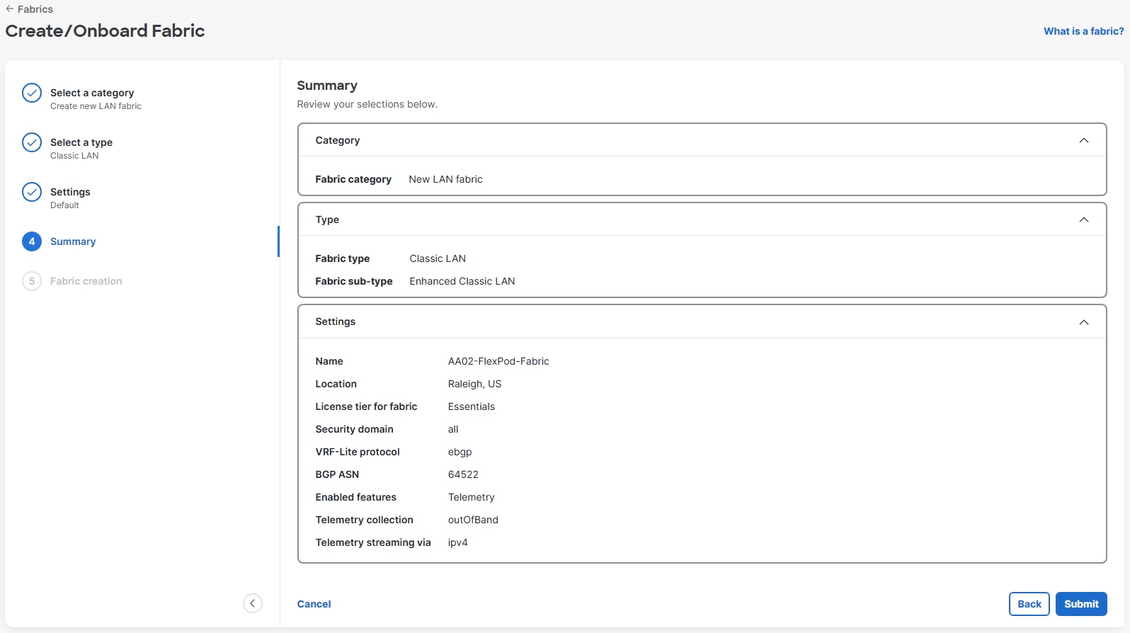
Step 6. For Configuration mode, keep the Default option. Specify Name, Location, and BGP ASN for the fabric. In this example, the ASN used is from the BGP Private ASN range. Also select the Licensing tier for fabric from the options available. Start with Essentials. This can be changed later if necessary. Click the ? icon to see the features available in each tier. Leave Telemetry enabled. Click Next.
Note: Leave the Cisco Hypershield Switch DPU feature in the Cisco Nexus 9324C-SE1U switches disabled for now. It can be enabled when used. This feature would require a higher licensing tier.
Step 7. In the Summary view, verify the settings and click Submit.
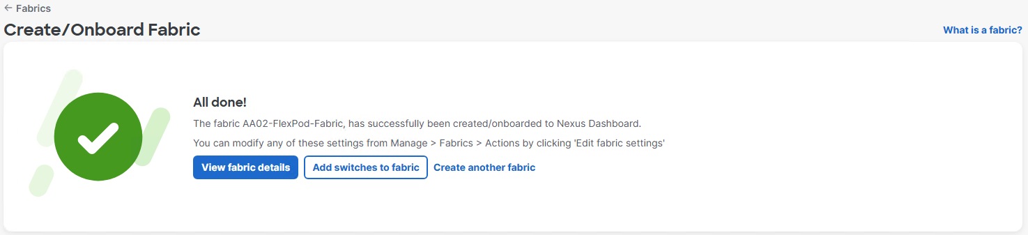
Step 8. When Fabric Creation completes, you should see the following:
Step 9. Select Manage > Fabrics on the left and then select the FlexPod fabric radio button. From the Actions drop-down list, select Edit fabric settings. Select the Fabric management tab and the Manageability tab underneath. Add the DNS Server IPs, DNS Server VRF (management), NTP Server IPs and the NTP Server VRF (management). Select the Spanning Tree tab. Use the Spanning Tree Bridge Priority pulldown to select 32768, the NXOS default, or an alternative priority determined by your fabric plan. Click Save.
Step 10. Select the FlexPod fabric radio button. From the Actions drop-down list, select Edit fabric settings. Select the Fabric management tab and the Freeform tab underneath. To enable the udld feature, enter “feature udld” in the Aggregation Pre-Interfaces Freeform Config box and hit Enter. To turn on NTP distribution, enter “ntp master <stratum level>” in the Aggregation Pre-Interfaces Freeform Config box and click Save.
Note: Turning on NTP distribution makes every L3 interface (mgmt0, all SVIs and HSRP gateways) in the switch an NTP server.
Step 11. From the Manage > Fabrics view, click the fabric name to add switches to the fabric.
Step 12. Click Actions and select Add switches from the drop-down list.
Step 13. Specify Seed IP, Username, and Password. Adjust Max hops as needed. Uncheck Preserve config. Click Discover switches. On the popup, click Confirm.
Note: When adjusting Max hops, consider that a larger fabric can take a long time to discover.
Step 14. Select the two switches to be added. Click Add switches.
Step 15. The two switches will be rebooted and added to the fabric. When the switches have been added, click Close. Wait for the switches to complete reboot.
Step 16. Select the Inventory tab. Using the checkboxes on the left, select the two switches in the list and using the lower Actions drop-down list, select Set role. Select Aggregation and click Select. Click Ok on the popup warning.
Step 17. Select the checkbox to the left of the first switch. Using the lower Actions drop-down list, select vPC pairing. Select the radio button for the second switch and click Save. Click Ok on the popup warning.
Step 18. Click the Configuration policies tab. Using the lower Actions drop-down list, select Add policy. Using the checkboxes, select both switches and click Next. Enter an optional Description. Click No Policy Selected >. In the search box, type clock and select clock_timezone. Click Select. Fill in the Name of Time Zone, Hours Offset, and Minutes Offset according to your local timezone. Click Save.
Step 19. Optionally, if you want to configure Daylight Savings Time, using the lower Actions drop-down list, select Add policy. Using the checkboxes, select both switches and click Next. Enter an optional Description. Click No Policy Selected >. In the search box, type clock and select clock_summertime. Click Select. Fill in the Summertime String according to your local timezone and click Save.
Step 20. Click the Inventory tab and wait for the switches’ Discovery status to become Ok.
Step 21. Click the higher of the two Actions buttons and select Recalculate and deploy from the drop-down list. If it says one is already in progress, wait a few minutes and repeat the steps. You should see the Fabric as Out-of-sync with some Pending Config (lines of config) change. You can click on one or both of the Pending config fields to see the configuration being added to the switch. Click Deploy all.
Step 22. When deployment is completed, click Close.
Step 23. Nexus Dashboard will identify issues in hardware, connectivity, software and so on, reflected by the Anomaly level. To view the flagged anomalies, navigate to Anomalies in the top menu bar. Address each anomaly to prevent issues later, either by resolving them or acknowledging them.
Step 24. Review the Advisories and resolve or acknowledge them.
Procedure 2. Deploy Fabric vPCs
Step 1. In the Nexus Dashboard web interface, select Manage > Fabrics. Select the FlexPod Fabric link to go to the Fabric Overview. Select the Connectivity tab. The Interfaces tab should be selected underneath.
Step 2. Click the lower of the two Actions drop-down lists and select Create interface.
Step 3. To create the vPC for the first storage controller, under Create interface, for Type select Virtual Port Channel (VPC). For Mode, leave Trunk selected. Under “Select a VPC pair,” select the vPC pair with your two switches. For VPC ID, put in an ID (it is recommended to key it off the module and port number – 11 for module 1 port 1 from Eth1/1). Check Enable Config Mirroring. Enter the port on switch A connected to storage controller 01 (Eth1/1) in Peer-1 Member Interfaces. This value is automatically filled in in Peer-2 Member Interfaces. Enter the name of storage controller 01 for Peer-1 PO Description. This value is automatically filled in in Peer-2 PO Description. Do not check Copy PO Description. Do not set a Native Vlan. Click Save.
Step 4. Located above Create interface, click Back.
Step 5. Repeat Steps 2-4 to create the vPC for storage controller 02.
Step 6. Click the lower of the two Actions drop-down lists and select Create interface.
Step 7. To create the vPC for the first Cisco UCS Fabric Interconnect (FI), under Create interface, for Type select Virtual Port Channel (VPC). For Mode, leave Trunk selected. Under “Select a VPC pair,” select the vPC pair with your two switches. For VPC ID, put in an ID (it is recommended to key it off the module and port number – 15 for module 1 port 5 from Eth1/5). Check Enable Config Mirroring. Enter the port on switch A connected to FI A (Eth1/5) in Peer-1 Member Interfaces. This value is automatically filled in in Peer-2 Member Interfaces. Enter the name of FI A for Peer-1 PO Description. This value is automatically filled in in Peer-2 PO Description. Do not check Copy PO Description. Scroll down and set a Native Vlan (2). Click Save.
Step 8. Located above Create interface, click Back.
Step 9. Repeat Steps 6-8 to create the vPC for FI B.
Step 10. Repeat Steps 6-8 to create an L2 Uplink vPC with three exceptions. When creating the vPC, set Enable BPDU Guard to default. Uncheck Enable Port Type Fast and in the Peer-1 PO Freeform Config box, enter “spanning-tree port type normal.” This will be mirrored in the Peer-2 PO Freeform Config box. In this lab validation, port 24 on each switch was used for the uplink in vPC124. Click Save then click Back.
Step 11. From the upper Actions drop-down list, select Recalculate and deploy. Review the Pending config if desired and click Deploy all.
Step 12. When the Deployment is completed, click Close.
The vPCs should now all show In sync.
Procedure 3. Create and Deploy Native and OOB-MGMT VLAN Networks
Step 1. In Nexus Dashboard from the FlexPod Fabric, select the Segmentation and security tab. The Networks tab should be selected.
Step 2. From the lower Actions drop-down list, select Create.
Step 3. Under Create network, for Network name enter Native-VLAN. For Network mode select Layer 2 only. For VLAN ID, enter the Native VLAN ID (2). For VLAN Name, enter Native. Click Create.
Step 4. Repeat Steps 2 and 3 to create the OOB-MGMT-VLAN Network.
Step 5. To deploy the Native-VLAN to the FI and uplink port-channels, select the checkbox to the left of Native-VLAN and using the lower Actions drop-down list, select Multi-Attach. Select the checkbox to the left of Nexus Switch A and click Next. Click Select Interfaces. Select 100 Rows per page and scroll down to the bottom of the list. Using the checkboxes on the left, select the port-channels for the FIs and the Uplink. Click Save.
Step 6. Click Next.
Step 7. Click Save.
Step 8. Review the Pending config if desired and click Deploy all.
Step 9. When the Deployment is completed, click Close.
Step 10. To deploy the OOB-MGMT-VLAN to the FI and Uplink port-channels, select the checkbox to the left of OOB-MGMT-VLAN and using the lower Actions drop-down list, select Multi-Attach. Select the checkbox to the left of Nexus Switch A and click Next. Click Select Interfaces. Select 100 Rows per page and scroll down to the bottom of the list. Using the checkboxes on the left, select the port-channels for the FIs and the Uplink. Click Save.
Note: This will pipe the OOB-MGMT VLAN into the FIs allowing In-Band vKVMs to be placed in the OOB-MGMT subnet. Virtual Machines can also now run on the OOB-MGMT VLAN and subnet.
Step 11. Click Next.
Step 12. Click Save.
Step 13. Review the Pending config if desired and click Deploy all.
Step 14. When the Deployment is completed, click Close.
Procedure 4. Add Specific Descriptions and Features to Interfaces
This procedure will add specific port numbers to the vPC port-channel member interfaces and also enable UDLD on the FI interfaces when copper cables are used with the FIs.
Step 1. In the Nexus Dashboard Fabric view, select the Connectivity tab and then the Interfaces tab underneath.
Step 2. Using the checkboxes on the left, select all of the vPC port-channel member interfaces except the vPC peer-link port-channel members. Then using the lower Actions drop-down list, select Edit configuration. For each interface, in the Interface Description field add the device name, a colon, and the port number on the device where the port is connected (for example, AA02-A90-01:e6a or AA02-6664-A:Eth1/63). If the interface is connected to a UCS FI with copper twinnax cables, add “udld enable” to the Freeform Config field for the FI interfaces. Click Save & Next. Continue until Save & Next becomes Save.
Note: UDLD is automatically enabled on interfaces with fiber cables. If you add “udld enable” to a fiber interface, the switch will ignore the command and will no longer be “In sync” with Nexus Dashboard.
Step 3. Click Save. Click Deploy. Review the Pending config if desired and click Deploy config. After deployment completes, all interfaces should now show “In sync.”
Procedure 5. Deploy Cisco Live Protect
Live Protect is a Cisco Nexus feature that enables rapid mitigation of certain security advisories on eligible Nexus 9000 Series switches. By deploying compensating-control policies directly to switches, you can protect your network from active threats without requiring a maintenance window or immediate software upgrade.
For more information, see Cisco Nexus Dashboard Live Protect Overview and Cisco Nexus 9000 Series NX-OS Security Configuration Guide.
Live Protect identifies security advisories affecting your devices. If an advisory can be mitigated, the system provides a signed compensating control (Tetragon policy) in the form of an RPM package. You can deploy these controls to eligible switches in either monitor or protect mode. Live Protect tracks the status and impact of each control, providing visibility through the Cisco Nexus user interface.
● Protect mode — Policy actively blocks threat attempts, enforcing protection on the device.
● Monitor mode — Policy logs exploit attempts but does not enforce protection.
● Disable mode — Disables specific policy on the switch without removing the policy.
Step 1. In Nexus Dashboard LAN, select Manage > Device Security > Security advisories > Devices.
Step 2. Select the checkboxes to the left of the FlexPod switches and click Enable Live Protect. This will enable feature nxsecure in the switches.
Step 3. When Security Advisories come up, you can deploy the compensating control and either monitor or protect.
Procedure 6. Create Scheduled Nexus Dashboard Backups
Step 1. In Nexus Dashboard, select Admin > Backup and Restore. Select the Backup schedules tab.
Step 2. Using the Actions drop-down list, select Create backup schedule. Give the schedule a Name (for example, daily-config-backup). Leave Config-Only selected. Under Remote storage location, click Create remote storage location.
Step 3. In this example, an SCP server is used. Give the storage location a Name (for example, flexpod-lab-backup). Leave SFTP/SCP Server selected. For Protocol, select SCP. For Hostname/IP, input the IP address of the SCP server. For Default path, enter the path of the backup location. Enter the Username and corresponding Password for the SCP server. Click Save. On the popup, click Ok.
Step 4. Back on the Create backup schedule window, select the Remote storage location just created. Enter a minimum 8-character Encryption key. Enter a Scheduler date and time. Select a Frequency. Click Create.
NetApp ONTAP Storage Configuration
This chapter contains the following:
See the following section (NetApp Hardware Universe) for planning the physical location of the storage systems:
● Site Preparation
● System Connectivity Requirements
● Circuit Breaker, Power Outlet Balancing, System Cabinet Power Cord Plugs, and Console Pinout Requirements
● AFF Series Systems
The NetApp Hardware Universe (HWU) application provides supported hardware and software components for any specific ONTAP version. It also provides configuration information for all the NetApp storage appliances currently supported by ONTAP software and a table of component compatibilities.
To confirm that the hardware and software components that you would like to use are supported with the version of ONTAP that you plan to install, follow these steps at the NetApp Support site.
Procedure 1. Confirm hardware and software components
Step 1. Access the HWU application to view the System Configuration guides. Click the Products tab to select the Platforms menu to view the compatibility between different versions of the ONTAP software and the NetApp storage appliances with your desired specifications.
Step 2. Alternatively, to compare components by storage appliance, click Utilities and select Compare Storage Systems.
Controllers
Follow the physical installation procedures for the controllers found here: https://docs.netapp.com/us-en/ontap-systems/index.html.
NetApp storage systems support a wide variety of disk shelves and disk drives. The complete list of disk shelves that are supported by the NetApp AFF A90 is available at the NetApp Support site.
When using SAS disk shelves with NetApp storage controllers, go to: https://docs.netapp.com/us-en/ontap-systems/sas3/install-new-system.html for proper cabling guidelines.
When using NVMe drive shelves with NetApp storage controllers, go to: https://docs.netapp.com/us-en/ontap-systems/ns224/hot-add-shelf.html for installation and servicing guidelines.45
Complete Configuration Worksheet
Before running the setup script, complete the Cluster setup worksheet in the NetApp ONTAP 9 Documentation Center. You must have access to the NetApp Support site to open the cluster setup worksheet.
Configure ONTAP Nodes
Before running the setup script, review the configuration worksheets in the Software setup section of the ONTAP 9 Documentation Center to learn about configuring ONTAP. Table 6 lists the information needed to configure two ONTAP nodes. Customize the cluster-detail values with the information applicable to your deployment.
Table 6. ONTAP Software Installation Prerequisites
| Cluster Detail |
Cluster Detail Value |
| Cluster node 01 IP address |
<node01-mgmt-ip> |
| Cluster node 01 netmask |
<node01-mgmt-mask> |
| Cluster node 01 gateway |
<node01-mgmt-gateway> |
| Cluster node 02 IP address |
<node02-mgmt-ip> |
| Cluster node 02 netmask |
<node02-mgmt-mask> |
| Cluster node 02 gateway |
<node02-mgmt-gateway> |
| ONTAP 9.18.1 URL (http server hosting ONTAP software) |
<url-boot-software> |
Procedure 2. Configure Node 01
Step 1. Connect to the storage system console port. You should see a Loader-A prompt. However, if the storage system is in a reboot loop, press Ctrl-C to exit the autoboot loop when the following message displays:
Starting AUTOBOOT press Ctrl-C to abort…
Step 2. Allow the system to boot up.
autoboot
Step 3. Press Ctrl-C when prompted.
Note: Use the latest NetApp ONTAP release patch. In this example, it is 9.18.1P1. If NetApp ONTAP 9.18.1P1 is not the version of the software being booted, continue with the following steps to install new software. If NetApp ONTAP 9.18.1P1 is the version being booted, select option 8 and y to reboot the node, then continue with section Set Up Node.
Step 4. To install new software, select option 7 from the menu.
Step 5. Enter y to continue the installation.
Step 6. Select e0M for the network port for the download.
Step 7. Enter n to skip the reboot.
Step 8. Select option 7 from the menu: Install new software first
Step 9. Enter y to continue the installation.
Step 10. Enter the IP address, netmask, and default gateway for e0M.
Enter the IP address for port e0M: <node01-mgmt-ip>
Enter the netmask for port e0M: <node01-mgmt-mask>
Enter the IP address of the default gateway: <node01-mgmt-gateway>
Step 11. Enter the URL where the software can be found.
Note: The e0M interface should be connected to the management network and the web server must be reachable (using ping) from node 01.
<url-boot-software>
Step 12. Press Enter for the user name, indicating no user name.
Step 13. Enter y to set the newly installed software as the default to be used for subsequent reboots.
Step 14. Enter y to reboot the node now.
Note: When installing new software, the system might perform firmware upgrades to the BIOS and adapter cards, causing reboots and possible stops at the Loader-A prompt. If these actions occur, the system might deviate from this procedure.
Note: During the ONTAP installation a prompt to reboot the node requests a Y/N response.
Step 15. Press Ctrl-C when the following message displays:
Press Ctrl-C for Boot Menu
Step 16. Select option 4 for Clean Configuration and Initialize All Disks.
Step 17. Enter y to zero disks, reset config, and install a new file system.
Step 18. Enter yes to erase all the data on the disks.
Note: When initialization and creation of root aggregate is complete, the storage system reboots. You can continue with the configuration of node 02 while the initialization and creation of the root aggregate for node 01 is in progress. For more information about root aggregate and disk partitioning, please refer to the following NetApp ONTAP documentation on root-data partitioning: https://docs.netapp.com/us-en/ontap/concepts/root-data-partitioning-concept.html
Procedure 3. Configure Node 02
Step 1. Connect to the storage system console port. You should see a Loader-B prompt. However, if the storage system is in a reboot loop, press Ctrl-C to exit the autoboot loop when the following message displays:
Starting AUTOBOOT press Ctrl-C to abort…
Step 2. Allow the system to boot up.
autoboot
Step 3. Press Ctrl-C when prompted.
Note: If NetApp ONTAP 9.18.1P1 is not the version of the software being booted, continue with the following steps to install new software. If NetApp ONTAP 9.18.1P1 is the version being booted, select option 8 and y to reboot the node. Continue with section Set Up Node.
Step 4. To install new software, select option 7.
Step 5. Enter y to continue the installation.
Step 6. Select e0M for the network port you want to use for the download.
Step 7. Enter n to skip the reboot.
Step 8. Select option 7: Install new software first
Step 9. Enter y to continue the installation.
Step 10. Enter the IP address, netmask, and default gateway for e0M.
Enter the IP address for port e0M: <node02-mgmt-ip>
Enter the netmask for port e0M: <node02-mgmt-mask>
Enter the IP address of the default gateway: <node02-mgmt-gateway>
Step 11. Enter the URL where the software can be found.
Note: The web server must be reachable (ping) from node 02.
<url-boot-software>
Step 12. Press Enter for the username, indicating no username.
Step 13. Enter y to set the newly installed software as the default to be used for subsequent reboots.
Step 14. Enter y to reboot the node now.
Note: When installing new software, the system might perform firmware upgrades to the BIOS and adapter cards, causing reboots and possible stops at the Loader-B prompt. If these actions occur, the system might deviate from this procedure.
Note: During the ONTAP installation a prompt to reboot the node requests a Y/N response.
Step 15. Press Ctrl-C when you see this message:
Press Ctrl-C for Boot Menu
Step 16. Select option 4 for Clean Configuration and Initialize All Disks.
Step 17. Enter y to zero disks, reset config, and install a new file system.
Step 18. Enter yes to erase all the data on the disks.
Note: When initialization and creation of root aggregate is complete, the storage system reboots. For more information about root aggregate and disk partitioning, please refer to the following ONTAP documentation on root-data partitioning. https://docs.netapp.com/us-en/ontap/concepts/root-data-partitioning-concept.html
Step 1. From a console port program attached to the storage controller A (node 01) console port, run the node setup script. This script appears when ONTAP 9.18.1 P1boots on the node for the first time.
Step 2. Follow the prompts to set up node 01:
Welcome to the cluster setup wizard.
You can enter the following commands at any time:
"help" or "?" - if you want to have a question clarified,
"back" - if you want to change previously answered questions, and
"exit" or "quit" - if you want to quit the setup wizard.
Any changes you made before quitting will be saved.
You can return to cluster setup at any time by typing “cluster setup”.
To accept a default or omit a question, do not enter a value.
This system will send event messages and weekly reports to NetApp Technical Support.
To disable this feature, enter "autosupport modify -support disable" within 24 hours.
Enabling AutoSupport can significantly speed problem determination and resolution should a problem occur on your system.
For further information on AutoSupport, see:
http://support.netapp.com/autosupport/
Type yes to confirm and continue {yes}: yes
Enter the node management interface port [e0M]: Enter
Enter the node management interface IP address: <node01-mgmt-ip>
Enter the node management interface netmask: <node01-mgmt-mask>
Enter the node management interface default gateway: <node01-mgmt-gateway>
A node management interface on port e0M with IP address <node01-mgmt-ip> has been created.
Use your web browser to complete cluster setup by accesing https://<node01-mgmt-ip>
Otherwise press Enter to complete cluster setup using the command line interface:
Step 3. To complete cluster setup, open a web browser and navigate to https://<node01-mgmt-ip>.
Table 7. Cluster Create in ONTAP Prerequisites
| Cluster Detail |
Cluster Detail Value |
| Cluster name |
<clustername> |
| Cluster Admin SVM |
<cluster-adm-svm> |
| ONTAP One license |
<cluster-license-key> |
| Cluster management IP address |
<clustermgmt-ip> |
| Cluster management netmask |
<clustermgmt-mask> |
| Cluster management gateway |
<clustermgmt-gateway> |
| Cluster node 01 IP address |
<node01-mgmt-ip> |
| Cluster node 01 netmask |
<node01-mgmt-mask> |
| Cluster node 01 gateway |
<node01-mgmt-gateway> |
| Cluster node 02 IP address |
<node02-mgmt-ip> |
| Cluster node 02 netmask |
<node02-mgmt-mask> |
| Cluster node 02 gateway |
<node02-mgmt-gateway> |
| Node 01 service processor IP address |
<node01-sp-ip> |
| Node 01 service processor network mask |
<node01-sp-mask> |
| Node 01 service processor gateway |
<node01-sp-gateway> |
| Node 02 service processor IP address |
<node02-sp-ip> |
| Node 02 service processor network mask |
<node02-sp-mask> |
| Node 02 service processor gateway |
<node02-sp-gateway> |
| Node 01 node name |
<st-node01> |
| Node 02 node name |
<st-node02> |
| DNS domain name |
<dns-domain-name> |
| DNS server IP address |
<dns-ip> |
| NTP server A IP address |
<switch-a-ntp-ip> |
| NTP server B IP address |
<switch-b-ntp-ip> |
| SNMPv3 User |
<snmp-v3-usr> |
| SNMPv3 Authentication Protocol |
<snmp-v3-auth-proto> |
| SNMPv3 Privacy Protocol |
<snmpv3-priv-proto> |
Note: Cluster setup can also be performed using the CLI. This document describes the cluster setup using the NetApp ONTAP System Manager guided setup.
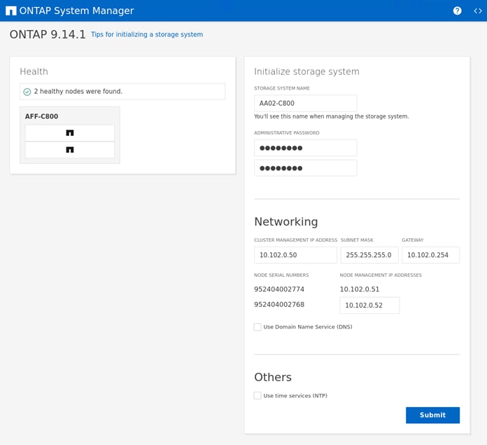
Step 4. Complete the required information on the Initialize Storage System screen:
Step 5. In the Cluster Screen:
a. Enter the cluster name and administrator password.
b. Complete the Networking information for the cluster and each node.
c. Check the box for Use Domain Name Service (DNS) and enter the IP addresses of the DNS servers in a comma separated list.
d. Check the box for Use time services (NTP) and enter the IP addresses of the time servers in a comma separated list.
Note: The nodes should be discovered automatically; if they are not, Refresh the browser page. By default, the cluster interfaces are created on all the new factory shipping storage controllers.
Note: If all the nodes are not discovered, then configure the cluster using the command line.
Note: The node management interface can be on the same subnet as the cluster management interface, or it can be on a different subnet. In this document, we assume that it is on the same subnet.
Step 6. Click Submit.
Note: A few minutes will pass while the cluster is configured. When prompted, login to NetApp ONTAP System Manager to continue the cluster configuration.
Procedure 5. Manual ONTAP Storage Configuration – Base Config
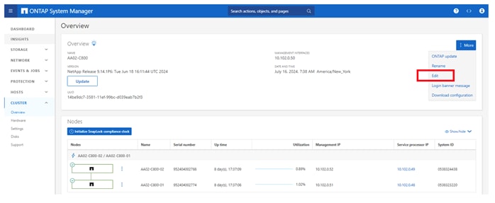
Step 1. From the Dashboard click the CLUSTER menu on the left and select Overview.
Step 2. Click the More ellipsis button in the Overview pane at the top right of the screen and select Edit.
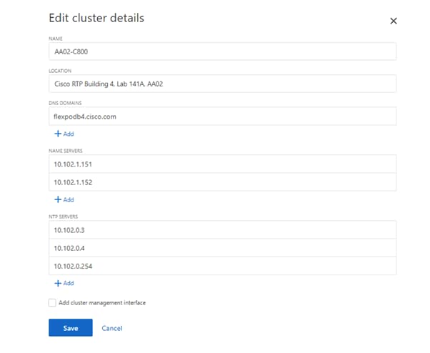
Step 3. Add additional cluster configuration details and click Save to make the changes persistent:
a. DNS domain name
b. DNS server IP addresses
c. NTP server IP addresses
Note: DNS and NTP server IP addresses can be added individually or with a comma separated list on a single line.
Note: For redundancy and best service NetApp recommends that you associate at least three NTP servers with the cluster. Otherwise, you will observe an alert/warning in AIQUM stating “NTP Server Count is Low.”
Step 4. Click Save to make the changes persistent.
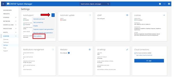
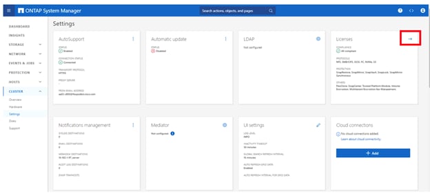
Step 5. Select the Settings menu under the CLUSTER menu.
Step 6. If AutoSupport was not configured during the initial setup, click the ellipsis in the AutoSupport tile and select More options.
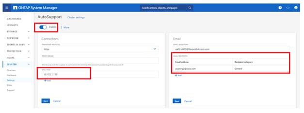
Step 7. To enable AutoSupport click the slider.
Step 8. In the Connections tile to the left, click Edit to change the transport protocol, add a proxy server address and a mail host as needed.
Step 9. Click Save to enable the changes.
Step 10. In the Email tile to the right, click Edit and enter the desired email information:
Email send from address
a. Email recipient addresses
b. Recipient category
Step 11. Click Save when complete.
Step 12. Select CLUSTER > Settings at the top left of the page to return to the cluster settings page.
Step 13. Locate the Licenses tile on the right and click the detail arrow.
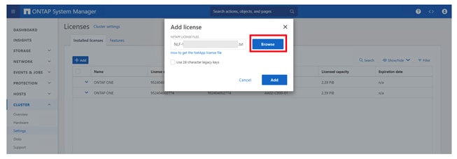
Step 14. Click Add to add the desired licenses to the cluster. Select Browse and choose the NetApp License File you downloaded.
Step 15. Click Add when complete.
Step 16. If you have license keys you want to add, select Use 28-character legacy keys and enter the keys.
Note: NetApp ONTAP 9.10.1 and later for FAS/AFF storage systems uses a new file-based licensing solution to enable per-node NetApp ONTAP features. The new license key format is referred to as a NetApp License File, or NLF. For more information, go to: NetApp ONTAP 9.10.1 and later Licensing Overview - NetApp Knowledge Base.
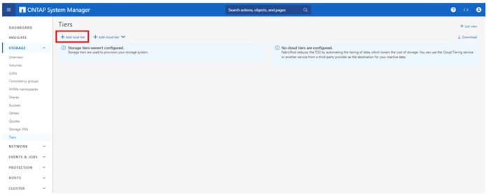
Step 17. Configure storage aggregates by selecting the STORAGE menu on the left and selecting Tiers.
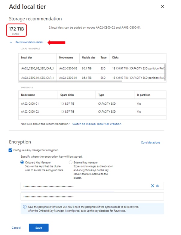
Step 18. Click Add local tier and allow NetApp ONTAP System Manager to recommend a storage aggregate configuration.
Step 19. NetApp ONTAP will use best practices to recommend an aggregate layout. Click the Recommendation details link to view the aggregate information.
Step 20. Optionally, enable NetApp Aggregate Encryption (NAE) by checking the box for Configure Onboard Key Manager for encryption.
Step 21. Enter and confirm the passphrase and save it in a secure location for future use.
Step 22. Click Save to make the configuration persistent.
Note: Aggregate encryption may not be supported for all deployments. Please review the NetApp Encryption Power Guide and the Security Hardening Guide for NetApp ONTAP 9 (TR-4569) to help determine if aggregate encryption is right for your environment.
Procedure 6. Log into the Cluster
Step 1. Open an SSH connection to either the cluster IP or the host name.
Step 2. Log into the admin user with the password you provided earlier.
Procedure 7. Verify Storage Failover
Step 1. Verify the status of the storage failover:
storage failover show
Note: Both <st-node01> and <st-node02> must be capable of performing a takeover. Continue with step 2 if the nodes can perform a takeover.
Step 2. Enable failover on one of the two nodes if it was not completed during the installation:
storage failover modify -node <st-node01> -enabled true
Note: Enabling failover on one node enables it for both nodes.
Step 3. Verify the HA status for a two-node cluster:
Note: This step is not applicable for clusters with more than two nodes.
cluster ha show
Step 4. If HA is not configured use the below commands. Only enable HA mode for two-node clusters. Do not run this command for clusters with more than two nodes because it causes problems with failover:
cluster ha modify -configured true
Do you want to continue? {y|n}: y
Procedure 8. Zero All Spare Disks
Step 1. To zero all spare disks in the cluster, run the following command:
disk zerospares
Note: Advanced Data Partitioning creates a root partition and two data partitions on each SSD drive in an AFF configuration. Disk auto-assign should have assigned one data partition to each node in an HA pair. If a different disk assignment is required, disk auto-assignment must be disabled on both nodes in the HA pair by running the disk option modify command. Spare partitions can then be moved from one node to another by running the disk removeowner and disk assign commands.
Procedure 9. Set Up Service Processor Network Interface
Step 1. To assign a static IPv4 address to the Service Processor on each node, run the following commands:
system service-processor network modify –node <st-node01> -address-family IPv4 –enable true –dhcp none –ip-address <node01-sp-ip> -netmask <node01-sp-mask> -gateway <node01-sp-gateway>
system service-processor network modify –node <st-node02> -address-family IPv4 –enable true –dhcp none –ip-address <node02-sp-ip> -netmask <node02-sp-mask> -gateway <node02-sp-gateway>
Note: The Service Processor IP addresses should be in the same subnet as the node management IP addresses.
Procedure 10. Create Manual Provisioned Data Aggregates (Optional)
An aggregate containing the root volume is created during the NetApp ONTAP setup process. To manually create additional data aggregates, determine the aggregate name, the node on which to create it, and the number of disks it should contain. Options for disk class include solid-state, performance, capacity, array, and archive.
Step 1. Run the following command to get the disk class information from ONTAP storage system:
storage disk show -fields class
Step 2. To create data aggregates, run the following commands:
storage aggregate create -aggregate <aggr1_node01> -node <st-node01> -diskcount <num-disks> -diskclass solid-state
storage aggregate create -aggregate <aggr1_node02> -node <st-node02> -diskcount <num-disks> -diskclass solid-state
Note: You should have the minimum number of hot spare disks for the recommended hot spare disk partitions for their aggregate.
Note: For all-flash aggregates, you should have a minimum of one hot spare disk or disk partition. For non-flash homogenous aggregates, you should have a minimum of two hot spare disks or disk partitions. For Flash Pool aggregates, you should have a minimum of two hot spare disks or disk partitions for each disk type.
Note: In an AFF configuration with a small number of SSDs, you might want to create an aggregate with all, but one remaining disk (spare) assigned to the controller.
Note: The aggregate cannot be created until disk zeroing completes. Run the storage aggregate show command to display the aggregate creation status. Do not proceed until both aggr1_node01 and aggr1_node02 are online.
Procedure 11. Remove Default Broadcast Domains
By default, all network ports are included in separate default broadcast domain. Network ports used for data services (for example, e6a, e6b, and so on) should be removed from their default broadcast domain and that broadcast domain should be deleted.
Step 1. To perform this task, run the following commands:
network port broadcast-domain delete -broadcast-domain <Default-N> -ipspace Default
network port broadcast-domain show
Note: Delete the Default broadcast domains with Network ports (Default-1, Default-2, and so on). This does not include Cluster ports and management ports.
Procedure 12. Disable Flow Control on 25/100GbE Data Ports
Step 1. Run the following command to configure the ports on node 01:
network port modify -node <st-node01> -port e6a,e6b -flowcontrol-admin none
Step 2. Run the following command to configure the ports on node 02:
network port modify -node <st-node02> -port e6a,e6b -flowcontrol-admin none
Note: Disable flow control only on ports that are used for data traffic.
Procedure 13. Disable Auto-Negotiate on Fibre Channel Ports (Required only for FC configuration)
Step 1. Disable each FC adapter in the controllers with the fcp adapter modify command.
fcp adapter modify -node <st-node01> -adapter 8a –status-admin down
fcp adapter modify -node <st-node01> -adapter 8b –status-admin down
fcp adapter modify -node <st-node01> -adapter 8c –status-admin down
fcp adapter modify -node <st-node01> -adapter 8d –status-admin down
fcp adapter modify -node <st-node02> -adapter 8a –status-admin down
fcp adapter modify -node <st-node02> -adapter 8b –status-admin down
fcp adapter modify -node <st-node02> -adapter 8c –status-admin down
fcp adapter modify -node <st-node02> -adapter 8d –status-admin down
Step 2. Set the desired speed on the adapter and return it to the online state.
fcp adapter modify -node <st-node01> -adapter 8a -speed 64 -status-admin up
fcp adapter modify -node <st-node01> -adapter 8b -speed 64 -status-admin up
fcp adapter modify -node <st-node01> -adapter 8c -speed 64 -status-admin up
fcp adapter modify -node <st-node01> -adapter 8d -speed 64 -status-admin up
fcp adapter modify -node <st-node02> -adapter 8a -speed 64 -status-admin up
fcp adapter modify -node <st-node02> -adapter 8b -speed 64 -status-admin up
fcp adapter modify -node <st-node02> -adapter 8c -speed 64 -status-admin up
fcp adapter modify -node <st-node02> -adapter 8d -speed 64 -status-admin up
Procedure 14. Enable Cisco Discovery Protocol
Step 1. To enable the Cisco Discovery Protocol (CDP) on the NetApp storage controllers, run the following command:
node run -node * options cdpd.enable on
Procedure 15. Enable Link-layer Discovery Protocol on all Ethernet Ports
Step 1. Enable LLDP on all ports of all nodes in the cluster:
node run -node * options lldp.enable on
Procedure 16. Configure Timezone
Step 1. Set the time zone for the cluster.
timezone -timezone <timezone>
Note: For example, in the eastern United States, the time zone is America/New_York.
Procedure 17. Configure login banner for the NetApp ONTAP Cluster
Step 1. To create login banner for the NetApp ONTAP cluster, run the following command:
security login banner modify -message "Access restricted to authorized users" -vserver <clustername>
Note: If the login banner for the ONTAP cluster is not configured, users will observe a warning in AIQUM stating “Login Banner Disabled.”
Procedure 18. Enable FIPS Mode on the NetApp ONTAP Cluster
NetApp ONTAP is compliant in the Federal Information Processing Standards (FIPS) 140-2 for all SSL connections. When SSL FIPS mode is enabled, SSL communication from NetApp ONTAP to external client or server components outside of NetApp ONTAP will use FIPS compliant crypto for SSL.
Step 1. To enable FIPS mode on the NetApp ONTAP cluster, run the following commands:
set -privilege advanced
security config modify -interface SSL -is-fips-enabled true
set -privilege admin
Note: If FIPS is not enabled on the NetApp ONTAP cluster, the users will observe a warning in AIQUM stating “FIPS Mode Disabled.”
Note: When FIPS mode is enabled, there are related security practices that will be enforced:
◦ Transport Layer Security v1.1 (TLSv1.1) is disabled, and only TLS v1.2 and TLS v1.3 remain enabled.
◦ SNMP users or SNMP traphosts that are non-compliant to FIPS will be deleted automatically.
◦ An SNMPv1 user, SNMPv2c user or SNMPv3 user (with none or MD5 as authentication protocol or none or DES as encryption protocol or both) is non-compliant to FIPS.
◦ An SNMPv1 traphost or SNMPv3 traphost (configured with an SNMPv3 user non-compliant to FIPS) is non-compliant to FIPS.
Procedure 19. Configure Simple Network Management Protocol (SNMP)
Step 1. Configure basic SNMP information, such as the location and contact. When polled, this information is visible as the sysLocation and sysContact variables in SNMP.
snmp contact <snmp-contact>
snmp location <snmp-location>
snmp init 1
options snmp.enable on
Step 2. Configure SNMP traps to send to remote hosts, such as an Active IQ Unified Manager server or another fault management system.
Note: This step works when FIPS mode is disabled on the cluster as an SNMPv1 traphost or SNMPv3 traphost (configured with an SNMPv3 user non-compliant to FIPS) is non-compliant to FIPS.
snmp traphost add <oncommand-um-server-fqdn>
Step 3. Configure SNMP community.
Note: This step works when FIPS mode is disabled as SNMPv1 and SNMPv2c users are non-compliant to FIPS.
system snmp community add -type ro -community-name <snmp-community> -vserver <clustername>
Note: In new installations of NetApp ONTAP, SNMPv1 and SNMPv2c are disabled by default. SNMPv1 and SNMPv2c are enabled after you create an SNMP community.
Note: NetApp ONTAP supports read-only communities.
Procedure 20. Configure SNMPv3 Access
SNMPv3 offers advanced security by using encryption and passphrases. The SNMPv3 users can run SNMP utilities from the traphost using the authentication and privacy settings that they specify.
Note: SNMPv3 user (with none or MD5 as authentication protocol or none or DES as encryption protocol or both) is non-compliant to FIPS. So, when FIPS mode is enabled on the cluster, below are the supported/compliant options for authentication and privacy protocols:
◦ Authentication protocol: sha, sha2-256
◦ Privacy protocol: aes128
Step 1. To configure SNMPv3 access, run the following commands:
security login create -user-or-group-name <<snmp-v3-usr>> -application snmp -authentication-method usm
Enter the authoritative entity's EngineID [local EngineID]:
Which authentication protocol do you want to choose (none, md5, sha, sha2-256) [none]: <<snmp-v3-auth-proto>>
Enter the authentication protocol password (minimum 8 characters long):
Enter the authentication protocol password again:
Which privacy protocol do you want to choose (none, des, aes128) [none]: <<snmpv3-priv-proto>>
Enter privacy protocol password (minimum 8 characters long):
Enter privacy protocol password again:
Note: See the SNMP Configuration Express Guide for additional information when configuring SNMPv3 security users.
Procedure 21. Create Interface Groups
Step 1. To create the LACP interface groups for the 100GbE data interfaces, run the following commands:
network port ifgrp create -node <st-node01> -ifgrp a0a -distr-func port -mode multimode_lacp
network port ifgrp add-port -node <st-node01> -ifgrp a0a -port e6a
network port ifgrp add-port -node <st-node01> -ifgrp a0a -port e6b
network port ifgrp create -node <st-node02> -ifgrp a0a -distr-func port -mode multimode_lacp
network port ifgrp add-port -node <st-node02> -ifgrp a0a -port e6a
network port ifgrp add-port -node <st-node02> -ifgrp a0a -port e6b
Procedure 22. Change MTU on Interface Groups
Step 1. To change the MTU size on the base interface-group ports, run the following commands:
network port modify –node <st-node01> -port a0a –mtu 9000
network port modify –node <st-node02> -port a0a –mtu 9000
Procedure 23. Configure AutoSupport (using ONTAP CLI)
If AutoSupport was not configured previously via System Manager, then perform this step.
Step 1. NetApp AutoSupport sends support summary information to NetApp through HTTPS. To configure AutoSupport using command-line interface, run the following command:
system node autosupport modify -node * -state enable –mail-hosts <mailhost> -from <from-email-address> -to <to-email-address> -transport https -support enable
Procedure 24. Disable HTTP cluster management access.
Step 1. Run the below command to disable HTTP cluster management access.
network interface service-policy remove-service -vserver <clustername> -policy default-management -service management-http
Cisco Intersight Managed Mode Configuration
This chapter contains the following:
● Set up Cisco Intersight Managed Mode on Cisco UCS Fabric Interconnects
● Set up Cisco Intersight Account
● Set up Cisco Intersight Licensing
● Set Up Cisco Intersight Resource Group
● Set Up Cisco Intersight Organization
● Claim Cisco UCS Fabric Interconnects in Cisco Intersight
● Upgrade Fabric Interconnect Firmware using Cisco Intersight
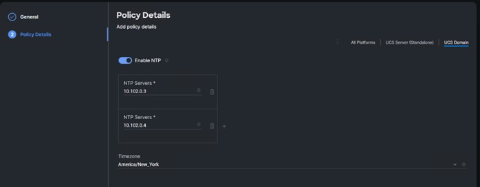
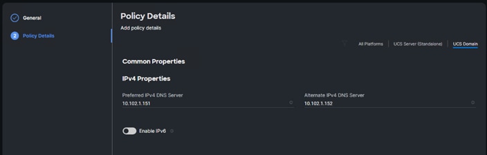
● Configure Network Connectivity Policy
● Create a Cisco UCS Chassis Power Policy
● Create a Cisco UCS Chassis Thermal Policy
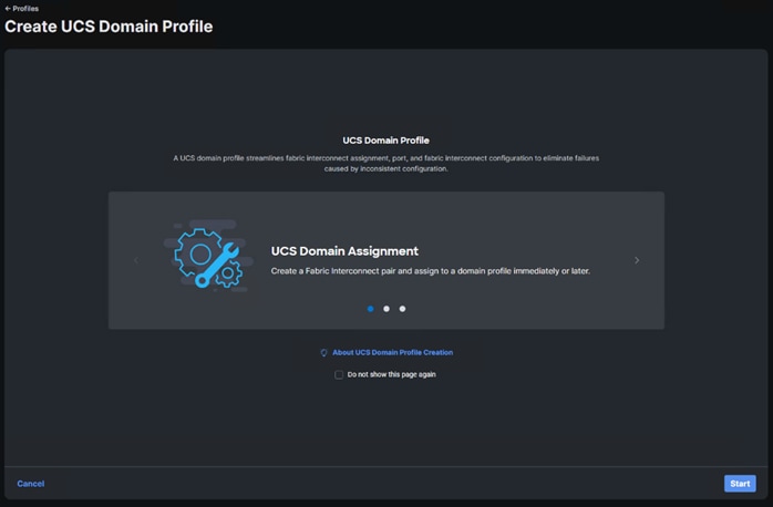
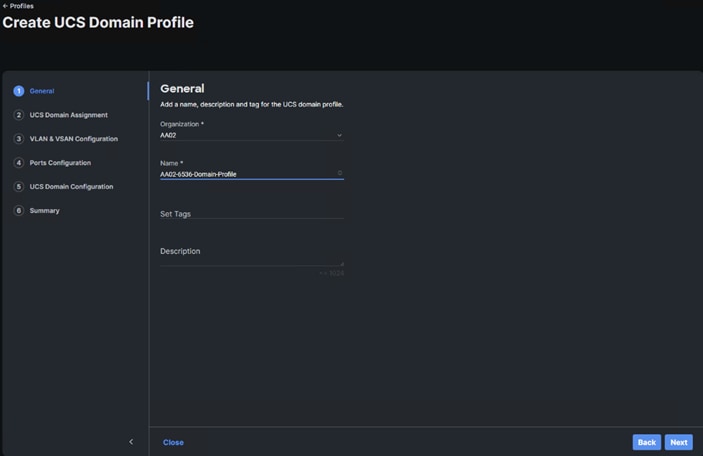
● Create a Cisco UCS Domain Profile Template and Profile
● Deploy the UCS Domain Profile
● Verify Cisco UCS Domain Profile Deployment
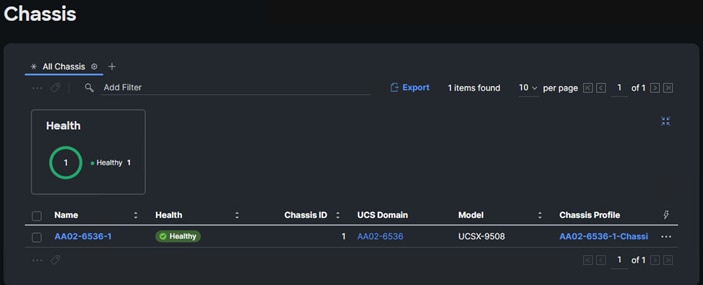
● Configure a Cisco UCS Chassis Profile
The Cisco Intersight platform is a management solution delivered as a service with embedded analytics for Cisco and third-party IT infrastructures. The Cisco Intersight Managed Mode (also referred to as Cisco IMM or Intersight Managed Mode) is an architecture that manages Cisco Unified Computing System (Cisco UCS) fabric interconnect–attached systems through a Redfish-based standard model. Cisco Intersight managed mode standardizes both policy and operation management for Cisco UCS C-Series M7 and Cisco UCS X210c M7 compute nodes used in this deployment guide.
Cisco UCS B-Series M6 servers, connected and managed through Cisco UCS FIs, are also supported by IMM. For a complete list of supported platforms, go to: https://www.cisco.com/c/en/us/td/docs/unified_computing/Intersight/b_Intersight_Managed_Mode_Configuration_Guide/b_intersight_managed_mode_guide_chapter_01010.html
Procedure 1. Set up Cisco Intersight Managed Mode on Cisco UCS Fabric Interconnects
The Cisco UCS fabric interconnects need to be set up to support Cisco Intersight Managed Mode. When converting an existing pair of Cisco UCS fabric interconnects from Cisco UCS Manager mode to Intersight Managed Mode (IMM), first erase the configuration and reboot your system.
Note: Converting fabric interconnects to Cisco Intersight managed mode is a disruptive process, and configuration information will be lost. You are encouraged to make a backup of your existing configuration.
Note: Cisco UCS Fabric Interconnect (FI) Details
| Switch |
OOB IP |
Firmware |
Model |
| AA02-6664-A |
10.102.0.18 |
10.6(2)F |
Cisco UCS-FI-6664 |
| AA02-6664-B |
10.102.0.19 |
10.6(2)F |
Cisco UCS-FI-6664 |
Step 1. Configure Fabric Interconnect A (FI-A). On the Basic System Configuration Dialog screen, set the management mode to Intersight. The remaining settings are similar to those for the Cisco UCS Manager Managed mode (UCSM-Managed). Connect to the console port on the first Cisco UCS fabric interconnect.
Enter the configuration method. (console/gui) ? console
Enter the management mode. (ucsm/intersight)? intersight
The Fabric interconnect will be configured in the intersight managed mode. Choose (y/n) to proceed: y
Enforce strong password? (y/n) [y]: Enter
Enter the password for "admin": <password>
Confirm the password for "admin": <password>
Enter the switch fabric (A/B) []: A
Enter the system name: <ucs-cluster-name>
Physical Switch Mgmt0 IP address : <ucsa-mgmt-ip>
Physical Switch Mgmt0 IPv4 netmask : <ucs-mgmt-mask>
IPv4 address of the default gateway : <ucs-mgmt-gateway>
DNS IP address : <dns-server-1-ip>
Configure the default domain name? (yes/no) [n]: y
Default domain name : <ad-dns-domain-name>
Following configurations will be applied:
Management Mode=intersight
Switch Fabric=A
System Name=<ucs-cluster-name>
Enforced Strong Password=yes
Physical Switch Mgmt0 IP Address=<ucsa-mgmt-ip>
Physical Switch Mgmt0 IP Netmask=<ucs-mgmt-mask>
Default Gateway=<ucs-mgmt-gateway>
DNS Server=<dns-server-1-ip>
Domain Name=<ad-dns-domain-name>
Apply and save the configuration (select 'no' if you want to re-enter)? (yes/no): yes
Step 2. After applying the settings, make sure you can ping the fabric interconnect management IP address. When Fabric Interconnect A is correctly set up and is available, Fabric Interconnect B will automatically discover Fabric Interconnect A during its setup process as shown in the next step.
Step 3. Configure Fabric Interconnect B (FI-B). For the configuration method, select console. Fabric Interconnect B will detect the presence of Fabric Interconnect A and will prompt you to enter the admin password for Fabric Interconnect A. Provide the management IP address for Fabric Interconnect B and apply the configuration. Connect to the console port on the second Cisco UCS fabric interconnect.
Enter the configuration method. (console/gui) ? console
Installer has detected the presence of a peer Fabric interconnect. This Fabric interconnect will be added to the cluster. Continue (y/n) ? y
Enter the admin password of the peer Fabric interconnect: <password>
Connecting to peer Fabric interconnect... done
Retrieving config from peer Fabric interconnect... done
Peer Fabric interconnect Mgmt0 IPv4 Address: <ucsa-mgmt-ip>
Peer Fabric interconnect Mgmt0 IPv4 Netmask: <ucs-mgmt-mask>
Peer FI is IPv4 Cluster enabled. Please Provide Local Fabric Interconnect Mgmt0 IPv4 Address
Physical Switch Mgmt0 IP address : <ucsb-mgmt-ip>
Local fabric interconnect model <fi-model>
Peer fabric interconnect is compatible with the local fabric interconnect. Continuing with the installer...
Apply and save the configuration (select 'no' if you want to re-enter)? (yes/no): yes
Procedure 2. Set up Cisco Intersight Account
If you do not already have an Intersight account with Licensing for this FlexPod, you can create one. If you do not need to create an Intersight account, skip to Procedure 4 below.
Step 1. Go to https://intersight.com and click Create an account. Complete the log in process.
Step 2. Select the appropriate Region and click Next.
Step 3. Read and accept the license agreement. Click Next.
Step 4. Provide an Account Name and click Create.
With a successful creation of the Intersight account, the following page will be displayed:
Note: You can also choose to add the Cisco UCS FIs to an existing Cisco Intersight account.
Procedure 3. Set up Cisco Intersight Licensing
Note: When setting up a new Cisco Intersight account (as explained in this document), the account needs to be enabled for Cisco Smart Software Licensing.
Step 1. Log into the Cisco Smart Licensing portal: https://software.cisco.com/software/smart-licensing/alerts.
Step 2. Verify that the correct virtual account is selected.
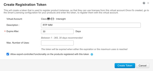
Step 3. Under Inventory > General, click New Token to generate a new token for product registration.
Step 4. Fill in the form and click Create Token. Copy this newly created token using the icon with the arrow pointing to the right and up.
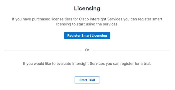
Step 5. In Cisco Intersight, if you created a new account, click Register Smart Licensing.
Step 6. Enter the copied token from the Cisco Smart Licensing portal. Click Next.
Step 7. With Enable Subscription Information selected, click Next. In the popup, click Allow.
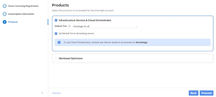
Step 8. Select the products you wish to enable (minimally Infrastructure Service). Use the drop-down list to select the licenses or your Default Tier (for example, Advantage for all).
Step 9. Select Set Default Tier to all existing servers.
Step 10. Click Proceed then click Confirm.
Step 11. When the registration is successful, a Meet Intersight window will appear. Click Let’s Go to review the latest Intersight features or click Skip.
Procedure 4. Set Up Cisco Intersight Resource Group
In this procedure, a Cisco Intersight resource group is created where resources such as targets will be logically grouped. In this deployment, a single resource group is created to host all the resources. When FlexPod tenants are added on top of FlexPod Base, an additional Resource Group will be added for each tenant. This is the resource group for the entire FlexPod.
Step 1. Log into Cisco Intersight.
Step 2. To optionally switch to the Light theme in Intersight, click the icon in the upper right corner of the browser window and select User settings. Select the Light theme and click Save. In this document, the Light theme was used in case the document is printed.
Step 3. Select System > Resource Groups.
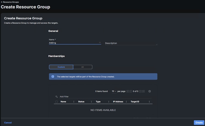
Step 4. Click + Create Resource Group in the top-right corner.
Step 5. Provide a name for the Resource Group (for example, AA02-rg). Make sure Custom is selected under Resources. Click Create.
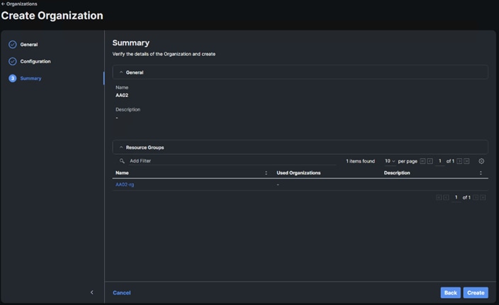
Procedure 5. Set Up Cisco Intersight Organizations
It is recommended to create two organizations for this Intersight account. The first organization will connect to the Resource Group just created. The second organization will contain global policies and pools that can be shared with tenant organizations that will be created later.
Step 1. Select System > Organizations.
Step 2. Click + Create Organization in the top-right corner.
Step 3. Provide a name for the organization (for example, AA02) and click Next. Do not select to Share Resources with Other Organizations.
Step 4. Select the Resource Group created in the last step (for example, AA02-rg) and click Next.
Step 5. Click Create.
Step 6. Click + Create Organization in the top-right corner.
Step 7. Provide a name for the organization (for example, AA02-Policy) and select Share Resources with Other Organizations. Optionally, enter a Description. Click Next.
Step 8. Select the organization created above to share resources with. Click Next.
Step 9. Click Create.
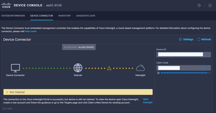
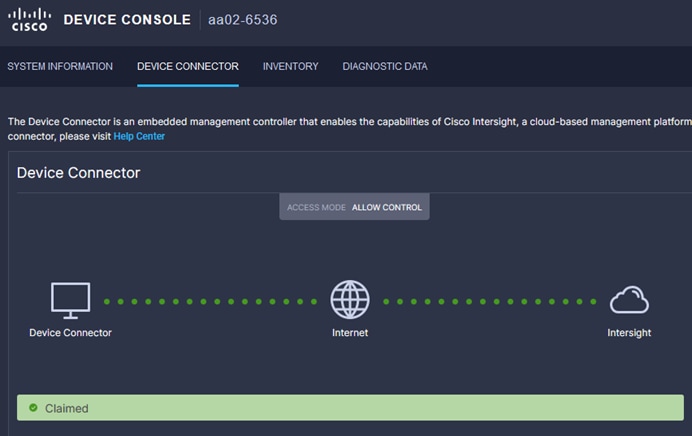
Procedure 6. Claim Cisco UCS Fabric Interconnects in Cisco Intersight
Make sure the initial configuration for the fabric interconnects has been completed. Log into the Fabric Interconnect A Device Console using a web browser to capture the Cisco Intersight connectivity information.
Step 1. Use the management IP address of Fabric Interconnect A to access the device from a web browser and the previously configured admin password to log into the device with https://<ucsa-mgmt-ip>.
Step 2. Under Device Connector, the current device status will show “Not claimed.” Note or copy, the Device ID, and Claim Code information for claiming the device in Cisco Intersight.
Step 3. Log into Cisco Intersight.
Step 4. Select System > Targets.
Step 5. Click Claim a New Target.
Step 6. Select Cisco UCS Domain (Intersight Managed) and click Start.
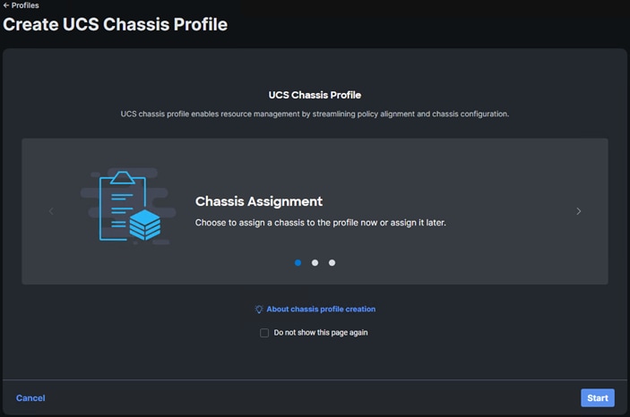
Step 7. Copy and paste the Device ID and Claim Code from the Cisco UCS FI Device Console to Intersight. Input a location. Select the previously created Resource Group and click Claim.
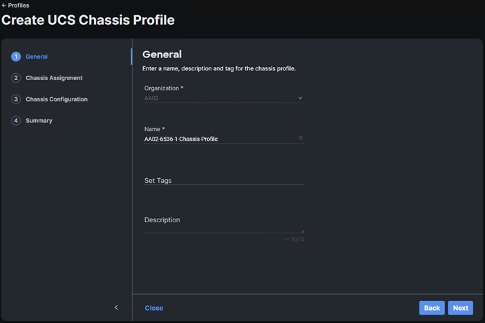
Step 8. With a successful device claim, the Cisco UCS Domain should appear as a target in Cisco Intersight as shown below:
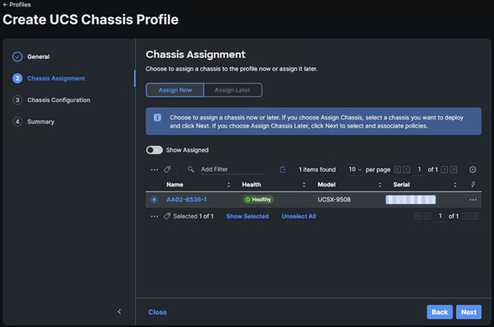
Step 9. In the Device Console, the fabric interconnect status should now be set to Claimed.
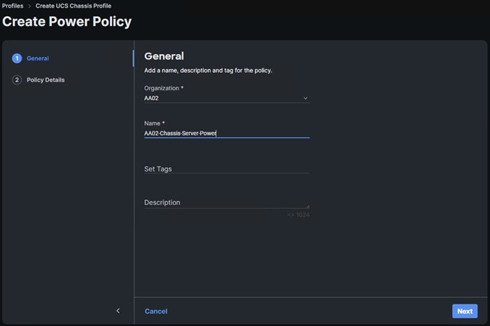
Procedure 7. Upgrade Fabric Interconnect Firmware using Cisco Intersight
If your Cisco UCS 6664 Fabric Interconnects are not already running firmware release 6.0(2.260045) (NX-OS version 10.5(1)I60(2b)), upgrade them to 6.0(2.260045) or later.
Step 1. Log into the Cisco Intersight portal.
Step 2. Select Operate > Fabric Interconnects.
Step 3. Click the ellipses “…” at the end of the row for either of the Fabric Interconnects and select Upgrade Firmware.
Step 4. Ensure both FIs are selected and click Next.
Step 5. Enable Advanced Mode using the toggle switch and uncheck Fabric Interconnect Traffic Evacuation.
Step 6. Select 6.0(2.260045) release or later from the list and click Next.
Step 7. Verify the information and click Upgrade to start the upgrade process. Click Upgrade.
Step 8. Watch the Request panel of the main Intersight screen as the system will ask for user permission before upgrading each FI. Click the Circle with Arrow and follow the prompts on screen to grant permission.
Step 9. Wait for both the FIs to successfully upgrade.
Procedure 8. Create VLAN Policy
Step 1. In Cisco Intersight select Configure > Policies. In the upper right corner click Create Policy.
Step 2. Select VLAN and click Start.
Step 3. Verify the correct organization is selected from the drop-down list (for example, AA02-Policy) and provide a name for the policy (for example, AA02-6664-VLAN). Ensure the UCS Domain Target Platform is selected. Add any necessary tags. Enter an optional Description and click Next.
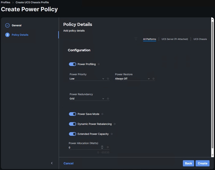
Step 4. Click Add VLANs.
Step 5. Provide a name (Native) and VLAN ID (2) for the native VLAN.
Step 6. Make sure Auto Allow On Uplinks is enabled.
Step 7. To create the required Multicast policy, under Multicast, click Select Policy.
Step 8. In the window on the right, click Create Policy to create a new Multicast Policy.
Step 9. Provide a Name for the Multicast Policy (for example, AA02-MCAST). Add any necessary tags. Enter an optional Description and click Next.
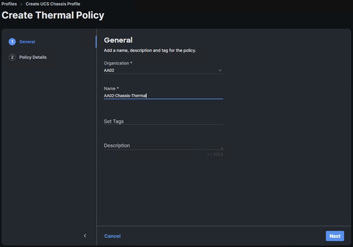
Step 10. Leave the default settings and click Create.
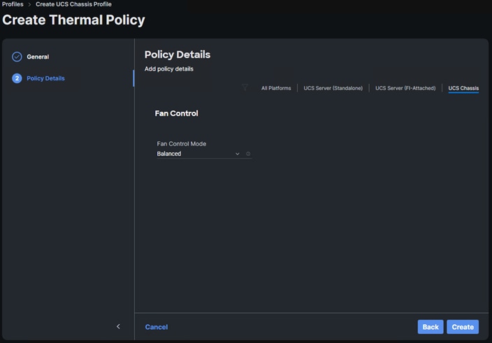
Step 11. Click Add to add the VLAN.
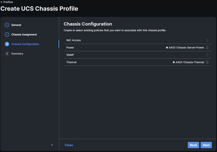
Step 12. Select Set Native VLAN ID and enter the VLAN number (for example, 2) under VLAN ID. Do not click Create.
Step 13. Add the OOB-MGMT VLAN by clicking Add VLANs and entering the OOB-MGMT VLAN name and VLAN ID (1020). To select the previously create Multicast policy, click Select Policy and use the radio button to select the Multicast policy. Click Select. Click Add.
Step 14. Click Create to finish creating the VLAN policy and associated VLANs.
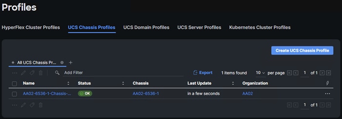
Procedure 9. Create VSAN Policy (FC/FCoE configuration only)
Step 1. In the upper right corner click Create Policy.
Step 2. Select VSAN and click Start.
Step 3. Verify the correct organization is selected from the drop-down list (for example, AA02-Policy) and provide a name for the policy (for example, AA02-6664-VSAN-A). Add any necessary tags. Enter an optional Description and click Next.
Note: A separate VSAN-Policy is created for each fabric interconnect.
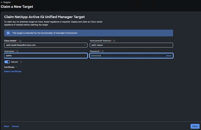
Step 4. Optional: enable Uplink Trunking.
Step 5. Click Add VSAN and provide a name (for example, VSAN-A), VSAN Scope (for example, Uplink) VSAN ID (for example, 101), and associated Fibre Channel over Ethernet (FCoE) VLAN ID (for example, 101) for SAN A. Click Add.
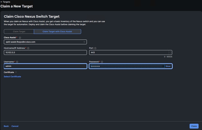
Step 6. Click Create to finish creating VSAN policy for fabric A.
Step 7. Click the ellipses to the right of the newly created VSAN-A policy and choose Clone.
Step 8. Adjust the Policy Name, Organization, Description, and Tags. Click Clone.
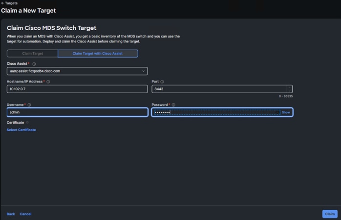
Step 9. Click the ellipses to the right of the newly created VSAN-B policy and choose Edit.
Step 10. Verify the General fields and click Next. Select the checkbox to the left of VSAN-A and click the trash can icon to delete the VSAN. Click Delete.
Step 11. Click Add VSAN and provide a name (for example, VSAN-B), VSAN Scope (for example, Uplink) VSAN ID (for example, 102), and associated Fibre Channel over Ethernet (FCoE) VLAN ID (for example, 102) for SAN B. Click Add.
Step 12. Click Save to complete editing the policy.
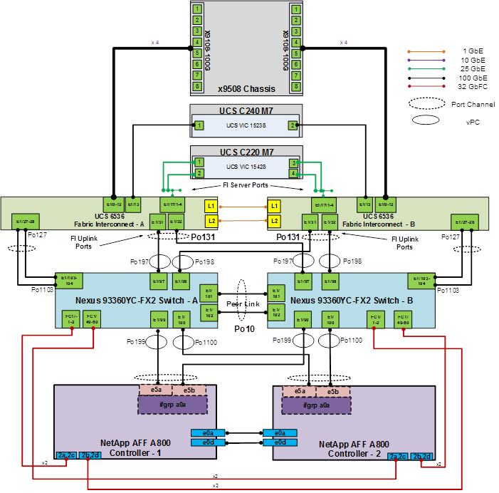
Procedure 10. Create Port Policy
Step 1. In the upper right corner click Create Policy.
Step 2. Select Port and click Start.
Step 3. Verify the correct organization is selected from the drop-down list (for example, AA02-Policy) and provide a name for the policy (for example, AA02-6664-Port-A). Leave Target Platform set to Fabric Interconnect. Select your Fabric Interconnect Model (for example, UCS-FI-6664). Add any necessary tags. Enter an optional Description and click Next.
Note: Use two separate port policies for the fabric interconnects. Using separate policies provide flexibility when port configuration (port numbers or speed) differs between the two FIs. When configuring Fibre Channel, two port policies are required because each fabric interconnect uses a unique Fibre Channel VSAN ID.
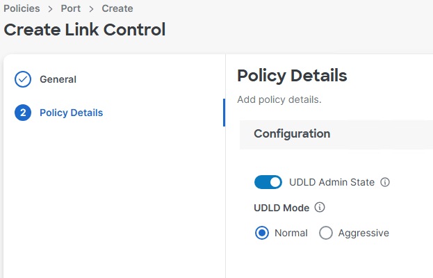
Step 4. If configuring FC, move the slider to set up unified ports. In this deployment with the 6664 FI, FC ports are selected in groups of 4 up to 16 ports. Please see the Cisco UCS documentation for FC port configuration in different FIs. Click Next.
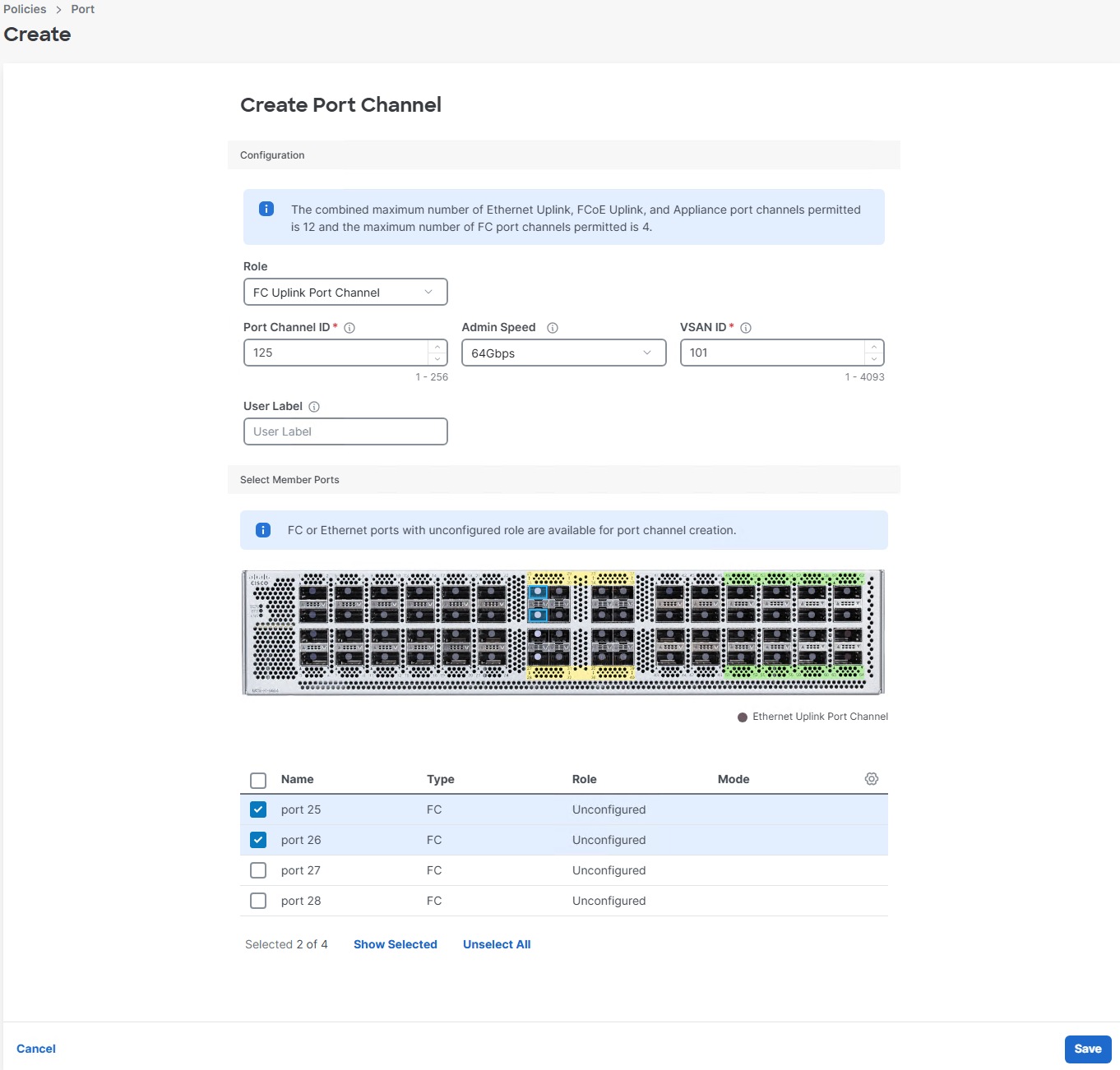
Step 5. In this deployment, the 6664 FI does not support breakout ports and that configuration section is greyed out and skipped. If you have a different FI and any ethernet ports need to be configured as breakouts, either 4x25G or 4x10G, for connecting Cisco UCS C-Series servers or a Cisco UCS 5108 chassis, configure them here. Click Next.
Step 6. From the list, check the box next to any ports that need to be configured as server ports, including ports connected to chassis or Cisco UCS C-Series servers. Ports can also be selected on the graphic. When all ports are selected, click Configure. Breakout and non-breakout ports cannot be configured together. If you need to configure breakout and non-breakout ports, do this configuration in two steps.
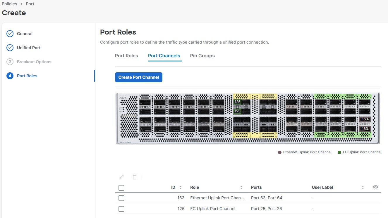
Step 7. From the drop-down list, select Server as the role. Also, unless you are using a Cisco Nexus 93360YC-FX2 as a FEX, leave Auto Negotiation enabled. If you need to do manual chassis or Cisco UCS C-Series Servers, enable Manual Chassis/Server Numbering. Click Save.
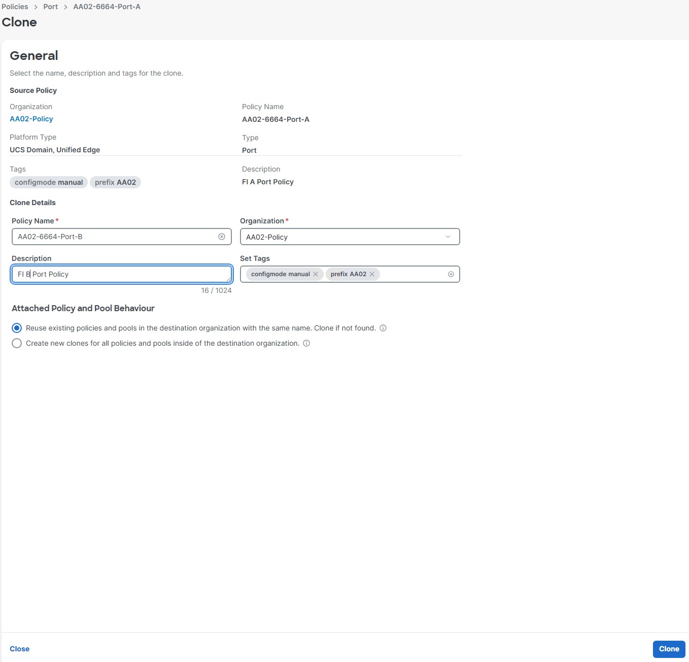
Step 8. Configure the Ethernet uplink port channel by selecting the Port Channels tab in the main pane and then clicking Create Port Channel.
Step 9. Select Ethernet Uplink Port Channel as the Role, provide a port-channel ID (for example, 163), and select a value for Admin Speed FEC from the drop-down lists (for example, Auto).
Note: You can create the Ethernet Network Group, Flow Control, and Link Aggregation policies for defining a disjoint Layer-2 domain or fine tune port-channel parameters. These policies were not used in this deployment and system default values were utilized.
Step 10. Under Link Control, click Select Policy then click Create Policy.
Step 11. Verify the correct organization is selected from the drop-down list (for example, AA02) and provide a name for the policy (for example, AA02-UDLD-Link-Control). Add any necessary tags. Enter an optional Description and click Next.
Step 12. Leave the default values selected and click Create.
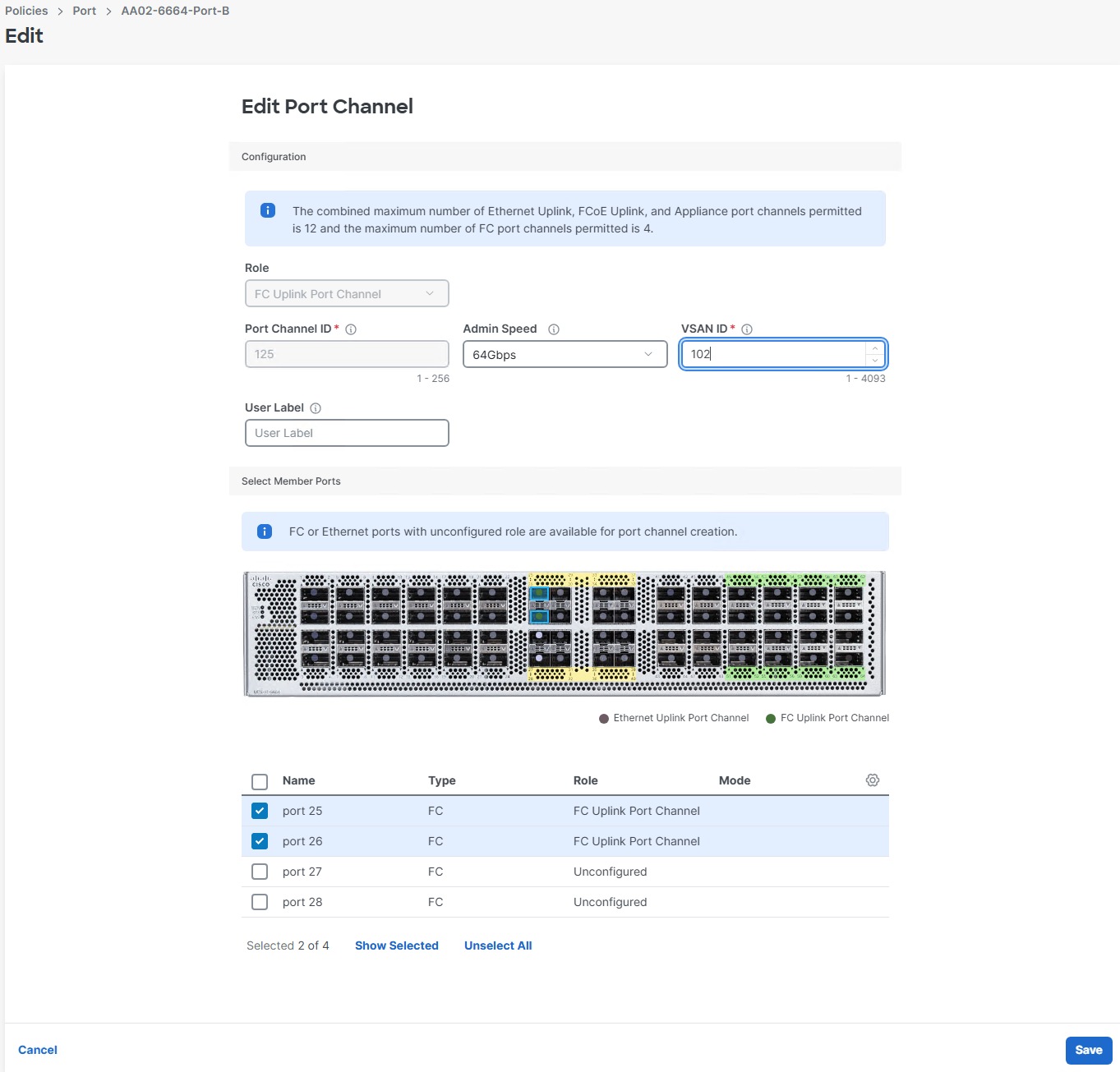
Step 13. Scroll down and select the uplink ports from the list of available ports (for example, port 63 and 64)
Step 14. Click Save.
Note: FC uplink port channels are only needed when configuring FC SAN and can be skipped for IP-only storage access.
Step 15. Configure a Fibre Channel Port Channel by clicking Create Port Channel.
Step 16. From the Role drop-down list, select FC Uplink Port Channel.
Step 17. Provide a port-channel ID (for example, 125), select a value for Admin Speed (for example, 64Gbps), and provide a VSAN ID (for example, 101).
Step 18. Select member ports (for example, 25 and 26).
Step 19. Click Save.
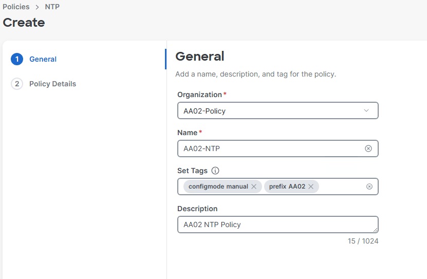
Step 20. Verify the port-channel IDs and ports after both the Ethernet uplink port channel and the Fibre Channel uplink port channel (if configuring FC) have been created.
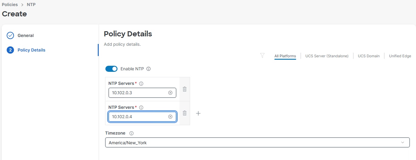
Step 21. Click Save to create the port policy for Fabric Interconnect A.
Step 22. Since the port usage between the two FIs is the same in this configuration, we can clone FI A port policy for FI B and adjust. Click the ellipses to the right of the FI A port policy and select Clone.
Step 23. Adjust the Policy Name, Organization, Description, and Tags. Click Clone.
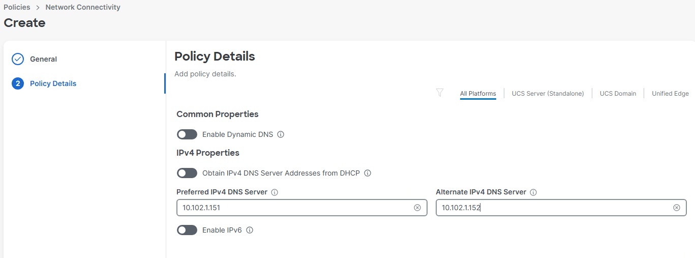
Step 24. Click the ellipses to the right of the newly cloned FI B port policy and select Edit.
Step 25. Verify the General fields and click Next.
Step 26. Verify the Unified Port settings and click Next.
Step 27. Verify the Server Port Roles and click the Port Channels tab.
Step 28. If configuring FC, select the checkbox next to the FC Uplink Port Channel and click the pencil icon to edit. Adjust the VSAN ID and click Save.
Note: The same port channel IDs can be used in both FIs.
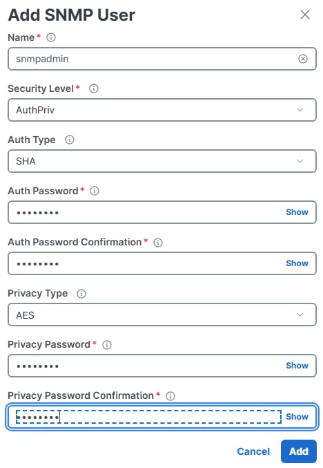
Step 29. Click Save to save the policy.
Procedure 11. Configure NTP Policy
Step 1. In the upper right corner click Create Policy.
Step 2. Select NTP and click Start.
Step 3. Verify the correct organization is selected from the drop-down list (for example, AA02-Policy) and provide a name for the policy (for example, AA02-NTP). Add any necessary tags. Enter an optional Description and click Next.
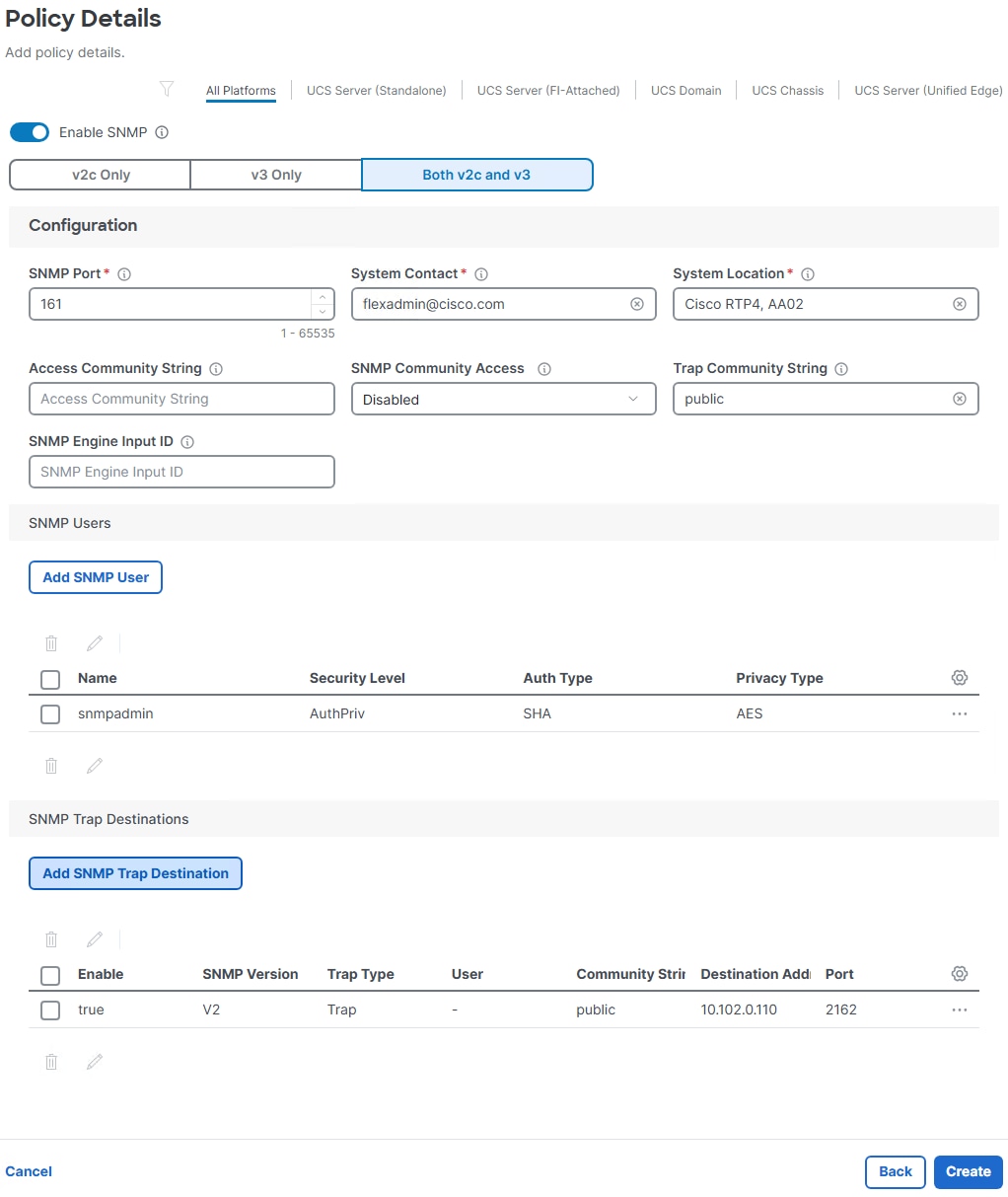
Step 4. Enable NTP, provide the first NTP server IP address, and select the time zone from the drop-down list.
Step 5. Add a second NTP server by clicking + next to the first NTP server IP address
Note: The NTP server IP addresses should be Nexus switch management IPs. NTP distribution was configured in the Cisco Nexus switches.
Step 6. Click Create.
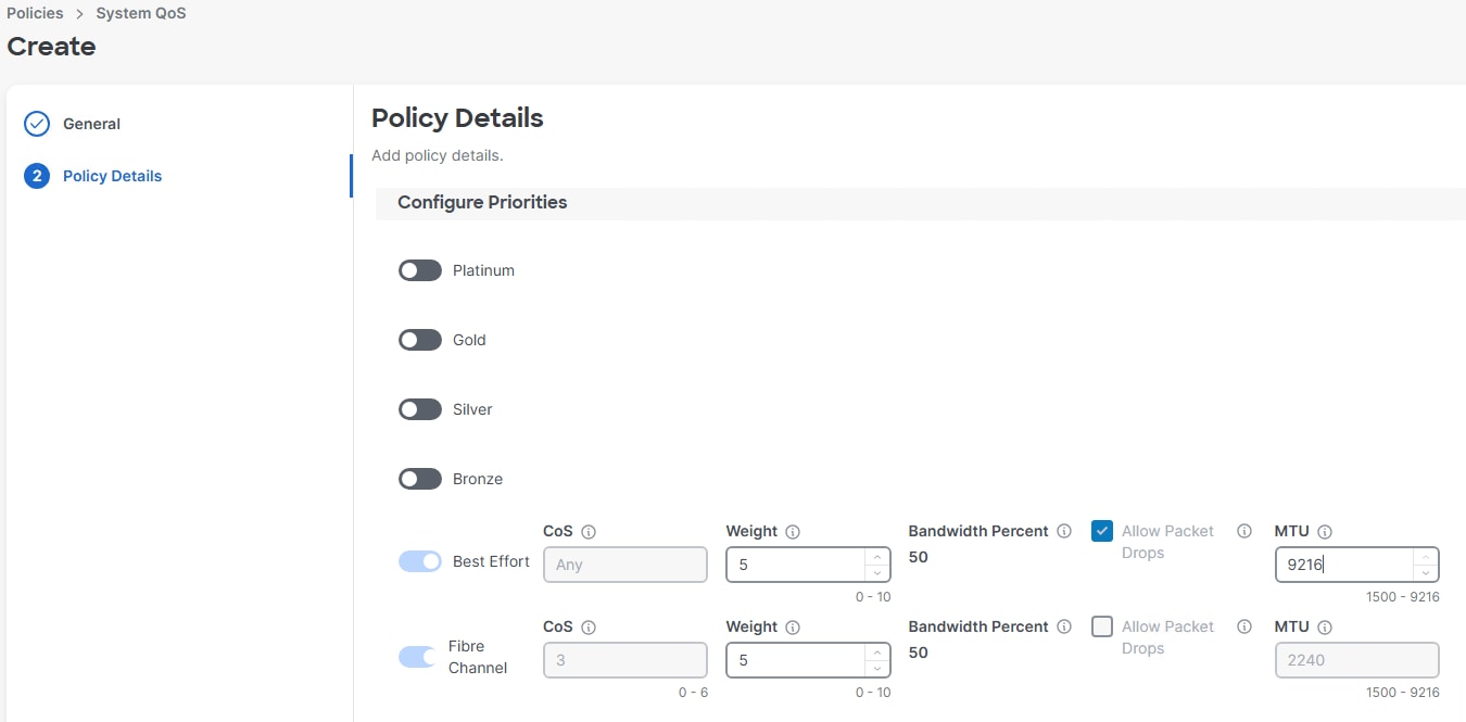
Procedure 12. Configure Network Connectivity (DNS Server) Policy
Step 1. In the upper right corner click Create Policy.
Step 2. Select Network Connectivity and click Start.
Step 3. Verify the correct organization is selected from the drop-down list (for example, AA02-Policy) and provide a name for the policy (for example, AA02-Network-Connectivity). Add any necessary tags. Enter an optional Description and click Next.
Step 4. Provide DNS server IP addresses for Cisco UCS (for example, 10.102.1.151 and 10.102.1.152).
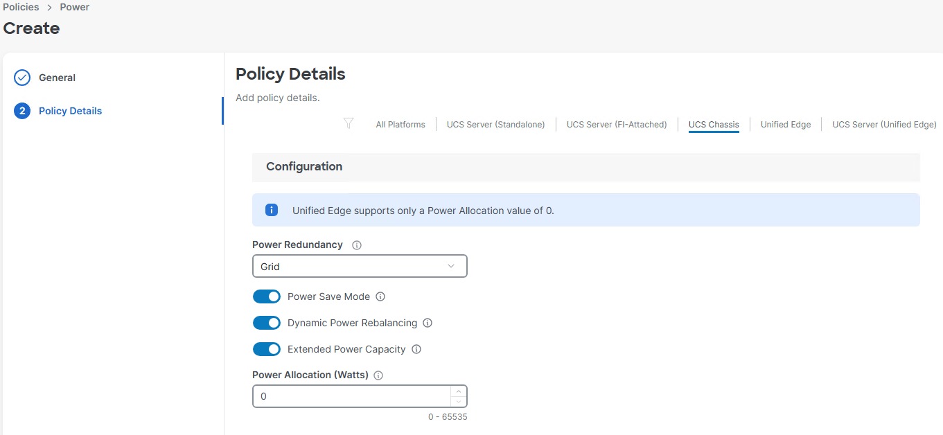
Step 5. Click Create.
Procedure 13. Configure SNMP Policy
Step 1. In the upper right corner click Create Policy.
Step 2. Select SNMP and click Start.
Step 3. Verify the correct organization is selected from the drop-down list (for example, AA02-Policy) and provide a name for the policy (for example, AA02-SNMP). Add any necessary tags. Enter an optional Description and click Next.
Step 4. Provide a System Contact email address, a System Location, and optional Community Strings.
Step 5. Under SNMP Users, click Add SNMP User.
Step 6. This user id will be used for Cisco Nexus Dashboard SAN to query the UCS Fabric Interconnects. Fill in a user name (for example, snmpadmin), Auth Type SHA, an Auth Password with confirmation, Privacy Type AES, and a Privacy Password with confirmation. Click Add.
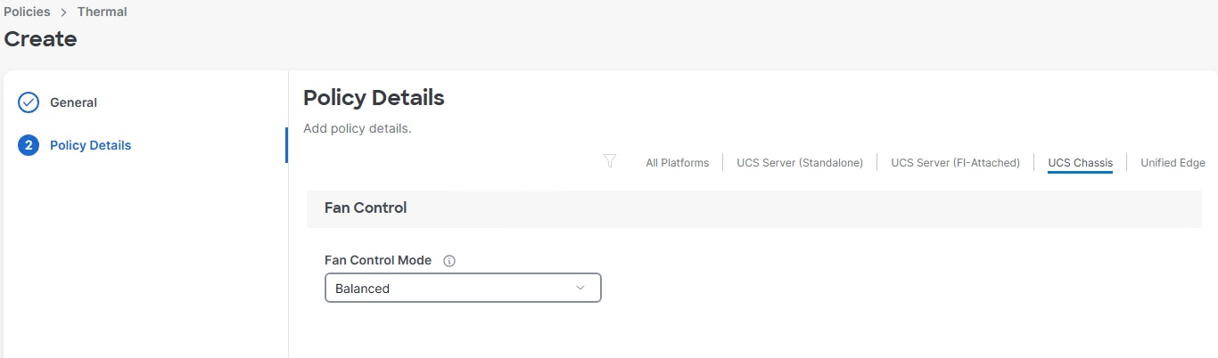
Step 7. Optional: Add an SNMP Trap Destination (for example, the Nexus Dashboard SAN or LAN IP Address). If the SNMP Trap Destination is V2, you must add Trap Community String.
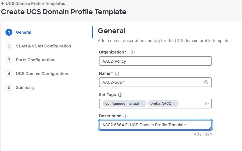
Step 8. Click Create.
Procedure 14. Configure System QoS Policy
Step 1. In the upper right corner click Create Policy.
Step 2. Select System QoS and click Start.
Step 3. Verify the correct organization is selected from the drop-down list (for example, AA02-Policy) and provide a name for the policy (for example, AA02-System-QoS). Set the Target Platform to UCS Domain. Add any necessary tags. Enter an optional Description and click Next.
Step 4. Change the MTU for the Best Effort class to 9216.
Step 5. Keep the default selections or change the parameters if necessary.
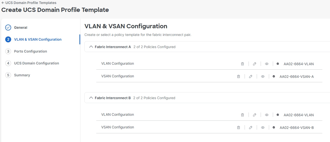
Step 6. Click Create.
Procedure 15. Create a Cisco UCS Chassis Power Policy
Step 1. In the upper right corner click Create Policy.
Step 2. Select Power and click Start.
Step 3. Verify the correct organization is selected from the drop-down list (for example, AA02-Policy) and provide a name for the policy (for example, AA02-X9508-Chassis-Power). Add any necessary tags. Enter an optional Description and click Next.
Step 4. Select the UCS Chassis platform. Leave all other values at the default settings or configure according to your local power policies. Click Create.
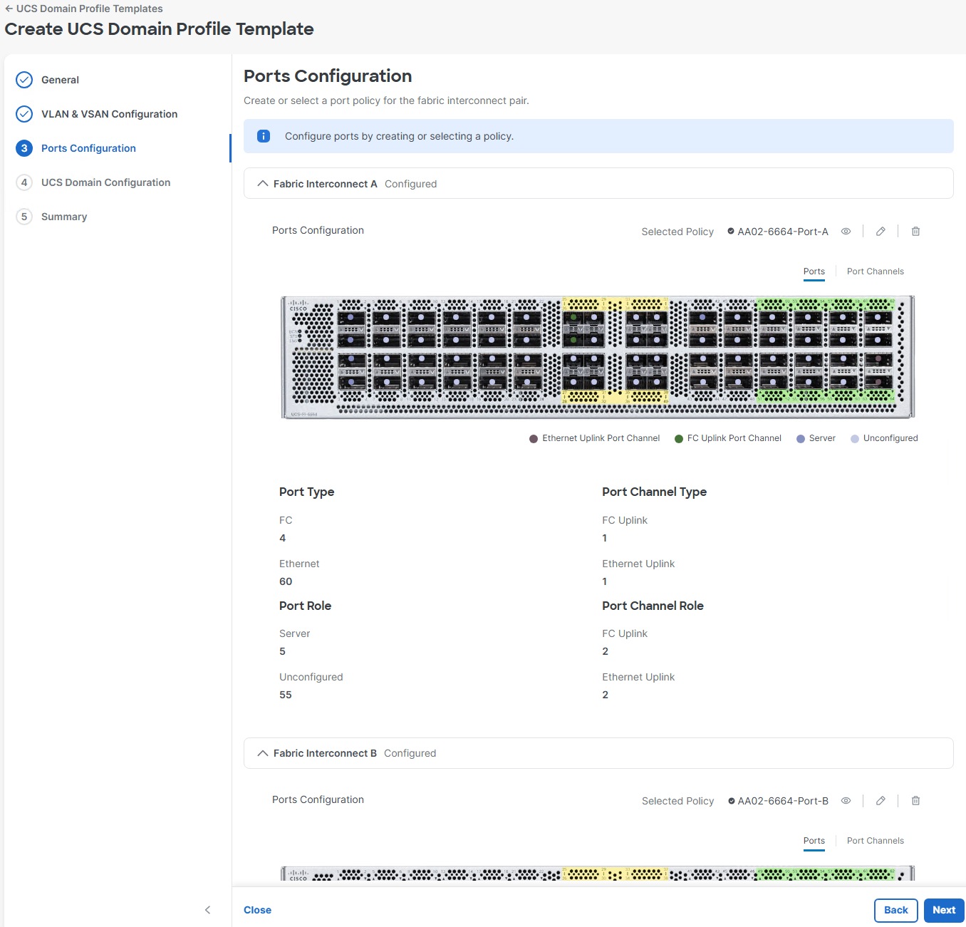
Procedure 16. Create a Cisco UCS Chassis Thermal Policy
Step 1. In the upper right corner click Create Policy.
Step 2. Select Thermal and click Start.
Step 3. Verify the correct organization is selected from the drop-down list (for example, AA02-Policy) and provide a name for the policy (for example, AA02-X9508-Chassis-Power). Add any necessary tags. Enter an optional Description and click Next.
Step 4. Select the UCS Chassis platform. Leave Fan Control Mode at the default setting or configure according to your local policies. Click Create.
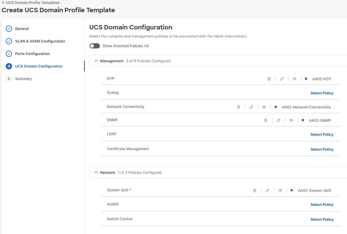
Procedure 17. Create a Cisco UCS Domain Profile Template and Profile
Note: A Cisco UCS domain profile template can be used to create a Cisco UCS domain profile, which configures a fabric interconnect pair through reusable policies, allows configuration of the ports and port channels, and configures the VLANs and VSANs in the network. It defines the characteristics of and configured ports on fabric interconnects. The domain-related policies can be attached to the profile either at the time of creation or later. One Cisco UCS domain profile can be assigned to one fabric interconnect domain.
Step 1. Select Configure > Templates and then select the UCS Domain Profile Templates tab.
Step 2. Click Create UCS Domain Profile Template.
Step 3. Verify the correct organization is selected from the drop-down list (for example, AA02-Policy) and provide a name for the template (for example, AA02-6664). Set the Target Platform to UCS Domain. Add any necessary tags. Enter an optional Description and click Next.
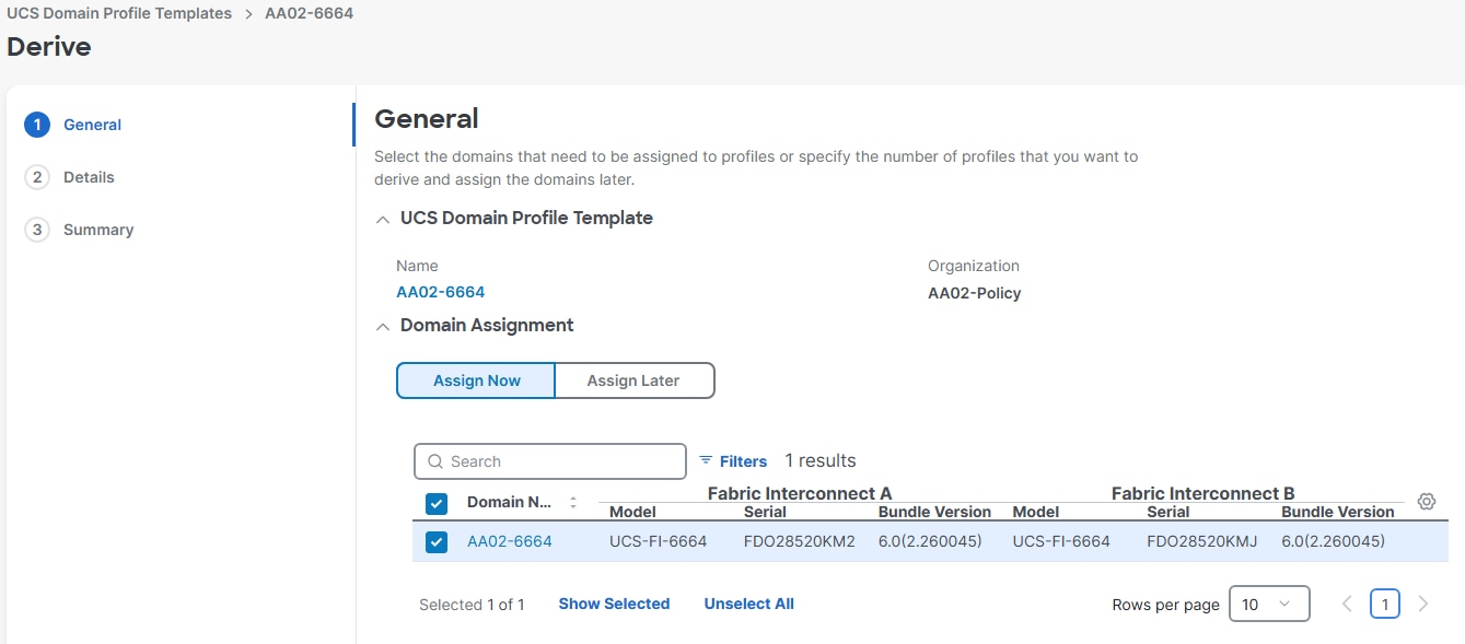
Step 4. Using the Select Policy links, select the VLAN policy for both FIs and select the VSAN-A and VSAN-B policies with the corresponding FIs. Click Next.
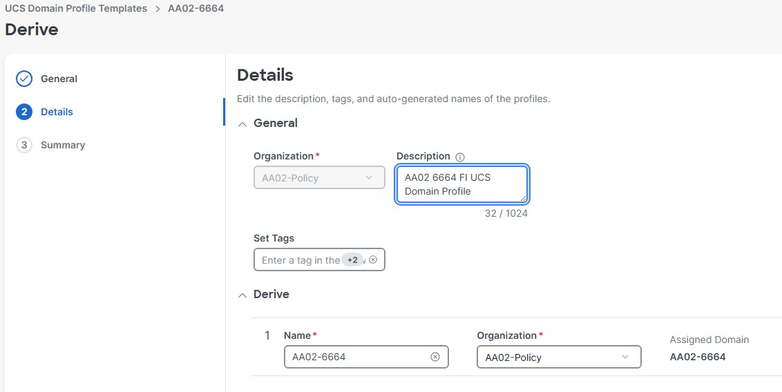
Step 5. Using the Select Policy links, select the Port-A and Port-B policies with the corresponding FIs. Click Next.
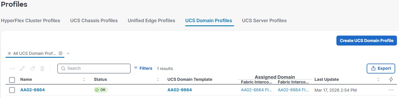
Step 6. Using the Select Policy links, select the NTP, Network Connectivity, SNMP, and System QoS policies. Click Next.

Step 7. Review each of the tabs and the FI info and click Derive Profiles.
Step 8. To assign the derived profile to the FIs, select the checkbox to the left of the Domain Name and click Next.
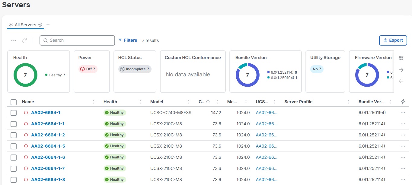
Step 9. Adjust the Details according to your environment setup considering whether this will be the only set of FIs attached to this template. Click Next.
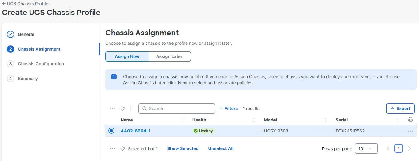
Step 10. Review the Summary info and click Derive.
Procedure 18. Deploy the UCS Domain Profile
Step 1. Select the Configure > Profiles.
Step 2. Click the ellipses to the right of the UCS Domain Profile and select Deploy. Click Deploy.
Note: The system will take some time to validate and configure the settings on the FIs. If FC is configured, the FIs will reboot. Log into the FIs’ serial console servers to see when the FIs have finished configuration and are successfully rebooted.
Procedure 19. Verify Cisco UCS Domain Profile Deployment
When the Cisco UCS domain profile has been successfully deployed, the Cisco UCS chassis, blades, and Cisco UCS C-Series servers should be successfully discovered.
Note: It takes a while to discover the blades and rackmounts for the first time. Watch the number of outstanding requests in Cisco Intersight.
Step 1. Under Configure > Profiles > UCS Domain Profiles, verify that the domain profile has been successfully deployed.
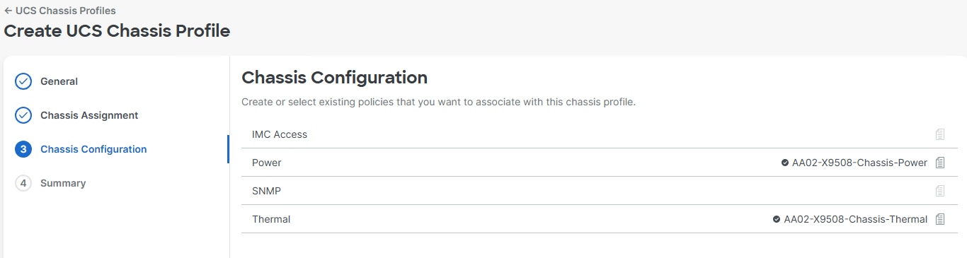
Step 2. Verify that the chassis (either UCSX-9508 or UCS 5108 chassis) has been discovered and is visible under Operate > Chassis.
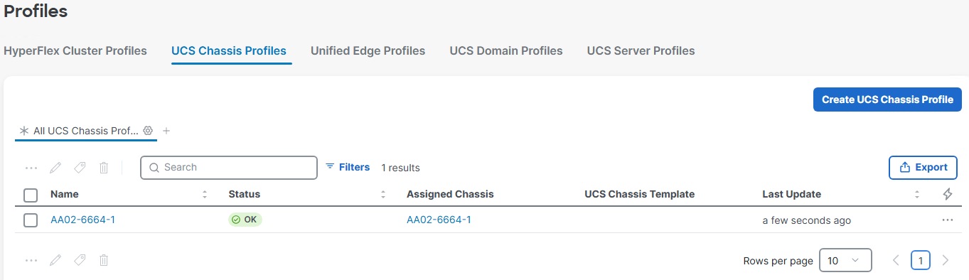
Step 3. Verify that the servers have been successfully discovered and are visible under Operate > Servers.
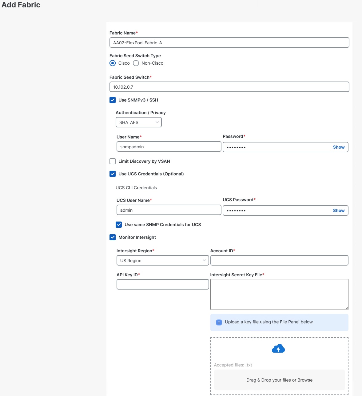
Procedure 20. Configure a Cisco UCS Chassis Profile
Note: A Cisco UCS chassis profile configures either a UCS X9508 or UCS 5108 chassis through reusable policies. It defines the characteristics of power distribution and fan configuration in the chassis. One Cisco UCS chassis profile can be assigned to one chassis.
Step 1. Select Configure > Profiles > UCS Chassis Profiles.
Step 2. Click Create UCS Chassis Profile.
Step 3. Click Start.
Step 4. Verify the correct organization is selected from the drop-down list (for example, AA02) and provide a name for the profile (for example, AA02-6664-1). Add any necessary tags. Enter an optional Description and click Next.
Note: Note that we are placing this profile in the organization that is attached to the resource group instead of in the organization with the policies.
Step 5. Use the radio button to select the chassis you want to assign this profile to and click Next.
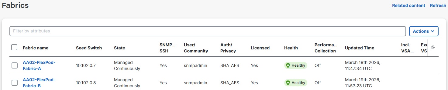
Step 6. Using the Select Policy links, select the Power and Thermal policies from the Shared Policies. Click Next.
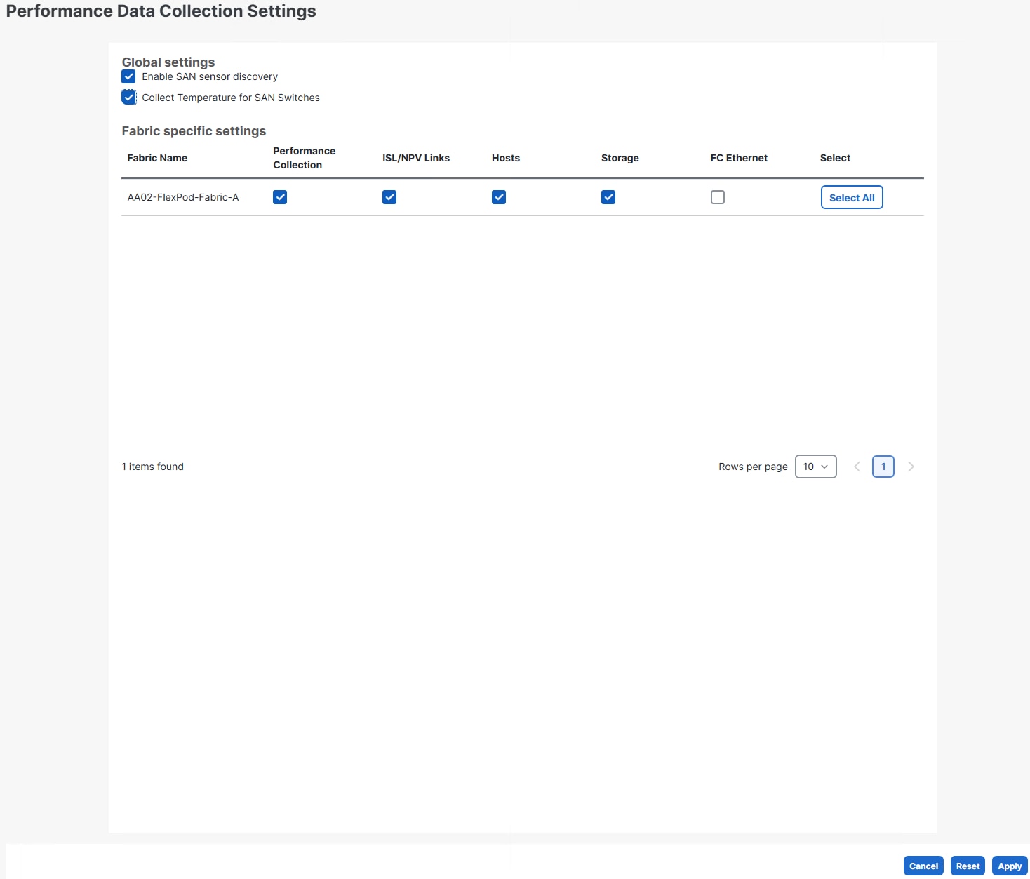
Step 7. Review the summary info and click Deploy. On the popup, click Deploy.
Step 8. When the profile is successfully deployed, the Status will show OK.

Note: This set of procedures can be used to create profiles for additional chassis. In these additional chassis profiles, the power and thermal policies can be reused as needed.
Procedure 21. Upgrade Chassis Firmware
Step 1. In Cisco Intersight, select Operate > Chassis.
Step 2. Click the ellipses to the right of the chassis that you want to upgrade and select Upgrade Firmware.
Step 3. Click Next.
Step 4. Select the 6.0(2.260042) or later version and click Next.
Step 5. Click Upgrade. On the popup, click Upgrade.
Procedure 22. Upgrade X580p Firmware
If you have one or more X580p GPU Nodes, upgrade the firmware to the latest release.
Step 1. In Cisco Intersight, select Operate > Chassis.
Step 2. Click on a chassis name of a chassis with an X580p to get to the chassis detailed view. Click the Inventory tab and select PCIe Nodes.
Step 3. If an X580p is listed and its firmware version is less than 6.0(2.260043), click ellipses to the right of the X580p and select Upgrade Firmware.
Step 4. Click Next.
Step 5. Select the 6.0(2.260043) or later bundle and click Next.
Step 6. Click Upgrade. On the popup, click Upgrade.
Step 7. Optionally, upgrade server firmware or wait and upgrade automatically with a firmware policy.
This chapter contains the following:
● Cisco Nexus Dashboard SAN Setup
● Cisco Nexus Dashboard SAN Fabric Setup
This chapter explains how to configure the Cisco MDS 9000s for use in a FlexPod environment. The configuration covered in this section is only needed when configuring Fibre Channel and FC-NVMe storage access.
Note: If FC connectivity is not required in the FlexPod deployment, this section can be skipped.
Follow the physical connectivity guidelines for FlexPod as explained in Physical Topology section.
The following procedures describe how to configure the Cisco MDS switches for use in a base FlexPod environment. This procedure assumes you are using the Cisco MDS 9124V with NX-OS 9.4(3b).
Procedure 1. Set up Cisco MDS 9124V A and 9124V B
Note: On initial boot and connection to the serial or console port of the switch, the NX-OS setup should automatically start and attempt to enter Power on Auto Provisioning. Enter y to get to the System Admin Account Setup.
Step 1. Configure the switch using the command line:
---- System Admin Account Setup ----
Do you want to enforce secure password standard (yes/no) [y]: Enter
Enter the password for "admin": <password>
Confirm the password for "admin": <password>
Would you like to enter the basic configuration dialog (yes/no): yes
Create another login account (yes/no) [n]: Enter
Configure read-only SNMP community string (yes/no) [n]: Enter
Configure read-write SNMP community string (yes/no) [n]: Enter
Enter the switch name : <mds-hostname>
Continue with Out-of-band (mgmt0) management configuration? (yes/no) [y]: Enter
Mgmt0 IPv4 address : <mds-mgmt0-ip>
Mgmt0 IPv4 netmask : <mds-mgmt0-netmask>
Configure the default gateway? (yes/no) [y]: Enter
IPv4 address of the default gateway : <mds-mgmt0-gw>
Configure advanced IP options? (yes/no) [n]: Enter
Enable the ssh service? (yes/no) [y]: Enter
Type of ssh key you would like to generate (dsa/rsa) [rsa]: Enter
Number of rsa key bits <1024-2048> [1024]: 2048
Enable the telnet service? (yes/no) [n]: Enter
Configure congestion/no_credit drop for fc interfaces? (yes/no) [y]: Enter
Enter the type of drop to configure congestion/no_credit drop? (con/no) [c]: Enter
Enter milliseconds in multiples of 10 for congestion-drop for logical-type edge
in range (<200-500>/default), where default is 500. [d]: Enter
Enable the http-server? (yes/no) [y]: Enter
Configure clock? (yes/no) [n]: Enter
Configure timezone? (yes/no) [n]: Enter
Configure summertime? (yes/no) [n]: Enter
Configure the ntp server? (yes/no) [n]: Enter
Configure default switchport interface state (shut/noshut) [shut]: Enter
Configure default switchport trunk mode (on/off/auto) [on]: auto
Configure default switchport port mode F (yes/no) [n]: y
Configure default zone policy (permit/deny) [deny]: Enter
Enable full zoneset distribution? (yes/no) [n]: y
Configure default zone mode (basic/enhanced) [basic]: Enter
Step 2. Review the configuration.
Would you like to edit the configuration? (yes/no) [n]: Enter
Use this configuration and save it? (yes/no) [y]: Enter
Procedure 2. FlexPod Cisco MDS Switch Manual Configuration
Step 1. Connect to both Cisco MDS switches with the admin user using ssh.
Step 2. Configure features on both MDS switches.
configure terminal
feature nxapi
feature npiv
feature fport-channel-trunk
Step 3. Configure an SNMP V3 user, DNS servers, NTP servers and local time configuration. It is important to configure the local time so that logging time alignment and any backup schedules are correct. For more information on configuring the timezone and daylight savings time or summertime, see the Cisco MDS 9000 Series Fundamentals Configuration Guide, Release 9.x.
snmp-server user snmpadmin network-admin auth sha <password> priv aes-128 <password>
ip name-server <dns-server-1> <dns-server-2>
ntp server <nexus-A-mgmt0-ip>
ntp server <nexus-B-mgmt0-ip>
clock timezone <timezone> <hour-offset> <minute-offset>
clock summer-time <timezone> <start-week> <start-day> <start-month> <start-time> <end-week> <end-day> <end-month> <end-time> <offset-minutes>
copy running-config startup-config
Sample clock commands for the United States Eastern timezone are:
clock timezone EST -5 0
clock summer-time EDT 2 Sunday March 02:00 1 Sunday November 02:00 60
copy running-config startup-config
Step 4. Configure individual ports on Cisco MDS A.
interface fc1/1
switchport description <st-clustername>-01:8a
switchport speed 64000
switchport trunk mode off
no shutdown
exit
interface fc1/2
switchport description <st-clustername>-02:8a
switchport speed 64000
switchport trunk mode off
no shutdown
exit
interface fc1/5
switchport description <ucs-domainname>-A:fc1/25
channel-group 15
no shutdown
exit
interface fc1/6
switchport description <ucs-domainname>-A:fc1/26
channel-group 15
no shutdown
exit
interface port-channel15
channel mode active
switchport trunk allowed vsan <vsan-a-id>
y
switchport description <ucs-clustername>-A
switchport speed 64000
no shutdown
exit
Note: If VSAN trunking is not being used between the Cisco UCS Fabric Interconnects and the MDS switches, do not enter “switchport trunk allowed vsan <vsan-a-id>” for interface port-channel15. Also, the default setting of the switchport trunk mode auto is being used for the port channel.
Step 5. Configure individual ports on Cisco MDS B:
interface fc1/1
switchport description <st-clustername>-01:8b
switchport speed 64000
switchport trunk mode off
no shutdown
exit
interface fc1/2
switchport description <st-clustername>-02:8b
switchport speed 64000
switchport trunk mode off
no shutdown
exit
interface fc1/5
switchport description <ucs-domainname>-B:fc1/25
channel-group 15
no shutdown
exit
interface fc1/6
switchport description <ucs-domainname>-B:fc1/26
channel-group 15
no shutdown
exit
interface port-channel15
channel mode active
switchport trunk allowed vsan <vsan-b-id>
y
switchport description <ucs-clustername>-B
switchport speed 64000
no shutdown
exit
Note: If VSAN trunking is not being used between the Cisco UCS Fabric Interconnects and the MDS switches, do not enter “switchport trunk allowed vsan <vsan-B-id>” for interface port-channel15. Also, the default setting of the switchport trunk mode auto is being used for the port channel.
Step 6. Create and configure the Fabric-A VSAN:
vsan database
vsan <vsan-a-id>
vsan <vsan-a-id> name FlexPod-Fabric-A
exit
zone smart-zoning enable vsan <vsan-a-id>
vsan database
vsan <vsan-a-id> interface fc1/1
y
vsan <vsan-a-id> interface fc1/2
y
vsan <vsan-a-id> interface port-channel15
exit
copy r s
Step 7. Create and configure the Fabric-B VSAN:
vsan database
vsan <vsan-b-id>
vsan <vsan-b-id> name FlexPod-Fabric-B
exit
zone smart-zoning enable vsan <vsan-b-id>
vsan database
vsan <vsan-b-id> interface fc1/1
y
vsan <vsan-b-id> interface fc1/2
y
vsan <vsan-b-id> interface port-channel15
exit
copy r s
Step 8. Smart licensing should be setup in the MDS switches. For more information see: Cisco MDS 9000 Series Licensing Guide, Release 9.x.
Cisco Nexus Dashboard SAN Setup
In this lab configuration, Cisco Nexus Dashboard is used to monitor and configure the SAN fabrics. Nexus Dashboard is available in both physical and virtual form factors. In this lab configuration, one Nexus Dashboard virtual app node was installed into a cluster. Please see Nexus Dashboard Capacity Planning and Cisco Nexus Dashboard Data Sheet to determine the form factor and cluster size for your deployment. Then install Nexus Dashboard SAN using Cisco Nexus Dashboard Deployment and Upgrade Guide, Release 4.2.x.
Cisco Nexus Dashboard SAN Fabric Setup
Two SAN Fabrics (A and B) will be setup in Nexus Dashboard. Also, performance monitoring and optional SAN Analytics will be setup.
Procedure 1. Set up Cisco Nexus Dashboard SAN Fabric
Step 1. Use a web browser to navigate to the management IP of any node in the Nexus Dashboard cluster. Log in using the admin account.
Step 2. Select Manage > Fabrics.
Step 3. From the Actions drop-down list, choose Add Fabric.
Step 4. For Fabric Name, input something to indicate FlexPod-Fabric-A. Leave the Fabric Seed Type set to Cisco. For Fabric Seed Switch, input the IP address of MDS switch A. Leave Use SNMPv3 / SSH checked. For Authentication / Privacy, select SHA_AES. For User Name input snmpadmin and for Password input the corresponding password. Check Use UCS Credentials and input admin for UCS User Name and the corresponding password. Check Monitor Intersight.
Step 5. Using a different browser window, log into Cisco Intersight and select this FlexPod’s account. Select System > Account Details. Copy the Account ID to Account ID in the Nexus Dashboard window. Back in Intersight, select Settings > API SETTINGS > Keys. Click Generate API Key. For Description, input Nexus Dashboard SAN Intersight Monitor. Leave schema version 3 selected. For Expiration Time, select a future date and time (the default maximum expiration time is 6 months out). Click Generate. Click the download icon to save the Secret Key to a file on your workstation (you will need this for the other fabric). Copy the API Key ID to API Key ID in the Nexus Dashboard window. In the Nexus Dashboard window, upload the Secret Key File from your workstation. Back in Intersight, select I have downloaded the Secret Key and click Close.
Step 6. From in Nexus Dashboard SAN, click Add. On Success, click Ok.
Note: In the screenshot below, the Intersight API Key details were intentionally left out.
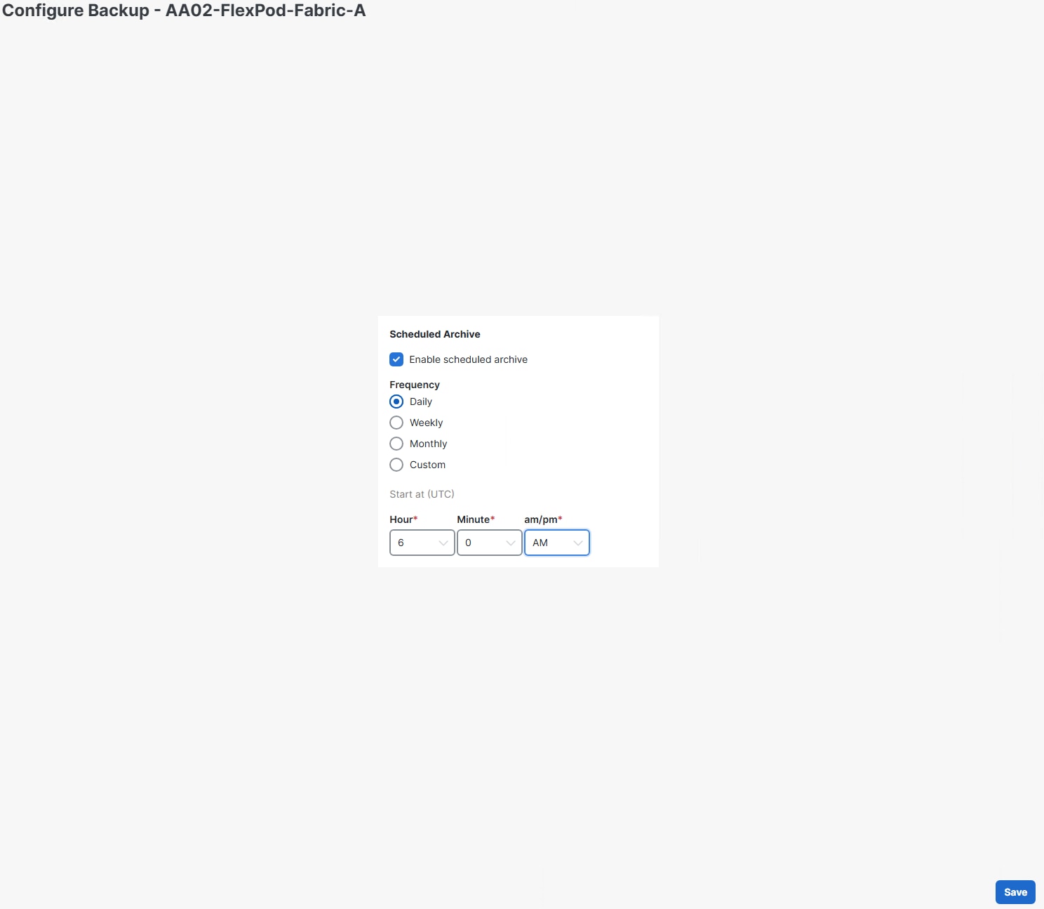
Step 7. Repeat Steps 3-6 to add FlexPod-Fabric-B to Nexus Dashboard SAN with the one exception being you will query the existing API Key ID from Intersight instead of creating one.
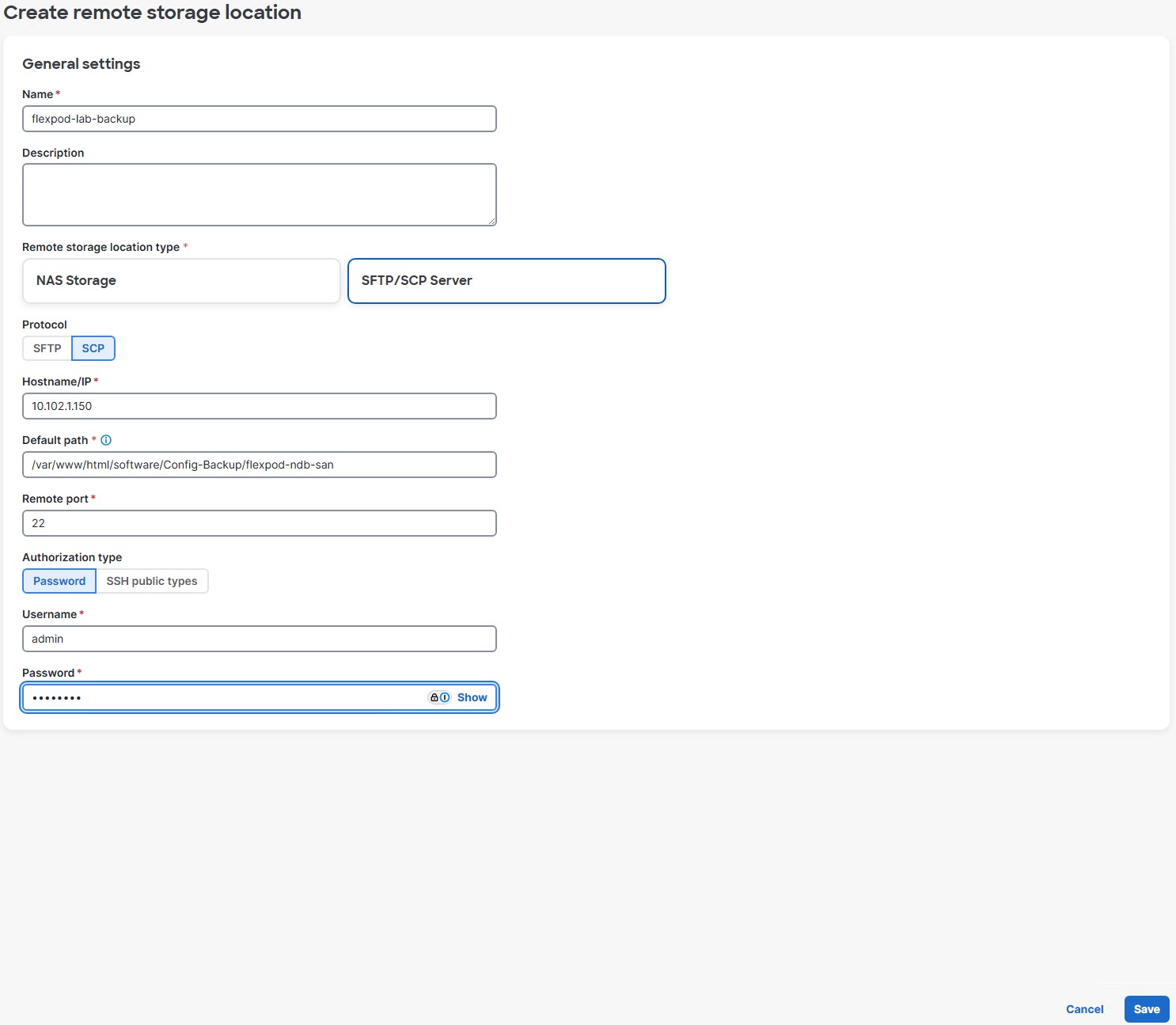
Step 8. Configure Performance Collection on FlexPod-Fabric-A by selecting the checkbox to the left of FlexPod-Fabric-A. From the Actions drop-down list, select Configure Performance. Select Enable SAN sensor discovery and Collect Temperature for SAN Switches. Click Apply. On the Confirmation popup, click Confirm.
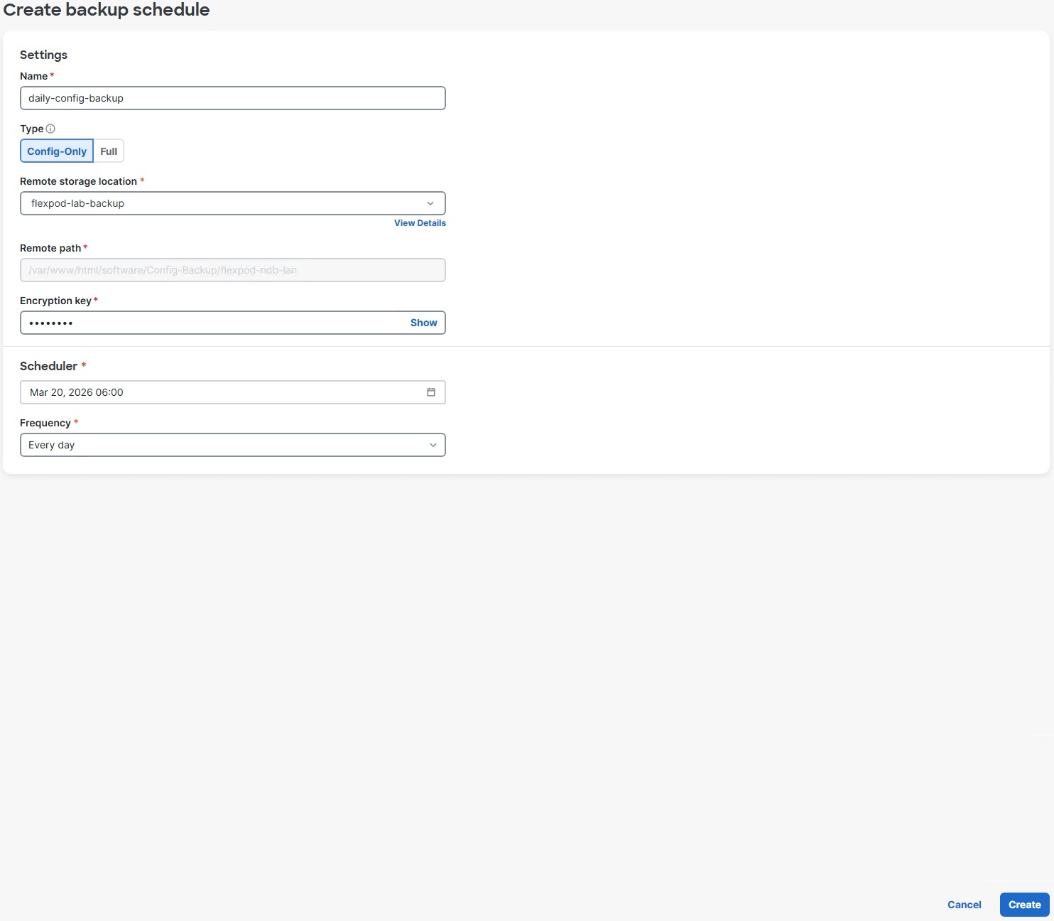
Step 9. Repeat the previous step to configure Performance Collection on FlexPod-Fabric-B.
Step 10. Enable the Nexus Dashboard SAN Web Device Manager feature by selecting Admin > System Settings > Feature Management. Select the checkbox to the left of SAN Web Device Manager and click Apply.
Step 11. Select Manage > Fabrics. Click a fabric’s text link to get a detailed popup. Click the ![]() popout icon to go to the fabric details window. Select the Switches tab. Click on the text link for an MDS switch to get a detailed popup. Click the popout icon to go to the switch details window. Select the Device Manager tab. You can log into the switch with the snmpadmin user id and password and SHA-AES Auth-Privacy. You can then use the Device Manager to query and configure the switch.
popout icon to go to the fabric details window. Select the Switches tab. Click on the text link for an MDS switch to get a detailed popup. Click the popout icon to go to the switch details window. Select the Device Manager tab. You can log into the switch with the snmpadmin user id and password and SHA-AES Auth-Privacy. You can then use the Device Manager to query and configure the switch.
Note: Device Manager only works with MDS and Nexus switches.
Step 12. Configure MDS configuration backup on a schedule by selecting Manage > Fabrics. Select the checkbox to the left of a fabric and use the Actions drop-down list to select Configure Backup.
Step 13. Select Enable scheduled archive. Select a Frequency and then select time and day in UTC time. Click Save. Click OK.
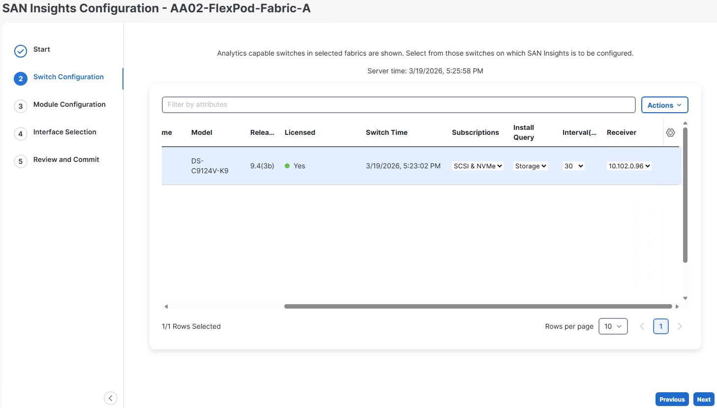
Step 14. Configure scheduled backups for both fabrics.
Procedure 2. Create Scheduled Nexus Dashboard Backups
Step 1. In Nexus Dashboard SAN, select Admin > Backup and Restore. Select the Backup schedules tab.
Step 2. From the Actions drop-down list, select Create backup schedule. Give the schedule a Name (for example, daily-config-backup). Leave Config-Only selected. Under Remote storage location, click Create remote storage location.
Step 3. In this example, an SCP server is used. Give the storage location a Name (for example, flexpod-lab-backup). Leave SFTP/SCP Server selected. For Protocol, select SCP. For Hostname/IP, input the IP address of the SCP server. For Default path, enter the path of the backup location. Enter the Username and corresponding Password for the SCP server. Click Save. On the popup, click Ok.
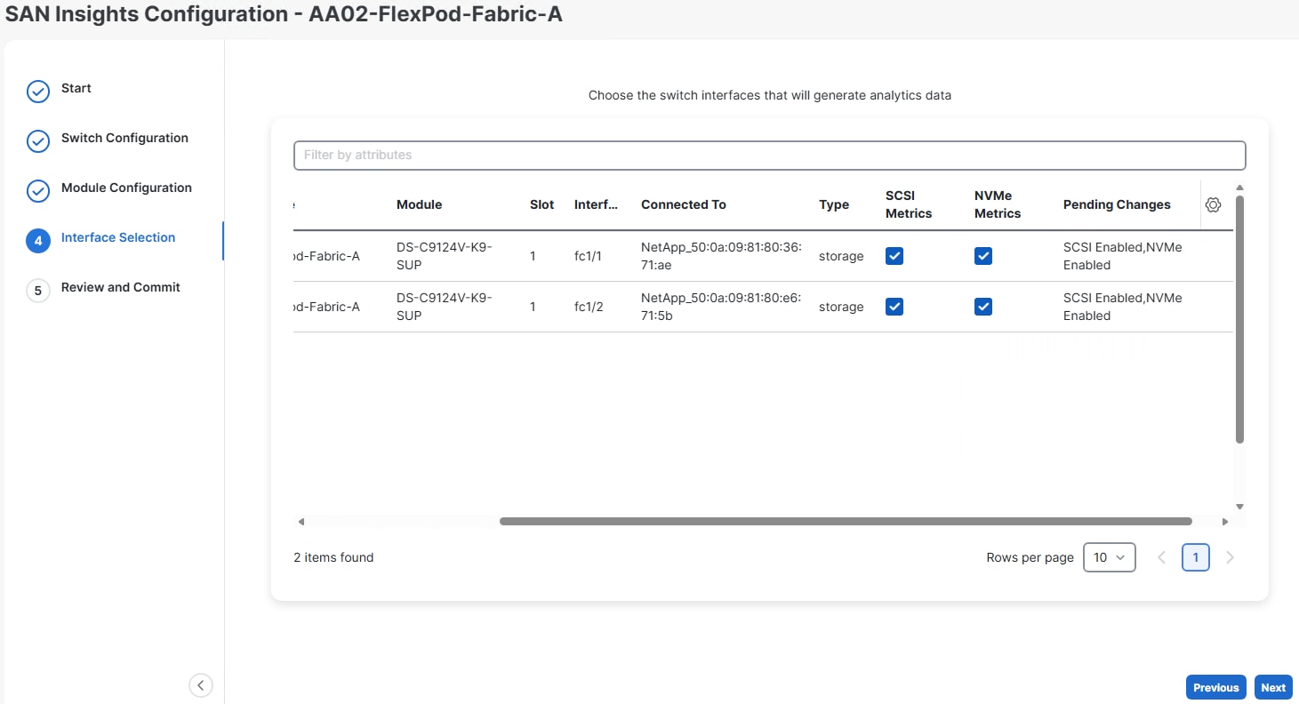
Step 4. In the Create backup schedule window, select the Remote storage location just created. Enter a minimum 8-character Encryption key. Enter a Scheduler date and time. Select a Frequency. Click Create.
Procedure 3. Configure Nexus Dashboard SAN Insights
Cisco Nexus Dashboard SAN Insights is a feature within Cisco Nexus Dashboard that provides comprehensive, real-time visibility and analytics for SAN (Storage Area Network) fabrics. It enables administrators to monitor fabric health, performance, and flow analytics end-to-end—from hosts to storage—using telemetry data streamed directly from Cisco MDS switches. The SAN Insights feature requires one MDS 9000 Series SAN Analytics or SAN_ANALYTICS_PKG Smart license per switch.
Step 1. Enable the Nexus Dashboard SAN Insights feature by selecting Admin > System Settings > Feature Management. Select the checkbox to the left of SAN Insights and click Apply. Wait for the Status to become Started.

Step 2. Select Manage > Fabrics. Select the checkbox to the left of FlexPod-Fabric-A. Using the Actions drop-down list, select Configure SAN Insights. Click Next.
Step 3. Select the checkbox to the left of the MDS switch. Click OK on the popup warnings. Use the slider to scroll right. From the Subscriptions drop-down list to select either SCSI for FC-only, NVMe for FC-NVMe-only, or SCSI & NVMe for both FC and FC-NVMe streaming statistics. Click OK on the popup warning. Use the Install Query drop-down list to select the Storage query. Click Next.
Step 4. 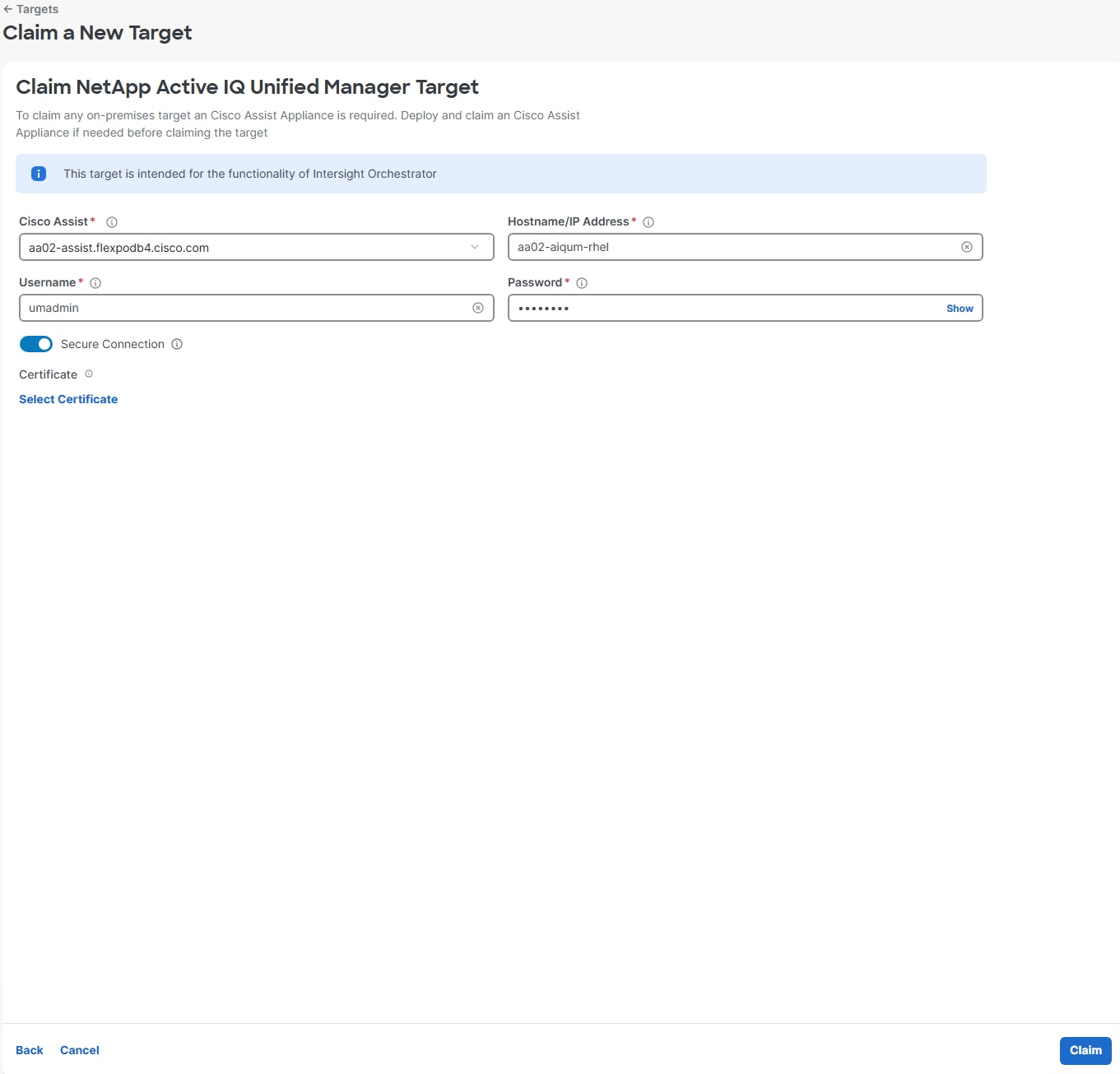 Click Next.
Step 5. Use the slider to scroll to the right and use the checkboxes to select metrics for FC interfaces. Click Next.

Step 6. Click Commit to complete the configuration. Wait for the Success Status. Click Close.
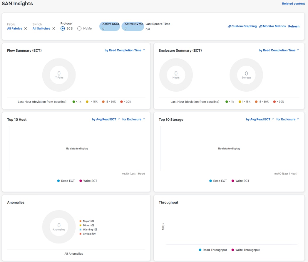
Step 7. Repeat Steps 2-6 to enable SAN Insights for FlexPod-Fabric-B.
Step 8. San Insights results can be seen by selecting Analyze > SAN Insights. You will not see any results until traffic is put on the fabric and telemetry is sent from the switches.

Claim Targets to Cisco Intersight
This chapter contains the following:
● Claim NetApp ONTAP Storage Targets
● Claim Cisco Nexus Switch Targets
● Claim Cisco MDS Switch Targets
If you have a management pod capable of running virtual machines, you can install Cisco Intersight Assist and NetApp Active IQ Unified Manager (AIQUM) and integrate a number of the FlexPod components to Cisco Intersight as targets. You will first need to install, claim, and configure the Intersight Assist appliance using the installation instructions found in the Cisco Intersight Virtual Appliance and Intersight Assist Getting Started Guide. When the Assist is claimed to Intersight, you can then begin claiming targets through the Assist.
Procedure 1. Claim NetApp ONTAP Storage Targets
NetApp ONTAP Storage Targets can be claimed through Intersight Assist and NetApp AIQUM. NetApp AIQUM can be installed on VMware from OVA, on Microsoft Windows, or on Red Hat Enterprise Linux 8 or 9. Install AIQUM with instructions from https://mysupport.netapp.com and configure AIQUM, making sure to enable the API Gateway feature in AIQUM and adding any NetApp ONTAP clusters in the FlexPod to AIQUM.
Step 1. Log into the Cisco Intersight portal.
Step 2. From the drop-down list, select System, then select Targets. Select Claim a New Target.
Step 3. Under Select Target Type, scroll down and select NetApp Active IQ Unified Manager and click Start.
Step 4. Make sure the correct Cisco Assist is selected and enter the AIQUM Hostname/IP Address or FQDN and then the username and password used to configure AIQUM. Click Claim.
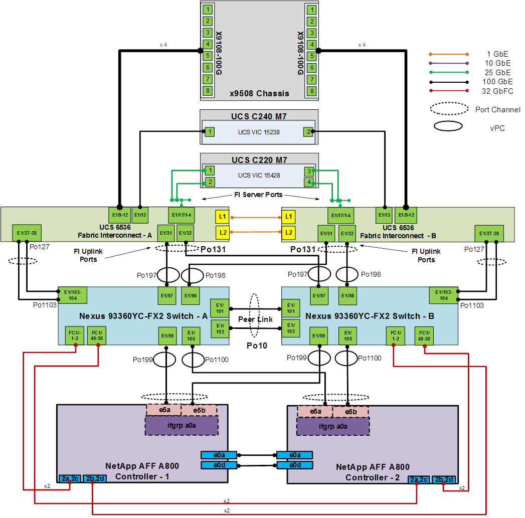
Step 5. When the target is successfully claimed, from the drop-down list select Operate > Storage. The NetApp storage cluster(s) configured in NetApp AIQUM appear in the list.
Procedure 2. Claim Cisco Nexus Switch Targets
A Cisco Nexus switch can be claimed two ways in Cisco Intersight. The first type of claim is using the switch’s native device connector and is used for the Intersight Connected TAC feature. The second type of claim utilizes Cisco Assist, provides inventory, and alerts information, and allows Intersight Cloud Orchestrator (ICO) workflows to be run on the switch.
Step 1. Log into the Cisco Intersight portal.
Step 2. From the drop-down list, select System, then select Targets. Select Claim a New Target.
Step 3. Under Select Target Type, select Cisco Nexus Switch and click Start.
Step 4. To claim the switch for the Intersight Connected TAC feature, leave Claim Target selected and open a ssh connection to the switch. Once connected to the switch, type the following commands:
show system device-connector claim-info
Step 5. Use the switch SerialNumber to fill in the Intersight Device ID field and the switch SecurityToken to fill in the Intersight Claim Code field. Select the appropriate Resource Group(s) and click Claim.
Step 6. Repeat steps 1 - 5 to claim all Nexus switches into Cisco Intersight.
Procedure 3. Claim Cisco MDS Switch Targets
A Cisco MDS switch can also be claimed two ways in Cisco Intersight. The first type of claim is using the switch’s native device connector and is used for the Intersight Connected TAC feature. The second type of claim utilizes Cisco Assist, provides inventory, and alerts information, and allows Intersight Cloud Orchestrator (ICO) workflows to be run on the switch. The second type of claim is currently in Tech Preview.
Step 1. Log into the Cisco Intersight portal.
Step 2. From the drop-down list, select System, then select Targets. Select Claim a New Target.
Step 3. Under Select Target Type, select Cisco MDS Switch and click Start.
Step 4. To claim the switch for the Intersight Connected TAC feature, leave Claim Target selected and open a ssh connection to the switch. Once connected to the switch, type the following commands:
show system device-connector claim-info
Step 5. Use the switch SerialNumber to fill in the Intersight Device ID field and the switch SecurityToken to fill in the Intersight Claim Code field. Select the appropriate Resource Group(s) and click Claim.
Step 6. Repeat steps 1 - 5 to claim all MDS switches into Cisco Intersight.
Procedure 4. Claim Nexus Dashboards
Step 1. Log into the Cisco Intersight portal.
Step 2. From the drop-down list, select System, then select Targets. Select Claim a New Target.
Step 3. Under Select Target Type, select Cisco Nexus Dashboard and click Start.
Step 4. In the Nexus Dashboard LAN interface, select Admin > Intersight. The Device ID and Claim Code are shown.
Step 5. Copy the Device ID and Claim Code field text into Intersight. Select the appropriate Resource Group(s) and click Claim.
Step 6. Repeat this procedure to add the Nexus Dashboard SAN.
John George, Technical Marketing Engineer, Cisco Systems, Inc.
John has been involved in designing, developing, validating, and supporting the FlexPod Converged Infrastructure since it was developed 13 years ago. Before his role with FlexPod, he supported and administered a large worldwide training network and VPN infrastructure. John holds a master’s degree in Computer Engineering from Clemson University.
Abhinav Singh, Senior Technical Marketing Engineer, Converged Infrastructure Solutions, NetApp
Abhinav Singh is a Senior Technical Marketing Engineer in the Converged Infrastructure Solutions team at NetApp, with over 15 years of experience in data center virtualization, networking, and storage. Abhinav specializes in designing, validating, implementing, and supporting converged infrastructure solutions, with a focus on AI/ML, data center virtualization, hybrid cloud, Kubernetes, software-defined networking (SDN), and enterprise storage platforms. Abhinav holds a Bachelor’s degree in Electrical and Electronics. Engineering.
Acknowledgements
For their support and contribution to the design, validation, and creation of this Cisco Validated Design, the authors would like to thank:
● Archana Sharma, Principal Technical Marketing Engineer, Cisco Systems, Inc.
● Kamini Singh, Technical Marketing Engineer, NetApp
This appendix contains the following:
● Cisco Nexus Switch Manual Configuration
● FlexPod with Cisco Nexus SAN Switching Configuration – Part 1
● FlexPod with Cisco Nexus 93360YC-FX2 SAN Switching Configuration – Part 2
Note: The features and functionality explained in this Appendix are optional configurations which can be helpful in configuring and managing the FlexPod deployment.
Cisco Nexus Switch Manual Configuration
This configuration can be done if it is not desired to use Nexus Dashboard to configure the switches in a switching fabric.
Procedure 1. Configure the Cisco Nexus switches from the management workstation
Step 1. Log into both Nexus switches as admin using ssh.
Step 2. Enable features on both Nexus switches:
config t
feature nxapi
feature udld
feature interface-vlan
feature lacp
feature vpc
feature lldp
Step 3. Set global configurations on both Nexus switches:
spanning-tree port type network default
spanning-tree port type edge bpduguard default
spanning-tree port type edge bpdufilter default
port-channel load-balance src-dst l4port
ntp server <global-ntp-server-ip> use-vrf management – Repeat this command to add additional NTP servers
clock timezone <timezone> <hour-offset> <minute-offset>
clock summer-time <timezone> <start-week> <start-day> <start-month> <start-time> <end-week> <end-day> <end-month> <end-time> <offset-minutes>
Note: It is important to configure the local time so that logging time alignment and any backup schedules are correct. For more information on configuring the timezone and daylight savings time or summer time, see the Cisco Nexus 9000 NX-OS Fundamentals Configuration Guide, Release 10.3(x). Sample clock commands for the United States Eastern timezone are:
clock timezone EST -5 0
clock summer-time EDT 2 Sunday March 02:00 1 Sunday November 02:00 60
Step 4. Optionally, enable NTP Distribution on both Nexus switches:
ntp master 3 – Set the stratum level appropriately
ntp peer <other-switch-mgmt-ip> use-vrf management
Step 5. Add the VLANs to both Nexus switches:
vlan <native-vlan-id>
name Native
vlan <oob-mgmt-vlan-id>
name OOB-MGMT
Step 6. Add individual port descriptions for troubleshooting and enable UDLD for Cisco UCS Fabric Interconnect interfaces to Cisco Nexus A:
interface Eth1/1
description <st-clustername>-01:e6a
interface Eth1/2
description <st-clustername>-02:e6a
interface Eth1/5
description <ucs-domainname>-A:1/63
udld enable
interface Eth1/6
description <ucs-domainname>-B:1/63
udld enable
interface Eth1/21
description <nexus-b-hostname>:1/21
interface Eth1/22
description <nexus-b-hostname>:1/22
interface Eth1/24
description Uplink-Switch
Note: For fibre optic connections to Cisco UCS systems (AOC or SFP-based), entering udld enable will result in a message stating that this command is not applicable to fiber ports. This message is expected.
Step 7. Add individual port descriptions for troubleshooting and enable UDLD for Cisco UCS Fabric Interconnect interfaces to Cisco Nexus B:
interface Eth1/1
description <st-clustername>-01:e6b
interface Eth1/2
description <st-clustername>-02:e6b
interface Eth1/5
description <ucs-domainname>-A:1/64
udld enable
interface Eth1/6
description <ucs-domainname>-B:1/64
udld enable
interface Eth1/21
description <nexus-a-hostname>:1/21
interface Eth1/22
description <nexus-a-hostname>:1/22
interface Eth1/24
description Uplink-Switch
Step 8. Create the necessary port channels in both Nexus switches:
interface Po10
description vPC peer-link
interface Eth1/21-22
channel-group 10 mode active
no shutdown
interface Po11
description <st-clustername>-01
interface Eth1/1
channel-group 11 mode active
no shutdown
interface Po12
description <st-clustername>-02
interface Eth1/2
channel-group 12 mode active
no shutdown
interface Po15
description <ucs-domainname>-A
interface Eth1/5
channel-group 15 mode active
no shutdown
interface Po16
description <ucs-domainname>-B
interface Eth1/6
channel-group 16 mode active
no shutdown
interface Po124
description MGMT-Uplink
interface Eth1/24
channel-group 124 mode active
no shutdown
exit
copy run start
Step 9. Configure port channel parameters in both Nexus switches:
interface Po10
switchport mode trunk
switchport trunk native vlan <native-vlan-id>
switchport trunk allowed vlan all
spanning-tree port type network
interface Po11
switchport mode trunk
switchport trunk allowed vlan none
spanning-tree port type edge trunk
mtu 9216
interface Po12
switchport mode trunk
switchport trunk allowed vlan none
spanning-tree port type edge trunk
mtu 9216
interface Po15
switchport mode trunk
switchport trunk native vlan <native-vlan-id>
switchport trunk allowed vlan <native-vlan-id>,<oob-mgmt-vlan-id>
spanning-tree port type edge trunk
mtu 9216
interface Po15
switchport mode trunk
switchport trunk native vlan <native-vlan-id>
switchport trunk allowed vlan <native-vlan-id>,<oob-mgmt-vlan-id>
spanning-tree port type edge trunk
mtu 9216
interface Po124
switchport mode trunk
switchport trunk native vlan <native-vlan-id>
switchport trunk allowed vlan <native-vlan-id>,<oob-mgmt-vlan-id>
spanning-tree port type normal
mtu 9216
exit
copy run start
Step 10. Configure virtual port channels (vPCs) in Cisco Nexus A:
vpc domain <nexus-vpc-domain-id>
role priority 10
peer-keepalive destination <nexus-B-mgmt0-ip> source <nexus-A-mgmt0-ip>
peer-switch
peer-gateway
auto-recovery
delay restore 150
ip arp synchronize
interface Po10
vpc peer-link
interface Po11
vpc 11
interface Po12
vpc 12
interface Po15
vpc 15
interface Po16
vpc 16
interface Po124
vpc 124
exit
copy run start
Step 11. Configure virtual port channels (vPCs) in Cisco Nexus B:
vpc domain <nexus-vpc-domain-id>
role priority 20
peer-keepalive destination <nexus-A-mgmt0-ip> source <nexus-B-mgmt0-ip>
peer-switch
peer-gateway
auto-recovery
delay restore 150
ip arp synchronize
interface Po10
vpc peer-link
interface Po11
vpc 11
interface Po12
vpc 12
interface Po15
vpc 15
interface Po16
vpc 16
interface Po124
vpc 124
exit
copy run start
Step 12. The following commands can be used to see the switch configuration and status:
show run
show vpc
show port-channel summary
show ntp peer-status
show cdp neighbors
show lldp neighbors
show run int
show int
show udld neighbors
show int status
FlexPod with Cisco Nexus SAN Switching Configuration – Part 1
If the Cisco Nexus switches are to be used for both LAN and SAN switching in the FlexPod configuration, either an automated configuration with Ansible or a manual configuration can be done. For either configuration method, the following base switch setup must be done manually. Figure 5 shows the validation lab cabling for this setup.

FlexPod Cisco Nexus 93360YC-FX2 SAN Switching Base Configuration
The following procedures describe how to configure the Cisco Nexus 93360YC-FX2 switches for use in a base FlexPod environment that uses the switches for both LAN and SAN switching. This procedure assumes you’re using Cisco Nexus 9000 10.3(4a)M. This procedure also assumes that you have created an FCoE Uplink Port Channel on the appropriate ports in the Cisco UCS IMM Port Policies for each UCS fabric interconnect.
Procedure 1. Set Up Initial Configuration in Cisco Nexus 93360YC-FX2 A
Step 1. Configure the switch:
Note: On initial boot and connection to the serial or console port of the switch, the NX-OS setup should automatically start and attempt to enter Power on Auto Provisioning.
Abort Power On Auto Provisioning [yes - continue with normal setup, skip - bypass password and basic configuration, no - continue with Power On Auto Provisioning] (yes/skip/no)[no]: yes
Disabling POAP.......Disabling POAP
poap: Rolling back, please wait... (This may take 5-15 minutes)
---- System Admin Account Setup ----
Do you want to enforce secure password standard (yes/no) [y]: Enter
Enter the password for "admin": <password>
Confirm the password for "admin": <password>
Would you like to enter the basic configuration dialog (yes/no): yes
Create another login account (yes/no) [n]: Enter
Configure read-only SNMP community string (yes/no) [n]: Enter
Configure read-write SNMP community string (yes/no) [n]: Enter
Enter the switch name: <nexus-A-hostname>
Continue with Out-of-band (mgmt0) management configuration? (yes/no) [y]: Enter
Mgmt0 IPv4 address: <nexus-A-mgmt0-ip>
Mgmt0 IPv4 netmask: <nexus-A-mgmt0-netmask>
Configure the default gateway? (yes/no) [y]: Enter
IPv4 address of the default gateway: <nexus-A-mgmt0-gw>
Configure advanced IP options? (yes/no) [n]: Enter
Enable the telnet service? (yes/no) [n]: Enter
Enable the ssh service? (yes/no) [y]: Enter
Type of ssh key you would like to generate (dsa/rsa) [rsa]: Enter
Number of rsa key bits <1024-2048> [1024]: Enter
Configure the ntp server? (yes/no) [n]: Enter
Configure default interface layer (L3/L2) [L2]: Enter
Configure default switchport interface state (shut/noshut) [noshut]: shut
Enter basic FC configurations (yes/no) [n]: y
Configure default physical FC switchport interface state (shut/noshut) [shut]: Enter
Configure default switchport trunk mode (on/off/auto) [on]: auto
Configure default zone policy (permit/deny) [deny]: Enter
Enable full zoneset distribution? (yes/no) [n]: y
Configure CoPP system profile (strict/moderate/lenient/dense) [strict]: Enter
Would you like to edit the configuration? (yes/no) [n]: Enter
Step 2. Review the configuration summary before enabling the configuration:
Use this configuration and save it? (yes/no) [y]: Enter
Procedure 2. Set Up Initial Configuration in Cisco Nexus 93360YC-FX2 B
Step 1. Configure the switch:
Note: On initial boot and connection to the serial or console port of the switch, the NX-OS setup should automatically start and attempt to enter Power on Auto Provisioning.
Abort Power On Auto Provisioning [yes - continue with normal setup, skip - bypass password and basic configuration, no - continue with Power On Auto Provisioning] (yes/skip/no)[no]: yes
Disabling POAP.......Disabling POAP
poap: Rolling back, please wait... (This may take 5-15 minutes)
---- System Admin Account Setup ----
Do you want to enforce secure password standard (yes/no) [y]: Enter
Enter the password for "admin": <password>
Confirm the password for "admin": <password>
Would you like to enter the basic configuration dialog (yes/no): yes
Create another login account (yes/no) [n]: Enter
Configure read-only SNMP community string (yes/no) [n]: Enter
Configure read-write SNMP community string (yes/no) [n]: Enter
Enter the switch name: <nexus-B-hostname>
Continue with Out-of-band (mgmt0) management configuration? (yes/no) [y]: Enter
Mgmt0 IPv4 address: <nexus-B-mgmt0-ip>
Mgmt0 IPv4 netmask: <nexus-B-mgmt0-netmask>
Configure the default gateway? (yes/no) [y]: Enter
IPv4 address of the default gateway: <nexus-B-mgmt0-gw>
Configure advanced IP options? (yes/no) [n]: Enter
Enable the telnet service? (yes/no) [n]: Enter
Enable the ssh service? (yes/no) [y]: Enter
Type of ssh key you would like to generate (dsa/rsa) [rsa]: Enter
Number of rsa key bits <1024-2048> [1024]: Enter
Configure the ntp server? (yes/no) [n]: Enter
Configure default interface layer (L3/L2) [L2]: Enter
Configure default switchport interface state (shut/noshut) [noshut]: shut
Enter basic FC configurations (yes/no) [n]: y
Configure default physical FC switchport interface state (shut/noshut) [shut]: Enter
Configure default switchport trunk mode (on/off/auto) [on]: auto
Configure default zone policy (permit/deny) [deny]: Enter
Enable full zoneset distribution? (yes/no) [n]: y
Configure CoPP system profile (strict/moderate/lenient/dense) [strict]: Enter
Would you like to edit the configuration? (yes/no) [n]: Enter
Step 2. Review the configuration summary before enabling the configuration:
Use this configuration and save it? (yes/no) [y]: Enter
Note: SAN switching requires both the SAN_ENTERPRISE_PKG and FC_PORT_ACTIVATION_PKG licenses. Ensure these licenses are installed on each Nexus switch.
Note: This section is structured as a green field switch setup. If existing switches that are switching active traffic are being setup, execute this procedure down through Perform TCAM Carving and Configure Unified Ports in Cisco Nexus 93360YC-FX22 A and B first on one switch and then when that is completed, execute on the other switch.
Procedure 3. Install feature-set fcoe in Cisco Nexus 93360YC-FX2 A and B
Step 1. Run the following commands to set global configurations:
config t
install feature-set fcoe
feature-set fcoe
system default switchport trunk mode auto
system default switchport mode F
Note: These steps are provided in case the basic FC configurations were not configured in the switch setup script de-tailed in the previous section.
Procedure 4. Set System-Wide QoS Configurations in Cisco Nexus 93360YC-FX2 A and B
Step 1. Run the following commands to set global configurations:
config t
system qos
service-policy type queuing input default-fcoe-in-que-policy
service-policy type queuing output default-fcoe-8q-out-policy
service-policy type network-qos default-fcoe-8q-nq-policy
copy run start
Procedure 5. Perform TCAM Carving and Configure Unified Ports (UP) in Cisco Nexus 93360YC-FX2 A and B
Note: SAN switching requires TCAM carving for lossless fibre channel no-drop support. Also, unified ports need to be converted to fc ports.
Note: On the Cisco Nexus 93360YC-FX2, UP ports are converted to FC in groups of 4 in columns, for example, 1,2,49,50.
Step 1. Run the following commands:
hardware access-list tcam region ing-racl 1536
hardware access-list tcam region ing-ifacl 256
hardware access-list tcam region ing-redirect 256
slot 1
port 1-4,49-52 type fc
copy running-config startup-config
reload
This command will reboot the system. (y/n)? [n] y
Step 2. After the switch reboots, log back in as admin. Run the following commands:
show hardware access-list tcam region |i i ing-racl
show hardware access-list tcam region |i i ing-ifacl
show hardware access-list tcam region |i i ing-redirect
show int status
FlexPod with Cisco Nexus 93360YC-FX2 SAN Switching Configuration – Part 2
Note: If the Cisco Nexus 93360YC-FX2 switch is being used for SAN Switching, this section should be completed in place of the Cisco MDS section of this document.
Procedure 1. FlexPod Cisco MDS Switch Manual Configuration
Step 1. Connect to both Cisco MDS switches with the admin user using ssh.
Step 2. Configure features on both MDS switches:
configure terminal
feature nxapi
feature npiv
feature fport-channel-trunk
Step 3. Configure NTP servers and local time configuration. It is important to configure the local time so that logging time alignment and any backup schedules are correct. For more information on configuring the timezone and daylight savings time or summertime, see the Cisco MDS 9000 Series Fundamentals Configuration Guide, Release 9.x.
ntp server <nexus-A-mgmt0-ip>
ntp server <nexus-B-mgmt0-ip>
clock timezone <timezone> <hour-offset> <minute-offset>
clock summer-time <timezone> <start-week> <start-day> <start-month> <start-time> <end-week> <end-day> <end-month> <end-time> <offset-minutes>
copy running-config startup-config
Sample clock commands for the United States Eastern timezone are:
clock timezone EST -5 0
clock summer-time EDT 2 Sunday March 02:00 1 Sunday November 02:00 60
copy running-config startup-config
Step 4. Configure storage individual ports on Cisco MDS A and add to VSAN database:
interface fc1/1
switchport description <st-clustername>-01:2a
switchport speed 32000
switchport trunk mode off
no shutdown
exit
interface fc1/2
switchport description <st-clustername>-02:2a
switchport speed 32000
switchport trunk mode off
no shutdown
exit
interface fc1/49
switchport description <st-clustername>-01:2c
switchport speed 32000
switchport trunk mode off
no shutdown
exit
interface fc1/50
switchport description <st-clustername>-02:2c
switchport speed 32000
switchport trunk mode off
no shutdown
exit
vsan database
vsan <vsan-a-id>
vsan <vsan-a-id> name FlexPod-Fabric-A
exit
zone smart-zoning enable vsan <vsan-a-id>
vsan database
vsan <vsan-a-id> interface fc1/1
vsan <vsan-a-id> interface fc1/2
vsan <vsan-a-id> interface fc1/3
vsan <vsan-a-id> interface fc1/4
exit
Note: If VSAN trunking is not being used between the Cisco UCS Fabric Interconnects and the MDS switches, do not enter “switchport trunk allowed vsan <vsan-a-id>” for interface port-channel15. Also, the default setting of the switchport trunk mode auto is being used for the port channel.
Step 5. Configure storage individual ports on Cisco MDS B:
interface fc1/1
switchport description <st-clustername>-01:2b
switchport speed 32000
switchport trunk mode off
no shutdown
exit
interface fc1/2
switchport description <st-clustername>-02:2b
switchport speed 32000
switchport trunk mode off
no shutdown
exit
interface fc1/49
switchport description <st-clustername>-01:2d
switchport speed 32000
switchport trunk mode off
no shutdown
exit
interface fc1/50
switchport description <st-clustername>-02:2d
switchport speed 32000
switchport trunk mode off
no shutdown
exit
vsan database
vsan <vsan-b-id>
vsan <vsan-b-id> name FlexPod-Fabric-B
exit
zone smart-zoning enable vsan <vsan-a-id>
vsan database
vsan <vsan-b-id> interface fc1/1
vsan <vsan-b-id> interface fc1/2
vsan <vsan-b-id> interface fc1/3
vsan <vsan-b-id> interface fc1/4
exit
Note: If VSAN trunking is not being used between the Cisco UCS Fabric Interconnects and the MDS switches, do not enter “switchport trunk allowed vsan <vsan-B-id>” for interface port-channel15. Also, the default setting of the switchport trunk mode auto is being used for the port channel.
Step 6. If configuring FC links between the Cisco UCS FIs and Cisco Nexus SAN switches, configure the following in Cisco Nexus A:
interface fc1/3
switchport description <ucs-domainname>-A:1/35/1
channel-group 15
no shutdown
exit
interface fc1/4
switchport description <ucs-domainname>-A:1/35/2
channel-group 15
no shutdown
exit
interface fc1/51
switchport description <ucs-domainname>-A:1/35/3
channel-group 15
no shutdown
exit
interface fc1/52
switchport description <ucs-domainname>-A:1/35/4
channel-group 15
no shutdown
exit
interface san-port-channel13
channel mode active
switchport trunk allowed vsan <vsan-a-id>
switchport description <ucs-domainname>-A
switchport speed 32000
no shutdown
exit
vsan database
vsan <vsan-a-id> interface san-port-channel13
exit
copy r s
Step 7. If configuring FC links between the Cisco UCS FIs and Cisco Nexus SAN switches, configure the following in Cisco Nexus B:
interface fc1/3
switchport description <ucs-domainname>-B:1/35/1
channel-group 15
no shutdown
exit
interface fc1/4
switchport description <ucs-domainname>-B:1/35/2
channel-group 15
no shutdown
exit
interface fc1/51
switchport description <ucs-domainname>-B:1/35/3
channel-group 15
no shutdown
exit
interface fc1/52
switchport description <ucs-domainname>-B:1/35/4
channel-group 15
no shutdown
exit
interface san-port-channel13
channel mode active
switchport trunk allowed vsan <vsan-B-id>
switchport description <ucs-domainname>-B
switchport speed 32000
no shutdown
exit
vsan database
vsan <vsan-b-id> interface san-port-channel13
exit
copy r s
Step 8. If configuring FCoE links between the Cisco UCS FIs and Cisco Nexus SAN switches, configure the following in Cisco Nexus A:
vlan <vsan-a-id>
name FCoE-VLAN
fcoe vsan <vsan-a-id>
int eth1/103
description <ucs-domainname>-A:Eth1/27
int eth1/104
description <ucs-domainname>-A:Eth1/28
int eth1/103-104
channel-group 1103 mode active
no shutdown
int po1103
description <ucs-domainname>-A:FCoE
switchport mode trunk
switchport trunk native vlan <native-vlan-id>
switchport trunk allowed vlan <vsan-a-id>
spanning-tree port type edge trunk
mtu 9216
service-policy type qos input default-fcoe-in-policy
int vfc1103
bind interface port-channel1103
switchport trunk allowed vsan <vsan-a-id>
switchport description <ucs-domainname>-A:FCoE
switchport trunk mode on
vsan database
vsan <vsan-a-id> interface vfc1103
exit
copy r s
Step 9. If configuring FCoE links between the Cisco UCS FIs and Cisco Nexus SAN switches, configure the following in Cisco Nexus B:
vlan <vsan-b-id>
name FCoE-VLAN
fcoe vsan <vsan-b-id>
int eth1/103
description <ucs-domainname>-B:Eth1/27
int eth1/104
description <ucs-domainname>-B:Eth1/28
int eth1/103-104
channel-group 1103 mode active
no shutdown
int po1103
description <ucs-domainname>-B:FCoE
switchport mode trunk
switchport trunk native vlan <native-vlan-id>
switchport trunk allowed vlan <vsan-b-id>
spanning-tree port type edge trunk
mtu 9216
service-policy type qos input default-fcoe-in-policy
int vfc1103
bind interface port-channel1103
switchport trunk allowed vsan <vsan-b-id>
switchport description <ucs-domainname>-B:FCoE
switchport trunk mode on
vsan database
vsan <vsan-b-id> interface vfc1103
exit
copy r s
Procedure 2. Switch Testing Commands
Step 1. The following commands can be used to check for correct switch configuration:
Note: Some of these commands need to run after further configuration of the FlexPod components are complete to see complete results.
show run
show run int
show int
show int status
show int brief
show flogi database
show device-alias database
show zone
show zoneset
show zoneset active
Procedure 1. Cisco Nexus and MDS Backups
The configuration of the Cisco Nexus 9000 and Cisco MDS 9124V switches can be backed up manually at any time with the copy command, but automated backups can be enabled using the NX-OS feature scheduler.
An example of setting up automated configuration backups of one of the NX-OS switches is shown below:
config t
feature scheduler
scheduler logfile size 1024
scheduler job name backup-cfg
copy running-config tftp://<server-ip>/$(SWITCHNAME)-cfg.$(TIMESTAMP) vrf management
exit
scheduler schedule name daily
job name backup-cfg
time daily 2:00
end
Note: Using “vrf management” in the copy command is only needed when Mgmt0 interface is part of VRF management. “vrf management is not needed in Cisco MDS switches.
Step 1. Verify the scheduler job has been correctly setup using following command(s):
show scheduler job
Job Name: backup-cfg
--------------------
copy running-config tftp://10.1.156.150/$(SWITCHNAME)-cfg.$(TIMESTAMP) vrf management
==============================================================================
show scheduler schedule
Schedule Name : daily
---------------------------
User Name : admin
Schedule Type : Run every day at 2 Hrs 0 Mins
Last Execution Time : Yet to be executed
-----------------------------------------------
Job Name Last Execution Status
-----------------------------------------------
backup-cfg -NA-
==============================================================================
The documentation for the feature scheduler can be found here: https://www.cisco.com/c/en/us/td/docs/dcn/nx-os/nexus9000/102x/configuration/system-management/cisco-nexus-9000-series-nx-os-system-management-configuration-guide-102x/m-configuring-the-scheduler-10x.html
Procedure 2. NetApp ONTAP Configuration Backup
The configuration backup files of the NetApp ONTAP cluster and nodes are automatically created according to the following schedules:
● Every 8 hours
● Daily
● Weekly
At each of these times, a node configuration backup file is created on each healthy node in the cluster. All of these node configuration backup files are then collected in a single cluster configuration backup file along with the replicated cluster configuration and saved on one or more nodes in the cluster.
An example of viewing the ONTAP cluster configuration backup files is shown below:
AA16-A400::> set advanced
Warning: These advanced commands are potentially dangerous; use them only when directed to do so by NetApp personnel.
Do you want to continue? {y|n}: y
AA16-A400::*> row 0
(rows)
AA16-A400::*> system configuration backup show
Node Backup Name Time Size
--------- ----------------------------------------- ------------------ -----
AA16-A400-01 AA16-A400.8hour.2023-08-31.18_15_00.7z 08/31 18:15:00 34.60MB
AA16-A400-01 AA16-A400.8hour.2023-09-01.02_15_00.7z 09/01 02:15:00 35.65MB
AA16-A400-01 AA16-A400.8hour.2023-09-01.10_15_00.7z 09/01 10:15:00 36.05MB
AA16-A400-01 AA16-A400.daily.2023-08-31.00_10_01.7z 08/31 00:10:01 34.87MB
AA16-A400-01 AA16-A400.daily.2023-09-01.00_10_01.7z 09/01 00:10:01 35.09MB
AA16-A400-01 AA16-A400.weekly.2023-08-27.00_15_00.7z 08/27 00:15:00 23.50MB
AA16-A400-02 AA16-A400.8hour.2023-09-01.02_15_00.7z 09/01 02:15:00 35.65MB
AA16-A400-02 AA16-A400.8hour.2023-09-01.10_15_00.7z 09/01 10:15:00 36.05MB
AA16-A400-02 AA16-A400.daily.2023-08-30.00_10_00.7z 08/30 00:10:00 32.69MB
AA16-A400-02 AA16-A400.daily.2023-08-31.00_10_01.7z 08/31 00:10:01 34.87MB
AA16-A400-02 AA16-A400.daily.2023-09-01.00_10_01.7z 09/01 00:10:01 35.09MB
AA16-A400-02 AA16-A400.weekly.2023-08-27.00_15_00.7z 08/27 00:15:00 23.50MB
12 entries were displayed.
AA16-A400::*> set admin
AA16-A400::>
You can use the system configuration backup settings commands to manage configuration backup schedules and specify a remote URL (HTTP, HTTPS, FTP, FTPS, or TFTP ) where the configuration backup files will be uploaded in addition to the default locations in the cluster.
An example of setting up an automated ONTAP cluster configuration backup upload destination using TFTP is shown below:
AA16-A400::> set advanced
Warning: These advanced commands are potentially dangerous; use them only when directed to do so by NetApp personnel.
Do you want to continue? {y|n}: y
AA16-A400::*> system configuration backup setting modify -destination tftp://10.1.156.150/ONTAP
AA16-A400::*> system configuration backup setting show
Backup Destination URL Username
-------------------------------------------------- -------------
tftp://10.1.156.150/ONTAP
AA16-A400::*> set admin
AA16-A400::>
CVD Program
ALL DESIGNS, SPECIFICATIONS, STATEMENTS, INFORMATION, AND RECOMMENDATIONS (COLLECTIVELY, "DESIGNS") IN THIS MANUAL ARE PRESENTED "AS IS," WITH ALL FAULTS. CISCO AND ITS SUPPLIERS DISCLAIM ALL WARRANTIES, INCLUDING, WITHOUT LIMITATION, THE WARRANTY OF MERCHANTABILITY, FITNESS FOR A PARTICULAR PURPOSE AND NONINFRINGEMENT OR ARISING FROM A COURSE OF DEALING, USAGE, OR TRADE PRACTICE. IN NO EVENT SHALL CISCO OR ITS SUPPLIERS BE LIABLE FOR ANY INDIRECT, SPECIAL, CONSEQUENTIAL, OR INCIDENTAL DAMAGES, INCLUDING, WITHOUT LIMITATION, LOST PROFITS OR LOSS OR DAMAGE TO DATA ARISING OUT OF THE USE OR INABILITY TO USE THE DESIGNS, EVEN IF CISCO OR ITS SUPPLIERS HAVE BEEN ADVISED OF THE POSSIBILITY OF SUCH DAMAGES.
THE DESIGNS ARE SUBJECT TO CHANGE WITHOUT NOTICE. USERS ARE SOLELY RESPONSIBLE FOR THEIR APPLICATION OF THE DESIGNS. THE DESIGNS DO NOT CONSTITUTE THE TECHNICAL OR OTHER PROFESSIONAL ADVICE OF CISCO, ITS SUPPLIERS OR PARTNERS. USERS SHOULD CONSULT THEIR OWN TECHNICAL ADVISORS BEFORE IMPLE-MENTING THE DESIGNS. RESULTS MAY VARY DEPENDING ON FACTORS NOT TESTED BY CISCO.
CCDE, CCENT, Cisco Eos, Cisco Lumin, Cisco Nexus, Cisco StadiumVision, Cisco TelePresence, Cisco WebEx, the Cisco logo, DCE, and Welcome to the Human Network are trademarks; Changing the Way We Work, Live, Play, and Learn and Cisco Store are service marks; and Access Registrar, Aironet, AsyncOS, Bringing the Meeting To You, Catalyst, CCDA, CCDP, CCIE, CCIP, CCNA, CCNP, CCSP, CCVP, Cisco, the Cisco Certified Internetwork Expert logo, Cisco IOS, Cisco Press, Cisco Systems, Cisco Systems Capital, the Cisco Systems logo, Cisco Unified Computing System (Cisco UCS), Cisco UCS B-Series Blade Servers, Cisco UCS C-Series Rack Servers, Cisco UCS S-Series Storage Servers, Cisco UCS X-Series, Cisco UCS Manager, Cisco UCS Management Software, Cisco Unified Fabric, Cisco Application Centric Infrastructure, Cisco Nexus 9000 Series, Cisco Nexus 7000 Series. Cisco Prime Data Center Network Manager, Cisco NX-OS Software, Cisco MDS Series, Cisco Unity, Collaboration Without Limitation, EtherFast, EtherSwitch, Event Center, Fast Step, Follow Me Browsing, FormShare, GigaDrive, HomeLink, Internet Quotient, IOS, iPhone, iQuick Study, LightStream, Linksys, MediaTone, MeetingPlace, MeetingPlace Chime Sound, MGX, Networkers, Networking Academy, Network Registrar, PCNow, PIX, PowerPanels, ProConnect, ScriptShare, SenderBase, SMARTnet, Spectrum Expert, StackWise, The Fastest Way to Increase Your Internet Quotient, TransPath, WebEx, and the WebEx logo are registered trade-marks of Cisco Systems, Inc. and/or its affiliates in the United States and certain other countries. (LDW_P5)
All other trademarks mentioned in this document or website are the property of their respective owners. The use of the word partner does not imply a partnership relationship between Cisco and any other company. (0809R)