- Prerequisites for Initial Switch configuration
- Identify Configuration Values
- Assign Initial Management Information
Initial Switch Configuration
This workflow explains how to configure the basic settings on a switch.
Whether the configuration deployment of a switch is completed all at once or done in phases, the basic switch settings must first be configured. The initial management configuration includes setting IP addresses, passwords, and VLANs, which the prerequisites for future feature configuration.
Prerequisites for Initial Switch configuration
Refer to the switch Hardware Installation Guide to complete the following tasks:
2.![]() Connect the StackWise cables.
Connect the StackWise cables.
5.![]() Provision your upstream switch.
Provision your upstream switch.
6.![]() Connect at least one Ethernet cable from the uplink interface on the switch to the upstream switch or router.
Connect at least one Ethernet cable from the uplink interface on the switch to the upstream switch or router.
Identify Configuration Values
We recommend that you identify certain switch configuration values in advance so that you can proceed with this section without interruption. We recommend that you take a print out of Table 2, and, as you follow the configuration sequence, replace the values in column B with your values in column C.

Note![]() Replace the blue italicized example values with your own values.
Replace the blue italicized example values with your own values.
|
|
|
|
|---|---|---|
Note![]() The configuration examples provided in this document begin in global configuration mode, unless noted otherwise.
The configuration examples provided in this document begin in global configuration mode, unless noted otherwise.
Assign Initial Management Information
- The following configurations should be performed in the same sequence in which they are listed here.
- Users can now proceed to the Configure Secure HTTPS ans Secure Shell for Secure LAN Management section.
- Configure SNMP for Remote Management
- Configure Local Login and Password for Switch Access
- Configure Centralized User Authentication Through TACACS+
- Configure a Management IP Address on an Out-of-Band Interface
- Configure a Management IP Address on an In-Band Interface
- Create a Management VLAN in Hardware
- Enter the show running-configuration command to display the initial management information for the switch.
Note![]() The following configurations should be performed in the same sequence in which they are listed here.
The following configurations should be performed in the same sequence in which they are listed here.
Configure the Hostname for Switch Identification
Step 1![]() Configure the hostname on a switch to identify the switch in your network. By default, the system name and prompt are Switch.
Configure the hostname on a switch to identify the switch in your network. By default, the system name and prompt are Switch.
Set the hostname for the switch product family, the role of the switch in your network, and the switch location.
Note that the system name is also used as the system prompt.
If you have not configured a system prompt, the first 20 characters of the system name are used as the system prompt. A greater-than symbol [>] is appended. The prompt is updated whenever the system name changes.
This example is for the switch serving as an access layer switch located on the first floor of Building 1

Note![]() Users can now proceed to the Configure Secure HTTPS ans Secure Shell for Secure LAN Management section.
Users can now proceed to the Configure Secure HTTPS ans Secure Shell for Secure LAN Management section.
Configure Secure HTTPS and Secure Shell for Secure LAN Management
Step 2![]() Disable the HTTP and Telnet unencrypted protocols on the switch.
Disable the HTTP and Telnet unencrypted protocols on the switch.

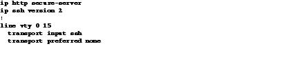
Step 3![]() Configure Secure HTTP (HTTPS) and Secure Shell (SSH) to enable secure management of the switch.
Configure Secure HTTP (HTTPS) and Secure Shell (SSH) to enable secure management of the switch.
Enabling HTTPS automatically generates a cryptographic key to use the service. When SSH is configured after HTTPS, you do not have to explicitly generate the cryptographic key that SSH requires, unless you want to change the default key size.
We recommend that you use the transport preferred none command on the VTY lines to prevent connection attempt errors from the CLI prompt. Without this command, your IP name server may become unreachable, and long timeout delays may occur..
Note![]() If the switch acts as a Web authentication server or as an authentication proxy, then do not disable the HTTP server by executing the no ip http server command.
If the switch acts as a Web authentication server or as an authentication proxy, then do not disable the HTTP server by executing the no ip http server command.
Configure SNMP for Remote Management
Step 4![]() Enable Simple Network Management Protocol (SNMP) to allow the network infrastructure devices to be managed by a remote Network Management System (NMS). Configure SNMPv2c read-only and read-write community strings, as shown in the following example. Once SNMP community strings are configured, then SNMP tools can be used to monitor the 3850 which includes statistics.
Enable Simple Network Management Protocol (SNMP) to allow the network infrastructure devices to be managed by a remote Network Management System (NMS). Configure SNMPv2c read-only and read-write community strings, as shown in the following example. Once SNMP community strings are configured, then SNMP tools can be used to monitor the 3850 which includes statistics.

Configure Local Login and Password for Switch Access
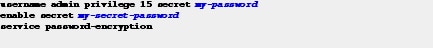
Step 5![]() Configure a local user ID and password to secure access to the switch.
Configure a local user ID and password to secure access to the switch.
We recommend that you encrypt passwords to secure access to the device configuration mode and prevent the display of plain text passwords in configuration files.
Configure Centralized User Authentication Through TACACS+
Note![]() Configuring the TACACS+ protocol is optional and recommended only when using TACACS to manage all of your network devices.
Configuring the TACACS+ protocol is optional and recommended only when using TACACS to manage all of your network devices.
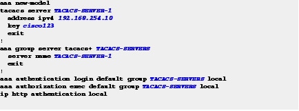
Step 6![]() Configure centralized user authentication through the TACACS+ protocol.
Configure centralized user authentication through the TACACS+ protocol.
As networks increase the number of devices to maintain, there is an operational burden to maintain local user accounts on every device. A centralized authentication, authorization, and accounting (AAA) service reduces operational tasks on each device and provides an audit log of user access for security compliance and root-cause analysis. When AAA is enabled for access control, all management access to the network infrastructure devices (SSH and HTTPS) is controlled by the AAA service.
TACACS+ is the primary protocol used to authenticate management infrastructure devices to determine whether access can be allowed to the AAA server. A local AAA user database defined on each network infrastructure device to provide a fallback authentication source in case the centralized TACACS+ server is unavailable.
This example shows how to configure the switch for TACACS administrative access.
Step 7![]() To save your configuration, use the write memory EXEC command in privileged mode.
To save your configuration, use the write memory EXEC command in privileged mode.

Assign an IP Address to the Switch
Assign an IP to the switch, so that the switch can be managed remotely instead of being restricted to management through a direct connection to the console port.
Although the switch supports multiple IP addresses for switch management, only primary IP address is responsible for switch management.
Two types of IP addresses are used for switch management—in-band and out-of-band.
An in-band IP address is an address assigned to an interface that is reached through the production network. Examples of in-band interfaces that have assigned IP addresses are VLAN, Ethernet, and loopback interfaces.
An out-of-band IP address is an address assigned to an interface that is unreachable through the production network. Out-of-band networks are more common in large network deployments. If you do not have an Out-of-band network, use only an in-band network for management.
On the switch, the out-of-band interface is GigabitEthernet 0/0. The GigabitEthernet 0/0 interface is not connected to the internal switching hardware, but directly to the CPU. IP traffic on GigabitEthernet 0/0 does not use the operating network. If the physical topology of the switch deployment does not support out-of-band, then the switch can be managed with an in-band IP address.
We recommend that the switch be assigned multiple IP addresses for high availability; one IP address on the out-of-band interface, and one on the in-band interface. High availability for switch management ensures that the most available switch on the switch stack is the active switch and that it has a management IP address so that all the stack members are accessible for management. You can have both an in-band and out-of-band IP addresses as long as they are not in the same subnet. The preferred method for management is out-of-band, because it is highly available and less likely to be impacted by DOS and broadcast storms. The GigabitEthernet 0/0 interface on the switch is used for out-of-band management.
Configure the management IP addressees, as described in these sections:
Configure a Management IP Address on an Out-of-Band Interface
Step 8![]() Assign an IP address to an out-of-band interface.
Assign an IP address to an out-of-band interface.

Out-of-band management is managing the switch and all other networking devices through a physical network, which is separate from the production network that carries end-user traffic. To manage the switch with an out-of-band network, the switch uses the GigabitEthernet 0/0 interface. The GigabitEthernet0/0 interface is physically located on the rear of the switch, next to the blue console port.
The following are the advantages of a GigabitEthernet 0/0 interface:
- The interface is not susceptible to network outages, such as broadcast storms or other potential issues on the production network because it is separated from the data plane.
- The interface is out-of-band and allows the switch and all other networking devices to always be manageable so that you can quickly respond whenever there is a network issue.
Step 9![]() Configure a Virtual Routing and Forwarding (VRF) instance.
Configure a Virtual Routing and Forwarding (VRF) instance.
The out-of-band management interface is in its own VRF instance. This means that the routing database and protocol exchange are also separate for this interface from the other data network interfaces.
The following are the limitations of a GigabitEthernet 0/0 interface.
- Management traffic originating from the switch must be associated with the GigabitEthernet 0/0 VRF instance. A Mgmt-vrf is used to segment management traffic from the global routing table of the switch.
- A default route for the Mgmt-vrf is required.

- This interface cannot be used as the source interface for sending SNMP traps. Sending traps to an SNMP trap server requires an IP address on a VLAN interface, see the “Configure a Management IP Address on an In-Band Interface” section.
Note![]() Use the IP address value that you listed in the print-out (Table 3) for the out-of-band management configuration.
Use the IP address value that you listed in the print-out (Table 3) for the out-of-band management configuration.
In the following example, the GigabitEthernet 0/0 interface is not on the switch data plane. This interface (also referred to as the service port) is terminated on the CPU of the switch as opposed to a logical interface of the forwarding ASIC. The GigabitEthernet 0/0 differs from the Ethernet interfaces on the front of the switch because it is only a Layer 3 interface (also referred to as a routable interface). The Ethernet interfaces on the front of the switch default to Layer 2 mode and are used for bridging.
The Ethernet interfaces on the front can be configured to be a routable interface using the no switchport interface command. The GigabitEthernet 0/0 interface will not function without an IP address assigned to it.
Mgmt-vrf is built-in; you do not have to create one for out-of-band management.

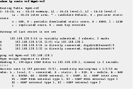
Step 10![]() Following is the example for show ip route vrf command.
Following is the example for show ip route vrf command.
Configure a Management IP Address on an In-Band Interface
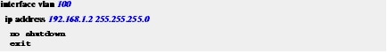
Step 11![]() Assign your management IP address to a VLAN interface that is used only for management, and not used to carry other network traffic.
Assign your management IP address to a VLAN interface that is used only for management, and not used to carry other network traffic.
A VLAN interface is a Layer 3 endpoint on the subnet assigned to the corresponding VLAN.
Note![]() Do not use VLAN 1 as the management VLAN for security purposes.
Do not use VLAN 1 as the management VLAN for security purposes.
The management VLAN is a separate VLAN for managing the switch and all other network devices in the same subnet. You should assign an in-band IP address to a VLAN interface regardless of whether an IP address is assigned to the out-of-band interface.
With in-band management, the IP address can be reached through the production network. For management purposes, the in-band IP address can be used the same way as the out-of-band IP address. There is no functional difference. However, the in-band IP address has more capabilities because this is the source IP address for some of the auto-generated traffic that comes from the switch, for instance, SNMP traps use the in-band IP address.
You can assign an IP address to your VLAN interface before you configure the VLAN on the switch. The VLAN interface is not operational until the VLAN is created in hardware, and at least one physical interface, which is a member of the VLAN, is in a forwarding state.
This example shows a VLAN created for management and indicates that the IP address is reachable.
Note![]() The switch supports IP address assignments to physical Ethernet interfaces that have been configured to operate in Layer 3 mode.
The switch supports IP address assignments to physical Ethernet interfaces that have been configured to operate in Layer 3 mode.
Step 12![]() Configure the default gateway, as shown in the following example. This gateway functions as the default route.
Configure the default gateway, as shown in the following example. This gateway functions as the default route.
When using a VLAN interface, a default route is not required.

Create a Management VLAN in Hardware
Earlier you assigned an IP address to the interface for VLAN 100. Refer to the " Appendix 3, “Configure a Management IP Address on an In-Band Interface” section to assign an IP address to the interface. However, merely assigning the IP address to VLAN 100 does not create the VLAN in hardware. Perform the below step to make the switch reachable through the assigned IP address.
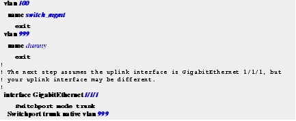
Step 13![]() Configure a management VLAN in hardware and configure an uplink interface as a member of this VLAN.
Configure a management VLAN in hardware and configure an uplink interface as a member of this VLAN.
Note![]() This is an intermediate step required only to make the switch Layer 3 reachable and manageable from SSH or HTTPS as well as the console or Express Setup. You can skip this step if you continue to use the console to complete the configuration, but required if you use another tool to complete the configuration of the switch. The complete best-practice configuration for uplink connectivity is explained in the “Uplink Interface Connectivity” workflow.
This is an intermediate step required only to make the switch Layer 3 reachable and manageable from SSH or HTTPS as well as the console or Express Setup. You can skip this step if you continue to use the console to complete the configuration, but required if you use another tool to complete the configuration of the switch. The complete best-practice configuration for uplink connectivity is explained in the “Uplink Interface Connectivity” workflow.
We recommend that you use a dummy VLAN as the native VLAN on trunk interfaces instead of the default VLAN 1. Because all interfaces are assigned to VLAN 1 by default on the switch, this step limits the traffic associated with potential user configuration and possible connection errors propagating across the trunk.
All other VLANs on the uplink interfaces are tagged with IEEE 802.1q which encapsulates the Layer 2 head of the Frame packet.
The following example shows how to configure VLAN IDs in hardware and assign the names. The upstream interfaces to the switch or router are modified to make them members of the new VLANs. You must have the same VLAN ID on both ends of the Ethernet link to properly configure the management VLAN in hardware. A “dummy” VLAN is used as the native VLAN on trunk interfaces. A dummy VLAN is not used for data or management traffic.
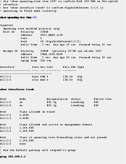
Note![]() The Shortest Path Tree (SPT) and ping command used in this example require that the upstream layer device (switch or router) to be configured to operate in a production network, and without any additional configuration changes being required.
The Shortest Path Tree (SPT) and ping command used in this example require that the upstream layer device (switch or router) to be configured to operate in a production network, and without any additional configuration changes being required.
Note![]() Enter the show running-configuration command to display the initial management information for the switch.
Enter the show running-configuration command to display the initial management information for the switch.
 Feedback