Access Interface Connectivity
This workflow describes how to configure the Ethernet interfaces that connect to the end devices of a switch. End devices are the non-networking devices that connect to the network, such as IP phones, personal computers, wireless access points, printers, and IP cameras. The Ethernet interfaces that connect to end devices are referred to as access interfaces. They differ from uplink interfaces that link to other networking devices.
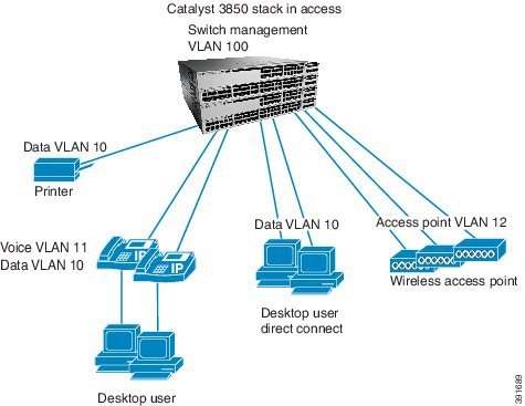
The workflow for configuring access interfaces is based on a switch deployed at the access layer in a campus or branch network (Figure 8). The switch interfaces connected to end devices are the edge of the network, which network security and QoS begins.
Prerequisites for Access Interface Connectivity
- Complete the procedure described in the Global System Configuration workflow, which includes the necessary configurations for the access interface configuration.
- Complete the procedure described in the “Configure QoS on an Uplink EtherChannel Interfaces” workflow, which includes the creation of input services policies for end devices.
Identify Configuration Values
We recommend that you identify certain switch configuration values in advance so that can proceed with this section without interruption. We also recommend that you take a print out of Table 6, and, as you follow the configuration sequence, replace the values in column B with your values in column C.

Note![]() Replace the blue italicized example values with your own values.
Replace the blue italicized example values with your own values.
|
|
|
|
|---|---|---|
QoS service policy input names (See the “Configure QoS on an Uplink EtherChannel Interfaces” section.) |
||
Note![]() Configuration examples begin in global configuration mode, unless noted otherwise.
Configuration examples begin in global configuration mode, unless noted otherwise.
LAN Access Switch Topology with Connections to End Devices
The following illustration shows the topology of LAN Access Switch to end devices:
Figure 8 LAN Access Switch Topology with Connections to End Devices
Configure Access Interface Connectivity
- Recommendations for Configuring an Access Interface
- Configure an Interface for Access Mode
- Configure VLAN Membership
- Create an Interface Description
- Configure Security Features on an Access Interfaces
- Configure QoS on an Access Interface
- Verify Access Interface Configurations
Recommendations for Configuring an Access Interface
Although some end devices do not require the following access interface configurations, we recommend that you perform them to ensure consistency. The configurations do not interfere with the operation of the network or the attached end device, and is considered safe to use.
When configuring your access interface, you should complete the following tasks:
IP Device Tracking

Note![]() Symptoms as a result of IPDT issues are seen on the end device. For instance on Windows PC, an error message report for a duplicate IP Address 0.0.0.0 appears.
Symptoms as a result of IPDT issues are seen on the end device. For instance on Windows PC, an error message report for a duplicate IP Address 0.0.0.0 appears.
IPDT is enabled globally, but it cannot be globally disabled. To disable IPDT, you must disable it at the interface level.
Note![]() To disable IPDT on a port channel, you must first unbundle the physical Ethernet interfaces from the port channel.
To disable IPDT on a port channel, you must first unbundle the physical Ethernet interfaces from the port channel.
We recommend that you disable IPDT on all access interfaces except under these situations where a feature explicitly has IPDT enabled:
- IPDT is required for Centralized Web Authentication with Identity Services Engine (ISE).
- Network Mobility Services communicates with the Mobility Services Engine to track location.
- Device Sensor watches the control packets that ingress from the attached end device and determine what type of device is attached. Device Sensor uses multiple sources (such as IPDT) to determine the device type. Device Sensor is critical to other features, such as Auto Smart Ports, and AutoConf.
- Auto Smart Ports and AutoConf are indirectly affected, because they are clients of Device Sensor. The Device Sensor feature uses IPDT to aid in detection of attached device types.
- Address Resolution Protocol (ARP) snooping will be impacted if IPDT is disabled.
Recommended ways to disable IPDT at the interface levels:

Alternately, you can use the following method:

Configure an Interface for Access Mode
Step 1![]() Use the switchport host command to perform the following configurations for the end devices on your switch:
Use the switchport host command to perform the following configurations for the end devices on your switch:
- Configure the access interface for static access mode, which is single VLAN mode with no negotiation.
- Configure the interface for Spanning Tree PortFast (STPF), which shortens the time it takes for the interface to go into forwarding mode. We recommend STPF on interfaces that do not connect to other bridging devices (Ethernet switches).
The default Administrative mode for Ethernet interfaces on a switch is dynamic auto. Dynamic mode means the interface will negotiate to trunk mode if the networking device on the side of the link initiates the negotiation to trunk (administrative mode “dynamic desirable”).
Configure VLAN Membership
Step 2![]() Configure the VLANs for voice and data traffic.
Configure the VLANs for voice and data traffic.
VLAN configuration on an interface is dependent on the end device being used:
- IP phones, IP cameras, and access points are typically configured on separate VLANs.
- VLANs 10 and 11 are defined as the data and voice VLANs, respectively.
Recommendation: Do not use VLAN 1 for data or voice. VLAN 1 is the default VLAN on the 3850. This is well documented and understood by experienced networking personnel. Thus VLAN 1 will be more susceptible to attacks. Changing the VLAN IDs to something other than VLAN1 has been a long standing Cisco recommendation for Ethernet switching

Create an Interface Description
Step 3![]() Create a description for the interface to identify the end-device type.
Create a description for the interface to identify the end-device type.

Tip![]() When you create an interface description, you can quickly scan a long list of interfaces to learn how they are used in your network.
When you create an interface description, you can quickly scan a long list of interfaces to learn how they are used in your network.

Configure Security Features on an Access Interfaces
Step 4![]() Enable port security features to protect the network from malicious or troublesome end devices.
Enable port security features to protect the network from malicious or troublesome end devices.
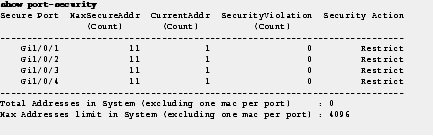
The primary purpose of port security is to prevent an end device from overloading the switch with too many source MAC addresses. Port security controls the MAC addresses remembered from the attached network device. Port security controls how many MAC addresses are remembered, how long they are remembered, and what happens when too many are remembered.
The MAC address limit is 11. When the end device exceeds 11 source MAC addresses, the ingress traffic to the switch on those source MAC addresses is dropped.

Note![]() MAC addresses that are remembered on interfaces with port security do not appear in the dynamic MAC address table; they appear in the static MAC address table.
MAC addresses that are remembered on interfaces with port security do not appear in the dynamic MAC address table; they appear in the static MAC address table.
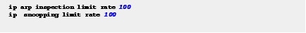
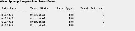
Step 5![]() Configure IP ARP inspection and (DHCP, IGMP, and so on) snooping to 100 p/s on the interface. (Incoming ARP packets exceeding 100 p/s is not typical and is considered malicious. Those packets are dropped and a syslog message is raised).
Configure IP ARP inspection and (DHCP, IGMP, and so on) snooping to 100 p/s on the interface. (Incoming ARP packets exceeding 100 p/s is not typical and is considered malicious. Those packets are dropped and a syslog message is raised).
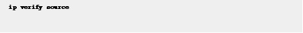
Step 6![]() Configure IP source guard to prevent IP address spoofing on the interface.
Configure IP source guard to prevent IP address spoofing on the interface.
Step 7![]() Enable storm control on broadcast and multicast packets on the interface to protect the network from a flood of broadcast or multicast packets.
Enable storm control on broadcast and multicast packets on the interface to protect the network from a flood of broadcast or multicast packets.
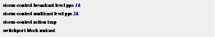
When the configured levels are exceeded, the switch sends an SNMP trap. The interfaces are not put into a disabled state.
Unicast packets are blocked on egress and not ingress traffic. The switch drops unknown unicast packets from being egressed to the end device, ensuring that only the packets intended for the end device are forwarded.
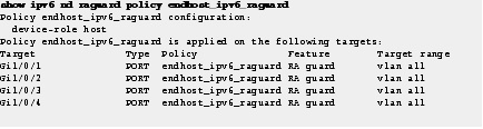
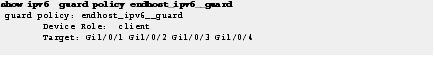
Step 8![]() Configure IPv6 security on the interface to secure the end devices from malicious or unexpected operation by preventing them from transmitting IPv6 router advertisements, and IPv6 responses.
Configure IPv6 security on the interface to secure the end devices from malicious or unexpected operation by preventing them from transmitting IPv6 router advertisements, and IPv6 responses.
The applied policies are defined in the “Global System Configuration” workflow.

Configure QoS on an Access Interface
Quality of Service (QoS) provides preferential treatment to certain types of traffic at the expense of others. Without QoS, the switch offers best-effort service to each packet, regardless of the packet contents or size. It sends the packets without any assurance of reliability, delay bounds, or throughput.
Aut0 QoS on the switch generates multiple service policies for various end devices. The service policy that is generated depends with the end device type.
Step 9![]() Apply service policies to a single access interface.
Apply service policies to a single access interface.
The switch then automatically generates the modular QoS command-line interface (MQC) service policies needed for access.
This example identifies some of the service policy configurations.
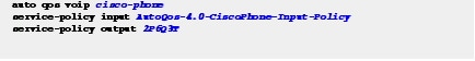
Step 10![]() Apply ingress and egress service policies.
Apply ingress and egress service policies.
Check the end device-specific configuration to see which service policy is recommended for an end device.
Verify Access Interface Configurations
This following section describes the commands that you should use to use to confirm that your configurations in this workflow are correctly applied to your switch:
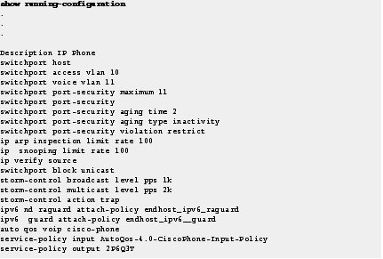
Step 11![]() Use the show running-configuration command to verify the operational configuration of the access interfaces.
Use the show running-configuration command to verify the operational configuration of the access interfaces.
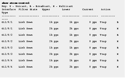
Use the show storm-control command to confirm that the interfaces are configured for storm control.
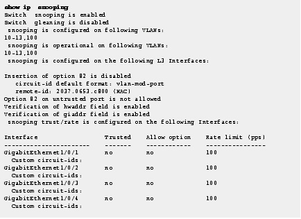
Use the show ip snooping command to confirm that the interfaces are configured for snooping.
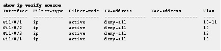
Use the show ip verify source command to confirm that the IP source guard is configured and working.
Use the show port-security command to confirm that access interfaces are configured for port security.
Use the show ip arp inspection interfaces command to confirm the rate and untrusted state of access interfaces.
Use the show ipv6 nd raguard policy command to confirm that access interfaces are configured for Router Advertisement Guard with specific policies.
Use the show ipv6 guard policy command to confirm the guard on access interfaces.
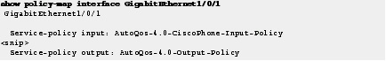
Use the show policy-map interface command to confirm the input and output service policies applied to access interfaces.
Display Running Configuration for Access Interface Connectivity
Step 1![]() Show the recommended configuration for each end device type described in the beginning of this workflow.
Show the recommended configuration for each end device type described in the beginning of this workflow.
Tip![]() To use the same interface configuration for multiple interfaces on the switch, use the interface range command. This command allows you to issue a command once and have it apply to many interfaces. Because most of the interfaces in the access layer are configured identically, using this command can save a lot of time. For example, the following command allows you to enter commands simultaneously on all 48 interfaces (GigabitEthernet 1/0/1 to GigabitEthernet 1/0/48).
To use the same interface configuration for multiple interfaces on the switch, use the interface range command. This command allows you to issue a command once and have it apply to many interfaces. Because most of the interfaces in the access layer are configured identically, using this command can save a lot of time. For example, the following command allows you to enter commands simultaneously on all 48 interfaces (GigabitEthernet 1/0/1 to GigabitEthernet 1/0/48).

Note Apply the interface range command to every switch stack member. This range command will work for all interfaces on a single switch member. Enter the range command for each member.
The following example displays the IP phone Access Interface information:
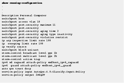
Personal Computer Access Interface
The following example displays the Personal Computer access interface information.
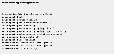
Lightweight Access Point Access Interface
The following example displays the Lightweight Access Point Access interface information:
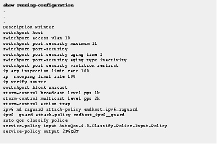
The following example displays the Printer Access Interface information.
 Feedback