- Prerequisites for Global System Configuration
- Identify Configuration Values
- Assign Global Configuration Information
- Configure High Availability on the Switch Stack
- Configure the Switch to run in VTP Transparent Mode
- Enable Rapid Per-VLAN Spanning Tree Plus
- Configure BPDU Guard for Spanning-Tree PortFast Interfaces
- Configure UDLD to Detect Link Failure
- Configure an Access List to Limit Switch Access
- Configure System Clock and Console Timestamps
- Configure DHCP Snooping Security Features
- Configure ARP Inspection
- Configure EtherChannel Load Balancing
- Create Access Layer VLANs
- Create IPv6 First-Hop Security Policies
- Increase the TFTP Block Size
- Enable New Members to Automatically Update to the Switch Stack Image
Global System Configuration
This workflow describes common global configurations for all switch deployments in the access layer.
Prerequisites for Global System Configuration
- Complete the task described in “Initial Switch Configuration” workflow.
- If you have not completed the task described in the “Uplink Interface Connectivity” workflow, the switch might not be IP reachable. If that is the case, use only the switch console to perform the Global System Configuration workflow.
If you have completed the “Uplink Interface Connectivity” workflow, you can perform the Global System Configuration workflow using the switch console, SSH, or any management tool. Using tools other than the console requires you to log in using user names and passwords configured, as described in the section the “Initial Switch Configuration” workflow.
Identify Configuration Values
We recommend that you identify certain switch configuration values in advance so that you can proceed with this workflow without interruption. We recommend that you take a print out of Table 4, and, as you follow the configuration sequence, you should replace the values in column B with your values in column C.

Note![]() Replace the blue italicized example values with your own values.
Replace the blue italicized example values with your own values.
Note![]() Configuration examples begin in global configuration mode, unless noted otherwise.
Configuration examples begin in global configuration mode, unless noted otherwise.
Assign Global Configuration Information
Note![]() The following tasks should be performed in the same sequence in which they are listed here.
The following tasks should be performed in the same sequence in which they are listed here.
- Configure High Availability on the Switch Stack
- Configure the Switch to run in VTP Transparent Mode
- Enable Rapid Per-VLAN Spanning Tree Plus
- Configure BPDU Guard for Spanning-Tree PortFast Interfaces
- Configure UDLD to Detect Link Failure
- Configure an Access List to Limit Switch Access
- Configure System Clock and Console Timestamps
- Configure DHCP Snooping Security Features
- Configure ARP Inspection
- Configure EtherChannel Load Balancing
- Create Access Layer VLANs
- Create IPv6 First-Hop Security Policies
- Increase the TFTP Block Size
- Enable New Members to Automatically Update to the Switch Stack Image
Configure High Availability on the Switch Stack
Step 1![]() Assign the active switch and standby switch with high stack-member priority values, so that network operations are not affected during a stack-member failure.
Assign the active switch and standby switch with high stack-member priority values, so that network operations are not affected during a stack-member failure.
Recommendation: For consistency, configure the stack-member priority used to determine the active stack member. By configuring one member to be the active stack member, you ensure that this member is always the active member through all stack elections, for the lifetime of the stack. The member with the highest configured priority becomes the active member.
In a switch stack, the member most likely to fail is the active member. Therefore, in a switch stack with three or more members, we recommend that you configure uplink connectivity on more than one stack member and do not configure uplink connectivity on the active member. This way, uplink connectivity is not affected if the active member fails.
In this document, the stack refers to a two-member stack, and the example here shows how to assign the highest priority to member 1. Assign a secondary member by giving it a slightly lower priority. The default priority is 1.

Note![]() For additional information about managing switch stacks and configuring high availability features on the switch, see the Stack Manager and High Availability Configuration Guide, Cisco IOS XE Release.
For additional information about managing switch stacks and configuring high availability features on the switch, see the Stack Manager and High Availability Configuration Guide, Cisco IOS XE Release.
Configure the Switch to run in VTP Transparent Mode
Step 2![]() Configure your switch to run in VTP transparent mode in order to avoid the VLAN configuration updates coming from the network, since they have the potential for unexpected behavior due to error operations.
Configure your switch to run in VTP transparent mode in order to avoid the VLAN configuration updates coming from the network, since they have the potential for unexpected behavior due to error operations.
Typically, VLANs are defined once during your initial switch configuration and do not require continuous VTP updates after the switch is operational.
A switch in VTP transparent mode can create, modify, and delete VLANs (the same way as VTP servers), but the switch does not send dynamic propagation of VLAN information across the network and does not synchronize its VLAN configuration based on advertisements received. Configuration changes made when the switch is in this mode are saved in the switch’s running configuration, and can be saved to the switch’s startup configuration file.
Note![]() The default VTP mode for the switch is VTP server mode. This mode allows you to create, modify, and delete VLANs and specify other configuration parameters for the entire VTP domain. VTP servers advertise their VLAN configuration to other switches in the same VTP domain and synchronize their VLAN configuration with other switches based on advertisements received over trunk links.
The default VTP mode for the switch is VTP server mode. This mode allows you to create, modify, and delete VLANs and specify other configuration parameters for the entire VTP domain. VTP servers advertise their VLAN configuration to other switches in the same VTP domain and synchronize their VLAN configuration with other switches based on advertisements received over trunk links.

Enable Rapid Per-VLAN Spanning Tree Plus
Step 3![]() Enable Rapid Per-VLAN Spanning Tree Plus (PVST+), to improve the detection of indirect failures or linkup restoration events over classic spanning tree.
Enable Rapid Per-VLAN Spanning Tree Plus (PVST+), to improve the detection of indirect failures or linkup restoration events over classic spanning tree.
Rapid PVST+ provides an instance of RSTP (IEEE 802.1w) for each VLAN, and PVST+ improves the detection of indirect failures or linkup restoration events over the classic spanning tree (IEEE 802.1D).
Recommendation: Enable spanning tree even if your deployment is created without any Layer 2 loops. By enabling spanning tree, you ensure that if physical or logical loops are accidentally configured, no actual Layer 2 loops occur.

Configure BPDU Guard for Spanning-Tree PortFast Interfaces
Step 4![]() Configure the Bridge Protocol Data Unit (BPDU) guard globally to protect all Spanning-Tree PortFast-enabled interfaces.
Configure the Bridge Protocol Data Unit (BPDU) guard globally to protect all Spanning-Tree PortFast-enabled interfaces.
The BPDU guard protects against a user plugging a switch into an access port, which many cause a catastrophic, undetected spanning-tree loop.
If a Spanning-Tree PortFast-configured interface receives a BPDU, an invalid configuration exists, such as the connection of an unauthorized device. The BPDU Guard feature prevents loops by moving a nontrunking interface into an errdisable state when a BPDU is received on an interface when STPF is enabled.
The BPDU configuration protects STPF-enabled interfaces by disabling the port if another switch is plugged into the port.
This command should configured globally, not at the interface level.

Configure UDLD to Detect Link Failure
Step 5![]() Configure Unidirectional Link Detection (UDLD) in aggressive mode, not normal mode.
Configure Unidirectional Link Detection (UDLD) in aggressive mode, not normal mode.
UDLD detects a unidirectional link, and then disables the affected interface and alerts you. Unidirectional links can cause a variety of problems, including spanning-tree loops, black holes, and nondeterministic forwarding. In addition, UDLD enables faster link-failure detection and quick reconvergence of interface trunks, especially with fiber, which can be susceptible to unidirectional failures.

In aggressive mode, if the link state of a port is determined to be bidirectional and the UDLD information times out while the link on the port is still in UP state, UDLD tries to re-establish the state of the port. If this not successful, the port is put into errdisable state. In normal mode, the port state for UDLD is marked as undetermined, and operates according to its Spanning Tree Protocol state.
Do not change UDLD aggressive timers.
Note![]() UDLD in aggressive mode is not needed when the upstream device is a switch operating in VSS mode.
UDLD in aggressive mode is not needed when the upstream device is a switch operating in VSS mode.
For more information about VSS-enabled campus design, see the Campus 3.0 Virtual Switching System Design Guide.
Configure an Access List to Limit Switch Access
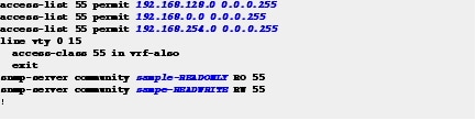
Step 6![]() If your network operation support is centralized, you can increase network security by using an access list to limit the networks that can access your switch.
If your network operation support is centralized, you can increase network security by using an access list to limit the networks that can access your switch.
We recommend that you use an access list to permit IP addresses from known source management locations.
In this example, only the hosts on the 192.168.128.0, 192.168.0.0, and 192.168.254.0 networks can access your switch using SSH or SNMP. The following example shows an ACL that permits three subnets. your network may have more subnets or fewer subnets. configure the ACL that best fits your network. You can continue to add to the list, as required for your network deployment.
Configure System Clock and Console Timestamps
Step 7![]() Configure a synchronized clock by programming your network devices to synchronize to a local NTP server in the network.
Configure a synchronized clock by programming your network devices to synchronize to a local NTP server in the network.
The local NTP server typically references a more accurate clock feed from an outside source.
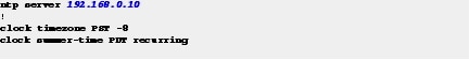
Step 8![]() Configure console messages, logs, and debug output to provide timestamps on output, which allows cross-referencing of events in a network.
Configure console messages, logs, and debug output to provide timestamps on output, which allows cross-referencing of events in a network.

Configure DHCP Snooping Security Features
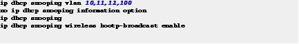
Step 9![]() Enable Dynamic Host Configuration Protocol (DHCP) snooping on the data, voice, and wireless AP VLANs.
Enable Dynamic Host Configuration Protocol (DHCP) snooping on the data, voice, and wireless AP VLANs.
The switch intercepts and safeguards DHCP messages within the VLAN. This configuration ensures that an unauthorized DHCP server cannot allocate addresses to end-user devices.
Configure ARP Inspection
ARP inspection is a security feature that prevents ARP spoofing.
Step 10![]() Enable Address Resolution Protocol (ARP) inspection on the data, voice, and management VLANs.
Enable Address Resolution Protocol (ARP) inspection on the data, voice, and management VLANs.

Configure EtherChannel Load Balancing
Step 11![]() Set EtherChannels to use the traffic source and destination IP address when calculating which link to send traffic to.
Set EtherChannels to use the traffic source and destination IP address when calculating which link to send traffic to.
EtherChannel traffic should be balanced across all physical interfaces. The default load-balancing scheme for EtherChannels is based on the source MAC address.
This configuration normalizes the method in which traffic is load-shared across the member links of an EtherChannel. EtherChannels are used extensively in this design because of their resilience.

Create Access Layer VLANs
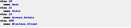
Step 12![]() Create VLANs to separate traffic based on end-user devices.
Create VLANs to separate traffic based on end-user devices.
When VLANs are created, they automatically join any interface that is configured for trunk mode. Earlier, the uplink interface was configured for trunk mode. Therefore, the uplink interface should now be a member of these VLANs.
Use consistent VLAN IDs and VLAN names in the access layer. Consistent IDs and names help with consistency, and network operation becomes more efficient.
Note![]() Use VLAN 200 for wireless clients only if the switch operates as a wireless controller in the converged access mode.
Use VLAN 200 for wireless clients only if the switch operates as a wireless controller in the converged access mode.
Create IPv6 First-Hop Security Policies
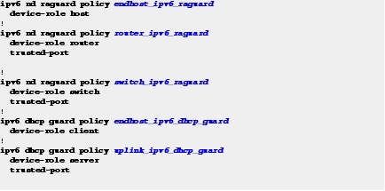
Step 13![]() Create and apply global IPv6 security policies on the uplink interfaces to define the trust and roles on the connected distribution switches or routers.
Create and apply global IPv6 security policies on the uplink interfaces to define the trust and roles on the connected distribution switches or routers.
Blocking router advertisements with Router Advertisement Guard and DHCP responses from untrusted sources are an easy way to secure against the most common IPv6 problems.
Note![]() Access interfaces to end devices should not be trusted for router advertisements and IPv6 DHCP response.
Access interfaces to end devices should not be trusted for router advertisements and IPv6 DHCP response.
This example configuration shows how to create global policies that are applied to the interfaces described in the “Access Control on the Wired Network” workflow.
Increase the TFTP Block Size
Step 14![]() Increase the TFTP block size to the maximum allowed value of 8192.
Increase the TFTP block size to the maximum allowed value of 8192.
By default, the switch uses a TFTP block size value of 512, which is the lowest possible value. Increasing this global value significantly improves the TFTP file transfer time.

Enable New Members to Automatically Update to the Switch Stack Image
Step 15![]() Enable the Auto Upgrade feature so that new switch members automatically update to the Cisco IOS version that is running on the switch stack.
Enable the Auto Upgrade feature so that new switch members automatically update to the Cisco IOS version that is running on the switch stack.
When new members join an existing switch stack, the Cisco IOS version of the new members must match the Cisco IOS version of the existing members. The Auto Upgrade feature provides the ability to automatically update new members when they join. However, this feature is not enabled by default.
Note![]() The switch stack must be running Cisco IOS XE Release 3.3.1 or higher, or later in install mode.
The switch stack must be running Cisco IOS XE Release 3.3.1 or higher, or later in install mode.

For detailed information about the Auto Upgrade feature, see the Using the Auto-Upgrade feature on the Cisco Catalyst 3850 document.
 Feedback