- Prerequisites for Uplink Interface Connectivity
- Restrictions for Uplink Interface Connectivity
- Identify Configuration Values
- LAN Access Switch Topology with Uplinks to a Distribution Switch or Distribution Router
- Configure Uplink Interface Connectivity
- Recommendations for Configuring an Uplink Interface to a Router or Switch
- Configure QoS on an Uplink EtherChannel Interfaces
- Configure an Uplink Interface as an EtherChannel and as a Trunk
- Configure Security Features on an Uplink EtherChannel Interface
- Spanning-Tree Recommendations for an Uplink Interface Connecting to a Distribution Switch
- Verify Uplink Interface Configurations
- Display Uplink Interface Connectivity for the Switch
Uplink Interface Connectivity
This workflow describes how to configure the Ethernet interfaces that connect a switch or switch stack to distribution switches or routers. These interfaces are uplink interfaces. They are different from access interfaces that connect to non-networking end devices such as IP phones, personal computers, wireless access points, printers, and IP cameras.
The switch interface configuration recommendations are based on a switch stack deployed in the campus or branch of the access layer.
When stacking two or more physical switches into one logical switch, we recommend that the uplink interfaces are configured across the physical members to ensure that an active uplink interface always available for switch-stack members.
Prerequisites for Uplink Interface Connectivity
Ensure that the best-practice configurations are set, as described in the Global System Configuration workflow.
Restrictions for Uplink Interface Connectivity
- A maximum of only eight physical links can be active in a single EtherChannel group.
- All the ports in an EtherChannel must be assigned to the same VLAN, or must be configured as trunk ports.
- All the interfaces in an EtherChannel must be of the same type, for example, Gigabit Ethernet interfaces cannot be mixed with 10-Gbps interfaces.
Identify Configuration Values
We recommend that you identify certain switch configuration values in advance so that you can proceed with this workflow without interruption. We recommend that you take a print out of Table 5, and, as you follow the configuration sequence, replace the values in column B with your values in column C.

Note![]() Replace the blue italicized example values with your own values.
Replace the blue italicized example values with your own values.
|
|
|
|
|---|---|---|
Note![]() Configuration examples begin in global configuration mode, unless noted otherwise.
Configuration examples begin in global configuration mode, unless noted otherwise.
LAN Access Switch Topology with Uplinks to a Distribution Switch or Distribution Router
The following illustration displays the LAN Access Switch Topology with Uplinks to a distribution switch or distribution router:
Figure 6 LAN Access Switch Topology with Uplinks to a Distribution Switch
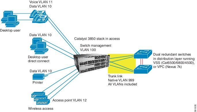
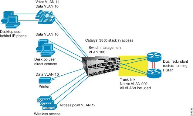
Figure 7 Uplinks for a Distribution Router
Configure Uplink Interface Connectivity
- Recommendations for Configuring an Uplink Interface to a Router or Switch
- Configure QoS on an Uplink EtherChannel Interfaces
- Configure an Uplink Interface as an EtherChannel and as a Trunk
- Configure Security Features on an Uplink EtherChannel Interface
- Spanning-Tree Recommendations for an Uplink Interface Connecting to a Distribution Switch
- Verify Uplink Interface Configurations
Recommendations for Configuring an Uplink Interface to a Router or Switch
When configuring your uplink interface, follow the below recommendations to guide you through the configuration from interface to upstream router or switch:
- Make sure that the uplink connections from the switch stack to the distribution switches have enough bandwidth to carry the traffic associated with all of the access interfaces on the switch stack.
- Use EtherChannels to increase resilience of in case an uplink interface fails.
- For EtherChannels, use Link Aggregation Control Protocol (LACP) active-active mode, which adheres to the IEEE 802.3ad standard. The active-active mode implies that both the switch stack as well as the distribution switch side of the EtherChannel must be configured in LACP active mode.
- Use uplink ports on the different switches in the switch stack to connect back to the distribution switches. This configuration ensures that there is no single source of failure for the switch stack. If a switch in the stack owning one of the uplink connections fails, there will still be an uplink port connection from a remaining member of the switch stack connecting back to the distribution switches.
- All the interfaces are assigned to VLAN 1 by default. Do not configure VLAN 1 on the trunk; this is to prevent traffic associated with potential user connection errors from propagating across the trunk.
Configure QoS on an Uplink EtherChannel Interfaces
Note![]() This configuration should be applied to the physical uplink interfaces before adding them to an EtherChannel.
This configuration should be applied to the physical uplink interfaces before adding them to an EtherChannel.
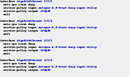
Step 1![]() Apply the Trust Differentiated Services Code Point (DSCP) service policy on an interface in the ingress direction, and then apply the 2P6Q3T policy in order to ensure proper congestion management and egress bandwidth distribution on the interface in the egress direction.
Apply the Trust Differentiated Services Code Point (DSCP) service policy on an interface in the ingress direction, and then apply the 2P6Q3T policy in order to ensure proper congestion management and egress bandwidth distribution on the interface in the egress direction.
Ethernet traffic that is received from the upstream switch or router contains trusted QoS markings and is classified to guarantee a type of service.
Additional service policies should be applied after traffic is transmitted in order to ease congestion. For more information see, Configure QoS on an Access Interface
Configure an Uplink Interface as an EtherChannel and as a Trunk
Step 1![]() Choose one of the following configurations based on your network topology:
Choose one of the following configurations based on your network topology:
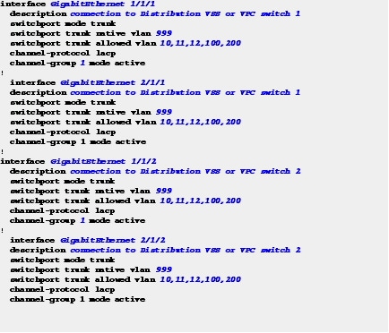
Configure an Uplink Interface to Connect to a Distribution VSS or VPC Switch
1.![]() Ensure that the distribution Virtual Switch System (VSS) or Virtual Port Channel (VPC) switch connections are configured the same way and that the EtherChannel is configured in LACP active mode.
Ensure that the distribution Virtual Switch System (VSS) or Virtual Port Channel (VPC) switch connections are configured the same way and that the EtherChannel is configured in LACP active mode.
2.![]() For additional resilience, ensure that the uplink interfaces are located on different switches in the switch stack.
For additional resilience, ensure that the uplink interfaces are located on different switches in the switch stack.
Figure 6, shows the switch stack that has a single EtherChannel connection to a distribution VSS or VPC switch pair.
The VSS and VPC systems have an explicit configuration between the Cisco distribution switch pair. That allows them to act as a single logical switch when connected to the EtherChannel. The EtherChannel is configured as a trunk with VLANs 10, 11, 12, and 100, with the native VLAN set to 999.
Note![]() Use this switch-stack uplink interface configuration only when connecting the switch stack to a VSS or VPC distribution switch pair, and not when the distribution switch pair is configured as two standalone switches.
Use this switch-stack uplink interface configuration only when connecting the switch stack to a VSS or VPC distribution switch pair, and not when the distribution switch pair is configured as two standalone switches.
Configure an Uplink Interface to Connect to a Distribution Router (or Standalone Distribution Switch)
Note![]() Use this configuration when connecting the switch stack to two standalone distribution switches (not configured as a VSS or VPC pair). However, do not use the spanning-tree portfast trunk command for switch configuration.
Use this configuration when connecting the switch stack to two standalone distribution switches (not configured as a VSS or VPC pair). However, do not use the spanning-tree portfast trunk command for switch configuration.
- Ensure that the distribution VSS or VPC router side of the connections are configured the same and that the EtherChannel is configured with the LACP active mode.
- For additional resilience, the configured uplink interfaces should be located on different switches in the switch stack.
- Use the spanning-tree portfast trunk command to allow the switch side of the uplink to immediately transition to a spanning-tree forwarding state when the link becomes available, because routers do not participate in a spanning tree.
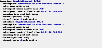
Figure 7 shows a switch stack having a separate EtherChannel to each distribution router. Each EtherChannel is configured as a trunk with VLANs 10, 11, 12, 100, 200, and 999, with the native VLAN set to 999.
EtherChannel Connection to Router 1
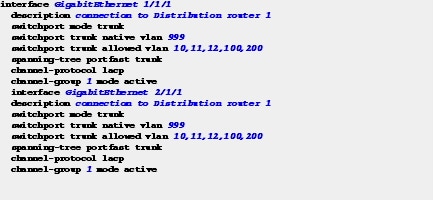
EtherChannel Connection to Router 2
Configure Security Features on an Uplink EtherChannel Interface
Step 2![]() Configure IPv4 and IPv6 security features on uplink EtherChannel interfaces.
Configure IPv4 and IPv6 security features on uplink EtherChannel interfaces.
The uplink EtherChannel interfaces to distribution routers and switches should be configured to trust router advertisements and IP response, because Layer 3 routing and server functionality resides on the distribution switches and routers. This step is different from the access interface-to-end device configuration, which should not be trusted, as specified in the “Access Interface Connectivity” workflow.
The policies that should be applied are defined in the “Global System Configuration” workflow.
In the following example, security is applied to the uplink interfaces connecting to VPC, VSS, or standalone switch.

In the following example, security is applied to the uplink interfaces connecting to routers:

Spanning-Tree Recommendations for an Uplink Interface Connecting to a Distribution Switch
Note![]() Complete this configuration on the distribution switches and not on the switch. The recommendations listed below are not applicable when routers are used at the distribution layer.
Complete this configuration on the distribution switches and not on the switch. The recommendations listed below are not applicable when routers are used at the distribution layer.
Step 3![]() On uplink interfaces to distribution switches (Figure 6), ensure that the spanning-tree root for the switch-stack VLANs is configured on the distribution switch pair.
On uplink interfaces to distribution switches (Figure 6), ensure that the spanning-tree root for the switch-stack VLANs is configured on the distribution switch pair.
Follow the below recommendations when the standalone distribution switches are used instead of a VSS or VPC system:
- Make sure that the spanning-tree roots for the VLANs are distributed evenly between two standalone distribution switches. For example, configure one switch as the spanning-tree root for all the even VLANs, and configure the other switch as the spanning-tree root for all the odd VLANs. This distribution configuration ensures that the spanning tree does not block all the VLANs on a single uplink interface, and results in an even traffic flow on the uplink interfaces.
- If Hot Standby Router Protocol (HSRP) or Virtual Router Redundancy Protocol (VRRP) is configured for the VLANs located on the standalone distribution switches, make sure that the VLAN configuration on the active switch is the same on the switch that is the spanning-tree root for that VLAN.
- Avoid flooding of traffic caused by asymmetric routing of traffic flows, by configuring the arp timeout interface configuration command. This command adjusts the ARP aging timer to less than the MAC address table aging timer on the Layer 3 VLAN interfaces of the distribution switches. By default, the MAC address table aging timer is set to 5 minutes (300 seconds) on the switch.
For more information about spanning tree root configuration on the VSS, see the “Spanning Tree Configuration Best Practice with VSS” section of the VSS Enabled Campus Design Guide.
For more information about spanning-tree root on distribution switches, see the “Spanning VLANs across Access Layer Switches” section of the Campus Network for High Availability Design Guide.
For more information about spanning-tree root configuration and asymmetric routing, see the “Spanning VLANs Across Access Layer Switches” and “Asymmetric Routing and Unicast Flooding” sections of the Campus Network for High Availability Design Guide.
Verify Uplink Interface Configurations
Use the following commands to verify if configurations in this workflow are correctly applied to your uplink interfaces:
Display Uplink Interface Connectivity for the Switch
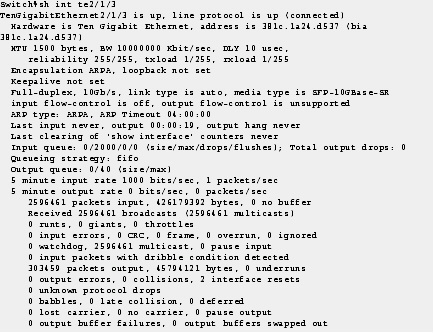
Step 1![]() Enter the show running-configuration command to display uplink interface connectivity for the switch.
Enter the show running-configuration command to display uplink interface connectivity for the switch.
 Feedback