Ease of Deployment
This document describes best practices for deploying your Cisco Catalyst 3850 Series and Cisco Catalyst 3650 Series switches.

Note![]() Unless otherwise noted, the term switch refers to a standalone Catalyst 3850 switch, a Catalyst 3650 switch, or a switch stack.
Unless otherwise noted, the term switch refers to a standalone Catalyst 3850 switch, a Catalyst 3650 switch, or a switch stack.
A Cisco switch deployment best practice is a preferred configuration method to employ on your Catalyst switches. It is a proven and tested way to improve network security, performance, and availability.
A best practice configuration includes an explanation of why you should perform a given task and a sample snapshot of a full running configuration that you can extrapolate for your specific scenario.

Tip![]() Use the configuration recommendations in this document as a template for your switch deployments.
Use the configuration recommendations in this document as a template for your switch deployments.
Note![]() Many Cisco documents are available that define best practices for a variety of features and solutions. There will be some overlap between the information provided in this guide and other best practices and deployment guides. When relevant, this document references other existing documents so the reader can get a deeper understanding of an aspect of the 3850 operation. Otherwise, this document is self-contained, and provides complete best practice configuration.
Many Cisco documents are available that define best practices for a variety of features and solutions. There will be some overlap between the information provided in this guide and other best practices and deployment guides. When relevant, this document references other existing documents so the reader can get a deeper understanding of an aspect of the 3850 operation. Otherwise, this document is self-contained, and provides complete best practice configuration.
Configuration Tool
The configuration examples in this document use the Cisco IOS CLI configuration tool, which is the most common tool used to configure a switch.
However, you do have the flexibility to use a different tool to perform switch configuration. Other configuration tools are the Express Setup, Device Manager, and Cisco Prime.
The examples provided in this document show the CLI commands that you should execute on your switch. You must replace the blue italicized example values with your own values.

LAN Access Switch Topology
The workflows described in this document assume that a switch is deployed as a LAN access switch. Unless noted otherwise, a switch that is in the LAN access layer is configured as a Layer 2 switch, with all Layer 3 services provided by the directly connected distribution switch or router.
This document assumes that the switches are stacked together to form a switch stack (a common switching unit). We recommend that you use switch stacks because of built-in redundancy. We also recommend the use of using switch stacks when deploying switches in converged access mode (wireless mode) and connecting access points to different stack members.
A switch deployed at the LAN access layer provides high-bandwidth connections to devices through 10/100/1000 Ethernet, with both Gigabit and 10-Gigabit uplink connectivity options.
When a switch is deployed in access mode, it enables end devices, such as IP phones, wireless access points, and desktops to gain access to the network. The Power over Ethernet (PoE) switch models support PoE+ (30 W) and UPoE (60 W) to power IP phones, wireless access points, and IP cameras. The field-replaceable uplink module from the switch enables different uplink connectivity types.
Figure 1 shows an enterprise campus deployment, where the switch is connected to a distribution layer switch (such as a Catalyst 6500,6800,4500 or a Nexus 7000 switch).
Figure 1 LAN Access Switch Topology with Distribution Switch
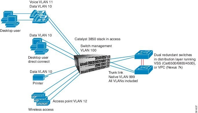
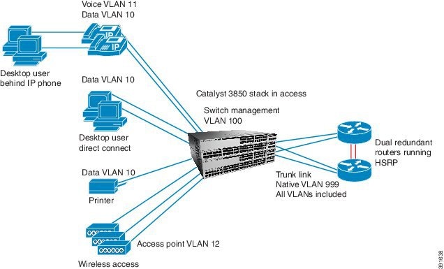
Figure 2 shows a branch deployment, where the switch is connected to a router (ISR). Because the switch operates as a Layer 2 switch, not many differences occur in the configuration between the campus or branch deployment cases. Differences in the configuration are noted in the best practice procedures.
Figure 2 LAN Access Switch Topology with Distribution Router
Cisco Catalyst Switch Configuration Workflow
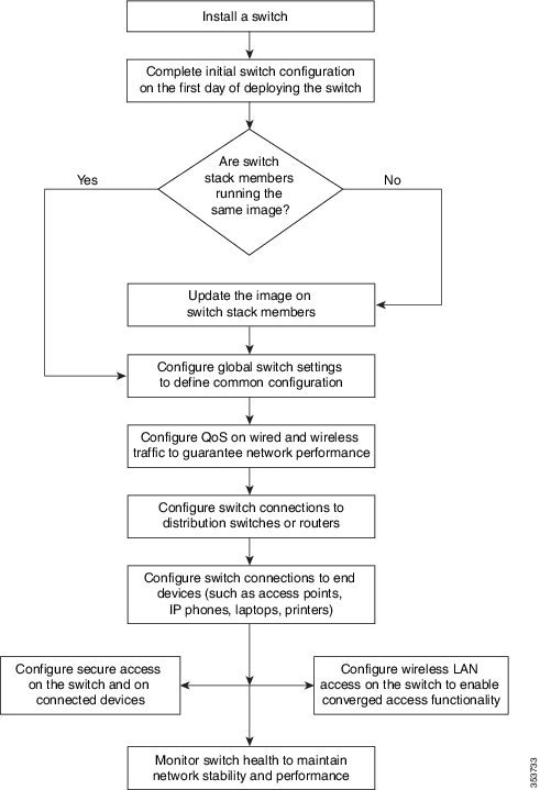
This document focuses on configuring a switch network and is organized in a workflow pattern, beginning with the initial configuration of a switch after it is racked, mounted, connected, and powered on, and ending with monitoring system health.
Figure 3 shows the best-practice configurations described in this document.
See the Switch Hardware Installation Guide for information on how to install a switch.
Figure 3 Cisco Catalyst Switch: Configuration Workflow
Switch Address Plan
The VLAN IDs and IP addresses designated for a switch and used throughout this document are not a component of practices; they are only specified for the configuration examples. Your deployment will have an IP address plan that suits your specific network.
In this document, all IP address ranges are /24 for the sake of simplicity. We recommend that VLAN IDs be reused across the access switches deployed.
For example, in the access layer, VLAN 10 is always used for data, and VLAN 11 is always used for voice. The IP subnets for those VLANs are different across the access switches, but the VLAN IDs are the same. This type of address plan makes it easier to operate the network because the same VLAN IDs are consistent.
|
|
|
|
|
|---|---|---|---|
IP address range for all central services. The services are not physically adjacent to the switch. |
 Feedback