- Preface
- Using the Command-Line Interface
- Using the Web Graphical User Interface
-
- Configuring the Switch for Access Point Discovery
- Configuring Data Encryption
- Configuring Retransmission Interval and Retry Count
- Configuring Adaptive Wireless Intrusion Prevention System
- Configuring Authentication for Access Points
- Converting Autonomous Access Points to Lightweight Mode
- Using Cisco Workgroup Bridges
- Configuring Probe Request Forwarding
- Optimizing RFID Tracking
- Configuring Country Codes
- Configuring Link Latency
- Configuring Power over Ethernet
-
- Preventing Unauthorized Access
- Controlling Switch Access with Passwords and Privilege Levels
- Configuring TACACS+
- Configuring RADIUS
- Configuring Kerberos
- Configuring Local Authentication and Authorization
- Configuring Secure Shell (SSH)
- Configuring Secure Socket Layer HTTP
- Configuring IPv4 ACLs
- Configuring IPv6 ACLs
- Configuring DHCP
- Configuring IP Source Guard
- Configuring Dynamic ARP Inspection
- Configuring IEEE 802.1x Port-Based Authentication
- Configuring MACsec Encryption
- Configuring Web-Based Authentication
- Configuring Port-Based Traffic Control
- Configuring IPv6 First Hop Security
- Configuring Cisco TrustSec
- Configuring Wireless Guest Access
- Managing Rogue Devices
- Classifying Rogue Access Points
- Configuring wIPS
- Configuring Intrusion Detection System
-
- Administering the System
- Performing Switch Setup Configuration
- Configuring Right-To-Use Licenses
- Configuring Administrator Usernames and Passwords
- Configuring 802.11 parameters and Band Selection
- Configuring Aggressive Load Balancing
- Configuring Client Roaming
- Configuring Application Visibility and Control
- Configuring Voice and Video Parameters
- Configuring RFID Tag Tracking
- Configuring Location Settings
- Monitoring Flow Control
- Configuring SDM Templates
- Configuring System Message Logs
- Configuring Online Diagnostics
- Managing Configuration Files
- Configuration Replace and Configuration Rollback
- Working with the Flash File System
- Working with Cisco IOS XE Software Bundles
- Troubleshooting the Software Configuration
- Finding Feature Information
- Prerequisites for Private VLANs
- Restrictions for Private VLANs
- Information About Private VLANs
Configuring Private VLANs
- Finding Feature Information
- Prerequisites for Private VLANs
- Restrictions for Private VLANs
- Information About Private VLANs
- How to Configure Private VLANs
- Monitoring Private VLANs
- Configuration Examples for Private VLANs
- Where to Go Next
- Additional References
Finding Feature Information
Your software release may not support all the features documented in this module. For the latest caveats and feature information, see Bug Search Tool and the release notes for your platform and software release. To find information about the features documented in this module, and to see a list of the releases in which each feature is supported, see the feature information table at the end of this module.
Use Cisco Feature Navigator to find information about platform support and Cisco software image support. To access Cisco Feature Navigator, go to http://www.cisco.com/go/cfn. An account on Cisco.com is not required.
Prerequisites for Private VLANs
Private vlans are supported in transparent mode for VTP 1, 2 and 3. Private VLANS are also supported on server mode with VTP 3.
Restrictions for Private VLANs
Private VLANs are not supported on switches running the LAN Base image.
 Note | In some cases, the configuration is accepted with no error messages, but the commands have no effect. |
-
Do not configure fallback bridging on switches with private VLANs.
-
Do not configure a remote SPAN (RSPAN) VLAN as a private-VLAN primary or secondary VLAN.
-
Do not configure private-VLAN ports on interfaces configured for these other features:
-
You can configure IEEE 802.1x port-based authentication on a private-VLAN port, but do not configure 802.1x with port security, voice VLAN, or per-user ACL on private-VLAN ports.
-
A private-VLAN host or promiscuous port cannot be a SPAN destination port. If you configure a SPAN destination port as a private-VLAN port, the port becomes inactive.
-
If you configure a static MAC address on a promiscuous port in the primary VLAN, you need not add the same static address to all associated secondary VLANs. Similarly, if you configure a static MAC address on a host port in a secondary VLAN, you need not add the same static MAC address to the associated primary VLAN. Also, when you delete a static MAC address from a private-VLAN port, you do not have to remove all instances of the configured MAC address from the private VLAN.
Note
Dynamic MAC addresses learned in Secondary VLAN of a private VLAN are replicated to the Primary VLANs. All mac entries are learnt on secondary VLANs, even if the traffic ingresses from primary VLAN. If a mac-address is dynamically learnt in the primary VLAN it will not get replicated in the associated secondary VLANS. -
Configure Layer 3 VLAN interfaces (SVIs) only for primary VLANs.
Information About Private VLANs
Private VLAN Domains
The private VLAN feature addresses two problems that service providers face when using VLANs:
-
When running the IP Base or IP Services image, the switch supports up to 4094 active VLANs. If a service provider assigns one VLAN per customer, this limits the numbers of customers the service provider can support.
-
To enable IP routing, each VLAN is assigned a subnet address space or a block of addresses, which can result in wasting the unused IP addresses, and cause IP address management problems.
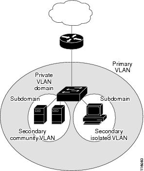
Secondary VLANs
Private VLANs Ports
Private VLANs provide Layer 2 isolation between ports within the same private VLAN. Private VLAN ports are access ports that are one of these types:
-
Promiscuous—A promiscuous port belongs to the primary VLAN and can communicate with all interfaces, including the community and isolated host ports that belong to the secondary VLANs associated with the primary VLAN.
-
Isolated—An isolated port is a host port that belongs to an isolated secondary VLAN. It has complete Layer 2 separation from other ports within the same private VLAN, except for the promiscuous ports. Private VLANs block all traffic to isolated ports except traffic from promiscuous ports. Traffic received from an isolated port is forwarded only to promiscuous ports.
-
Community—A community port is a host port that belongs to a community secondary VLAN. Community ports communicate with other ports in the same community VLAN and with promiscuous ports. These interfaces are isolated at Layer 2 from all other interfaces in other communities and from isolated ports within their private VLAN.
Note | Trunk ports carry traffic from regular VLANs and also from primary, isolated, and community VLANs. |
Primary and secondary VLANs have these characteristics:
-
Primary VLAN—A private VLAN has only one primary VLAN. Every port in a private VLAN is a member of the primary VLAN. The primary VLAN carries unidirectional traffic downstream from the promiscuous ports to the (isolated and community) host ports and to other promiscuous ports.
-
Isolated VLAN —A private VLAN has only one isolated VLAN. An isolated VLAN is a secondary VLAN that carries unidirectional traffic upstream from the hosts toward the promiscuous ports and the gateway.
-
Community VLAN—A community VLAN is a secondary VLAN that carries upstream traffic from the community ports to the promiscuous port gateways and to other host ports in the same community. You can configure multiple community VLANs in a private VLAN.
A promiscuous port can serve only one primary VLAN, one isolated VLAN, and multiple community VLANs. Layer 3 gateways are typically connected to the switch through a promiscuous port. With a promiscuous port, you can connect a wide range of devices as access points to a private VLAN. For example, you can use a promiscuous port to monitor or back up all the private VLAN servers from an administration workstation.
Private VLANs in Networks
In a switched environment, you can assign an individual private VLAN and associated IP subnet to each individual or common group of end stations. The end stations need to communicate only with a default gateway to communicate outside the private VLAN.
You can use private VLANs to control access to end stations in these ways:
Configure selected interfaces connected to end stations as isolated ports to prevent any communication at Layer 2. For example, if the end stations are servers, this configuration prevents Layer 2 communication between the servers.
Configure interfaces connected to default gateways and selected end stations (for example, backup servers) as promiscuous ports to allow all end stations access to a default gateway.
You can extend private VLANs across multiple devices by trunking the primary, isolated, and community VLANs to other devices that support private VLANs. To maintain the security of your private VLAN configuration and to avoid other use of the VLANs configured as private VLANs, configure private VLANs on all intermediate devices, including devices that have no private VLAN ports.
IP Addressing Scheme with Private VLANs
Assigning a separate VLAN to each customer creates an inefficient IP addressing scheme:
Assigning a block of addresses to a customer VLAN can result in unused IP addresses.
If the number of devices in the VLAN increases, the number of assigned address might not be large enough to accommodate them.
These problems are reduced by using private VLANs, where all members in the private VLAN share a common address space, which is allocated to the primary VLAN. Hosts are connected to secondary VLANs, and the DHCP server assigns them IP addresses from the block of addresses allocated to the primary VLAN. Subsequent IP addresses can be assigned to customer devices in different secondary VLANs, but in the same primary VLAN. When new devices are added, the DHCP server assigns them the next available address from a large pool of subnet addresses.
Private VLANs Across Multiple Switches
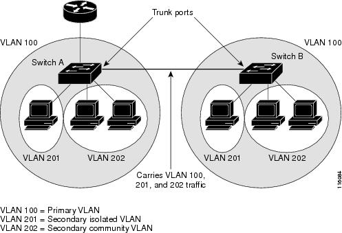
Private VLANs are supported in transparent mode for VTP 1, 2 and 3. Private vlan is also supported on server mode for VTP 3. If we have a server client setup using VTP 3, private vlans configured on the server should be reflected on the client.
Private-VLAN Interaction with Other Features
Private VLANs and Unicast, Broadcast, and Multicast Traffic
In regular VLANs, devices in the same VLAN can communicate with each other at the Layer 2 level, but devices connected to interfaces in different VLANs must communicate at the Layer 3 level. In private VLANs, the promiscuous ports are members of the primary VLAN, while the host ports belong to secondary VLANs. Because the secondary VLAN is associated to the primary VLAN, members of the these VLANs can communicate with each other at the Layer 2 level.
In a regular VLAN, broadcasts are forwarded to all ports in that VLAN. Private VLAN broadcast forwarding depends on the port sending the broadcast:
-
An isolated port sends a broadcast only to the promiscuous ports or trunk ports.
-
A community port sends a broadcast to all promiscuous ports, trunk ports, and ports in the same community VLAN.
-
A promiscuous port sends a broadcast to all ports in the private VLAN (other promiscuous ports, trunk ports, isolated ports, and community ports).
Multicast traffic is routed or bridged across private VLAN boundaries and within a single community VLAN. Multicast traffic is not forwarded between ports in the same isolated VLAN or between ports in different secondary VLANs.
Private VLAN multicast forwarding supports the following:
Private VLANs and SVIs
In a Layer 3 switch, a switch virtual interface (SVI) represents the Layer 3 interface of a VLAN. Layer 3 devices communicate with a private VLAN only through the primary VLAN and not through secondary VLANs. Configure Layer 3 VLAN interfaces (SVIs) only for primary VLANs. You cannot configure Layer 3 VLAN interfaces for secondary VLANs. SVIs for secondary VLANs are inactive while the VLAN is configured as a secondary VLAN.
-
If you try to configure a VLAN with an active SVI as a secondary VLAN, the configuration is not allowed until you disable the SVI.
-
If you try to create an SVI on a VLAN that is configured as a secondary VLAN and the secondary VLAN is already mapped at Layer 3, the SVI is not created, and an error is returned. If the SVI is not mapped at Layer 3, the SVI is created, but it is automatically shut down.
When the primary VLAN is associated with and mapped to the secondary VLAN, any configuration on the primary VLAN is propagated to the secondary VLAN SVIs. For example, if you assign an IP subnet to the primary VLAN SVI, this subnet is the IP subnet address of the entire private VLAN.
Private VLANs and Switch Stacks
Private VLANs can operate within the switch stack, and private-VLAN ports can reside on different stack members. However, the following changes to the stack can impact private-VLAN operation:
-
If a stack contains only one private-VLAN promiscuous port and the stack member that contains that port is removed from the stack, host ports in that private VLAN lose connectivity outside the private VLAN.
-
If a stack master stack that contains the only private-VLAN promiscuous port in the stack fails or leaves the stack and a new stack master is elected, host ports in a private VLAN that had its promiscuous port on the old stack master lose connectivity outside of the private VLAN.
-
If two stacks merge, private VLANs on the winning stack are not affected, but private-VLAN configuration on the losing switch is lost when that switch reboots.
Private VLAN with Dynamic Mac Address
The Mac addresses learnt in the secondary VLAN are replicated to the primary VLAN and not vice-versa. This saves the hardware l2 cam space. The primary VLAN is always used for forwarding lookups in both directions.
Dynamic MAC addresses learned in Primary VLAN of a private VLAN are then, if required, replicated in the secondary VLANs. For example, if a mac-address is dynamically received on the secondary VLAN, it will be learnt as part of primary VLAN. In case of isolated VLANs, a blocked entry for the same mac will be added to secondary VLAN in the mac address table. So, mac learnt on host ports in secondary domain are installed as blocked type entries. All mac entries are learnt on secondary VLANs, even if the traffic ingresses from primary VLAN.
However, if a mac-address is dynamically learnt in the primary VLAN it will not get replicated in the associated secondary VLANS.
Private VLAN with Static Mac Address
Users are not required to replicate the Static Mac Address CLI for private VLAN hosts as compare to legacy model.
Example:
-
In the legacy model, if the user configures a static mac address, they need to add same mac static mac-address in the associated VLAN too. For example, if mac-address A is user configured on port 1/0/1 in VLAN 101, where VLAN 101 is a secondary VLAN and VLAN 100 is a primary VLAN, then the user has to configure
mac-address static A vlan 101 interface G1/0/1
mac-address static A vlan 100 interface G1/0/1
-
In this switch, the user does not need to replicate the mac address to the associated VLAN. For the above example, user has to configure only
mac-address static A vlan 101 interface G1/0/1
Private VLAN Interaction with VACL/QOS
Private VLANs are bidirectional in case of this switch, as compared to “Unidirectional” in other platforms.
After layer-2 forward lookup, proper egress VLAN mapping happens and all the egress VLAN based feature processing happens in the egress VLAN context.
When a frame in Layer-2 is forwarded within a private VLAN, the VLAN map is applied at the ingress side and at the egress side. When a frame is routed from inside a private VLAN to an external port, the private-VLAN map is applied at the ingress side. Similarly, when the frame is routed from an external port to a Private VLAN, the private-VLAN is applied at the egress side. This is applicable to both bridged and routed traffic.
Bridging:
-
For upstream traffic from secondary VLAN to primary VLAN, the MAP of the secondary VLAN is applied on the ingress side and the MAP of the primary VLAN is applied on the egress side.
-
For downstream traffic from primary VLAN to secondary VLAN, the MAP of the primary VLAN is applied in the ingress direction and the MAP of the secondary VLAN is applied in the egress direction.
Routing
If we have two private VLAN domains - PV1 (sec1, prim1) and PV2 (sec2, prim2). For frames routed from PV1 to PV2:
-
The MAP of sec1 and L3 ACL of prim1 is applied in the ingress port.
-
The MAP of sec2 and L3 ACL of prim2 is applied in the egress port.
For packets going upstream or downstream from isolated host port to promiscuous port, the isolated VLAN’s VACL is applied in the ingress direction and primary VLAN’s VACL is applied in the egress direction. This allows user to configure different VACL for different secondary VLAN in a same primary VLAN domain.
Note | 2-way community VLAN is now not required as the private VLANS on this switch are always bi-directional. |
Private VLANs and HA Support
PVLAN will work seamlessly with High Availability (HA) feature. The Private VLAN existing on the master before switchover should be the same after switchover (new master should have similar PVLAN configuration both on IOS side and FED side as that of the old master).
Private-VLAN Configuration Guidelines
Default Private-VLAN Configurations
No private VLANs are configured.
Secondary and Primary VLAN Configuration
Follow these guidelines when configuring private VLANs:
-
Private VLANs are supported in transparent mode for VTP 1, 2 and 3. If the switch is running VTP version 1 or 2, you must set VTP to transparent mode. After you configure a private VLAN, you should not change the VTP mode to client or server. VTP version 3 supports private VLANs in all modes.
-
With VTP version 1 or 2, after you have configured private VLANs, use the copy running-config startup config privileged EXEC command to save the VTP transparent mode configuration and private-VLAN configuration in the switch startup configuration file. Otherwise, if the switch resets, it defaults to VTP server mode, which does not support private VLANs. VTP version 3 does support private VLANs.
-
VTP version 1 and 2 do not propagate private-VLAN configuration. You must configure private VLANs on each device where you want private-VLAN ports unless the devices are running VTP version 3, as VTP3 propagate private vlans.
-
You cannot configure VLAN 1 or VLANs 1002 to 1005 as primary or secondary VLANs. Extended VLANs (VLAN IDs 1006 to 4094) can belong to private VLANs.
-
A primary VLAN can have one isolated VLAN and multiple community VLANs associated with it. An isolated or community VLAN can have only one primary VLAN associated with it.
-
Although a private VLAN contains more than one VLAN, only one Spanning Tree Protocol (STP) instance runs for the entire private VLAN. When a secondary VLAN is associated with the primary VLAN, the STP parameters of the primary VLAN are propagated to the secondary VLAN.
-
When copying a PVLAN configuration from a tftp server and applying it on a running-config, the PVLAN association will not be formed. You will need to check and ensure that the primary VLAN is associated to all the secondary VLANs.
You can also use configure replace flash:config_file force instead of copy flash:config_file running-config.
-
You can enable DHCP snooping on private VLANs. When you enable DHCP snooping on the primary VLAN, it is propagated to the secondary VLANs. If you configure DHCP on a secondary VLAN, the configuration does not take effect if the primary VLAN is already configured.
-
When you enable IP source guard on private-VLAN ports, you must enable DHCP snooping on the primary VLAN.
-
We recommend that you prune the private VLANs from the trunks on devices that carry no traffic in the private VLANs.
-
You can apply different quality of service (QoS) configurations to primary, isolated, and community VLANs.
-
Note the following considerations for sticky ARP:
-
Sticky ARP entries are those learned on SVIs and Layer 3 interfaces. These entries do not age out.
-
The ip sticky-arp global configuration command is supported only on SVIs belonging to private VLANs.
-
The ip sticky-arp interface configuration command is only supported on:
For more information about using the ip sticky-arp global configuration and the ip sticky-arp interface configuration commands, see the command reference for this release.
-
-
You can configure VLAN maps on primary and secondary VLANs. However, we recommend that you configure the same VLAN maps on private-VLAN primary and secondary VLANs.
-
PVLANs are bidirectional. They can be applied at both the ingress and egress sides.
When a frame inLayer-2 is forwarded within a private VLAN, the VLAN map is applied at the ingress side and at the egress side. When a frame is routed from inside a private VLAN to an external port, the private-VLAN map is applied at the ingress side. Similarly, when the frame is routed from an external port to a Private VLAN, the private-VLAN is applied at the egress side.
Bridging
-
For upstream traffic from secondary VLAN to primary VLAN, the MAP of the secondary VLAN is applied on the ingress side and the MAP of the primary VLAN is applied on the egress side.
-
For downstream traffic from primary VLAN to secondary VLAN, the MAP of the primary VLAN is applied in the ingress direction and the MAP of the secondary VLAN is applied in the egress direction.
Routing
If we have two private VLAN domains - PV1 (sec1, prim1) and PV2 (sec2, prim2). For frames routed from PV1 to PV2:
-
The MAP of sec1 and L3 ACL of prim1 is applied in the ingress port .
-
The MAP of sec1 and L3 ACL of prim2 is applied in the egress port.
-
For packets going upstream or downstream from isolated host port to promiscuous port, the isolated VLAN’s VACL is applied in the ingress direction and primary VLAN’S VACL is applied in the egress direction. This allows user to configure different VACL for different secondary VLAN in a same primary VLAN domain.
To filter out specific IP traffic for a private VLAN, you should apply the VLAN map to both the primary and secondary VLANs.
-
-
You can apply router ACLs only on the primary-VLAN SVIs. The ACL is applied to both primary and secondary VLAN Layer 3 traffic.
-
Although private VLANs provide host isolation at Layer 2, hosts can communicate with each other at Layer 3.
-
Private VLANs support these Switched Port Analyzer (SPAN) features:
Private VLAN Port Configuration
Follow these guidelines when configuring private VLAN ports:
Use only the private VLAN configuration commands to assign ports to primary, isolated, or community VLANs. Layer 2 access ports assigned to the VLANs that you configure as primary, isolated, or community VLANs are inactive while the VLAN is part of the private VLAN configuration. Layer 2 trunk interfaces remain in the STP forwarding state.
Do not configure ports that belong to a PAgP or LACP EtherChannel as private VLAN ports. While a port is part of the private VLAN configuration, any EtherChannel configuration for it is inactive.
Enable Port Fast and BPDU guard on isolated and community host ports to prevent STP loops due to misconfigurations and to speed up STP convergence. When enabled, STP applies the BPDU guard feature to all Port Fast-configured Layer 2 LAN ports. Do not enable Port Fast and BPDU guard on promiscuous ports.
If you delete a VLAN used in the private VLAN configuration, the private VLAN ports associated with the VLAN become inactive.
Private VLAN ports can be on different network devices if the devices are trunk-connected and the primary and secondary VLANs have not been removed from the trunk.
How to Configure Private VLANs
Configuring Private VLANs
To configure a private VLAN, perform these steps:
Note | Private vlans are supported in transparent mode for VTP 1, 2 and 3. Private VLANS are also supported on server mode with VTP 3. |
1. Set VTP mode to transparent.
2. Create the primary and secondary VLANs and associate them.
3. Configure interfaces to be isolated or community host ports, and assign VLAN membership to the host port.
4. Configure interfaces as promiscuous ports, and map the promiscuous ports to the primary-secondary VLAN pair.
5. If inter-VLAN routing will be used, configure the primary SVI, and map secondary VLANs to the primary.
6. Verify private-VLAN configuration.
DETAILED STEPS
| Step 1 | Set VTP mode to
transparent.
| ||
| Step 2 | Create the
primary and secondary VLANs and associate them.
| ||
| Step 3 | Configure
interfaces to be isolated or community host ports, and assign VLAN membership
to the host port.
See the Configuring a Layer 2 Interface as a Private VLAN Host Port | ||
| Step 4 | Configure
interfaces as promiscuous ports, and map the promiscuous ports to the
primary-secondary VLAN pair.
See the Configuring a Layer 2 Interface as a Private VLAN Promiscuous Port | ||
| Step 5 | If inter-VLAN
routing will be used, configure the primary SVI, and map secondary VLANs to the
primary.
See the Mapping Secondary VLANs to a Primary VLAN Layer 3 VLAN Interface | ||
| Step 6 | Verify private-VLAN configuration. |
Configuring and Associating VLANs in a Private VLAN
The private-vlan commands do not take effect until you exit VLAN configuration mode.
To configure and associate VLANs in a Private VLAN, perform these steps:
1.
enable
14.
private-vlan
community
15.
exit
16.
vlan
vlan-id
17.
private-vlan
association [add |
remove]
secondary_vlan_list
DETAILED STEPS
Configuring a Layer 2 Interface as a Private VLAN Host Port
Follow these steps to configure a Layer 2 interface as a private-VLAN host port and to associate it with primary and secondary VLANs:
Note | Isolated and community VLANs are both secondary VLANs. |
1.
enable
4.
switchport mode
private-vlan host
5.
switchport
private-vlan host-association
primary_vlan_id
secondary_vlan_id
7.
show interfaces [interface-id]
switchport
8.
copy running-config
startup-config
DETAILED STEPS
| Command or Action | Purpose | |||
|---|---|---|---|---|
| Step 1 |
enable
Example:
Switch> enable
|
Enables privileged EXEC mode. Enter your password if prompted. | ||
| Step 2 | configure
terminal
Example: Switch# configure terminal | |||
| Step 3 | interface
interface-id
Example: Switch(config)# interface gigabitethernet1/0/22 |
Enters interface configuration mode for the Layer 2 interface to be configured. | ||
| Step 4 | switchport mode
private-vlan host
Example: Switch(config-if)# switchport mode private-vlan host | |||
| Step 5 | switchport
private-vlan host-association
primary_vlan_id
secondary_vlan_id
Example: Switch(config-if)# switchport private-vlan host-association 20 501 |
Associates the Layer 2 port with a private VLAN.
| ||
| Step 6 | end
Example: Switch(config)# end | |||
| Step 7 | show interfaces [interface-id]
switchport
Example: Switch# show interfaces gigabitethernet1/0/22 switchport | |||
| Step 8 | copy running-config
startup-config
Example:
Switch# copy running-config startup-config
|
(Optional) Saves your entries in the configuration file. |
Configuring a Layer 2 Interface as a Private VLAN Promiscuous Port
Follow these steps to configure a Layer 2 interface as a private VLAN promiscuous port and map it to primary and secondary VLANs:
Note | Isolated and community VLANs are both secondary VLANs. |
1.
enable
4.
switchport mode
private-vlan promiscuous
5.
switchport private-vlan
mapping
primary_vlan_id {add |
remove}
secondary_vlan_list
DETAILED STEPS
| Command or Action | Purpose | |
|---|---|---|
| Step 1 |
enable
Example:
Switch> enable
|
Enables privileged EXEC mode. Enter your password if prompted. |
| Step 2 | configure
terminal
Example: Switch# configure terminal | |
| Step 3 | interface
interface-id
Example: Switch(config)# interface gigabitethernet1/0/2 |
Enters interface configuration mode for the Layer 2 interface to be configured. |
| Step 4 | switchport mode
private-vlan promiscuous
Example: Switch(config-if)# switchport mode private-vlan promiscuous |
Configures the Layer 2 port as a private VLAN promiscuous port. |
| Step 5 | switchport private-vlan
mapping
primary_vlan_id {add |
remove}
secondary_vlan_list
Example: Switch(config-if)# switchport private-vlan mapping 20 add 501-503 |
Maps the private VLAN promiscuous port to a primary VLAN and to selected secondary VLANs.
|
| Step 6 | end
Example: Switch(config)# end | |
| Step 7 | show interfaces [interface-id]
switchport
Example: Switch# show interfaces gigabitethernet1/0/2 switchport | |
| Step 8 | copy running-config startup
config
Example: Switch# copy running-config startup-config |
Saves your entries in the switch startup configuration file. |
Mapping Secondary VLANs to a Primary VLAN Layer 3 VLAN Interface
If the private VLAN will be used for inter-VLAN routing, you configure an SVI for the primary VLAN and map secondary VLANs to the SVI.
Note | Isolated and community VLANs are both secondary VLANs. |
Follow these steps to map secondary VLANs to the SVI of a primary VLAN to allow Layer 3 switching of private VLAN traffic:
1.
enable
3.
interface vlan
primary_vlan_id
4.
private-vlan mapping
[add |
remove]
secondary_vlan_list
DETAILED STEPS
| Command or Action | Purpose | |||
|---|---|---|---|---|
| Step 1 |
enable
Example:
Switch> enable
|
Enables privileged EXEC mode. Enter your password if prompted. | ||
| Step 2 | configure
terminal
Example: Switch# configure terminal | |||
| Step 3 | interface vlan
primary_vlan_id
Example: Switch(config)# interface vlan 20 |
Enters interface configuration mode for the primary VLAN, and configures the VLAN as an SVI. The VLAN ID range is 2 to 1001 and 1006 to 4094. | ||
| Step 4 | private-vlan mapping
[add |
remove]
secondary_vlan_list
Example: Switch(config-if)# private-vlan mapping 501-503 |
Maps the secondary VLANs to the Layer 3 VLAN interface of a primary VLAN to allow Layer 3 switching of private VLAN ingress traffic.
| ||
| Step 5 | end
Example: Switch(config)# end | |||
| Step 6 | show interface
private-vlan mapping
Example: Switch# show interfaces private-vlan mapping | |||
| Step 7 | copy running-config startup
config
Example: Switch# copy running-config startup-config |
Saves your entries in the switch startup configuration file. |
Monitoring Private VLANs
|
Command |
Purpose |
|---|---|
|
Displays the status of interfaces, including the VLANs to which they belongs. |
|
|
Displays the private VLAN information for the Switch or Switch stack. |
|
|
Displays information about the private VLAN mapping for VLAN SVIs. |
|
|
show platform vlan pvlan |
Displays PVLAN information on FED side |
|
show platform vlan pvlan hardware |
Displays all the hardware resources held by PVLANs on FED side |
Configuration Examples for Private VLANs
Example: Configuring and Associating VLANs in a Private VLAN
This example shows how to configure VLAN 20 as a primary VLAN, VLAN 501 as an isolated VLAN, and VLANs 502 and 503 as community VLANs, to associate them in a private VLAN, and to verify the configuration:
Switch# configure terminal
Switch(config)# vlan 20
Switch(config-vlan)# private-vlan primary
Switch(config-vlan)# exit
Switch(config)# vlan 501
Switch(config-vlan)# private-vlan isolated
Switch(config-vlan)# exit
Switch(config)# vlan 502
Switch(config-vlan)# private-vlan community
Switch(config-vlan)# exit
Switch(config)# vlan 503
Switch(config-vlan)# private-vlan community
Switch(config-vlan)# exit
Switch(config)# vlan 20
Switch(config-vlan)# private-vlan association 501-503
Switch(config-vlan)# end
Switch# show vlan private-vlan
Primary   Secondary 					Type
--------- -------------- -----------------
20        501            isolated
20        502            community
20        503            community
Example: Configuring an Interface as a Host Port
This example shows how to configure an interface as a private VLAN host port, associate it with a private VLAN pair, and verify the configuration:
Switch# configure terminal
Switch(config)# interface gigabitethernet1/0/22
Switch(config-if)# switchport mode private-vlan host
Switch(config-if)# switchport private-vlan host-association 20 501
Switch(config-if)# end
Switch# show interfaces gigabitethernet1/0/22 switchport
Name: Gi1/0/22
Switchport: Enabled
Administrative Mode: private-vlan host
Operational Mode: private-vlan host
Administrative Trunking Encapsulation: negotiate
Operational Trunking Encapsulation: native
Negotiation of Trunking: Off
Access Mode VLAN: 1 (default)
Trunking Native Mode VLAN: 1 (default)
Administrative Native VLAN tagging: enabled
Voice VLAN: none
Administrative private-vlan host-association: 20 501
Administrative private-vlan mapping: none
Administrative private-vlan trunk native VLAN: none
Administrative private-vlan trunk Native VLAN tagging: enabled
Administrative private-vlan trunk encapsulation: dot1q
Administrative private-vlan trunk normal VLANs: none
Administrative private-vlan trunk private VLANs: none
Operational private-vlan:
20 501

<output truncated>
Example: Configuring an Interface as a Private VLAN Promiscuous Port
This example shows how to configure an interface as a private VLAN promiscuous port and map it to a private VLAN. The interface is a member of primary VLAN 20 and secondary VLANs 501 to 503 are mapped to it.
Switch# configure terminal
Switch(config)# interface gigabitethernet1/0/2
Switch(config-if)# switchport mode private-vlan promiscous
Switch(config-if)# switchport private-vlan mapping 20 add 501-503
Switch(config-if)# end
Use the show vlan private-vlan or the show interface status privileged EXEC command to display primary and secondary VLANs and private-VLAN ports on the Switch.
Example: Mapping Secondary VLANs to a Primary VLAN Interface
This example shows how to map the interfaces fo VLANs 501 and 502 to primary VLAN 10, which permits routing of secondary VLAN ingress traffic from private VLANs 501 and 502:
Switch# configure terminal
Switch(config)# interface vlan 20
Switch(config-if)# private-vlan mapping 501-503
Switch(config-if)# end
Switch# show interfaces private-vlan mapping
Interface Secondary VLAN Type
--------- -------------- -----------------
vlan20    501            isolated
vlan20    502            community
vlan20    503            community
Example: Monitoring Private VLANs
This example shows output from the show vlan private-vlan command:
Switch# show vlan private-vlan
Primary Secondary Type              Ports
------- --------- ----------------- ------------------------------------------
20      501       isolated          Gi1/0/22, Gi1/0/2
20      502       community         Gi1/0/2
20      503       community									Gi1/0/2
Where to Go Next
You can configure the following:
Additional References
Related Documents
| Related Topic | Document Title |
|---|---|
| CLI commands | LAN
Switching Command Reference, Cisco IOS Release
|
Standards and RFCs
| Standard/RFC | Title |
|---|---|
|
RFC 1573 |
|
|
RFC 1757 |
|
|
RFC 2021 |
MIBs
| MIB | MIBs Link |
|---|---|
All supported MIBs for this release.
|
To locate and download MIBs for selected platforms, Cisco IOS releases, and feature sets, use Cisco MIB Locator found at the following URL: |
Technical Assistance
| Description | Link |
|---|---|
|
The Cisco Support website provides extensive online resources, including documentation and tools for troubleshooting and resolving technical issues with Cisco products and technologies. To receive security and technical information about your products, you can subscribe to various services, such as the Product Alert Tool (accessed from Field Notices), the Cisco Technical Services Newsletter, and Really Simple Syndication (RSS) Feeds. Access to most tools on the Cisco Support website requires a Cisco.com user ID and password. |
 Feedback