Multicast Virtual Private Network

Feature history for multicast VPN

Use this table to identify when specific MVPN capabilities were introduced and their compatibility with various Cisco Catalyst switches and supervisor modules.

Table 1. Feature history for multicast VPN

Release

Feature

Feature information

Cisco IOS XE 26.2.1

Multicast VPN: MVPN Profile 0, also called Draft-Rosen MVPN, enables service providers to configure and support multicast traffic in an MPLS VPN environment. It uses PIM for multicast signaling and GRE tunnels between provider edge routers.

Cisco C9610 Series Smart Switches

Cisco C9550 Series Smart Switches

Cisco C9350 Series Smart Switches

Use the Cisco Feature Navigator to find information about platform and software image support. To access Cisco Feature Navigator, go to https://cfnng.cisco.com/.
Configuring multicast virtual private network

Multicast VPN (MVPN) is a multicast routing and forwarding solution that:

  • supports routing and forwarding of multicast packets for each individual VRF instance,

  • provides a mechanism to transport VPN multicast packets across the service provider backbone, and

  • allows an enterprise to transparently interconnect its private network across a service provider network backbone.

Operation of multicast VPN

An MVPN allows an enterprise to transparently interconnect its private network across the network backbone of a service provider. The use of an MVPN to interconnect an enterprise network in this way does not change the way that enterprise network is administered, nor does it change general enterprise connectivity.

A VPN is network connectivity across a shared infrastructure, such as an ISP. Its function is to provide the same policies and performance as a private network, at a reduced cost of ownership, thus creating many opportunities for cost savings through operations and infrastructure.

Prerequisites for configuring multicast VPN

Ensure that you have completed these configuration requirements:

  • Enable IP multicast on the device.

  • Configure PIM interfaces according to the requirements of your multicast network.

Refer to the “Configuring Basic IP Multicast” module for detailed instructions on enabling IP multicast and configuring PIM interfaces.

Restrictions for configuring multicast VPN

BGP peering restrictions

Ensure that Border Gateway Protocol (BGP) peering is configured correctly to support the default multicast distribution tree (MDT):

  • The update source interface for BGP peerings must be the same for all BGP peerings configured on the device.

  • If you use a loopback address for BGP peering, PIM sparse mode must be enabled on the loopback address.

  • Multiple BGP peering update sources are not supported. Configuring multiple sources can break MVPN reverse path forwarding (RPF) checking.

Feature support restrictions

Note these limitations for MVPN feature support:

  • Multicast VPN over Extranet is not supported.

The source IP address of the MVPN tunnels is determined by the highest IP address used for the BGP peering update source. If this IP address does not match the IP address used as the BGP peering address with the remote provider edge (PE) device, MVPN will not function properly.

Information About Configuring Multicast VPN

Benefits of multicast VPN

Multicast VPN (MVPN) is a networking solution that:

  • provides a scalable method to dynamically send information to multiple locations,

  • provides high-speed information delivery, and

  • provides connectivity through a shared infrastructure.

Multicast routing and forwarding

Multicast routing and forwarding is a mechanism in MVPN that:

  • introduces multicast routing information to the VPN routing and forwarding table,

  • performs forwarding according to information in the Multicast VPN routing and forwarding instance (MVRF), and

  • operates without using label switching.

Multicast domains

A set of MVRFs that can send multicast traffic to each other constitutes a multicast domain. For example, the multicast domain for a customer that wanted to send certain types of multicast traffic to all global employees would consist of all CE routers associated with that enterprise.

Multicast distribution trees

A multicast distribution tree (MDT) is a path in an MVPN that:

  • defines how PE routers send multicast data and control messages to other PE routers in a multicast domain,

  • supports static default MDTs for every multicast domain, and

  • enables dynamic creation of data MDTs for high-bandwidth transmission.

Default MDT: A static multicast distribution tree created for each multicast domain to transport multicast data and control messages to all PE routers in the domain.

Data MDT: A dynamic multicast distribution tree created for high-bandwidth transmission (S, G) entries to ensure optimal traffic forwarding in the MPLS VPN core.

Data MDT switchover mechanism

The threshold at which the data MDT is created can be configured on a per-router or a per-VRF basis. When the multicast transmission exceeds the defined threshold, the sending PE router creates the data MDT and sends a UDP message to all routers on the default MDT. Statistics are examined once every second. Switchover occurs between 3 and 13 seconds after the UDP message is sent.

Data MDTs are created only for (S, G) multicast route entries within the VRF multicast routing table. They are not created for (*, G) entries regardless of the source data rate.

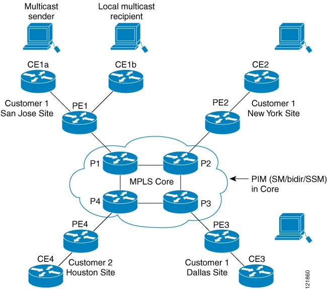
Figure 1. Default multicast distribution tree overview

Service provider network interconnects CE routers across San Jose, New York, and Dallas, with P routers P1, P2, and P3.
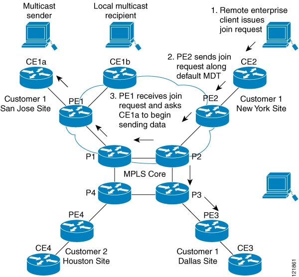
Figure 2. Initializing the data MDT
A source site in San Jose sends high-bandwidth multicast data, triggering the sending PE router to create a data MDT.

Multicast tunnel interface

A multicast tunnel interface (MTI) is an interface that:

  • connects a Multicast VPN routing and forwarding (MVRF) instance to the global MVRF,

  • serves as a conduit from which all MVRF traffic is sourced, and

  • provides the MVRF with access to the multicast domain.

MTI creation

One tunnel interface is created per MVRF instance. All MVRF traffic is sourced from this tunnel interface to access the shared multicast infrastructure.

MDT address family in BGP for multicast VPN support

The MDT address family in BGP is a subaddress family that:

  • uses the mdt keyword within the address-family ipv4 command,

  • passes the source PE address and MDT group address to PIM using BGP MDT Subaddress Family Identifier (SAFI) updates, and

  • enables PE routers to discover each other and establish distribution trees in an MVPN environment.

BGP advertisement methods for multicast VPN support

BGP advertisement methods in MVPN are mechanisms that:

  • communicate source PE and default MDT group information between PE routers,

  • enable receiver PE routers to build (S, G) joins toward the source PE in PIM-SSM environments, and

  • eliminate the need for a rendezvous point (RP) when building distribution trees.

PIM-SM vs PIM-SSM advertisement

In a single autonomous system using PIM sparse mode (PIM-SM) with an RP, PE routers discover each other through the RP over the Multicast Tunnel Interface (MTI). The source PE sends register messages to the RP, and remote PE routers send (*, G) joins toward the RP.

In a PIM Source Specific Multicast (PIM-SSM) environment, the receiver PE needs source PE and default MDT group information to build (S, G) joins directly toward the source PE. This information is sent using BGP.

BGP extended community

The BGP extended community in MVPN is a BGP attribute that:

  • carries the MDT group address for an MVRF instance,

  • works in combination with VPNv4 prefixes using Route Distinguisher (RD) Type 2 to advertise source PE addresses, and

  • enables PE routers to establish SSM trees to each other when standardized MDT SAFI support is not used.

Limitations of BGP extended community for MVPN


Note


Prior to the introduction of MDT SAFI support, the BGP extended community attribute was used as an interim solution. This attribute has certain limitations: it cannot be used in inter-AS scenarios because it is nontransitive, and it uses RD Type 2, which is not a supported standard.


How to Configure Multicast VPN

Configuring a default MDT group for a VRF

Configure a default MDT group to enable a provider edge (PE) device to transport multicast data and control messages across the service provider backbone to all other PE devices in the same multicast domain.

The default MDT group must be the same group configured on all devices that belong to the same VPN. The source IP address will be the address used to source the BGP sessions.

Procedure


Step 1

enable

Example:

Device> enable

Enables privileged EXEC mode. Enter your password if prompted.

Step 2

configure terminal

Example:

Device# configure terminal

Enters global configuration mode.

Step 3

ip multicast-routing

Example:

Device(config)# ip multicast-routing

Enables multicast routing.

Step 4

ip multicast-routing vrf vrf-name

Example:

Device(config)# ip multicast-routing vrf vrf1

Enables the MVPN VRF instance for multicast routing.

Step 5

vrf definition vrf-name

Example:

Device(config)# vrf definition vrf1

Enters VRF configuration mode and defines the VPN routing instance by assigning a VRF name.

Step 6

rd route-distinguisher

Example:

Device(config-vrf)# rd 1:1

Creates routing and forwarding tables for a VRF. The route-distinguisher argument specifies to add an 8-byte value to an IPv4 prefix to create a VPN IPv4 prefix. You can enter a route-distinguisher in either of these formats:

  • 16-bit autonomous system number (ASN): your 32-bit number. For example, 101:3.

  • 32-bit IP address: your 16-bit number. For example, 192.168.122.15:1.

Step 7

route-target both ASN:nn or IP-address:nn

Example:

Device(config-vrf)# route-target both 1:1

Creates a route-target extended community for a VRF. The both keyword specifies to import both import and export routing information to the target VPN extended community.

Step 8

address family ipv4 unicast

Example:

Device(config-vrf)# address family ipv4 unicast

Enters VRF address family configuration mode. The ipv4 keyword specifies an IPv4 address family for a VRF.

Step 9

mdt default group-address

Example:

Device(config-vrf-af)# mdt default 226.10.10.10

Configures the multicast group address range for data MDT groups for a VRF. A tunnel interface is created as a result of this command. The default MDT group address configuration must be the same on all PEs in the same VRF.

Step 10

end

Example:

Device(config-vrf-af)# end

Returns to privileged EXEC mode.

Step 11

configure terminal

Example:

Device# configure terminal

Enters global configuration mode.

Step 12

ip pim vrf vrf-name rp-address value

Example:

Device(config-vrf-af)# ip pim vrf vrf1 rp-address 1.1.1.1

Enters the rendezvous point (RP) configuration mode for PIM sparse mode in a VRF.


Configuring the data multicast group

Configure the data multicast group to provide a pool of dynamically assigned IP addresses for high-bandwidth multicast streams. This ensures optimal traffic forwarding by using dedicated distribution trees for high-rate sources.

Multicast groups used to create the data MDT group are dynamically chosen from a pool of configured IP addresses.

Procedure


Step 1

enable

Example:

Device> enable

Enables privileged EXEC mode. Enter your password if prompted.

Step 2

configure terminal

Example:

Device# configure terminal

Enters global configuration mode.

Step 3

vrf definition vrf-name

Example:

Device(config)# vrf definition vrf1

Enters VRF configuration mode and defines the VPN routing instance by assigning a VRF name.

Step 4

rd route-distinguisher

Example:

Device(config-vrf)# rd 1:1

Creates routing and forwarding tables for a VRF. The route-distinguisher argument specifies to add an 8-byte value to an IPv4 prefix to create a VPN IPv4 prefix. You can enter a route-distinguisher in either of these formats:

  • 16-bit autonomous system number (ASN): your 32-bit number. For example, 101:3.

  • 32-bit IP address: your 16-bit number. For example, 192.168.122.15:1.

Step 5

route-target both ASN:nn or IP-address:nn

Example:

Device(config-vrf)# route-target both 1:1

Creates a route-target extended community for a VRF. The both keyword specifies to import both import and export routing information to the target VPN extended community.

Step 6

address family ipv4 unicast

Example:

Device(config-vrf)# address family ipv4 unicast

Enters VRF address family configuration mode. The ipv4 keyword specifies an IPv4 address family for a VRF.

Step 7

mdt default group-address

Example:

Device(config-vrf-af)# mdt default 226.10.10.10

Configures the multicast group address range for data MDT groups for a VRF. A tunnel interface is created as a result of this command. The default MDT group address configuration must be the same on all PEs in the same VRF.

Step 8

mdt data group number

Example:

Device(config-vrf-af)# mdt data 232.0.1.0 0.0.0.31

Specifies a range of addresses to be used in the data MDT pool.

Step 9

mdt data threshold kbps

Example:

Device(config-vrf-af)# mdt data threshold 50

Specifies the threshold in kbps for switching from the default MDT to a data MDT. The range is from 1 to 4294967.

Step 10

mdt log-reuse

Example:

Device(config-vrf-af)# mdt log-reuse

(Optional) Enables the recording of data MDT reuse and generates a syslog message when a data MDT has been reused.

Step 11

end

Example:

Device(config-vrf-af)# end

Returns to privileged EXEC mode.


Configuring the MDT address family in BGP for multicast VPN

Configure an MDT address family session on PE devices to establish MDT peering sessions. This allows the discovery of PE routers and the establishment of multicast distribution trees in an MVPN environment.

Before you begin

Ensure that MPLS and Cisco Express Forwarding (CEF) are configured in the BGP network. You must also configure multiprotocol BGP on PE devices that provide VPN services to CE devices.


Note


These policy configuration parameters are not supported:

  • Route-originator attribute

  • Network Layer Reachability Information (NLRI) prefix filtering (prefix lists, distribute lists)

  • Extended community attributes (route target and site of origin)


Perform this task to configure an MDT address family session on PE devices to establish MDT peering sessions for MVPN.

Procedure


Step 1

enable

Example:

Device> enable

Enables privileged EXEC mode. Enter your password if prompted.

Step 2

configure terminal

Example:

Device# configure terminal

Enters global configuration mode.

Step 3

router bgp as-number

Example:

Device(config)# router bgp 65535

Enters router configuration mode and creates a BGP routing process.

Step 4

address-family ipv4 mdt

Example:

Device(config-router)# address-family ipv4 mdt

Enters address family configuration mode to create an IP MDT address family session.

Step 5

neighbor neighbor-address activate

Example:

Device(config-router-af)# neighbor 192.168.1.1 activate

Enables the MDT address family for the specified neighbor.

Step 6

neighbor neighbor-address send-community [both | extended | standard]

Example:

Device(config-router-af)# neighbor 192.168.1.1 send-community extended

Enables community and extended community exchange with the specified neighbor.

Step 7

exit

Example:

Device(config-router-af)# exit

Exits address family configuration mode and returns to router configuration mode.

Step 8

address-family vpnv4

Example:

Device(config-router)# address-family vpnv4

Enters address family configuration mode to create a VPNv4 address family session.

Step 9

neighbor neighbor-address activate

Example:

Device(config-router-af)# neighbor 192.168.1.1 activate

Enables the VPNv4 address family for the specified neighbor.

Step 10

neighbor neighbor-address send-community [both | extended | standard]

Example:

Device(config-router-af)# neighbor 192.168.1.1 send-community extended

Enables community and extended community exchange with the specified neighbor.

Step 11

end

Example:

Device(config-router-af)# end

Exits address family configuration mode and enters privileged EXEC mode.


Verifying information for the MDT default group

Verify the MDT configuration to confirm that Border Gateway Protocol (BGP) advertisements and multicast distribution tree path establishment are functioning as expected.

Procedure


Step 1

enable

Example:

Device> enable

Enables privileged EXEC mode. Enter your password if prompted.

Step 2

show ip pim [vrf vrf-name] mdt bgp

Example:

Device# show ip pim mdt bgp

MDT-default group 232.2.1.4 
rid:1.1.1.1 next_hop:1.1.1.1 

Displays information about the BGP advertisement of the Route Distinguisher (RD) for the MDT default group.

Step 3

show ip pim [vrf vrf-name] mdt send

Example:

Device# show ip pim mdt send

MDT-data send list for VRF:vpn8 
  (source, group)                     MDT-data group      ref_count 
  (10.100.8.10, 225.1.8.1)            232.2.8.0           1 
  (10.100.8.10, 225.1.8.2)            232.2.8.1           1 
  (10.100.8.10, 225.1.8.3)            232.2.8.2           1 
  (10.100.8.10, 225.1.8.4)            232.2.8.3           1 
  (10.100.8.10, 225.1.8.5)            232.2.8.4           1 
  (10.100.8.10, 225.1.8.6)            232.2.8.5           1 
  (10.100.8.10, 225.1.8.7)            232.2.8.6           1 
  (10.100.8.10, 225.1.8.8)            232.2.8.7           1 
  (10.100.8.10, 225.1.8.9)            232.2.8.8           1 
  (10.100.8.10, 225.1.8.10)           232.2.8.9           1 

Displays detailed information about the MDT data group, including MDT advertisements that the specified device has made.

Step 4

show ip pim vrf vrf-name mdt history interval minutes

Example:

Device# show ip pim vrf vrf1 mdt history interval 20

   MDT-data send history for VRF - vrf1 for the past 20 minutes 
MDT-data group        Number of reuse 
     10.9.9.8           3 
     10.9.9.9           2 

Displays the data MDTs that have been reused during the configured interval.


Configuration Examples for Multicast VPN

Example: Configuring MVPN and SSM

Use this example to understand how to configure default and data multicast distribution tree (MDT) groups within the SSM range and accept Auto-RP announcements within the VPN.

In this example, PIM-SSM is configured in the backbone. The default and data MDT groups are configured within the SSM range of IP addresses. Inside the VPN, PIM-SM is configured and only Auto-RP announcements are accepted.


ip vrf vrf1 
 rd 1:1 
 route-target export 1:1 
 route-target import 1:1 
 mdt default 232.0.0.1 
 mdt data 232.0.1.0 0.0.0.255 threshold 500 list 101 
! 
ip pim ssm default 
ip pim vrf vrf1 accept-rp auto-rp 

Example: Enabling a VPN for multicast routing

Use this example to understand the command required to enable multicast routing for a named VRF instance.

In this example, multicast routing is enabled with a VPN routing instance named vrf1:

ip multicast-routing vrf <vrf name>

Example: Configuring the multicast group address range for data MDT groups

Use this example to understand how to define the default MDT group and the data MDT range with wildcard bits for a specific VRF.

In this example, the VPN routing instance is assigned a VRF named blue. The MDT default group for a VPN VRF is 239.1.1.1, and the multicast group address range for MDT groups is 239.1.2.0 with wildcard bits of 0.0.0.3:


ip vrf blue 
 rd 55:1111 
 route-target both 55:1111 
 mdt default 239.1.1.1 
 mdt data 239.1.2.0 0.0.0.3 
 end 

Example: Limiting the number of multicast routes

Use this example to understand how to configure global and VRF-specific multicast route limits and warning thresholds.

In this example, the number of multicast routes that can be added to a multicast routing table is set to 200,000 and the threshold value of the number of mroutes that will cause a warning message to occur is set to 20,000:


!
ip multicast-routing
ip multicast-routing vrf cisco 
ip multicast cache-headers 
ip multicast route-limit 200000 20000 
ip multicast vrf cisco route-limit 200000 20000 
no mpls traffic-eng auto-bw timers frequency 0 
! 

Additional references for configuring multicast VPN

Use these references to find detailed command syntax, usage information, and related technical documentation for Cisco Catalyst switches.

Table 2. Related documents

Related topic

Document title

For complete syntax and usage information for the commands used in this chapter.