IGMP

Feature history for IGMP

This table provides release and platform support information for the features explained in this module.

These features are available in all the releases subsequent to the one they were introduced in, unless noted otherwise.

Release

Feature name and description

Supported platform

Cisco IOS XE 17.18.1

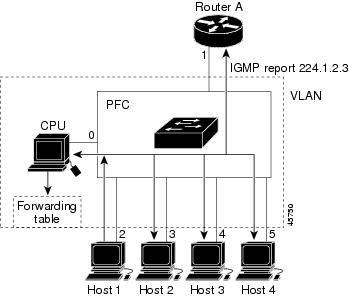
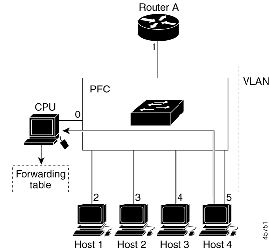
IGMP: IGMP is a communication protocol used between hosts on a LAN and network devices to monitor IP multicast group memberships.

Cisco C9350 Series Smart Switches

Cisco C9610 Series Smart Switches

Understand IGMP

This section describes about Internet Group Management Protocol (IGMP) and its features.

IGMP

IGMP is a communication protocol used between hosts on a LAN and network devices to monitor IP multicast group memberships. To participate in IP multicasting, multicast hosts, routers, and multilayer devices must have IGMP operating.

Role of IGMP

IGMP is used to dynamically register individual hosts in a multicast group on a particular LAN, automatically controlling and limiting multicast traffic using special multicast queriers and hosts. Enabling PIM on an interface also enables IGMP.

  • A querier is a network device, such as a router, that sends query messages to identify the network devices belonging to a specific multicast group.

  • A host is a receiver, including routers, that sends report messages (in response to query messages) to inform the querier of a host membership. Hosts use IGMP messages to join and leave multicast groups.

Hosts identify group memberships by sending IGMP messages to their local multicast device. Under IGMP, devices process IGMP messages and periodically send queries to determine which groups are active or inactive on a particular subnet.

IGMP multicast addresses

IP multicast traffic uses group addresses, which are Class D IP addresses. The high-order four bits of a Class D address are 1110. Therefore, host group addresses can be in the range 224.0.0.0 to 239.255.255.255.

Multicast addresses ranging from 224.0.0.0 to 224.0.0.255 are reserved for routing protocols and other network control traffic. The address 224.0.0.0 is guaranteed not to be assigned to any group.

IGMP packets use IP multicast group addresses for transmission:

  • IGMP general queries are destined to the address 224.0.0.1 (all systems on a subnet).

  • IGMP group-specific queries are destined to the group IP address for which the device is querying.

  • IGMP group membership reports are sent to the group IP address for which the device is reporting.

  • IGMPv2 leave-group messages are destined to the address 224.0.0.2 (all devices on a subnet).

  • IGMPv3 membership reports go to 224.0.0.22. All IGMPv3-capable devices must listen to this address.

IGMP versions

The device supports IGMP versions 1, 2, and 3. The device interoperates with these versions. For example, if IGMP snooping is enabled and the querier's version is IGMPv2, the device forwards the IGMPv3 report to the multicast router upon receiving it from a host.

An IGMPv3 device can receive messages from, and forward messages to, a device running the Source Specific Multicast (SSM) feature.

IGMP version 1

IGMP version 1 (IGMPv1) uses a query-response model, allowing the multicast router and multilayer device to identify active multicast groups on the local subnet, characterized by having one or more hosts interested in a multicast group. For more information, see RFC 1112.

IGMP version 2

IGMP version 2 (IGMPv2) extends IGMP functionality by providing features like the IGMP leave process to reduce leave latency, group-specific queries, and a defined maximum query response time. IGMPv2 enables routers to elect the IGMP querier independently of the multicast protocol. For more information, see RFC 2236.


Note


IGMP version 2 is the default version.


IGMP version 3

An IGMP version 3 (IGMPv3) device supports Basic IGMPv3 Snooping Support (BISS), which includes snooping features for IGMPv1 and IGMPv2 switches, as well as IGMPv3 membership report messages. BISS constrains the flooding of multicast traffic when your network includes IGMPv3 hosts. It constrains traffic to approximately the same set of ports as the IGMP snooping feature on IGMPv2 or IGMPv1 hosts.

IGMPv3 devices can both receive and forward messages with devices using the Source Specific Multicast (SSM) feature.

IGMPv3 host signaling

IGMPv3 is the third version of the IETF standards track protocol in which hosts signal membership to last-hop devices of multicast groups. Hosts can signal group membership using IGMPv3, enhancing their filtering capabilities with respect to sources. A host can signal that it wants to receive traffic from all sources sending to a group, except for some specific sources (EXCLUDE mode), or only from some specific sources sending to the group (INCLUDE mode).

IGMPv3 can operate with both ISM and SSM. In ISM, both EXCLUDE and INCLUDE mode reports are accepted by the last-hop router. In SSM, only INCLUDE mode reports are accepted by the last-hop router.

IGMP version differences

There are three versions of IGMP, as defined by Request for Comments (RFC) documents of the Internet Engineering Task Force (IETF). IGMPv2 enhances IGMPv1 by allowing hosts to signal their desire to leave a multicast group. IGMPv3 further improves IGMPv2 by offering the capability to listen to multicast traffic originating from specific source IP addresses.

Table 1. IGMP versions

IGMP Version

Description

IGMPv1

Provides the basic query-response mechanism that allows the multicast device to determine which multicast groups are active and other processes that enable hosts to join and leave a multicast group. RFC 1112 defines the IGMPv1 host extensions for IP multicasting.

IGMPv2

Extends IGMP, allowing such capabilities as the IGMP leave process, group-specific queries, and an explicit maximum response time field. IGMPv2 also adds the capability for devices to elect the IGMP querier without dependence on the multicast protocol to perform this task. RFC 2236 defines IGMPv2.

IGMPv3

Provides for source filtering, which enables a multicast receiver host to signal to a device which groups it wants to receive multicast traffic from, and from which sources this traffic is expected. In addition, IGMPv3 supports the link local address 224.0.0.22, which is the destination IP address for IGMPv3 membership reports; all IGMPv3-capable multicast devices must listen to this address. RFC 3376 defines IGMPv3.


Note


By default, enabling a PIM on an interface enables IGMPv2 on that device. IGMPv2 was designed to be backward compatible with IGMPv1. To accomplish this backward compatibility, RFC 2236 defined special interoperability rules. If your network contains legacy IGMPv1 hosts, you should be familiar with these operability rules. For more information about IGMPv1 and IGMPv2 interoperability, see RFC 2236, Internet Group Management Protocol, Version 2 .


Devices running IGMPv1

IGMPv1 devices send IGMP queries to the “all-hosts” multicast address of 224.0.0.1 to solicit multicast groups with active multicast receivers. The multicast receivers can also send IGMP reports to the device to notify it that they are interested in receiving a particular multicast stream. Hosts can send the report asynchronously or in response to the IGMP queries sent by the device. If more than one multicast receiver exists for the same multicast group, only one of these hosts sends an IGMP report message; the other hosts suppress their report messages.

In IGMPv1, there is no election of an IGMP querier. If more than one device on the segment exists, all the devices send periodic IGMP queries. IGMPv1 has no special mechanism by which the hosts can leave the group. If the hosts are no longer interested in receiving multicast packets for a particular group, they simply do not reply to the IGMP query packets sent from the device. The device continues sending query packets. If the device does not hear a response in three IGMP queries, the group times out and the device stops sending multicast packets on the segment for the group. If you want to receive multicast packets after the timeout period, just send a new IGMP join to the device, and the device begins to forward the multicast packet again.

If multiple devices are on a LAN, elect a designated router (DR) to avoid duplicating multicast traffic. PIM devices use an election process to select a DR—the device with the highest IP address becomes the DR.

The DR is responsible for these tasks:

  • Sending PIM register and PIM Join and Prune messages toward the rendezvous point (RP) to inform it about host group membership.

  • Sending IGMP host-query messages.

  • Sending host-query messages by default every 60 seconds in order to keep the IGMP overhead on hosts and networks very low.

Devices running IGMPv2

IGMPv2 improves the query messaging capabilities of IGMPv1.

The query and membership report messages in IGMPv2 are identical to the IGMPv1 messages with two exceptions:

  • IGMPv2 query messages are broken into two categories: general queries (identical to IGMPv1 queries) and group-specific queries.

  • IGMPv1 membership reports and IGMPv2 membership reports have different IGMP type codes.

IGMPv2 also enhances IGMP by providing support for the following capabilities:

  • Querier election process: Provides the capability for IGMPv2 devices to elect the IGMP querier without having to rely on the multicast routing protocol to perform the process.

  • Maximum Response Time field: A new field in query messages permits the IGMP querier to specify the maximum query-response time. This field permits the tuning of the query-response process to control response burstiness and to fine-tune leave latencies.

  • Group-Specific Query messages: Permits the IGMP querier to perform the query operation on a specific group instead of all groups.

  • Leave-Group messages: Provides hosts with a method of notifying devices on the network that they wish to leave the group.

Unlike IGMPv1, in which the DR and the IGMP querier are typically the same device, in IGMPv2 the two functions are decoupled. The DR and the IGMP querier are selected based on different criteria and may be different devices on the same subnet. The DR is the device with the highest IP address on the subnet, whereas the IGMP querier is the device with the lowest IP address.

Query messages are used to elect the IGMP querier as follows:

  1. When IGMPv2 devices start, they each multicast a general query message to the all-systems group address of 224.0.0.1 with their interface address in the source IP address field of the message.

  2. When an IGMPv2 device receives a general query message, the device compares the source IP address in the message with its own interface address. The device with the lowest IP address on the subnet is elected the IGMP querier.

  3. All devices (excluding the querier) start the query timer, which is reset whenever a general query message is received from the IGMP querier. If the query timer expires, it is assumed that the IGMP querier has gone down, and the election process is performed again to elect a new IGMP querier.

By default, the timer is two times the query interval.

Devices running IGMPv3

IGMPv3 supports source filtering, enabling multicast receiver hosts to signal desired multicast group memberships and source IP addresses from which traffic is expected. This information allows software to forward traffic exclusively from requested sources.

IGMPv3 supports applications that explicitly signal sources for traffic receipt. Receivers using IGMPv3 can signal membership to a multicast group in two primary modes:

  • INCLUDE mode: In this mode, the receiver announces membership to a group and provides a list of IP addresses (the INCLUDE list) from which it wants to receive traffic.

  • EXCLUDE mode: In this mode, the receiver announces membership to a group and provides a list of IP addresses (the EXCLUDE list) from which it does not want to receive traffic. In other words, the host wants to receive traffic only from sources whose IP addresses are not listed in the EXCLUDE list. To receive traffic from all sources, like in the case of the Internet Standard Multicast (ISM) service model, a host expresses EXCLUDE mode membership with an empty EXCLUDE list.

IGMPv3 is the industry-designated standard protocol for hosts to signal channel subscriptions in an SSM network environment. For SSM to rely on IGMPv3, IGMPv3 must be available in the network stack portion of the operating systems running on the last hop devices and hosts and be used by the applications running on those hosts.

In IGMPv3, hosts send their membership reports to 224.0.0.22; all IGMPv3 devices, therefore, must listen to this address. Hosts, however, do not listen or respond to 224.0.0.22; they only send their reports to that address. In addition, in IGMPv3, there is no membership report suppression because IGMPv3 hosts do not listen to the reports sent by other hosts. Therefore, when a general query is sent out, all hosts on the wire respond.

IGMP join process

When a host wants to join a multicast group, it sends one or more unsolicited membership reports for the multicast group it wants to join. The IGMP join process is the same for IGMPv1 and IGMPv2 hosts.

In IGMPv3, the join process for hosts includes:

  • When a host wants to join a group, it sends an IGMPv3 membership report to 224.0.0.22 with an empty EXCLUDE list.

  • When a host wants to join a specific channel, it sends an IGMPv3 membership report to 224.0.0.22 with the address of the specific source included in the INCLUDE list.

  • When a host wants to join a group but exclude particular sources, it sends an IGMPv3 membership report to 224.0.0.22, listing excluded sources in the EXCLUDE list.


Note


When some IGMPv3 hosts on a LAN wish to exclude a source while others want to include it, the device opts to send traffic for the source on the LAN because inclusion takes precedence over exclusion in this situation.


IGMP leave process

The way you leave a group depends on which version of IGMP you are using.

IGMPv1 leave process

There is no leave-group message to notify devices on the subnet when a host no longer wants to receive multicast traffic from a specific group. The host simply stops processing traffic for the multicast group and ceases responding to IGMP queries with IGMP membership reports for the group. As a result, the only way IGMPv1 devices know that there are no longer any active receivers for a particular multicast group on a subnet is when the devices stop receiving membership reports.

To facilitate this process, IGMPv1 devices associate a countdown timer with an IGMP group on a subnet. When a membership report is received for the group on the subnet, the timer is reset. For IGMPv1 devices, this timeout interval is typically three times the query interval (3 minutes). This timeout interval means that the device may continue to forward multicast traffic onto the subnet for up to 3 minutes after all hosts have left the multicast group.

IGMPv2 leave process

IGMPv2 incorporates a leave-group message that provides the means for a host to indicate that it wishes to stop receiving multicast traffic for a specific group. When an IGMPv2 host leaves a multicast group, if it was the last host to respond to a query with a membership report for that group, it sends a leave-group message to the all-devices multicast group (224.0.0.2).

IGMPv3 leave process

IGMPv3 enhances the leave process by introducing the capability for a host to stop receiving traffic from a particular group, source, or channel in IGMPv3 membership reports by including or excluding originating sources, target groups, or specific channels.

IGMP snooping

IGMP snooping is used for multicasting in Layer 2 setups by configuring interfaces to forward traffic to relevant IP multicast devices. As the name implies, IGMP snooping requires the LAN device to snoop on the IGMP transmissions between the host and the router and to keep track of multicast groups and member ports. The device manages host port numbers based on IGMP activity. It adds numbers upon receiving IGMP reports and removes them upon receiving Leave Group messages. It also periodically deletes entries if it does not receive IGMP membership reports from the multicast clients.


Note


For more information on IP multicast and IGMP, see RFC 1112 and RFC 2236.


The multicast router sends queries to all VLANs, and interested hosts send join requests which are added to the forwarding table. The device creates one entry per VLAN in the IGMP snooping IP multicast forwarding table for each group from which it receives an IGMP join request.

The device supports IP multicast group-based bridging, instead of MAC-addressed based groups. With multicast MAC address-based groups, if an IP address being configured translates (aliases) to a previously configured MAC address or to any reserved multicast MAC addresses (in the range 224.0.0.xxx), the command fails. Because the device uses IP multicast groups, there are no address aliasing issues.

The IP multicast groups learned through IGMP snooping are dynamic. However, you can statically configure multicast groups by using the ip igmp snooping vlan vlan-id static ip_address interface interface-id global configuration command. If you specify group membership for a multicast group address statically, your setting supersedes any automatic manipulation by IGMP snooping. Multicast group membership lists can consist of both user-defined and IGMP snooping-learned settings.

You can configure an IGMP snooping querier to support IGMP snooping in subnets without multicast interfaces because the multicast traffic does not need to be routed.

If a port spanning-tree, a port group, or a VLAN ID change occurs, the IGMP snooping-learned multicast groups from this port on the VLAN are deleted.

Join a multicast group

Figure 1. Initial IGMP join message.

A host connected to the device sends an unsolicited IGMP join message specifying the IP multicast group it wants to join if it is an IGMP version 2 client. Alternatively, when the device receives a general query from the router, it forwards the query to all ports in the VLAN. IGMP version 1 or version 2 hosts wanting to join the multicast group respond by sending a join message to the device. The device CPU creates a multicast forwarding-table entry for the group if it is not already present. The CPU also adds the interface where the join message was received to the forwarding-table entry. The host associated with that interface receives multicast traffic for that multicast group.

Router A sends a general query to the device. The device then forwards the query to ports 2 through 5, all members of the same VLAN. Host 1 wants to join multicast group 224.1.2.3 and multicasts an IGMP membership report (IGMP join message) to the group. The device CPU uses the information in the IGMP report to set up a forwarding-table entry that includes the port numbers connected to Host 1 and to the router.

Table 2. IGMP snooping forwarding table

Destination address

Type of packet

Ports

224.1.2.3

IGMP

1, 2

The device hardware distinguishes IGMP information packets from other packets for the multicast group. The information in the table tells the switching engine to send frames addressed to the 224.1.2.3 multicast IP address that are not IGMP packets to the router and to the host that has joined the group.

Figure 2. Second host joining a multicast group. If another host (for example, Host 4) sends an unsolicited IGMP join message for the same group, the CPU receives that message. It adds the port number of Host 4 to the forwarding table. The forwarding table only directs IGMP messages to the CPU, preventing message flooding to other device ports. Any known multicast traffic is forwarded to the group, not the CPU.
Table 3. Updated IGMP snooping forwarding table

Destination Address

Type of Packet

Ports

224.1.2.3

IGMP

1, 2, 5

Leave a multicast group

The router sends multicast general queries, which the device forwards through the VLAN ports. Interested hosts respond to the queries. If any host in the VLAN opts to receive multicast traffic, the router continues forwarding multicast traffic to the VLAN. IGMP snooping maintains the forwarding table, and the device forwards multicast group traffic only to listed hosts.

Hosts can silently leave a multicast group or send a leave message. When the device receives a leave message from a host, it sends a group-specific query to check if other connected devices on that interface are interested in the specific multicast group traffic. The device then updates the forwarding table for that MAC group so that only those hosts interested in receiving multicast traffic for the group are listed in the forwarding table. If the router does not get reports from a VLAN, it deletes the group from its IGMP cache.

IGMP leave timer

Configure the device wait time after a group-specific query to determine whether any hosts remain interested in a specific multicast group. The IGMP leave response time can be configured from 100 to 32767 milliseconds.

IGMP report suppression

IGMP report suppression is supported only when the multicast query includes IGMPv1 and IGMPv2 reports. This feature is not supported when the query includes IGMPv3 reports.

You use IGMP report suppression to forward only one IGMP report per multicast router query to multicast devices. When IGMP report suppression is enabled, the device sends the first IGMP report from all hosts for a group to the multicast routers. The device does not send the remaining IGMP reports for the group to the multicast routers. This feature prevents duplicate reports from being sent to the multicast devices.

If the multicast router query requests only IGMPv1 and IGMPv2 reports, the device forwards just the first IGMPv1 or IGMPv2 report from all hosts for a group to all the multicast routers.

If the multicast router query also includes requests for IGMPv3 reports, the device forwards all IGMPv1, IGMPv2, and IGMPv3 reports for a group to the multicast devices.

If you disable IGMP report suppression, all IGMP reports are forwarded to the multicast routers.

IGMP snooping and device stacks

IGMP snooping functions across the device stack; that is, IGMP control information from one device is distributed to all devices in the stack. Regardless of the stack member through which IGMP multicast data enters the stack, the data reaches the hosts that have registered for that group.

If a device in the stack fails or is removed, only the multicast group members on that device will not receive the multicast data. All other members of a multicast group on other devices in the stack continue to receive multicast data streams. However, multicast groups that are common for both Layer 2 and Layer 3 (IP multicast routing) might take longer to converge if the active device is removed.

IGMP filtering and throttling

In some settings, such as metropolitan or multiple-dwelling units (MDUs), you may want to control the multicast groups a user can join on a switch port. You can control the distribution of multicast services, such as IP/TV, based on some type of subscription or service plan. You might also want to limit the number of multicast groups a user on a switch port can join.

With the IGMP filtering feature, you can filter multicast joins on a per-port basis by configuring IP multicast profiles and associating them with individual switch ports. An IGMP profile can contain one or more multicast groups and specifies whether access to the group is permitted or denied. If you apply an IGMP profile denying access to a multicast group on a switch port, the system drops the IGMP join report, and the port cannot receive IP multicast traffic from that group. If access to the multicast group is permitted, the IGMP report from the port will be forwarded for normal processing. You can also set the maximum number of IGMP groups that a Layer 2 interface can join.

IGMP filtering controls only group-specific query and membership reports, such as join and leave reports, but it does not control general IGMP queries. IGMP filtering has no relationship with the function that directs the forwarding of IP multicast traffic. The filtering feature operates in the same manner whether CGMP or MVR is used to forward the multicast traffic.

IGMP filtering applies only to the dynamic learning of IP multicast group addresses, not static configuration.

The IGMP throttling feature lets you set the maximum IGMP groups a Layer 2 interface can join. If the maximum number of IGMP groups is reached, the snooping table contains the maximum entries. When the interface receives an IGMP join report, configure the interface to either drop the report or replace a random multicast entry with it.


Note


IGMPv3 join and leave messages are not supported on a device running IGMP filtering.


IGMP explicit tracking

IGMP is used by IP hosts to report their multicast group memberships to neighboring multicast devices. The IGMP Explicit Tracking feature enables a multicast device to track the membership of multicast hosts in a multiaccess network. IGMP explicit tracking can be enabled globally and on Layer3 interfaces.

The tracking of hosts, groups, and channels allows the device to monitor each host joined to a group or channel. The main benefits of this feature are that it provides minimal leave latencies, faster channel changes, and improved diagnostic capabilities for IGMP.

Minimal leave latencies

Explicit tracking of hosts, groups, and channels in IGMP allows minimal leave latency when a host leaves a multicast group or channel. IGMP leave latency is the time it takes for a device to stop forwarding traffic after a host wants to leave a multicast group. With IGMP Version 3 (IGMPv3) and explicit tracking, the device immediately stops forwarding traffic when the last host indicates it no longer wants to receive traffic. The leave latency is thus bound only by the packet transmission latencies in the multiaccess network and the processing time in the device.

In IGMP Version 2, a device sends an IGMP group-specific query upon receiving a leave message to check if other hosts still request traffic. If no host replies within approximately 3 seconds, the device stops forwarding traffic. This query process is required because, in IGMP Version 1 and 2, IGMP membership reports are suppressed if the same report is already sent by another host in the network. Therefore, it is impossible for the device to reliably know how many hosts on a multiaccess network are requesting to receive traffic.

Faster channel changing

In networks such as xDSL deployments, bandwidth constraints often limit the number of multicast streams that can be received in parallel, typically to N streams. In these deployments, joining only one multicast stream is possible due to bandwidth limitations. The speed at which channels can be changed is determined by the effective leave latency in these environments. You cannot receive the new multicast stream until the old stream has stopped forwarding. If you try to change the channel faster than the leave latency, the application will overload the bandwidth of the access network, and degrade the traffic flow temporarily for all hosts. Explicit tracking in IGMP allows for fast channel changes by enabling minimal leave latencies.

Default IGMP configuration

This table displays the default IGMP configuration for the device.

Table 4. Default IGMP configuration

Feature

Default Setting

Multilayer device as a member of a multicast group

No group memberships are defined.

Access to multicast groups

All groups are allowed on an interface.

IGMP version

Version 2 on all interfaces.

IGMP host-query message interval

60 seconds on all interfaces.

IGMP query timeout

60 seconds on all interfaces.

IGMP maximum query response time

10 seconds on all interfaces.

Multilayer device as a statically connected member

Disabled.

This table displays the default IGMP snooping configuration for the device.

Table 5. Default IGMP snooping configuration

Feature

Default Setting

IGMP snooping

Enabled globally and per VLAN.

Multicast routers

None configured.

Static groups

None configured.

TCN1 flood query count

2

TCN query solicitation

Disabled.

IGMP snooping querier

Disabled.

IGMP report suppression

Enabled.

1 (1) TCN = Topology Change Notification

This table displays the default IGMP filtering and throttling configuration for the device.

Table 6. Default IGMP filtering configuration

Feature

Default Setting

IGMP filters

None applied.

IGMP maximum number of IGMP groups

No maximum set.

Note


When the maximum number of groups is in the forwarding table, the default IGMP throttling action is to deny the IGMP report.

IGMP profiles

None defined.

IGMP profile action

Deny the range addresses.

Prerequisites for IGMP

Follow these guidelines to configure the IGMP snooping querier:

  • Configure the VLAN in global configuration mode.

  • Configure an IP address on the VLAN interface. When enabled, the IGMP snooping querier uses the IP address as the query source address.

  • If there is no IP address configured on the VLAN interface, the IGMP snooping querier uses the configured global IP address. If there is no global IP address specified, the IGMP querier tries to use the VLAN device virtual interface (SVI) IP address (if one exists). If there is no SVI IP address, the device selects the first available IP address. This IP address appears in the show ip interface privileged EXEC command output. The IGMP snooping querier does not initiate an IGMP general query if there is no available IP address on the device.

  • The IGMP snooping querier supports IGMP Versions 1 and 2.

  • When administratively enabled, the IGMP snooping querier moves to the nonquerier state if it detects the presence of a multicast router in the network.

  • When it is administratively enabled, the IGMP snooping querier moves to the operationally disabled state under these conditions:

    • IGMP snooping is disabled in the VLAN.

    • PIM is enabled on the SVI of the corresponding VLAN.

Restrictions for IGMP

The restrictions for configuring IGMP include:

  • For IGMP Version 3, only IGMP Version 3 BISS (Basic IGMPv3 Snooping Support) is supported.

  • IGMPv3 uses new membership report messages that might not be correctly recognized by older IGMP snooping devices.

  • IGMPv3 can operate with both ISM and SSM. In ISM, both EXCLUDE and INCLUDE mode reports are applicable. In SSM, the last-hop router accepts only include mode reports and ignores exclude mode reports.

  • Using ACLs, designate a specified port as a multicast host port instead of a multicast router port. Multicast router control-packets received on this port are dropped by the system.

The restrictions for configuring IGMP snooping include:

  • The device supports IGMPv3 snooping based only on the destination multicast IP address. It does not support snooping based on a source IP address or proxy report.

  • Devices running IGMP filtering or Multicast VLAN registration (MVR) do not support IGMPv3 join and leave messages.

  • IGMP report suppression is supported only when the multicast query has IGMPv1 and IGMPv2 reports. This feature is not supported when the query includes IGMPv3 reports.

  • The IGMP configurable leave time is only supported on hosts running IGMP Version 2. IGMP version 2 is the default version for the device.

    Network leave latency is usually the configured leave time. Variations can occur due to real-time CPU load, network delays, and traffic levels.

  • Apply IGMP throttling action restriction only to Layer 2 ports. You can use ip igmp max-groups action replace interface configuration command on a logical EtherChannel interface but cannot use it on ports that belong to an EtherChannel port group.

    If the maximum group limitation is set to the default (no maximum), entering the ip igmp max-groups action {deny | replace} command has no effect.

    If you configure the throttling action and set the maximum group limitation after an interface has added multicast entries to the forwarding table, the forwarding-table entries are either aged out or removed, depending on the throttling action.

The restrictions for configuring IGMP explicit tracking include:

  • When hosts supporting only IGMP Version 1 or 2 are present, multicast group leave latencies revert to 3 seconds for IGMP Version 2 and up to 180 seconds for IGMP Version 1. This condition affects only the multicast groups that these legacy hosts join. In addition, the membership reports for these multicast groups sent by IGMPv3 hosts may revert to IGMP Version 1 or 2 reports, disabling explicit tracking of those memberships.

  • IGMP Version 3 lite (IGMP v3lite) or URL Rendezvous Directory (URD) channel membership reports are not eligible for explicit tracking. Therefore, the leave latency for multicast groups sending traffic to hosts using IGMPv3 lite or URD will be determined by the leave latency of the version of IGMP configured on the hosts (for IGMPv3, the leave latency is typically 3 seconds when explicit tracking is not configured).

Configure IGMP

This section provides configuration information about IGMP.

Configure the device as a member of a group

Configure the device as a member of a multicast group to discover multicast reachability in the network. If all the multicast-capable routers and multilayer devices that you administer are members of a multicast group, pinging that group causes all of these devices to respond. The devices respond to ICMP echo-request packets addressed to a group of which they are members. Another example is the multicast trace-route tools provided in the software.


Caution


Performing this procedure might impact CPU performance, as the CPU receives all data traffic for the group address.


This procedure is optional.

Procedure

  Command or Action Purpose

Step 1

enable

Example:

Device> enable

Enabled privileged EXEC mode.

  • Enter your password if prompted.

Step 2

configure terminal

Example:

Device# configure terminal

Enters global configuration mode.

Step 3

interface interface-id

Example:

Device(config)# interface GigabitEthernet 1/0/1

Specifies the interface on which you want to enable multicast routing, and enters interface configuration mode.

Step 4

ip igmp join-group group-address

Example:

Device(config-if)# ip igmp join-group 225.2.2.2

Configures the device to join a multicast group. No group memberships are defined by default.

For group-address , specify the multicast IP address in dotted decimal notation.

Step 5

end

Example:

Device(config-if)# end

Returns to privileged EXEC mode.

Step 6

show ip igmp interface [interface-id]

Example:

Device# show ip igmp interface GigabitEthernet 1/0/1

Verifies your entries.

Step 7

copy running-config startup-config

Example:

Device# copy running-config startup-config 

(Optional) Saves your entries in the configuration file.

Change the IGMP version

By default, the switch uses IGMP Version 2, which provides features such as the IGMP query timeout and the maximum query response time.

All systems on the subnet must support the same version. The switch does not automatically detect Version 1 systems and switch to Version 1. You can mix Version 1 and Version 2 hosts on the subnet because Version 2 routers or switches always work correctly with IGMPv1 hosts.

Configure the switch for Version 1 if your hosts do not support Version 2.

This procedure is optional.

Procedure

  Command or Action Purpose

Step 1

enable

Example:

Device> enable

Enabled privileged EXEC mode.

  • Enter your password if prompted.

Step 2

configure terminal

Example:

Device# configure terminal

Enters global configuration mode.

Step 3

interface interface-id

Example:

Device(config)# interface gigabitethernet 1/0/1

Specifies the interface to be configured, and enters the interface configuration mode.

Step 4

ip igmp version {1 | 2 | 3 }

Example:

Device(config-if)# ip igmp version 2
Specifies the IGMP version that the switch uses.

Note


If you change to Version 1, you cannot configure the ip igmp query-interval or the ip igmp query-max-response-time interface configuration commands.

To return to the default setting, use the no ip igmp version interface configuration command.

Step 5

end

Example:

Device(config-if)# end

Returns to privileged EXEC mode.

Step 6

show ip igmp interface [interface-id]

Example:

Device# show ip igmp interface

Verifies your entries.

Step 7

copy running-config startup-config

Example:

Device# copy running-config startup-config

(Optional) Saves your entries in the configuration file.

Modify the IGMP host-query message interval

The device periodically sends IGMP host-query messages with a TTL of 1 to the all-hosts multicast group (224.0.0.1) to discover which multicast groups are present on attached networks. The device sends host-query messages to refresh its knowledge of memberships present on the network. If, after some number of queries, the software discovers that no local hosts are members of a multicast group, the software stops forwarding multicast packets to the local network from remote origins for that group and sends a prune message upstream toward the source.

The device elects a PIM designated router (DR) for the LAN (subnet). This DR sends IGMP host-query messages to all LAN hosts and, in sparse mode, forwards PIM register and join messages toward the RP router. With IGMPv2, the DR is the router or multilayer device with the highest IP address. With IGMPv1, the DR is elected according to the multicast routing protocol that runs on the LAN.

This procedure is optional.

Procedure

  Command or Action Purpose

Step 1

enable

Example:

Device> enable

Enables privileged EXEC mode.

  • Enter your password if prompted.

Step 2

configure terminal

Example:

Device# configure terminal

Enters global configuration mode.

Step 3

interface interface-id

Example:

Device(config)# interface gigabitethernet 1/0/1

Specifies the interface on which you want to enable multicast routing, and enters interface configuration mode.

Step 4

ip igmp query-interval seconds

Example:

Device(config-if)# ip igmp query-interval 75

Configures the frequency at which the designated router sends IGMP host-query messages.

By default, the designated router sends IGMP host-query messages every 60 seconds to keep the IGMP overhead very low on hosts and networks.

Step 5

end

Example:

Device(config)# end

Returns to privileged EXEC mode.

Step 6

show ip igmp interface [interface-id]

Example:

Device# show ip igmp interface

Displays

Step 7

copy running-config startup-config

Example:

Device# copy running-config startup-config

(Optional) Saves your entries in the configuration file.

Change the maximum query response time for IGMPv2

If you are using IGMPv2, you can change the maximum query response time advertised in IGMP queries. The maximum query response time enables the device to quickly detect that there are no more directly connected group members on a LAN. Decreasing the value enables the device to prune groups faster.

This procedure is optional.

Procedure

  Command or Action Purpose

Step 1

enable

Example:

Device> enable

Enabled privileged EXEC mode.

  • Enter your password if prompted.

Step 2

configure terminal

Example:

Device# configure terminal

Enters global configuration mode.

Step 3

interface interface-id

Example:

Device(config)# interface GigabitEthernet 1/0/1

Specifies the interface on which you want to enable multicast routing, and enters interface configuration mode.

Step 4

ip igmp query-max-response-time seconds

Example:

Device(config-if)# ip igmp 
query-max-response-time 15

Changes the maximum query response time advertised in IGMP queries.

The default is 10 seconds. The range is 1 to 25.

Step 5

end

Example:

Device(config-if)# end

Returns to privileged EXEC mode.

Step 6

show ip igmp interface [interface-id]

Example:

Device# show ip igmp interface

Verifies your entries.

Step 7

copy running-config startup-config

Example:

Device# copy running-config startup-config

(Optional) Saves your entries in the configuration file.

Configure the device as a statically connected member

At various times, a network segment may lack a group member, or a host may be unable to report its group membership using IGMP. You may wish to send multicast traffic to that network segment despite these conditions. The following commands are used to pull multicast traffic down to a network segment:

  • ip igmp join-group : The device accepts the multicast packets in addition to forwarding them. Accepting the multicast packets prevents the device from fast switching.

  • ip igmp static-group : The device does not accept the packets itself, but only forwards them. This method enables fast switching. The outgoing interface appears in the IGMP cache, but the device itself is not a member, as evidenced by lack of an L (local) flag in the multicast route entry.

This procedure is optional.

Procedure

  Command or Action Purpose

Step 1

enable

Example:

Device> enable

Enabled privileged EXEC mode.

  • Enter your password if prompted.

Step 2

configure terminal

Example:

Device# configure terminal

Enters global configuration mode.

Step 3

interface interface-id

Example:


Device(config)# interface GigabitEthernet 1/0/1

Specifies the interface on which you want to enable multicast routing, and enters interface configuration mode.

Step 4

ip igmp static-group group-address

Example:

Device(config-if)# ip igmp static-group 239.100.100.101

Configures the device as a statically connected member of a group. By default, this feature is disabled.

Step 5

end

Example:

Device(config-if)# end

Returns to privileged EXEC mode.

Step 6

show ip igmp interface [interface-id]

Example:

Device# show ip igmp interface GigabitEthernet 1/0/1

Verifies your entries.

Step 7

copy running-config startup-config

Example:

Device# copy running-config startup-config

(Optional) Saves your entries in the configuration file.

Configure IGMP profiles

Follow these steps to create an IGMP profile:

This task is optional.

Procedure

  Command or Action Purpose

Step 1

enable

Example:

Device> enable

Enabled privileged EXEC mode.

  • Enter your password if prompted.

Step 2

configure terminal

Example:

Device# configure terminal

Enters global configuration mode.

Step 3

ip igmp profile profile number

Example:

Device(config)# ip igmp profile 3

Assigns a number to the profile you are configuring, and enters IGMP profile configuration mode. The profile number range is 1 to 4294967295. When you are in IGMP profile configuration mode, you can create the profile by using these commands:

  • deny : Specifies that matching addresses are denied; this is the default.

  • exit : Exits from igmp-profile configuration mode.

  • no : Negates a command or returns to its defaults.

  • permit : Specifies that matching addresses are permitted.

  • range : Specifies a range of IP addresses for the profile. You can enter a single IP address or a range with a start and an end address.

The default for the device is to have no IGMP profiles configured.

Note

 
To delete a profile, use the no ip igmp profile profile number global configuration command.

Step 4

permit | deny

Example:

Device(config-igmp-profile)# permit

(Optional) Sets the action to permit or deny access to the IP multicast address. If no action is configured, the default for the profile is to deny access.

Step 5

range ip multicast address

Example:

Device(config-igmp-profile)# range 229.9.9.0

Enters the IP multicast address or range of IP multicast addresses to which access is being controlled. If entering a range, enter the low IP multicast address, a space, and the high IP multicast address.

You can use the range command multiple times to enter multiple addresses or ranges of addresses.

Note


To delete an IP multicast address or range of IP multicast addresses, use the no range ip multicast address IGMP profile configuration command.

Step 6

end

Example:

Device(config-if)# end

Returns to privileged EXEC mode.

Step 7

show ip igmp profile profile number

Example:

Device# show ip igmp profile 3

Verifies the profile configuration.

Step 8

show running-config

Example:

Device# show running-config

Verifies your entries.

Step 9

copy running-config startup-config

Example:

Device# copy running-config startup-config

(Optional) Saves your entries in the configuration file.

Apply IGMP profiles

To control access as defined in an IGMP profile, you have to apply the profile to the appropriate interfaces. You can apply IGMP profiles only to Layer 2 access ports. You cannot apply IGMP profiles to routed ports or SVIs, and profiles cannot be applied to ports that belong to an EtherChannel port group. A profile can be applied to multiple interfaces, but each interface can have only one profile.

Follow these steps to apply an IGMP profile to a switch port:

Procedure

  Command or Action Purpose

Step 1

enable

Example:

Device> enable

Enabled privileged EXEC mode.

  • Enter your password if prompted.

Step 2

configure terminal

Example:

Device# configure terminal

Enters global configuration mode.

Step 3

interface interface-id

Example:

Device(config)# interface GigabitEthernet 1/0/1

Specifies the physical interface, and enters interface configuration mode. The interface must be a Layer 2 port that does not belong to an EtherChannel port group.

Step 4

ip igmp filter profile number

Example:

Device(config-if)# ip igmp filter 321

Applies the specified IGMP profile to the interface. The range is 1 to 4294967295.

Note


To remove a profile from an interface, use the no ip igmp filter profile number interface configuration command.

Step 5

end

Example:

Device(config-if)# end

Returns to privileged EXEC mode.

Step 6

show running-config

Example:

Device# show running-config

Verifies your entries.

Step 7

copy running-config startup-config

Example:

Device# copy running-config startup-config

(Optional) Saves your entries in the configuration file.

Set the maximum number of IGMP groups

Follow these steps to set the maximum number of IGMP groups that a Layer 2 interface can join:

Before you begin

This restriction can be applied to Layer 2 ports only; you cannot set a maximum number of IGMP groups on routed ports or SVIs. You can use this command on a logical EtherChannel interface; however, you cannot use it on ports that belong to an EtherChannel port group.

Procedure

  Command or Action Purpose

Step 1

enable

Example:

Device> enable

Enables privileged EXEC mode.

  • Enter your password if prompted.

Step 2

configure terminal

Example:

Device# configure terminal

Enters global configuration mode.

Step 3

interface interface-id

Example:

Device(config)# interface gigabitethernet1/0/2

Specifies the interface to be configured, and enters interface configuration mode. The interface can be a Layer 2 port that does not belong to an EtherChannel group or a EtherChannel interface.

Step 4

ip igmp max-groups number

Example:

Device(config-if)# ip igmp max-groups 20

Sets the maximum number of IGMP groups that the interface can join. The range is 0 to 4294967294. The default is to have no maximum set.

Step 5

end

Example:

Device(config)# end

Returns to privileged EXEC mode.

Step 6

show running-config interface interface-id

Example:

Device# show running-config interface gigabitethernet1/0/1

Verifies your entries.

Step 7

copy running-config startup-config

Example:

Device# copy running-config startup-config

(Optional) Saves your entries in the configuration file.

Configure the IGMP throttling action

After you set the maximum number of IGMP groups that a Layer 2 interface can join, you can configure an interface to replace the existing group with the new group for which the IGMP report was received.

To configure the throttling action when the maximum number of entries is in the forwarding table, follow these steps:

Procedure

  Command or Action Purpose

Step 1

enable

Example:

Device> enable

Enabled privileged EXEC mode.

  • Enter your password if prompted.

Step 2

configure terminal

Example:

Device# configure terminal

Enters global configuration mode.

Step 3

interface interface-id

Example:

Device(config)# interface gigabitethernet1/0/1

Specifies the physical interface to be configured, and enters interface configuration mode. The interface can be a Layer 2 port that does not belong to an EtherChannel group or an EtherChannel interface. The interface cannot be a trunk port.

Step 4

ip igmp max-groups action {deny | replace}

Example:

Device(config-if)# ip igmp max-groups action replace

When an interface receives an IGMP report and the maximum number of entries is in the forwarding table, the interface specifies the action it takes:

  • deny : Drops the report. If you configure this throttling action, the entries that were previously in the forwarding table are not removed but are aged out. After these entries are aged out and the maximum number of entries is in the forwarding table, the device drops the next IGMP report received on the interface.

  • replace : Replaces the existing group with the new group for which the IGMP report was received. If you configure this throttling action, the entries that were previously in the forwarding table are removed. When the maximum number of entries is in the forwarding table, the device replaces a randomly selected entry with the received IGMP report.

To prevent the device from removing the forwarding-table entries, you can configure the IGMP throttling action before an interface adds entries to the forwarding table.

Note


To return to the default action of dropping the report, use the no ip igmp max-groups action interface configuration command.

Step 5

end

Example:

Device(config-if)# end

Returns to privileged EXEC mode.

Step 6

show running-config interface interface-id

Example:

Device# show running-config interface gigabitethernet1/0/1

Verifies your entries.

Step 7

copy running-config startup-config

Example:

Device# copy running-config startup-config

(Optional) Saves your entries in the configuration file.

Configure multicast forwarding in absence of directly connected IGMP hosts

Perform this optional task to configure the device to forward multicast traffic in the absence of directly connected IGMP hosts.

Procedure

  Command or Action Purpose

Step 1

enable

Example:

Device> enable

Enables privileged EXEC mode.

  • Enter your password if prompted.

Step 2

configure terminal

Example:

Device# configure terminal

Enters global configuration mode.

Step 3

interface type number

Example:

Device(config)# interface gigabitethernet 1/0/1

Enters interface configuration mode.

  • For the type and number arguments, specify an interface that is connected to hosts.

Step 4

Do one of the following:

  • ip igmp join-group group-address
  • ip igmp static-group {* | group-address [source source-address ]}

Example:

Device(config-if)# ip igmp join-group 225.2.2.2 

Example:

Device(config-if)# ip igmp static-group 225.2.2.2

The first sample shows how to configure an interface on the device to join the specified group.

With this method, the device accepts the multicast packets in addition to forwarding them. Accepting the multicast packets prevents the device from fast switching.

The second example shows how to configure static group membership entries on an interface. With this method, the device does not accept the packets itself, but only forwards them. Hence, this method allows fast switching. The outgoing interface appears in the IGMP cache, but the device itself is not a member, as evidenced by lack of an “L” (local) flag in the multicast route entry

Step 5

end

Example:

Device#(config-if)# end

Returns to privileged EXEC mode.

Step 6

show ip igmp interface [interface-type interface-number ]

Example:

Device# show ip igmp interface 

(Optional) Displays multicast-related information about an interface.

Control access to an SSM network using IGMP extended access lists

Perform this optional task to control access to an SSM network by using an IGMP extended access list that filters SSM traffic based on source address, group address, or both.

Procedure

  Command or Action Purpose

Step 1

enable

Example:

Device> enable

Enables privileged EXEC mode.

  • Enter your password if prompted.

Step 2

configure terminal

Example:

Device# configure terminal

Enters global configuration mode.

Step 3

ip multicast-routing

Example:

Device(config)# ip multicast-routing distributed

Enables IP multicast routing.

Step 4

ip pim ssm {default | range access-list }

Example:

Device(config)# ip pim ssm default

Configures SSM service.

  • The default keyword defines the SSM range access list as 232/8.

  • The range keyword specifies the standard IP access list number or name that defines the SSM range.

Step 5

ip access-list extended access-list -name

Example:

Device(config)# ip access-list extended mygroup

Specifies an extended named IP access list.

Step 6

deny igmp source source-wildcard destination destination-wildcard [igmp-type ] [precedence precedence ] [tos tos ] [log ] [time-range time-range-name ] [fragments ]

Example:

Device(config-ext-nacl)# deny igmp host 10.1.2.3 any

(Optional) Filters the specified source address or group address from the IGMP report, thereby restricting hosts on a subnet from membership to the (S, G) channel.

  • Repeat this step to restrict hosts on a subnet membership to other (S, G) channels. (These sources should be more specific than a subsequent permit statement because any sources or groups not specifically permitted are denied.)

  • Remember that the access list ends in an implicit deny statement.

  • This example shows how to create a deny statement that filters all groups for source 10.1.2.3, which effectively denies the source.

Step 7

permit igmp source source-wildcard destination destination-wildcard [igmp-type ] [precedence precedence ] [tos tos ] [log ] [time-range time-range-name ] [fragments ]

Example:

Device(config-ext-nacl)# permit igmp any any

Allows a source address or group address in an IGMP report to pass the IP access list.

  • You must have at least one permit statement in an access list.

  • Repeat this step to allow other sources to pass the IP access list.

  • This example shows how to allow group membership to sources and groups not denied by prior deny statements.

Step 8

exit

Example:

Device(config-ext-nacl)# exit

Exits the current configuration session and returns to global configuration mode.

Step 9

interface type number

Example:

Device(config)# interface ethernet 0

Selects an interface that is connected to hosts on which IGMPv3 can be enabled.

Step 10

ip igmp access-group access-list

Example:

Device(config-if)# ip igmp access-group mygroup 

Applies the specified access list to IGMP reports.

Step 11

ip pim sparse-mode

Example:

Device(config-if)# ip pim sparse-mode

Enables PIM-SM on the interface.

Note


You must use sparse mode.

Step 12

Repeat Steps 1 through 11 on all interfaces that require access control of SSM channel membership.

--

Step 13

ip igmp version 3

Example:

Device(config-if)# ip igmp version 3

Enables IGMPv3 on this interface. The default version of IGMP is IGMP version 2. Version 3 is required by SSM.

Step 14

Repeat Step 13 on all host-facing interfaces.

--

Step 15

end

Example:

Device(config-if)# end

Returns to privileged EXEC mode.

Configure IGMP snooping

This section provides configuration information about IGMP snooping.

Enable IGMP snooping

Procedure

  Command or Action Purpose

Step 1

enable

Example:

Device> enable

Enables privileged EXEC mode.

  • Enter your password if prompted.

Step 2

configure terminal

Example:

Device# configure terminal

Enters global configuration mode.

Step 3

ip igmp snooping

Example:

Device(config)# ip igmp snooping

Globally enables IGMP snooping after it has been disabled.

Step 4

bridge-domain bridge-id

Example:

Device(config)# bridge-domain 100

(Optional) Enters bridge domain configuration mode.

Step 5

ip igmp snooping

Example:

Device(config-bdomain)# ip igmp snooping

(Optional) Enables IGMP snooping on the bridge domain interface being configured.

  • Required only if IGMP snooping was previously explicitly disabled on the specified bridge domain.

Step 6

end

Example:

Device(config-bdomain)# end

Returns to privileged EXEC mode.

Enable or disable IGMP snooping on a VLAN interface

Follow these steps to enable IGMP snooping on a VLAN interface:

Procedure

  Command or Action Purpose

Step 1

enable

Example:

Device> enable

Enables privileged EXEC mode.

  • Enter your password if prompted.

Step 2

configure terminal

Example:

Device# configure terminal

Enters global configuration mode.

Step 3

ip igmp snooping vlan vlan-id

Example:

Device(config)# ip igmp snooping vlan 7

Enables IGMP snooping on the VLAN interface. The VLAN ID range is 1 to 1001 and 1006 to 4094.

IGMP snooping must be globally enabled before you can enable VLAN snooping.

Note


To disable IGMP snooping on a VLAN interface, use the no ip igmp snooping vlan vlan-id global configuration command for the specified VLAN number.

Step 4

end

Example:

Device(config)# end

Returns to privileged EXEC mode.

Step 5

copy running-config startup-config

Example:

Device# copy running-config startup-config

(Optional) Saves your entries in the configuration file.

Set the snooping method

Multicast-capable router ports are added to the forwarding table for every Layer 2 multicast entry. The device learns of the ports through one of these methods:

  • Snooping on IGMP queries and Protocol-Independent Multicast (PIM) packets.

  • Statically connecting to a multicast router port using the ip igmp snooping mrouter global configuration command.

Beginning in privileged EXEC mode, follow these steps to alter the method in which a VLAN interface accesses a multicast router:

Procedure

  Command or Action Purpose

Step 1

enable

Example:

Device> enable

Enables privileged EXEC mode. Enter your password, if prompted.

Step 2

configure terminal

Example:

Device# configure terminal

Enters global configuration mode.

Step 3

ip igmp snooping vlan vlan-id mrouter interface {GigabitEthernet | Port-Channel | TenGigabitEthernet}

Example:

Device(config)# ip igmp snooping 
vlan 1 mrouter interface GigabitEthernet1/0/3

Enables IGMP snooping on a VLAN. The VLAN ID range is 1 to 1001 and 1006 to 4094.

Step 4

end

Example:

Device(config)# end

Returns to privileged EXEC mode.

Step 5

show ip igmp snooping

Example:

Device# show ip igmp snooping

Verifies the configuration.

Step 6

copy running-config startup-config

Example:

Device# copy running-config startup-config

(Optional) Saves your entries in the configuration file.

Configure a multicast router port

Perform these steps to add a multicast router port (enable a static connection to a multicast router) on the device.


Note


Static connections to multicast routers are supported only on device ports.


Procedure

  Command or Action Purpose

Step 1

enable

Example:

Device> enable

Enabled privileged EXEC mode.

  • Enter your password if prompted.

Step 2

configure terminal

Example:

Device# configure terminal

Enters global configuration mode.

Step 3

ip igmp snooping vlan vlan-id mrouter interface interface-id

Example:

Device(config)# ip igmp snooping vlan 5 mrouter interface GigabitEthernet 1/0/1

Specifies the multicast router VLAN ID and the interface to the multicast router.

  • The VLAN ID range is 1 to 1001 and 1006 to 4094.

  • The interface can be a physical interface or a port channel. The port-channel range is 1 to 128.

Note


To remove a multicast router port from the VLAN, use the no ip igmp snooping vlan vlan-id mrouter interface interface-id global configuration command.

Step 4

end

Example:

Device(config-if)# end

Returns to privileged EXEC mode.

Step 5

show ip igmp snooping mrouter [vlan vlan-id]

Example:

Device# show ip igmp snooping mrouter vlan 5

Verifies that IGMP snooping is enabled on the VLAN interface.

Step 6

copy running-config startup-config

Example:

Device# copy running-config startup-config

(Optional) Saves your entries in the configuration file.

Configure a host statically to join a group

Hosts or Layer 2 ports normally join multicast groups dynamically, but you can also statically configure a host on an interface.

Follow these steps to add a Layer 2 port as a member of a multicast group:

Procedure

  Command or Action Purpose

Step 1

enable

Example:

Device> enable

Enabled privileged EXEC mode.

  • Enter your password if prompted.

Step 2

configure terminal

Example:

Device# configure terminal

Enters global configuration mode.

Step 3

ip igmp snooping vlan vlan-id static ip_address interface interface-id

Example:

Device(config)# ip igmp snooping vlan 105 static 230.0.0.1 interface gigabitethernet1/0/1

Statically configures a Layer 2 port as a member of a multicast group:

  • vlan-id is the multicast group VLAN ID. The range is 1 to 1001 and 1006 to 4094.

  • ip-address is the group IP address.

  • interface-id is the member port. It can be a physical interface or a port channel (1 to 128).

Note


To remove the Layer 2 port from the multicast group, use the no ip igmp snooping vlan vlan-id static mac-address interface interface-id global configuration command.

Step 4

end

Example:

Device(config-if)# end

Returns to privileged EXEC mode.

Step 5

show ip igmp snooping groups

Example:

Device# show ip igmp snooping groups

Verifies the member port and the IP address.

Step 6

copy running-config startup-config

Example:

Device# copy running-config startup-config

(Optional) Saves your entries in the configuration file.

Configure the IGMP leave timer

You can configure the leave time globally or on a per-VLAN basis. Follow these steps to enable the IGMP configurable-leave timer:

Procedure

  Command or Action Purpose

Step 1

enable

Example:

Device> enable

Enabled privileged EXEC mode.

  • Enter your password if prompted.

Step 2

configure terminal

Example:

Device# configure terminal

Enters global configuration mode.

Step 3

ip igmp snooping last-member-query-interval time

Example:

Device(config)# ip igmp snooping last-member-query-interval 1000

Configures the IGMP leave timer globally. The range is 100 to 32767 milliseconds.

The default leave time is 1000 milliseconds.

Note


To globally reset the IGMP leave timer to the default setting, use the no ip igmp snooping last-member-query-interval global configuration command.

Step 4

ip igmp snooping vlan vlan-id last-member-query-interval time

Example:

Device(config)# ip igmp snooping vlan 210 last-member-query-interval 1000

(Optional) Configures the IGMP leave time on the VLAN interface. The range is 100 to 32767 milliseconds.

Note


Configuring the leave time on a VLAN overrides the globally configured timer.

Note


To remove the configured IGMP leave-time setting from the specified VLAN, use the no ip igmp snooping vlan vlan-id last-member-query-interval global configuration command.

Step 5

end

Example:

Device(config-if)# end

Returns to privileged EXEC mode.

Step 6

show ip igmp snooping

Example:

Device# show ip igmp snooping

(Optional) Displays the configured IGMP leave time.

Step 7

copy running-config startup-config

Example:

Device# copy running-config startup-config

(Optional) Saves your entries in the configuration file.

Configure the IGMP robustness-variable

Use the following procedure to configure the IGMP robustness variable on the device.

The robustness variable is the integer used by IGMP snooping during calculations for IGMP messages. The robustness variable provides fine tuning to allow for expected packet loss.

Procedure

  Command or Action Purpose

Step 1

enable

Example:

Device> enable

Enabled privileged EXEC mode.

  • Enter your password if prompted.

Step 2

configure terminal

Example:

Device# configure terminal

Enters global configuration mode.

Step 3

ip igmp snooping robustness-variable count

Example:

Device(config)# ip igmp snooping robustness-variable 3

Configures the IGMP robustness variable. The range is 1 to 3 times.

The recommended value for the robustness variable is 2. Use this command to change the value of the robustness variable for IGMP snooping from the default (2) to a specified value.

Step 4

ip igmp snooping vlan vlan-id robustness-variable count

Example:

Device(config)#ip igmp snooping vlan 100 robustness-variable 3

(Optional) Configures the IGMP robustness variable on the VLAN interface. The range is 1 to 3 times. The recommended value for the robustness variable is 2.

Note


Configuring the robustness variable count on a VLAN overrides the globally configured value.

Step 5

end

Example:

Device(config-if)# end

Returns to privileged EXEC mode.

Step 6

show ip igmp snooping

Example:

Device# show ip igmp snooping

(Optional) Displays the configured IGMP robustness variable count.

Step 7

copy running-config startup-config

Example:

Device# copy running-config startup-config

(Optional) Saves your entries in the configuration file.

Configure the IGMP last member query count

Use this procedure to set how many times the device should send IGMP group-specific or group-source-specific query messages when it receives a leave message.

Procedure

  Command or Action Purpose

Step 1

enable

Example:

Device> enable

Enabled privileged EXEC mode.

  • Enter your password if prompted.

Step 2

configure terminal

Example:

Device# configure terminal

Enters global configuration mode.

Step 3

ip igmp snooping last-member-query-count count

Example:

Device(config)# ip igmp snooping last-member-query-count 3

Configures the IGMP last member query count. The range is 1 to 7 messages. The default is 2 messages.

Step 4

ip igmp snooping vlan vlan-id last-member-query-count count

Example:

Device(config)#ip igmp snooping vlan 100 last-member-query-count 3

(Optional) Configures the IGMP last member query count on the VLAN interface. The range is 1 to 7 messages.

Note


Configuring the last member query count on a VLAN overrides the globally configured timer.

Step 5

end

Example:

Device(config-if)# end

Returns to privileged EXEC mode.

Step 6

show ip igmp snooping

Example:

Device# show ip igmp snooping

(Optional) Displays the configured IGMP last member query count.

Step 7

copy running-config startup-config

Example:

Device# copy running-config startup-config

(Optional) Saves your entries in the configuration file.

Configure the IGMP snooping querier

Follow these steps to enable the IGMP snooping querier feature in a VLAN:

Procedure

  Command or Action Purpose

Step 1

enable

Example:

Device> enable

Enabled privileged EXEC mode.

  • Enter your password if prompted.

Step 2

configure terminal

Example:

Device# configure terminal

Enters global configuration mode.

Step 3

ip igmp snooping querier

Example:

Device(config)# ip igmp snooping querier

Enables the IGMP snooping querier.

Step 4

ip igmp snooping querier address ip_address

Example:

Device(config)# ip igmp snooping querier address 172.16.24.1

(Optional) Specifies an IP address for the IGMP snooping querier. If you do not specify an IP address, the querier tries to use the global IP address configured for the IGMP querier.

Note


The IGMP snooping querier does not generate an IGMP general query if it cannot find an IP address on the device.

Step 5

ip igmp snooping querier query-interval interval-count

Example:

Device(config)# ip igmp snooping querier query-interval 30

(Optional) Sets the interval between IGMP queriers. The range is 1 to 18000 seconds.

Step 6

ip igmp snooping querier tcn query [count count | interval interval]

Example:

Device(config)# ip igmp snooping querier tcn query interval 20

(Optional) Sets the time between Topology Change Notification (TCN) queries. The count range is 1 to 10. The interval range is 1 to 255 seconds.

Step 7

ip igmp snooping querier timer expiry timeout

Example:

Device(config)# ip igmp snooping querier timer expiry 180

(Optional) Sets the length of time until the IGMP querier expires. The range is 60 to 300 seconds.

Step 8

ip igmp snooping querier version version

Example:

Device(config)# ip igmp snooping querier version 2

(Optional) Selects the IGMP version number that the querier feature uses. Select 1 or 2.

Step 9

end

Example:

Device(config-if)# end

Returns to privileged EXEC mode.

Step 10

show ip igmp snooping vlan vlan-id

Example:

Device# show ip igmp snooping vlan 30

(Optional) Verifies that the IGMP snooping querier is enabled on the VLAN interface. The VLAN ID range is 1 to 1001 and 1006 to 4094.

Step 11

copy running-config startup-config

Example:

Device# copy running-config startup-config 

(Optional) Saves your entries in the configuration file.

Disable IGMP report suppression

Follow these steps to disable IGMP report suppression:

Procedure

  Command or Action Purpose

Step 1

enable

Example:

Device> enable

Enabled privileged EXEC mode.

  • Enter your password if prompted.

Step 2

configure terminal

Example:

Device# configure terminal

Enters global configuration mode.

Step 3

no ip igmp snooping report-suppression

Example:

Device(config)# no ip igmp snooping report-suppression

Disables IGMP report suppression. When report suppression is disabled, all IGMP reports are forwarded to the multicast routers.

IGMP report suppression is enabled by default.

When IGMP report supression is enabled, the device forwards only one IGMP report per multicast router query.

Note


To re-enable IGMP report suppression, use the ip igmp snooping report-suppression global configuration command.

Step 4

end

Example:

Device(config-if)# end

Returns to privileged EXEC mode.

Step 5

show ip igmp snooping

Example:

Device# show ip igmp snooping 

Verifies that IGMP report suppression is disabled.

Step 6

copy running-config startup-config

Example:

Device# copy running-config startup-config

(Optional) Saves your entries in the configuration file.

Configure IGMP explicit tracking

This section provides configuration information about IGMP explicit tracking.

Enable explicit tracking globally

You can enable explicit-tracking globally and on Layer 3 interfaces.

Procedure

  Command or Action Purpose

Step 1

enable

Example:

Device> enable

Enables privileged EXEC mode.

  • Enter your password if prompted.

Step 2

configure terminal

Example:

Device# configure terminal

Enters global configuration mode.

Step 3

ip igmp snooping vlan vlan-id explicit-tracking

Example:

Device(config)# ip igmp snooping vlan 1 explicit-tracking

Enables IGMP explicit host tracking.

Step 4

exit

Example:

Device(config)# exit

Exits global configuration mode and returns to privileged EXEC mode.

Enable explicit tracking on Layer 3 interfaces

You can enable explicit-tracking globally and on Layer 3 interfaces.

Procedure

  Command or Action Purpose

Step 1

enable

Example:

Device> enable

Enables privileged EXEC mode.

  • Enter your password if prompted.

Step 2

configure terminal

Example:

Device# configure terminal

Enters global configuration mode.

Step 3

interface type number

Example:

Device(config)# interface vlan 77

Configures an interface and enters interface configuration mode.

Step 4

ip address ip-address mask

Example:

Device(config-if)# ip address 10.1.1.1 255.255.255.254

Sets a primary or secondary IP address for an interface.

Step 5

ip pim sparse-mode

Example:

Device(config-if)# ip pim sparse-mode

Enables Protocol Independent Multicast (PIM) sparse mode on an interface.

Step 6

ip igmp version 3

Example:

Device(config-if)# ip igmp version 3

Configure Internet Group Management Protocol (IGMP) Version 3 (IGMPv3) on the device.

Step 7

ip igmp explicit-tracking

Example:

Device(config-if)# ip igmp explicit-tracking

Enables IGMP explicit host tracking.

Step 8

exit

Example:

Device(config)# exit

Exits global configuration mode and returns to privileged EXEC mode.

Configuration examples

Refer this section for configuration examples of IGMP and IGMP snooping.

Example: Configure the device as a member of a multicast group

This example shows how to enable the device to join multicast group 10.11.1.1:

Device(config)# interface gigabitethernet1/0/1
Device(config-if)# ip igmp join-group 10.11.1.1
Device(config-if)#

Example: Control access to multicast groups

To limit the number of joins on the interface, configure the port for filter which associates with the IGMP profile.

Device# configure terminal
Device(config)# ip igmp profile 10
Device(config-igmp-profile)# ?

IGMP profile configuration commands:
deny matching addresses are denied
exit Exit from igmp profile configuration mode
no Negate a command or set its defaults
permit matching addresses are permitted
range add a range to the set

Device(config-igmp-profile)# range 172.16.5.1
Device(config-igmp-profile)# exit
Device(config)# interface gigabitEthernet 2/0/10
Device(config-if)# ip igmp filter 10

Example: Configure IGMP snooping

This example shows how to enable a static connection to a multicast router:

Device# configure terminal
Device(config)# ip igmp snooping vlan 200 mrouter interface gigabitethernet1/0/2
Device(config)# end

This example shows how to statically configure a host on a port:

Device# configure terminal
Device(config)# ip igmp snooping vlan 105 static 224.2.4.12 interface gigabitethernet1/0/1
Device(config)# end

This example shows how to set the IGMP snooping querier source address to 10.0.0.64:

Device# configure terminal
Device(config)# ip igmp snooping querier 10.0.0.64
Device(config)# end

This example shows how to set the IGMP snooping querier maximum response time to 25 seconds:

Device# configure terminal
Device(config)# ip igmp snooping querier query-interval 25
Device(config)# end

This example shows how to set the IGMP snooping querier timeout to 60 seconds:

Device# configure terminal
Device(config)# ip igmp snooping querier timer expiry 60
Device(config)# end

This example shows how to set the IGMP snooping querier feature to Version 2:

Device# configure terminal
Device(config)# ip igmp snooping querier version 2
Device(config)# end

Example: Configure IGMP profiles

This example shows how to create IGMP profile 4 allowing access to the single IP multicast address and how to verify the configuration. If the action was to deny (the default), it would not appear in the show ip igmp profile output display.
Device(config)# ip igmp profile 4
Device(config-igmp-profile)# permit
Device(config-igmp-profile)# range 229.9.9.0
Device(config-igmp-profile)# end
Device# show ip igmp profile 4

IGMP Profile 4
    permit
    range 229.9.9.0 229.9.9.0

Example: Apply IGMP profile

This example shows how to apply IGMP profile 4 to a port:

Device(config)# interface gigabitethernet1/0/2
Device(config-if)# ip igmp filter 4
Device(config-if)# end

Example: Set the maximum number of IGMP groups

This example shows how to limit to 25 the number of IGMP groups that a port can join:

Device(config)# interface Gigabitethernet1/0/2
Device(config-if)# ip igmp max-groups 25
Device(config-if)# end

Example: Interface configuration as a routed port

This example shows how to configure an interface on the device as a routed port. This configuration is required on the interface for several IP multicast routing configuration procedures that require running the no switchport command.

Device# configure terminal
Device(config)#  interface GigabitEthernet1/0/9
Device(config-if)# description interface to be use as routed port
Device(config-if)# no switchport
Device(config-if)# ip address 10.20.20.1 255.255.255.0
Device(config-if)# ip pim sparse-mode
Device(config-if)# ip igmp join-group 224.1.2.3 source 15.15.15.2
Device(config-if)# end
Device# configure terminal
Device# show run interface gigabitEthernet 1/0/9

Current configuration : 166 bytes
!
interface GigabitEthernet1/0/9
 no switchport
 ip address 10.20.20.1 255.255.255.0
 ip pim sparse-mode
 ip igmp static-group 224.1.2.3 source 15.15.15.2
end

Example: Interface configuration as an SVI

This example shows how to configure an interface on the device as an SVI. This configuration is required on the interface for several IP multicast routing configuration procedures that require running the no switchport command.

Device(config)# interface vlan 150
Device(config-if)# ip address 10.20.20.1 255.255.255.0
Device(config-if)# ip pim sparse-mode
Device(config-if)#  ip igmp join-group 224.1.2.3 source 15.15.15.2
Device(config-if)# end
Device# configure terminal
Device(config)# ip igmp snooping vlan 20 static 224.1.2.3 interface gigabitEthernet 1/0/9
Device# show run interface vlan 150

Current configuration : 137 bytes
!
interface vlan 150
 ip address 10.20.20.1 255.255.255.0
 ip pim sparse-mode
 ip igmp static-group 224.1.2.3 source 15.15.15.2
end

Example: Configure multicast forwarding in absence of directly connected IGMP hosts

This example shows how to configure a device to forward multicast traffic in the absence of directly connected IGMP hosts using the ip igmp join-group command. With this method, the device accepts the multicast packets in addition to forwarding them. Accepting the multicast packets prevents the device from fast switching.

In this example, GigabitEthernet interface 1/0/1 on the device is configured to join the group 225.2.2.2:

interface GigabitEthernet1/0/1
 ip igmp join-group 225.2.2.2 

This example shows how to configure a device to forward multicast traffic in the absence of directly connected IGMP hosts using the ip igmp static-group command. With this method, the device does not accept the packets itself, but only forwards them. Hence, this method allows fast switching. The outgoing interface appears in the IGMP cache, but the device itself is not a member, as evidenced by lack of an “L” (local) flag in the multicast route entry.

In this example, static group membership entries for group 225.2.2.2 are configured on Fast Ethernet interface 0/1/0:

interface GigabitEthernet1/0/1
 ip igmp static-group 225.2.2.2

Example: Control access to an SSM network using IGMP extended access lists

This section contains configuration examples for controlling access to an SSM network using IGMP extended access lists:


Note


Access lists offer flexibility with numerous combinations of permit and deny statements to filter multicast traffic. This section includes examples of how to implement these configurations.


Example: Deny all states for a group G

This example shows how to deny all states for a group G. In this example, Fast Ethernet interface 0/0/0 is configured to filter all sources for SSM group 232.2.2.2 in IGMPv3 reports, which effectively denies this group.


ip access-list extended test1
 deny igmp any host 232.2.2.2
 permit igmp any any
!
interface GigabitEthernet 1/0/1
 ip igmp access-group test1

Example: Deny all states for a source S

This example shows how to deny all states for a source S. In this example, Gigabit Ethernet interface 1/1/0 is configured to filter all groups for source 10.2.1.32 in IGMPv3 reports, which effectively denies this source.


ip access-list extended test2
 deny igmp host 10.2.1.32 any
 permit igmp any any
!
interface GigabitEthernet1/0/1
 ip igmp access-group test2

Example: Permit all states for a group G

This example shows how to permit all states for a group G. In this example, Gigabit Ethernet interface 1/2/0 is configured to accept all sources for SSM group 232.1.1.10 in IGMPv3 reports, which effectively accepts this group altogether.


ip access-list extended test3
 permit igmp any host 232.1.1.10
!
interface GigabitEthernet 1/2/0
 ip igmp access-group test3

Example: Permit all states for a source S

This example shows how to permit all states for a source S. In this example, Gigabit Ethernet interface 1/2 is configured to accept all groups for source 10.6.23.32 in IGMPv3 reports, which effectively accepts this source altogether.


ip access-list extended test4
 permit igmp host 10.6.23.32 any
!
interface GigabitEthernet1/2/0
 ip igmp access-group test4

Example: Filter a source S for a group G

This example shows how to filter a particular source S for a group G. In this example, Gigabit Ethernet interface 0/3/0 is configured to filter source 232.2.2.2 for SSM group 232.2.30.30 in IGMPv3 reports.


ip access-list extended test5
 deny igmp host 10.4.4.4 host 232.2.30.30
 permit igmp any any
!
interface GigabitEthernet0/3/0
 ip igmp access-group test5

Monitor IGMP

You can display specific statistics, such as the contents of IP routing tables, caches, and databases.


Note


Per-route statistics are not supported.


You can display information to learn resource usage and solve network problems. You can also display information about node reachability and discover the routing path that packets of your device are taking through the network.

You can use any of the privileged EXEC commands in the following table to display various routing statistics.

Table 7. Commands for displaying system and network statistics

Command

Purpose

show ip igmp filter

Displays IGMP filter information.

show ip igmp groups [type-number | detail ]

Displays the multicast groups that are directly connected to the device and that were learned through IGMP.

show ip igmp interface [type number]

Displays multicast-related information about an interface.

show ip igmp membership [ name/group address | all | tracked ]

Displays IGMP membership information for forwarding.

show ip igmp profile [ profile_number]

Displays IGMP profile information.

show ip igmp ssm-mapping [ hostname/IP address ]

Displays IGMP SSM mapping information.

show ip igmp static-group {class-map [ interface [ type ] ]

Displays static group information.

show ip igmp vrf

Displays the selected VPN routing/forwarding instance by name.

Note


The show ip igmp vrf vrf-name snooping groups command ignores the vrf keyword and displays the snooping information for the VLANs. Use the show ip igmp snooping groups command to see the IGMP snooping information for the VLANs.

You can display IGMP snooping information for dynamically learned and statically configured router ports and VLAN interfaces. You can also display MAC address multicast entries for a VLAN configured for IGMP snooping.

Table 8. Commands for displaying IGMP snooping information

Command

Purpose

show ip igmp snooping detail

Displays the operational state information.

show ip igmp snooping groups [count |dynamic [count] | user [count]]

Displays multicast table information for the device or about a specific parameter:

  • count : Displays the total number of entries for the specified command options instead of the actual entries.

  • dynamic : Displays entries learned through IGMP snooping.

  • user : Displays only the user-configured multicast entries.

show ip igmp snooping groups [ count | [vlan vlan-id [A.B.C.D | count ] ]

Displays multicast table information for the device or about a specific parameter:

  • count : Displays the total number of groups.

  • vlan : Displays group information by VLAN ID.

show ip igmp snooping groups vlan vlan-id 
[ip_address | count | dynamic [count] | user[count]]

Displays multicast table information for a multicast VLAN or about a specific parameter for the VLAN:

  • vlan-id : The VLAN ID range is 1 to 1001 and 1006 to 4094.

  • count : Displays the total number of entries for the specified command options instead of the actual entries.

  • dynamic : Displays entries learned through IGMP snooping.

  • ip_address : Displays characteristics of the multicast group with the specified group IP address.

  • user : Displays only the user-configured multicast entries.

show ip igmp snooping mrouter [vlan vlan-id]

Displays information on dynamically learned and manually configured multicast router interfaces.

Note


When you enable IGMP snooping, the device automatically learns the interface to which a multicast router is connected. These are dynamically learned interfaces.

(Optional) Enter vlan vlan-id to display information for a single VLAN.

show ip igmp snooping querier [ detail | vlan vlan-id]

Displays information about the IP address and receiving port for the most-recently received IGMP query messages in the VLAN.

(Optional) Enter detail to display the detailed IGMP querier information in a VLAN.

(Optional) Enter vlan vlan-id to display information for a single VLAN.

show ip igmp snooping querier [vlan vlan-id] detail

Displays information about the IP address and receiving port of the most-recently received IGMP query message in the VLAN and the configuration and operational state of the IGMP snooping querier in the VLAN.

show ip igmp snooping [vlan vlan-id [ detail ] ]

Displays the snooping configuration information for all VLANs on the device or for a specified VLAN.

(Optional) Enter vlan vlan-id to display information for a single VLAN. The VLAN ID range is 1 to 1001 and 1006 to 4094.

You can display IGMP profile characteristics, and you can display the IGMP profile and maximum group configuration for all interfaces on the device or for a specified interface. You can also display the IGMP throttling configuration for all interfaces on the device or for a specified interface.

Table 9. Commands for displaying IGMP filtering and throttling configuration

Command

Purpose

show ip igmp profile [profile number]

Displays the specified IGMP profile or all the IGMP profiles defined on the device.

show running-config [interface interface-id]

Displays the configuration of the specified interface or the configuration of all interfaces on the device, including (if configured) the maximum number of IGMP groups to which an interface can belong and the IGMP profile applied to the interface.