The documentation set for this product strives to use bias-free language. For the purposes of this documentation set, bias-free is defined as language that does not imply discrimination based on age, disability, gender, racial identity, ethnic identity, sexual orientation, socioeconomic status, and intersectionality. Exceptions may be present in the documentation due to language that is hardcoded in the user interfaces of the product software, language used based on RFP documentation, or language that is used by a referenced third-party product. Learn more about how Cisco is using Inclusive Language.
This table provides release and platform support information for the features explained in this module.
These features are available in all the releases subsequent to the one they were introduced in, unless noted otherwise.
Release
Feature name and description
Supported platform
Cisco IOS XE 26.2.1ea
IP multicast routing: IP multicast routing feature support has been introduced.
Cisco C9550 Series Smart Switches
Cisco IOS XE 17.18.1
IP multicast routing: IP multicast routing is a method used in IP networks to efficiently deliver data from one source to
multiple destinations simultaneously.
Cisco C9350 Series Smart Switches
Cisco C9610 Series Smart Switches
Understand IP multicast routing
IP multicast routing is a method used in IP networks to efficiently deliver data from one source to multiple destinations
simultaneously. Instead of sending separate copies of the same data to each recipient, multicast routing allows the source
to send a single stream of data that is then distributed by routers only to those networks where interested receivers are
present. This optimizes bandwidth usage and reduces network load.
IP multicast routing communication
IP unicast involves a source IP host sending packets to a specific destination IP host. In IP unicast, the destination address
in an IP packet corresponds to a single, unique host within the IP network. These IP packets are forwarded across the network
from the source to the destination host by devices. Devices use a unicast routing table to make forwarding decisions at each
point on a path between the source and destination, using the IP destination address in the packet.
At the other end of the IP communication spectrum is an IP broadcast, where a source host sends packets to all hosts on a
network segment. The destination address of an IP broadcast packet has the host portion of the destination IP address set
to all ones and the network portion set to the address of the subnet. IP hosts, including devices, understand that packets,
which contain an IP broadcast address as the destination address, are addressed to all IP hosts on the subnet. Devices do
not forward IP broadcast packets unless specifically configured to do so, limiting IP broadcast communication to a local subnet.
IP multicasting falls between IP unicast and IP broadcast communication. IP multicast communication enables a host to send
IP packets to a group of hosts anywhere within the IP network. To send information to a specific group, IP multicast communication
uses a special form of IP destination address called an IP multicast group address. The IP destination address field of the
packet specifies the IP multicast group address.
To multicast IP information, Layer 3 switches and devices must forward an incoming IP packet to all output interfaces that
lead to members of the IP multicast group.
We tend to think of IP multicasting and video conferencing as the same thing. Video conferencing is often the first application
to use IP multicast; however, it is just one of many applications that enhance a company’s business model. Multimedia conferencing,
data replication, real-time data multicasts, and simulation applications enhance productivity.
Role of IP multicast in information delivery
IP multicast uses a bandwidth-conserving approach to reduce traffic by delivering a single stream of information simultaneously
to potentially thousands of businesses and homes. You can use multicast for video conferencing, corporate communications,
distance learning, software distribution, stock quoting, and news sharing.
IP multicast routing allows a host to send packets to multiple receivers in a network using an IP multicast group address.
The sending host places the multicast group address in the IP destination address field, and multicast routers forward packets
to interfaces leading to group members. Any host can send to a group, even if it is not a member. However, only the members
of a group receive the message. Controlling the transmission rate to a multicast group is not supported.
IP multicast delivery modes differ for the receiver hosts and not for the source hosts. A source host sends IP multicast
packets using its own IP address as the source address and a group address as the destination address.
Multicast group transmission scheme
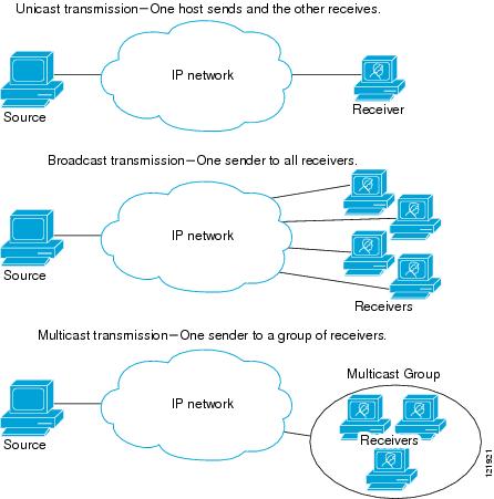
IP communication consists of hosts that act as senders and receivers of traffic as shown in the first figure. Senders are
called sources. Traditional IP communication is accomplished by a single host source sending packets to another single host
(unicast transmission) or to all hosts (broadcast transmission). With IP multicast, you can send packets to a specific group
of hosts instead of all hosts (multicast transmission). This subset, comprising receiving hosts, is called a multicast group.
The hosts that belong to a multicast group are called group members.
Multicast is based on this group concept. A multicast group consists of receivers joining a group to receive a specific data
stream. This multicast group has no physical or geographical boundaries--the hosts can be located anywhere on the Internet
or on any private internetwork. Hosts interested in receiving data to a particular group must join the group from the source.
A host receiver joins a group using the Internet Group Management Protocol (IGMP).
In a multicast environment, any host, regardless of whether it is a member of a group, can send to a group. Only members
of a group receive packets sent to that group. Multicast packets, like IP unicast packets, use best-effort reliability for
delivery.
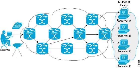
In the next figure, the receivers (the designated multicast group) are interested in receiving the video data stream from
the source. The receivers indicate their interest by sending an IGMP host report to the routers in the network. The routers
are then responsible for delivering the data from the source to the receivers. The routers use Protocol Independent Multicast
(PIM) to dynamically create a multicast distribution tree. The video data stream will then be delivered only to the network
segments that are in the path between the source and the receivers.
Source specific multicast
Source Specific Multicast (SSM) is a datagram delivery model that effectively supports one-to-many applications, also known
as broadcast applications. SSM is a core network technology in the Cisco implementation of IP multicast, aimed at audio and
video broadcast application environments.
For the SSM delivery mode, an IP multicast receiver host must use IGMP Version 3 (IGMPv3) to subscribe to channel (S,G).
By subscribing to this channel, the receiver host indicates a desire to receive IP multicast traffic sent by source host S
to group G. The network will deliver IP multicast packets from source host S to group G to all hosts in the network that have
subscribed to the channel (S, G).
SSM does not require group address allocation within the network, only within each source host. Different applications running
on the same source host must use different SSM groups. Applications on different source hosts can reuse SSM group addresses
without causing excess network traffic.
IP multicast routing protocols
The software supports these protocols to implement IP multicast routing:
IGMP is used between hosts on a LAN and the routers (and multilayer devices) on that LAN to track the multicast groups of
which hosts are members. To participate in IP multicasting, multicast hosts, routers, and multilayer devices must have the
Internet Group Management Protocol (IGMP) operating.
PIM is used between routers to track which multicast packets to forward to other routers and their directly connected LANs.
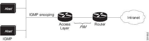
IGMP Snooping is used for multicasting in a Layer 2 switching environment. It reduces multicast traffic flooding by dynamically
configuring Layer 2 interfaces to forward traffic only to interfaces associated with IP multicast devices.
The figure illustrates the role of each protocol within the IP multicast environment.
Figure 1. IP multicast routing protocols
According to IPv4 multicast standards, the MAC destination multicast address begins with 0100:5e and is appended by the last
23 bits of the IP address. For example, if the IP destination address is 239.1.1.39, the MAC destination address is 0100:5e01:0127.
When the destination IPv4 address differs from the destination MAC address, a multicast packet is considered unmatched. The
device forwards the unmatched packet in hardware based upon the MAC address table. If the destination MAC address is absent
from the MAC address table, the device will flood the packet to all ports within the VLAN of the receiving port.
Internet group management protocol
IGMP messages are used by IP multicast hosts to send their local Layer 3 switch or router a request to join a specific multicast
group and begin receiving multicast traffic. With extensions in IGMPv2, IP hosts can request a Layer 3 switch or router to
leave an IP multicast group and cease receiving the multicast group traffic.
A Layer 3 switch or router maintains a list of multicast group memberships on a per-interface basis using the information
obtained by IGMP. Multicast group membership stays active on an interface if a host on that interface sends an IGMP request
for multicast group traffic.
Protocol-independent multicast
Protocol-Independent Multicast (PIM) leverages whichever unicast routing protocol you use to populate the unicast routing
table, including EIGRP, OSPF, or static route, to support IP multicast.
PIM performs the reverse path forwarding (RPF) check using a unicast routing table, avoiding the need for a separate multicast
routing table. PIM does not send and receive multicast routing updates between routers like other routing protocols do.
PIM sparse mode
PIM Sparse Mode (PIM-SM) delivers multicast traffic only to networks with active receivers that request the data explicitly.
PIM-SM is intended for networks featuring several different multicast activities, including desktop video conferencing and
collaborative computing, targeting a small number of receivers and occurring simultaneously.
Rendezvous point
If you configure PIM to operate in sparse mode, choose one or more devices to be rendezvous points (RPs). Senders in a multicast
group use RPs to register their activity, while receivers use them to learn about new senders. You can configure Cisco IOS
software so that packets for a single multicast group can use one or more RPs.
RP addresses allow first hop devices to send PIM register messages on behalf of a host sending a packet to the group. The
RP address is also used by last hop devices to send PIM join and prune messages to the RP to inform it about group membership.
Configure the RP address on all devices (including the RP device).
A PIM device can be an RP for more than one group. Only one RP address can be used at a time within a PIM domain for the same
group. The access list conditions determine which groups the device is an RP for; different groups can have different RPs.
IGMP snooping
Use IGMP snooping for multicasting in a Layer 2 switching environment. With IGMP snooping, a Layer 3 switch or router examines
Layer 3 information in the IGMP packets in transit between hosts and a device. When you receive the IGMP Host Report, add
the host's port number to the multicast table entry. When you receive the IGMP Leave Group message, remove the port from the
table entry.
IGMP control messages, transmitted as multicast packets, resemble multicast data when examining only the Layer 2 header. A
switch running IGMP snooping examines every multicast data packet to determine whether it contains any pertinent IGMP control
information. Implement IGMP snooping on a switch with a strong CPU to maintain performance even at high data transmission
rates.
IP multicast addressing and scoping
This section describes about IP multicast addressing and its supported range of addresses.
IP multicast group addressing
A multicast group is identified and addressed by its multicast group address, which multicast packets are delivered to. Unlike
unicast addresses, which identify a single host, multicast IP addresses do not specify a particular host. To receive the data
sent to a multicast address, a host must join the group that address identifies. The data is sent to the multicast address
and received by all the hosts that have joined the group. This indicates that they wish to receive traffic sent to that group.
The source assigns the multicast group address to a group. Network administrators must ensure multicast group addresses conform
to the address range reserved by the Internet Assigned Numbers Authority (IANA).
Note
Simple Service Discovery Protocol (SSDP) group IP 239.255.255.250 is blocked by default. To use this group IP, configure the
platform ip multicast ssdp command.
IP class D addresses
IP multicast addresses have been assigned to the IPv4 Class D address space by IANA. The high-order four bits of a Class
D address are 1110. Host group addresses are in the range 224.0.0.0 to 239.255.255.255. The source chooses a multicast address
for the receivers in a multicast group.
Note
Use the Class D address range only as the group or destination address of IP multicast traffic. The source for multicast
datagrams is always a unicast address.
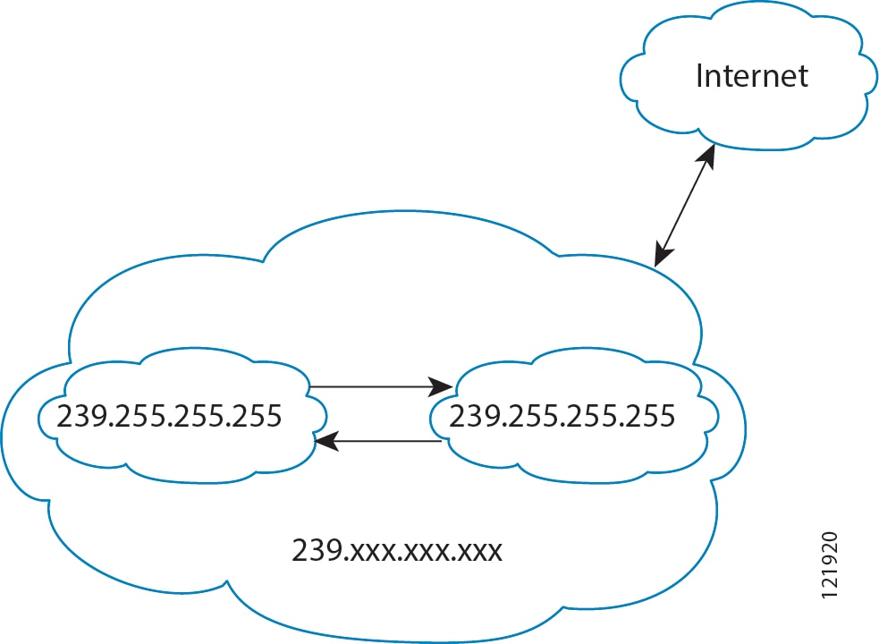
IP multicast boundary
The figure illustrates how address scoping defines domain boundaries to prevent domains, each with RPs sharing the same IP
address, from leaking into one another. Scoping is performed on the subnet boundaries within large domains and on the boundaries
between the domain and the Internet.
Figure 2. Address scoping at boundaries
Select the ipmulticastboundary command with the access-list to set up an administratively scoped boundary on an interface. A standard access list defines the range of addresses affected.
Boundaries prevent multicast data packets from flowing across in either direction. The boundary allows the same multicast
group address to be reused in different administrative domains.
The Internet Assigned Numbers Authority (IANA) has designated the multicast address range 239.0.0.0 to 239.255.255.255 as
the administratively scoped addresses. This range of addresses can be reused in domains administered by different organizations.
These addresses are considered local rather than globally unique.
You can configure the filter-autorp keyword to examine and filter Auto-RP discovery and announcement messages at the administratively scoped boundary. Any Auto-RP
group range announcements from the Auto-RP packets that are denied by the boundary access control list (ACL) are removed.
Auto-RP group range announcements are permitted and passed by the boundary only if all addresses in the Auto-RP group range
are permitted by the boundary ACL. If any address is not permitted, the entire group range is filtered and removed from the
Auto-RP message before the Auto-RP message is forwarded.
IP multicast address scoping
The multicast address range is subdivided to provide predictable behavior and enable address reuse within smaller domains.
The table provides a summary of the multicast address ranges and each range is briefly described.
Table 1. Multicast address range assignments
Name
Range
Description
Reserved link-local addresses
224.0.0.0 to 224.0.0.255
Reserved for use by network protocols on a local network segment.
Globally scoped addresses
224.0.1.0 to 238.255.255.255
Reserved to send multicast data between organizations and across the Internet.
Source specific multicast
232.0.0.0 to 232.255.255.255
Reserved for use with the SSM datagram delivery model where data is forwarded only to receivers that have explicitly joined
the group.
GLOP addresses
233.0.0.0 to 233.255.255.255
Reserved for statically defined addresses by organizations that already have an assigned autonomous system (AS) domain number.
Limited scope address
239.0.0.0 to 239.255.255.255
Reserved as administratively or limited scope addresses for use in private multicast domains.
Reserved link-local addresses
The IANA has reserved the range 224.0.0.0 to 224.0.0.255 for use by network protocols on a local network segment. IP routers
do not forward packets within this range which are local in scope. Typically, packets with link local destination addresses
are sent with a TTL value of 1 and remain unforwarded by routers.
Reserved link-local addresses serve network protocol functions. Network protocols use these addresses for automatic router
discovery and to communicate important routing information. For example, Open Shortest Path First (OSPF) uses the IP addresses
224.0.0.5 and 224.0.0.6 to exchange link-state information.
IANA assigns single multicast address requests for network protocols or network applications out of the 224.0.1.xxx address
range. Multicast routers forward these multicast addresses.
Globally scoped addresses
Addresses in the range 224.0.1.0 to 238.255.255.255 are called globally scoped addresses. These addresses are used to send
multicast data between organizations across the Internet. Some of these addresses have been reserved by IANA for use by multicast
applications. For example, the IP address 224.0.1.1 is reserved for Network Time Protocol (NTP).
Source specific multicast addresses
Addresses in the range 232.0.0.0/8 are reserved for Source Specific Multicast (SSM) by IANA. Use the ippimssm command to configure SSM for arbitrary IP multicast addresses also. SSM is an extension of PIM that allows for an efficient
data delivery mechanism in one-to-many communications.
GLOP addresses
GLOP addressing, as proposed by RFC 2770, reserves the 233.0.0.0/8 range for organizations with a reserved AS number for
statically defined addresses. This practice is called GLOP addressing. The AS number of the domain is embedded into the second
and third octets of the 233.0.0.0/8 address range. For example, AS 62010 is written in hexadecimal format as F23A. Separating
the two octets F2 and 3A results in 242 and 58 in decimal format. These values result in a subnet of 233.242.58.0/24 that
would be globally reserved for AS 62010 to use.
Limited scope addresses
The range 239.0.0.0 to 239.255.255.255 is reserved as administratively or limited scoped addresses for use in private multicast
domains. These addresses are constrained to a local group or organization. Companies, universities, and other organizations
can use limited scope addresses to have local multicast applications that will not be forwarded outside their domain. Routers
typically are configured with filters to prevent multicast traffic in this address range from flowing outside an autonomous
system (AS) or any user-defined domain. Within an AS or domain, the limited scope address range can be further subdivided
so that local multicast boundaries can be defined.
Note
Network administrators may use multicast addresses in this range, inside a domain, without conflicting with others elsewhere
in the Internet.
Layer 2 multicast addresses
Historically, network interface cards (NICs) on a LAN segment only received packets destined for their burned-in MAC address
or the broadcast MAC address. In IP multicast, several hosts need to be able to receive a single data stream with a common
destination MAC address. Some means had to be devised so that multiple hosts could receive the same packet and differentiate
between several multicast groups. One method to achieve this is mapping IP multicast Class D addresses directly to a MAC address.
With this method, NICs can receive packets destined for many different MAC addresses.
Cisco Group Management Protocol (CGMP) is used on routers connected to Catalyst switches to perform tasks similar to those
performed by IGMP. CGMP is necessary for those Catalyst switches that cannot distinguish between IP multicast data packets
and IGMP report messages, both of which are addressed to the same group address at the MAC level.
IP multicast forwarding and routing
This section describes about multicast packet forwarding and routing.
IP multicast tables
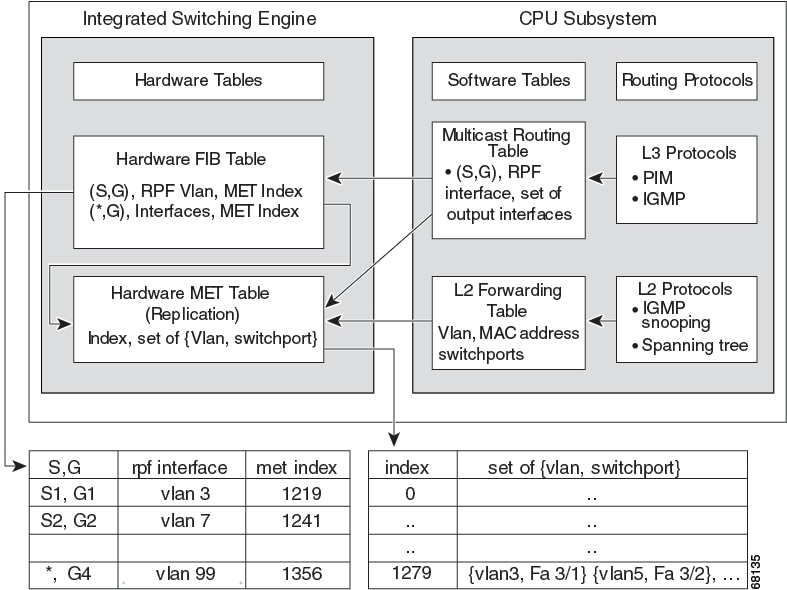
This illustration presents key data structures used by the device to forward IP multicast packets in hardware.
Figure 3. IP multicast tables and protocols
The Integrated Switching Engine maintains the hardware FIB table to identify individual IP multicast routes. Each entry consists
of a destination group IP address and an optional source IP address. Multicast traffic flows on primarily two types of routes:
(S,G) and (*,G). The (S,G) routes flow from a source to a group based on the IP address of the multicast source and the IP
address of the multicast group destination. Traffic on a (*,G) route flows from the PIM RP to all receivers of group G. Sparse-mode
groups are the only ones that use (*,G) routes. The Integrated Switching Engine hardware supports 128,000 routes shared by
unicast, multicast, and multicast fast-drop entries.
The multicast expansion table (MET) stores output interface lists. The MET has room for up to 32,000 output interface lists.
(For RET, we can have up to 102 K entries (32 K used for floodsets, 70,000 used for multicast entries)). The MET resources
are shared by both Layer 3 multicast routes and by Layer 2 multicast entries. The actual number of output interface lists
available in hardware depends on the specific configuration. If the total number of multicast routes exceeds 32,000, the Integrated
Switching Engine might not switch the multicast packets. They would be forwarded by the CPU subsystem at much slower speeds.
Note
For RET, a maximum of 102 K entries is supported (32 K used for floodsets, 70 K used for multicast entries).
Hardware and software forwarding
The Integrated Switching Engine forwards most packets in hardware at high speeds. The CPU subsystem forwards exception packets
in software. Statistical reports show that the Integrated Switching Engine forwards most packets in hardware.
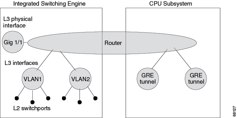
This illustration shows a logical view of the hardware and software forwarding components.
Figure 4. Hardware and software forwarding components
In the normal mode of operation, the Integrated Switching Engine performs inter-VLAN routing in hardware.
Replication is a type of forwarding in which the packet is duplicated, and multiple copies are sent out instead of a single
copy. Replication occurs only for multicast packets at Layer 3; unicast packets are never replicated to multiple Layer 3 interfaces.
In IP multicasting, for each incoming IP multicast packet that is received, many replicas of the packet are sent out.
IP multicast packets can be transmitted on the following types of routes:
Hardware routes
Software routes
Partial routes
Hardware routes occur when all packet replicas are forwarded by the Integrated Switching Engine. Software routes occur when
all packet replicas are forwarded by the CPU subsystem. Partial routes occur when some replicas are forwarded by the Integrated
Switching Engine, and others are forwarded by the CPU subsystem.
Partial routes
These conditions prompt the CPU subsystem software to forward replicas of a packet; however, they do not affect the performance
of replicas forwarded in hardware.
The switch is configured with the ip igmp join-group command as a member of the IP multicast group on the RPF interface of the multicast source.
The switch is the first-hop to the source in PIM sparse mode. The switch must send PIM-register messages to the RP.
Software routes
Note
If a condition is set on either the RPF interface or the output interface, output replication is conducted in the software.
These conditions cause all replicas of a packet for a route to be forwarded by the CPU subsystem software:
The interface is configured with multicast helper.
The interface uses non-Advanced Research Products Agency (ARPA) encapsulation.
These packets are always forwarded in software:
Packets sent to multicast groups that fall into the range 224.0.0.* (where * is in the range from 0 to 255). This range is
used by routing protocols. Layer 3 switching supports all other multicast group addresses.
Packets with IP options.
Static multicast route
Static multicast routes (mroutes) calculate RPF information but do not forward traffic, cannot be redistributed, and are strictly
local to the device they are defined on.
Because Protocol Independent Multicast (PIM) does not have its own routing protocol, there is no mechanism to distribute static
mroutes throughout the network. Static mroutes require careful attention during administration compared to unicast static
routes.
When static mroutes are configured, they are stored on the device in a separate table called the static mroute table. When
configured, the ip mroute command enters a static mroute into the static mroute table for the source address or source address range specified for
the source-address and mask arguments. Sources matching the specified source address range will perform RPF checks on either
the interface associated with the specified IP address for the rpf-address argument or the local interface specified for the interface-type and interface-number arguments. If an IP address is specified for the rpf-address argument, the device performs a recursive lookup from the unicast routing table on this address to find the directly connected
neighbor.
When multiple static mroutes are configured, the device performs a longest-match lookup of the mroute table. When the mroute
with the longest match of the source-address is found, the search terminates, and the static mroute's matching information
is utilized. The order in which static mroutes are configured is not important.
You can specify the administrative distance of an mroute with the optional distance argument. If you do not specify a value
for the distance argument, the distance of the mroute defaults to zero. If the static mroute has the same distance as another
RPF source, the static mroute will take precedence. There are only two exceptions to this rule: directly connected routes
and the default unicast route.
Non-reverse path forwarding traffic
Traffic failing a Reverse Path Forwarding (RPF) check is called non-RPF traffic. Non-RPF traffic is forwarded by the Integrated
Switching Engine by filtering (persistently dropping) or rate limiting the non-RPF traffic.
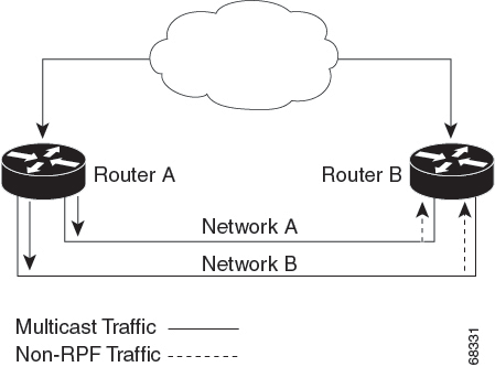
In a redundant configuration where multiple Layer 3 switches or routers connect to the same LAN segment, only one device forwards
the multicast traffic from the source to the receivers on the outgoing interfaces. This network configuration can result in
non-RPF traffic.
Figure 5. Redundant multicast router configuration in a stub network
In this kind of topology, only Router A, the PIM designated router (PIM DR), forwards data to the common VLAN. Router B receives
the forwarded multicast traffic, but must drop this traffic because it has arrived on the wrong interface and fails the RPF
check. Traffic that does not pass the RPF check is known as non-RPF traffic.
Multicast forwarding information base
The Multicast Forwarding Information Base (MFIB) is a multicast routing protocol independent forwarding engine that does not
depend on PIM or any other multicast routing protocol. It is responsible for:
Forwarding multicast packets
Registering with the MRIB to learn the entry and interface flags set by the control plane
Handling data-driven events that must be sent to the control plane
Maintaining counts, rates, and bytes of received, dropped, and forwarded multicast packets
MFIB subsystem supports IP multicast routing in the Integrated Switching Engine hardware on Cisco devices. The MFIB resides
logically between the IP multicast routing protocols in the CPU subsystem software and the platform-specific code that manages
IP multicast routing in hardware. The MFIB simplifies routing table information for processing and forwarding by the Integrated
Switching Engine hardware.
To view multicast routing table information, use the show ip mroute command. To display the MFIB table information, use the show ip mfib command.
The MFIB table has IP multicast routes like (S,G) and (*,G). Each route in the MFIB table can have one or more optional flags
associated with it. The route flags indicate how a packet that matches a route should be forwarded. The Internal Copy (IC)
flag on an MFIB route indicates that a switch process needs to receive a copy of the packet, for example. These flags can
be associated with MFIB routes:
Internal Copy (IC) flag: Sets on a route when a process on the router needs to receive packets matching the specified route.
Signalling (S) flag: Sets on a route when a process needs to be notified when a packet matching the route is received; the
expected behavior is that the protocol code updates the MFIB state in response to receiving a packet on a signalling interface.
Connected (C) flag: When set on an MFIB route, the C flag means that packets from directly connected hosts are signaled to
a protocol process, similar to the Signaling (S) flag.
A route can also have a set of optional flags associated with one or more interfaces. For example, an (S,G) route with the
flags on VLAN 1 indicates how packets arriving on VLAN 1 should be handled, and whether packets matching the route should
be forwarded onto VLAN 1. The per-interface flags supported in the MFIB include the following:
Accepting (A): Sets on the interface that is known in multicast routing as the RPF interface. A packet that arrives on an
interface that is marked as Accepting (A) is forwarded to all Forwarding (F) interfaces.
Forwarding (F): Used in conjunction with the Accepting (A) flag as described above. The set of Forwarding interfaces that
form what is often referred to as the multicast “olist” or output interface list.
Signaling (S): Sets on an interface when some multicast routing protocol process in Cisco IOS needs to be notified of packets
arriving on that interface.
Note
When PIM-SM routing is in use, the MFIB route might include an interface as in this example:
PimTunnel [1.2.3.4]
It is a virtual interface that the MFIB subsystem creates to indicate that packets are being tunnelled to the specified destination
address. A PimTunnel interface cannot be displayed with the normal show interface command.
S/M 224/4 MFIB entry
An (S/M, 224/4) entry is created in the MFIB for every multicast-enabled interface. This entry ensures that all packets sent
by directly connected neighbors are encapsulated and sent to the PIM-SM RP. You can forward a small number of packets using
the (S/M,224/4) route until the (S,G) route is established by PIM-SM.
For example, on an interface with IP address 10.0.0.1 and a netmask of 255.0.0.0, a route is created to match all IP multicast
packets where the source address is any address in the class A network 10. This route can be written in conventional subnet/masklength
notation as (10/8,224/4). If an interface has multiple assigned IP addresses, one route is created for each IP address.
Cisco express forwarding, MFIB, and Layer 2 forwarding
The implementation of IP multicast is an extension of centralized Cisco Express Forwarding. Cisco Express Forwarding extracts
information from the unicast routing table, which is created by unicast routing protocols, such as BGP, OSPF, and EIGRP and
loads it into the hardware
Forwarding Information Base (FIB). With the unicast routes in the FIB, when a route is changed in the upper-layer routing
table, only one route needs to be changed in the hardware routing state. To forward unicast packets in hardware, the Integrated
Switching Engine looks up source and destination routes in ternary content addressable memory (TCAM), takes the adjacency
index from the hardware FIB, and gets the Layer 2 rewrite information and next-hop address from the hardware adjacency table.
The new Multicast Forwarding Information Base (MFIB) subsystem is the multicast analog of the unicast Cisco Express Forwarding.
The MFIB subsystem extracts the multicast routes that PIM and IGMP create and refines them into a protocol-independent format
for forwarding in hardware. The MFIB subsystem removes the protocol-specific information and leaves only the essential forwarding
information.
Each entry in the MFIB table consists of an (S,G) or (*,G) route, an input RPF VLAN, and a list of Layer 3 output interfaces.
The MFIB subsystem, together with platform-dependent management software, loads this multicast routing information into the
hardware FIB and Replica Expansion Table (RET). The device performs Layer 3 routing and Layer 2 bridging at the same time.
There can be multiple Layer 2 switch ports on any VLAN interface.
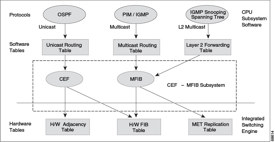
The following illustration shows a functional overview of how a Cisco device combines unicast routing, multicast routing,
and Layer 2 bridging information to forward in hardware:
Figure 6. Combining Cisco express forwarding, MFIB, and Layer 2 forwarding information in hardware
Like the Cisco Express Forwarding unicast routes, the MFIB routes are Layer 3 and must be merged with the appropriate Layer
2 information. The following example shows an MFIB route:
The route (*,203.0.113.1) is loaded in the hardware FIB table and the list of output interfaces is loaded into the MET. A
pointer to the list of output interfaces, the MET index, and the RPF interface are also loaded in the hardware FIB with the
(*,203.0.113.1) route. With this information loaded in hardware, merging of the Layer 2 information can begin. For the output
interfaces on VLAN1, the Integrated Switching Engine must send the packet to all switch ports in VLAN1 that are in the spanning
tree forwarding state. The same process applies to VLAN 2. To determine the set of switch ports in VLAN 2, the Layer 2 Forwarding
Table is used.
When the hardware routes a packet, in addition to sending it to all of the switch ports on all output interfaces, the hardware
also sends the packet to all switch ports (other than the one it arrived on) in the input VLAN. For example, assume that VLAN
3 has two switch ports in it, GigabitEthernet 3/1 and GigabitEthernet 3/2. If a host on GigabitEthernet 3/1 sends a multicast
packet, the host on GigabitEthernet 3/2 might also need to receive the packet. To send a multicast packet to the host on GigabitEthernet
3/2, all of the switch ports in the ingress VLAN must be added to the port set that is loaded in the MET.
If VLAN 1 contains 1/1 and 1/2, VLAN 2 contains 2/1 and 2/2, and VLAN 3 contains 3/1 and 3/2, the MET chain for this route
would contain these switch ports: (1/1,1/2,2/1,2/2,3/1, and 3/2).
If IGMP snooping is on, the packet should not be forwarded to all output switch ports on VLAN 2. The packet should be forwarded
only to switch ports where IGMP snooping has determined that there is either a group member or router. For example, if VLAN
1 had IGMP snooping enabled, and IGMP snooping determined that only port 1/2 had a group member on it, then the MET chain
would contain these switch ports: (1/1,1/2, 2/1, 2/2, 3/1, and 3/2).
Multicast fast drop
In IP multicast protocols, such as PIM-SM, every (S,G) or (*,G) route has an incoming interface associated with it. This interface
is called the reverse path forwarding interface. In some cases, when a packet arrives on an interface other than the expected
RPF interface, the packet must be forwarded to the CPU subsystem software to allow PIM to perform special protocol processing
on the packet. One example of this special protocol processing that PIM performs is the PIM Assert protocol.
By default, the Integrated Switching Engine hardware sends all packets that arrive on a non-RPF interface to the CPU subsystem
software. However, processing in software is not necessary in many cases, because these non-RPF packets are often not needed
by the multicast routing protocols. Non-RPF packets sent to the software can overwhelm the CPU if their processing is not
managed.
Instead of installing fast-drop entries, the Cisco device uses Dynamic Buffer Limiting (DBL). This flow-based congestion avoidance
mechanism provides active queue management by tracking the queue length for each traffic flow. When the queue length of a
flow exceeds its set limit, DBL drops packets. Rate DBL limits the non-RPF traffic to the CPU subsystem so that the CPU is
not overwhelmed. The packets are rate limited per flow to the CPU. Because installing fast-drop entries in the CAM is inaccessibly,
the number of fast-drop flows that can be handled by the switch need not be limited.
Protocol events, such as a link going down or a change in the unicast routing table, can impact the set of packets that can
safely be fast dropped. After a topology change, packets that were previously fast-dropped might require forwarding to the
CPU subsystem for proper PIM processing. The CPU subsystem software handles flushing fast-drop entries in response to protocol
events so that the PIM code in IOS can process all the necessary RPF failures.
The use of fast-drop entries in the hardware is critical in some common topologies because you may have persistent RPF failures.
Without the fast-drop entries, the CPU is exhausted by RPF failed packets that it did not need to process.
Multicast high availability
The device supports multicast high availability, ensuring continuous multicast traffic flow in case of a supervisor engine
failure. MFIB states are synced to the standby supervisor engine before a switchover, ensuring NSF availability with a fast
convergence upon switchover during a supervisor engine failure.
Multicast HA (SSO / NSF / ISSU) is supported for the PIM Sparse mode, SSM mode, and in Layer 2 for IGMP and MLD Snooping.
Default IP multicast routing configuration
This table displays the default IP multicast routing configuration.
Table 2. Default IP multicast routing configuration
Feature
Default Setting
Multicast routing
Disabled on all interfaces.
PIM version
Version 2.
PIM mode
No mode is defined.
PIM stub routing
None configured.
PIM RP address
None configured.
PIM domain border
Disabled.
PIM multicast boundary
None.
Candidate BSRs
Disabled.
Candidate RPs
Disabled.
Shortest-path tree threshold rate
0 kb/s.
PIM router query message interval
30 seconds.
Configure basic IP multicast routing
This section provides information about configuring basic IP multicast routing.
Configure basic IP multicast routing
Before you begin
Note
By default, multicast routing is disabled, and there is no default mode setting. To enable multicast routing, use the ip multicast-routing command.
You must configure the PIM version and the PIM mode. The switch populates its multicast routing table and forwards multicast
packets it receives from its directly connected LANs according to the mode setting.
In populating the multicast routing table, dense-mode interfaces are always added to the table. Sparse-mode interfaces are
added to the table only when periodic join messages are received from downstream devices or when there is a directly connected
member on the interface. Sparse-mode operation occurs if there is an RP known for the group when forwarding from a LAN. Packets
are then encapsulated and sent toward the RP. Without a known RP, the packet is flooded in a dense-mode fashion. For both
PIM dense mode and PIM any-source multicast mode, the multicast source address must be on the directly connected incoming
interface within the same subnet of the first-hop router. If the multicast traffic from a specific source is sufficient, the
receiver’s first-hop router will send join messages toward the source to build a source-based distribution tree.
Procedure
Command or Action
Purpose
Step 1
enable
Example:
Device> enable
Enables privileged EXEC mode.
Enter your password, if prompted.
Step 2
configureterminal
Example:
Device# configure terminal
Enters global configuration mode.
Step 3
ip multicast-routing
Example:
Device(config)# ip multicast-routing
Enables IP multicast routing.
IP multicast routing is supported with Multicast Forwarding Information Base (MFIB) and Multicast Routing Information Base
(MRIB).
Step 4
interfaceinterface-id
Example:
Device(config)# interface gigabitethernet 1/0/1
Specifies the Layer 3 interface on which you want to enable multicast routing, and enters interface configuration mode.
The specified interface must be one of the following:
A routed port: A physical port configured as a Layer 3 port by entering the no switchport interface configuration command. You will also need to enable IP PIM sparse-dense-mode on the interface and join the interface
as a static IGMP group member.
An SVI: A VLAN interface created by using the interface vlanvlan-id global configuration command. You will also need to enable IP PIM sparse-dense-mode on the VLAN, join the VLAN as a statically
connected member to an IGMP static group, and then enable IGMP snooping on the VLAN, the IGMP static group, and physical interface.
These interfaces must have IP addresses assigned to them.
Step 5
ip pim {dense-mode | sparse-mode | sparse-dense-mode}
Example:
Device(config-if)# ip pim sparse-mode
Enables a PIM mode on the interface.
By default, no mode is configured. The keywords have these meanings:
dense-mode: Enables dense mode of operation.
sparse-mode: Enables sparse mode of operation. If you configure sparse mode, you must also configure an RP.
sparse-dense-mode: Causes the interface to be treated in the mode in which the group belongs. Sparse-dense mode is the recommended setting.
Note
To disable PIM on an interface, use the no ip pim interface configuration command.
Step 6
end
Example:
Device(config-if)# end
Returns to privileged EXEC mode.
Step 7
show running-config
Example:
Device# show running-config
Verifies your entries.
Step 8
copy running-config startup-config
Example:
Device# copy running-config startup-config
(Optional) Saves your entries in the configuration file.
Device(config)# ip mroute 10.1.1.1 255.255.255.255 10.2.2.2
The source IP address 10.1.1.1 is accessible via the interface linked to IP address 10.2.2.2.
Step 4
exit
Example:
Device(config)# exit
Returns to privileged EXEC mode.
Step 5
show running-config
Example:
Device# show running-config
(Optional) Verifies your entries.
Step 6
copy running-config startup-config
Example:
Device# copy running-config startup-config
(Optional) Saves your entries in the configuration file.
Enable sdr listener support
By default, the device does not listen to session directory advertisements. This procedure is optional.
Procedure
Command or Action
Purpose
Step 1
enable
Example:
Device> enable
Enables privileged EXEC mode.
Enter your password, if prompted.
Step 2
configure terminal
Example:
Device# configure terminal
Enters global configuration mode.
Step 3
interfaceinterface-id
Example:
Device(config)# interface gigabitethernet 1/0/1
Specifies the interface to be enabled for sdr, and enters interface configuration mode.
Step 4
ip sap listen
Example:
Device(config-if)# ip sap listen
Enables the device software to listen to session directory announcements.
Step 5
end
Example:
Device(config-if)# end
Returns to privileged EXEC mode.
Step 6
show running-config
Example:
Device# show running-config
Verifies your entries.
Step 7
copy running-config startup-config
Example:
Device# copy running-config startup-config
(Optional) Saves your entries in the configuration file.
Limit sdr cache entry
Entries are retained indefinitely in the sdr cache by default. You can limit how long the entry remains active so that if
a source stops advertising SAP information, old advertisements are not unnecessarily kept.
This procedure is optional.
Procedure
Command or Action
Purpose
Step 1
enable
Example:
Device> enable
Enables privileged EXEC mode.
Enter your password, if prompted.
Step 2
configure terminal
Example:
Device# configure terminal
Enters global configuration mode.
Step 3
ip sap cache-timeoutminutes
Example:
Device(config)# ip sap cache-timeout 30
Limits how long a Session Announcement Protocol (SAP) cache entry stays active in the cache.
By default, entries are never deleted from the cache.
For minutes, the range is 1 to 1440 minutes (24 hours).
Step 4
end
Example:
Device(config)# end
Returns to privileged EXEC mode.
Step 5
show running-config
Example:
Device# show running-config
Verifies your entries.
Step 6
show ip sap
Example:
Device# show ip sap
Displays the SAP cache.
Step 7
copy running-config startup-config
Example:
Device# copy running-config startup-config
(Optional) Saves your entries in the configuration file.
Monitor and maintain basic IP multicast routing
The commands in this section can be used to monitor and maintain basic IP multicast routing.
Clear caches, tables, and databases
You can remove all contents of a particular cache, table, or database. Clearing a cache, table, or database might be necessary
when the contents of the particular structure are or suspected to be invalid.
You can use any of the privileged EXEC commands in the following table to clear IP multicast caches, tables, and databases.
Table 3. Commands for clearing caches, tables, and databases
Command
Purpose
clear ip igmp group {group [ hostname | IP address] | vrfnamegroup [ hostname | IP address] }
Deletes entries from the IGMP cache.
clear ip mfib { counters [group | source] | global counters [group | source] | vrf * }
Clears all active IPv4 Multicast Forwarding Information Base (MFIB) traffic counters.
clear ip mrm {status-report [ source ] }
Clears IP multicast routing monitor status reports.
clear ip mroute { * | [hostname | IP address] | vrfnamegroup [ hostname | IP address] }
Deletes entries from the IP multicast routing table.
The software processes mrinfo requests from mrouted systems, Cisco routers, and multilayer devices. It provides information
about neighbors via DVMRP tunnels and routed interfaces. This information includes the metric (always set to 1), the configured
TTL threshold, the status of the interface, and various flags. You can also use the mrinfo privileged EXEC command to query the router or device itself, as in this example:

 Feedback