-
- Administration User Interface Reference
- Guest Access User Interface Reference
- Web Portals Customization Reference
- Policy User Interface Reference
- Operations User Interface Reference
- Network Access Flows
- Switch and Wireless LAN Controller Configuration Required to Support Cisco ISE Functions
- Supported Management Information Bases in Cisco ISE
- TrustSec Architecture
- Configure TrustSec Global Settings
- Configure TrustSec Devices
- Configure TrustSec AAA Servers
- Security Groups Configuration
- Egress Policy
- Egress Policy Table Cells Configuration
- Configure SGT from Egress Policy
- Monitor Mode
- Push Button
Cisco TrustSec Policies Configuration
TrustSec Architecture
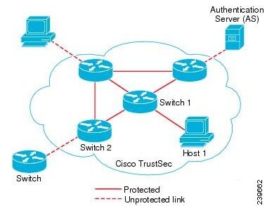
The Cisco TrustSec solution establishes clouds of trusted network devices to build secure networks. Each device in the Cisco TrustSec cloud is authenticated by its neighbors (peers). Communication between the devices in the TrustSec cloud is secured with a combination of encryption, message integrity checks, and data-path replay protection mechanisms. The TrustSec solution uses the device and user identity information that it obtains during authentication to classify, or color, the packets as they enter the network. This packet classification is maintained by tagging packets when they enter the TrustSec network so that they can be properly identified for the purpose of applying security and other policy criteria along the data path. The tag, also called the security group tag (SGT), allows Cisco ISE to enforce access control policies by enabling the endpoint device to act upon the SGT to filter traffic.
The following figure shows an example of a TrustSec network cloud.
TrustSec Components
The key TrustSec components include:
-
Network Device Admission Control (NDAC)—In a trusted network, during authentication, each network device (for example Ethernet switch) in a TrustSec cloud is verified for its credential and trustworthiness by its peer device. NDAC uses the IEEE 802.1X port-based authentication and uses Extensible Authentication Protocol-Flexible Authentication via Secure Tunneling (EAP-FAST) as its Extensible Authentication Protocol (EAP) method. Successful authentication and authorization in the NDAC process results in Security Association Protocol negotiation for IEEE 802.1AE encryption.
-
Endpoint Admission Control (EAC)—An authentication process for an endpoint user or a device connecting to the TrustSec cloud. EAC typically happens at the access level switch. Successful authentication and authorization in EAC process results in SGT assignment to the user or device. EAC access methods for authentication and authorization includes:
-
Security Group (SG)—A grouping of users, endpoint devices, and resources that share access control policies. SGs are defined by the administrator in Cisco ISE. As new users and devices are added to the TrustSec domain, Cisco ISE assigns these new entities to the appropriate security groups.
-
Security Group Tag (SGT)—TrustSec service assigns to each security group a unique 16-bit security group number whose scope is global within a TrustSec domain. The number of security groups in the switch is limited to the number of authenticated network entities. You do not have to manually configure security group numbers. They are automatically generated, but you have the option to reserve a range of SGTs for IP-to-SGT mapping.
-
Security Group Access Control List (SGACL)—SGACLs allow you to control the access and permissions based on the SGTs that are assigned. The grouping of permissions into a role simplifies the management of security policy. As you add devices, you simply assign one or more security groups, and they immediately receive the appropriate permissions. You can modify the security groups to introduce new privileges or restrict current permissions.
-
Security Exchange Protocol (SXP)—SGT Exchange Protocol (SXP) is a protocol developed for TrustSec service to propagate the IP-SGT bindings across network devices that do not have SGT-capable hardware support to hardware that supports SGT/SGACL.
-
Environment Data Download—The TrustSec device obtains its environment data from Cisco ISE when it first joins a trusted network. You can also manually configure some of the data on the device. The device must refresh the environment data before it expires. The TrustSec device obtains the following environment data from Cisco ISE:
-
SGT Reservation—An enhancement in Cisco ISE to reserve a range of SGTs to enable IP to SGT mapping.
-
IP-to-SGT Mapping—An enhancement in Cisco ISE to bind an endpoint IP to an SGT and provision it to a TrustSec-capable device. Cisco ISE supports entering 1000 IP-to-SGT Mappings.
-
Identity-to-Port Mapping—A method for a switch to define the identity on a port to which an endpoint is connected, and to use this identity to look up a particular SGT value in the Cisco ISE server.
TrustSec Terminology
The following table lists some of the common terms that are used in the TrustSec solution and their meaning in an TrustSec environment.
Supported Switches and Required Components for TrustSec
To set up a Cisco ISE network that is enabled with the Cisco TrustSec solution, you need switches that support the TrustSec solution and other components. Apart from the switches, you also need other components for identity-based user access control using the IEEE 802.1X protocol. For a complete up-to-date list of the Trustsec-supported Cisco switch platforms and the required components, see Cisco TrustSec-Enabled Infrastructure.
Configure TrustSec Global Settings
For Cisco ISE to function as an TrustSec server and provide TrustSec services, you must define some global TrustSec settings.
-
Before you configure global TrustSec settings, ensure that you have defined global EAP-FAST settings (choose ).
You may change the Authority Identity Info Description to your Cisco ISE server name. This description is a user-friendly string that describes the Cisco ISE server that sends credentials to an endpoint client. The client in a Cisco TrustSec architecture can be either the endpoint running EAP-FAST as its EAP method for IEEE 802.1X authentication or the supplicant network device performing Network Device Access Control (NDAC). The client can discover this string in the protected access credentials (PAC) type-length-value (TLV) information. The default value is Identity Services Engine. You should change the value so that the Cisco ISE PAC information can be uniquely identified on network devices upon NDAC authentication.
-
To perform the following task, you must be a Super Admin or System Admin.
What to Do Next
Configure TrustSec Devices
For Cisco ISE to process requests from TrustSec-enabled devices, you must define these TrustSec-enabled devices in Cisco ISE.
OOB TrustSec PAC
All TrustSec network devices possess a TrustSec PAC as part of the EAP-FAST protocol. This is also utilized by the secure RADIUS protocol where the RADIUS shared secret is derived from parameters carried by the PAC. One of these parameters, Initiator-ID, holds the TrustSec network device identity, namely the Device ID.
If a device is identified using TrustSec PAC and there is no match between the Device ID, as configured for that device on Cisco ISE, and the Initiator-ID on the PAC, the authentication fails.
Some TrustSec devices (for example, Cisco firewall ASA) do not support the EAP-FAST protocol. Therefore, Cisco ISE cannot provision these devices with TrustSec PAC over EAP-FAST. Instead, the TrustSec PAC is generated on Cisco ISE and manually copied to the device; hence this is called as the Out of Band (OOB) TrustSec PAC generation.
When you generate a PAC from Cisco ISE, a PAC file encrypted with the Encryption Key is generated.
- Generate a TrustSec PAC from the Settings Screen
- Generate a TrustSec PAC from the Network Devices Screen
- Generate a TrustSec PAC from the Network Devices List Screen
Generate a TrustSec PAC from the Settings Screen
Generate a TrustSec PAC from the Network Devices Screen
You can generate a TrustSec PAC from the Network Devices screen.
Generate a TrustSec PAC from the Network Devices List Screen
You can generate a TrustSec PAC from the Network Devices list screen.
Push Button
The Push option in the egress policy initiates a CoA notification that calls the Trustsec devices to immediately request for updates from Cisco ISE regarding the configuration changes in the egress policy.
Configure TrustSec AAA Servers
You can configure a list of Cisco ISE servers in your deployment in the AAA server list to allow TrustSec devices to be authenticated against any of these servers. When you add Cisco ISE servers to this list, all these server details are downloaded to the TrustSec device. When a TrustSec device tries to authenticate, it chooses any Cisco ISE server from this list and, if the first server is down or busy, the TrustSec device can authenticate itself against any of the other servers from this list. By default, the primary Cisco ISE server is a TrustSec AAA server. We recommend that you configure additional Cisco ISE servers in this AAA server list so that if one server is busy, another server from this list can handle the TrustSec request.
This page lists the Cisco ISE servers in your deployment that you have configured as your TrustSec AAA servers.
You can click the Push button to initiate an environment CoA notification after you configure multiple TrustSec AAA servers. This environment CoA notification goes to all TrustSec network devices and provides an update of all TrustSec AAA servers that were changed.
To perform the following task, you must be a Super Admin or System Admin.
What to Do Next
Security Groups Configuration
A Security Group (SG) or Security Group Tag (SGT) is an element that is used in TrustSec policy configuration. SGTs are attached to packets when they move within a trusted network. These packets are tagged when they enter a trusted network (ingress) and untagged when they leave the trusted network (egress).
SGTs are generated in a sequential manner, but you have the option to reserve a range of SGTs for IP to SGT mapping. Cisco ISE skips the reserved numbers while generating SGTs.
TrustSec service uses these SGTs to enforce the TrustSec policy at egress.
You can configure security groups from the following pages in the Admin portal:
You can click the Push button to initiate an environment CoA notification after updating multiple SGTs. This environment CoA notification goes to all TrustSec network devices forcing them to start a policy/data refresh request.
- Add Security Groups
- Import Security Groups into Cisco ISE
- Export Security Groups from Cisco ISE
- Add Security Group Access Control Lists
Add Security Groups
Each security group in your TrustSec solution should be assigned a unique SGT. Even though Cisco ISE supports 65,535 SGTs, having fewer number of SGTs would enable you to deploy and manage the TrustSec solution easily. We recommend a maximum of 4,000 SGTs.
To perform the following task, you must be a Super Admin or System Admin.
What to Do Next
Configure Security Group Access Control Lists
Import Security Groups into Cisco ISE
You can import security groups in to a Cisco ISE node using a comma-separated value (CSV) file. You must first update the template before you can import security groups into Cisco ISE. You cannot run import of the same resource type at the same time. For example, you cannot concurrently import security groups from two different import files.
You can download the CSV template from the Admin portal, enter your security group details in the template, and save the template as a CSV file, which you can then import back into Cisco ISE.
While importing security groups, you can stop the import process when Cisco ISE encounters the first error.
Export Security Groups from Cisco ISE
You can export security groups configured in Cisco ISE in the form of a CSV file that you can use to import these security groups into another Cisco ISE node.
Add Security Group Access Control Lists
To perform the following task, you must be a Super Admin or System Admin.
Egress Policy
The egress table lists the source and destination SGTs, both reserved and unreserved. This page also allows you to filter the egress table to view specific policies and also to save these preset filters. When the source SGT tries to reach the destination SGT, the TrustSec-capable device enforces the SGACLs based on the TrustSec policy as defined in the Egress Policy. Cisco ISE creates and provisions the policy.
After you create the SGTs and SGACLs, which are the basic building blocks required to create a TrustSec policy, you can establish a relationship between them by assigning SGACLs to source and destination SGTs.
Each combination of a source SGT to a destination SGT is a cell in the Egress Policy.
- Source Tree View
- Destination Tree View
- Matrix View
- Egress Policy Table Cells Configuration
- Configure SGT from Egress Policy
- Monitor Mode
- Push Button
Source Tree View
The Source Tree view lists a compact and organized view of source SGTs in a collapsed state. You can expand any source SGT to see the internal table that lists all information related to that selected source SGT. This view displays only the source SGTs that are mapped to destination SGTs. If you expand a specific source SGT, it lists all destination SGTs that are mapped to this source SGT and and the corresponding policy (SGACLs) in a table.
You will see three dots (...) next to some fields. This signifies that there is more information contained in the cell. You can position the cursor over the three dots to view the rest of the information in a quick view popup. When you position the cursor over an SGT name or an SGACL name, a quick view popup opens to display the content of that particular SGT or SGACL.
Destination Tree View
The Destination Tree view lists a compact and organized view of destination SGTs in a collapsed state. You can expand any destination SGTs to see the internal table that lists all information related to that selected destination SGT. This view displays only the destination SGTs that are mapped to source SGTs. If you expand a specific destination SGT, it lists all source SGTs that are mapped to this destination SGT and and the corresponding policy (SGACLs) in a table.
You will see three dots (...) next to some fields. This signifies that there is more information contained in the cell. You can position the cursor over the three dots to view the rest of the information in a quick view popup. When you position the cursor over an SGT name or an SGACL name, a quick view popup opens to display the content of that particular SGT or SGACL.
Matrix View
The Matrix View of the Egress policy looks like a spreadsheet. It contains two axis:
The mapping of a source SGT to a destination SGT is represented as a cell. If a cell contains data, then it represents that there is a mapping between the corresponding source SGT and the destination SGT. There are two types of cells in the matrix view:
-
Mapped cells—When a source and destination pair of SGTs is related to a set of ordered SGACLs and has a specified status.
-
Unmapped cells—When a source and destination pair of SGTs is not related to any SGACLs and has no specified status.
The Egress Policy cell displays the source SGT, the destination SGT, and the Final Catch All Rule as a single list under SGACLs, separated by commas. The Final Catch All Rule is not displayed if it is set to None. An empty cell in a matrix represents an unmapped cell.
In the Egress Policy matrix view, you can scroll across the matrix to view the required set of cells. The browser does not load the entire matrix data at once. The browser requests the server for the data that falls in the area you are scrolling in. This prevents memory overflow and performance issues.
The Matrix view has the same GUI elements as the Source and Destination views. However, it has these additional elements:
Matrix Dimensions
The Dimension drop-down list in the Matrix view enables you to set the dimensions of the matrix.
Condensed View
The Condensed option in the egress policy matrix view allows you to display the matrix without empty cells. Check the Condensed check box to hide empty cells.
Import/Export Matrix
The Import and Export buttons enable you to import or export the matrix.
Matrix Operations
Navigating through the Matrix
You can navigate through the matrix either by dragging the matrix content area with the cursor or by using horizontal and vertical scroll bars. You can click and hold on a cell to drag it along with the entire matrix content in any direction. The source and destination bar moves along with the cells. The matrix view highlights the cell and the corresponding row (Source SGT) and column (Destination SGT) when a cell is selected. The coordinates (Source SGT and Destination SGT) of the selected cell are displayed below the matrix content area.
Selecting a Cell in the Matrix
To select a cell in the matrix view, click on it. The selected cell is displayed in different color, and the source and destination SGTs are highlighted. You can deselect a cell either by clicking it again or by selecting another cell. Multiple cell selection is not allowed in the matrix view. Double-click the cell to edit the cell configuration.
Configure SGACL from Egress Policy
You can create Security Group ACLs directly from the Egress Policy page.
Egress Policy Table Cells Configuration
Cisco ISE allows you to configure cells using various options that are available in the tool bar. Cisco ISE does not allow a cell configuration if the selected source and destination SGTs are identical to a mapped cell.
Add the Mapping of Egress Policy Cells
You can add the mapping cell for Egress Policy from the Policy page.
Export Egress Policy
Import Egress Policy
You can create the egress policy offline and then import it in to Cisco ISE. If you have a large number of security group tags, then creating the security group ACL mapping one by one might take some time. Instead, creating the egress policy offline and importing it in to Cisco ISE saves time for you. During import, Cisco ISE appends the entries from the CSV file to the egress policy matrix and does not overwrite the data.
Egress policy import fails if the:
Configure SGT from Egress Policy
You can create Security Groups directly from the Egress Policy page.
Monitor Mode
The Monitor All option in the egress policy allows you to change the entire egress policy configuration status to monitor mode with a single click. Check the Monitor All check box in the egress policy page to change the egress policy configuration status of all the cells to monitor mode. When you check the Monitor All check box, the following changes take place in the configuration status:
Uncheck the Monitor All check box to restore the original configuration status. It does not change the actual status of the cell in the database. When you deselect Monitor All, each cell in the egress policy regains its original configuration status.
Features of Monitor Mode
The monitoring functionality of the monitor mode helps you to:
-
Know how much traffic is filtered but monitored by the monitor mode
-
Know that SGT-DGT pair is in monitor mode or enforce mode, and observe if there is any unusual packet drop is happening in the network
-
Understand that SGACL drop is actually enforced by enforce mode or permitted by monitor mode
-
Create custom reports based on the type of mode (monitor, enforce, or both)
-
Identify which SGACL has been applied on NAD and display discrepancy, if any
The Unknown Security Group
The Unknown security group is a pre-configured security group that cannot be modified and represents the Trustsec with tag value 0.
The Cisco security group network devices request for cells that refer to the unknown SGT when they do not have a SGT of either source or destination. If only the source is unknown, the request applies to the <unknown, Destination SGT> cell. If only the destination is unknown, the request applies to the <source SGT, unknown> cell. If both the source and destination are unknown, the request applies to the <Unknown, Unknown> cell.
Default Policy
Default Policy refers to the <ANY,ANY> cell. Any source SGT is mapped to any destination SGT. Here, the ANY SGT cannot be modified and it is not listed in any source or destination SGTs. The ANY SGT can only be paired with ANY SGT. It cannot be paired with any other SGTs. A TrustSec network device attaches the default policy to the end of the specific cell policy.
-
If a cell is empty, that means it contains the default policy alone.
-
If a cell contains some policy, the resulting policy is a combination of the cell specific policy followed by the default policy.
According to Cisco ISE, the cell policy and the default policy are two separate sets of SGACLs that the devices get in response to two separate policy queries.
Configuration of the default policy is different from other cells:
Push Button
The Push option in the egress policy initiates a CoA notification that calls the Trustsec devices to immediately request for updates from Cisco ISE regarding the configuration changes in the egress policy.
SGT Assignment
Cisco ISE allows you to assign an SGT to a TrustSec device if you know the device hostname or IP address. When a device with the specific hostname or IP address joins the network, Cisco ISE will assign the SGT before authenticating it.
Sometimes, devices need to be manually configured to map the security group tags to the endpoint. You can create this mapping from the Security Group Mappings page. Before you perform this action, ensure that you have reserved a range of SGTs.
ISE allows you to create up to 10,000 IP-to-SGT mappings. You can create IP-to-SGT mapping groups to logically group such large scale mappings. Each group of IP-to-SGT mappings contains a list of IP addresses, a single security group it would map to and a network device or network device group which is the deployment target for those mappings.
- NDAC Authorization
- Configure End User Authorization
- Add Single IP-to-SGT Mappings
- Add Group IP-to-SGT Mappings
- Import Security Group Mappings Hosts
- Export Security Group Mappings Hosts
- Deploy IP-to-SGT Mappings
NDAC Authorization
You can configure the TrustSec policy by assigning SGTs to devices. You can assign security groups to devices based on TrustSec device ID attribute.
Configure NDAC Authorization
Configure End User Authorization
Cisco ISE allows you to assign a security group as the result of an authorization policy evaluation. Using this option, you can assign a security group to users and end points.
Add Single IP-to-SGT Mappings
To perform the following task, you must be a Super Admin or System Admin.
Add Group IP-to-SGT Mappings
To perform the following task, you must be a Super Admin or System Admin.
Import Security Group Mappings Hosts
You can import a list of security group mappings hosts into a Cisco ISE node using a comma-separated value (CSV) file. You cannot run an import of the same resource type at the same time. For example, you cannot concurrently import security group mappings hosts from two different import files.
You can download the CSV template from the page. Enter your security group mappings hosts details in the template, and save it as a CSV file, which you can then import this back in to Cisco ISE.
While importing hosts, you can create new records or update existing records. Cisco ISE displays the summary of the number of hosts that are imported and also reports any errors that were found during the import process. When you import hosts, you can also define whether you want Cisco ISE to stop the import process when Cisco ISE encounters the first error.
Export Security Group Mappings Hosts
You can export security group mappings hosts configured in Cisco ISE in the form of a CSV file that you can use to import these hosts into another Cisco ISE node.
Deploy IP-to-SGT Mappings
After you add IP-to-SGT mappings to Cisco ISE you must deploy these to the target network device. You must do this explicitly even though you have saved the mappings earlier. Cisco ISE provides you the option to deploy all or only a subset of the mappings.
You must have added IP-to-SGT mappings to Cisco ISE or created IP-to-SGT mappings groups that contain IP-to-SGT mappings .
TrustSec Configuration and Policy Push
Cisco ISE supports Change of Authorization (CoA) which allows Cisco ISE to notify TrustSec devices about TrustSec configuration and policy changes, so that the devices can reply with requests to get the relevant data.
A CoA notification can trigger a TrustSec network device to send either an Environment CoA or a Policy CoA.
You can also push a configuration change to devices that do not intrinsically support the TrustSec CoA feature.
- CoA Supported Network Devices
- Push Configuration Changes to Non-CoA Supporting Devices
- Environment CoA Notification Flow
- Update SGACL Content Flow
- Policies Update CoA Notification Flow
- Update SGT Matrix CoA Flow
- TrustSec CoA Summary
CoA Supported Network Devices
Cisco ISE sends CoA notifications to the following network devices:
When Cisco ISE is deployed in a distributed environment where there are several secondaries that interoperate with different sets of devices, CoA requests are sent from Cisco ISE primary node to all the network devices. Therefore, TrustSec network devices need to be configured with the Cisco ISE primary node as the CoA client.
The devices return CoA NAK or ACK back to the Cisco ISE primary node. However, the following TrustSec session coming from the network device would be sent to the Cisco ISE node to which the network devise sends all it's other AAA requests and not necessarily to the primary node.
Push Configuration Changes to Non-CoA Supporting Devices
Some platforms do not support Cisco ISE's "Push" feature for Change of Authorization (CoA), for example: some versions of the Nexus network device. For this case, ISE will connect to the network device and make it to trigger an updated configuration request towards ISE. To achieve this, ISE opens an SSHv2 tunnel to the network device, and the Cisco ISE sends a command that triggers a refresh of the TrustSec policy matrix. This method can also be carried out on network platforms that support CoA pushing.
The network device is now configured to push Trustsec changes. After you change a Cisco ISE policy, click Push to have the new configuration reflected on the network device.
SSH Key Validation
You may want to harden security by using an SSH key. Cisco ISE supports this with its SSH key validation feature.
To use this feature, you open an SSHv2 tunnel from the Cisco ISE to the network device, then use the network device's own CLI to retrieve the SSH key. You then copy this key and paste it into Cisco ISE for validation. Cisco ISE terminates the connection if the SSH key is wrong.
Limitation: Currently, Cisco ISE can validate only one IP (not on ranges of IP, or subnets within an IP)
You will require:
for the network device with which you want the Cisco ISE to communicate securely.
The network device is now communicating with the Cisco ISE using SSH key validation.
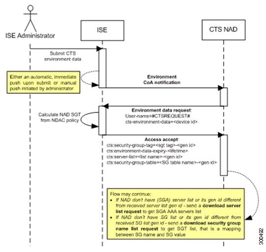
Environment CoA Notification Flow
The following figure depicts the Environment CoA notification flow.
-
Cisco ISE sends an environment CoA notification to the TrustSec network device.
-
In response to the environment data request, Cisco ISE returns:
The environment data of the device that sent the request—This includes the TrustSec device’s SGT (as inferred from the NDAC policy) and download environment TTL.
The name and generation ID of the TrustSec AAA server list.
The names and generation IDs of (potentially multiple) SGT tables—These tables list SGT name versus SGT value, and together these tables hold the full list of SGTs.
-
If the device does not hold a TrustSec AAA server list, or the generation ID is different from the generation ID that is received, the device sends another request to get the AAA server list content.
-
If the device does not hold an SGT table listed in the response, or the generation ID is different from the generation ID that is received, the device sends another request to get the content of that SGT table.
Environment CoA Triggers
- Trigger Environment CoA for Network Devices
- Trigger Environment CoA for Security Groups
- Trigger Environment CoA for TrustSec AAA Servers
- Trigger Environment CoA for NDAC Policy
Trigger Environment CoA for Network Devices
To trigger an Environment CoA for the Network devices, complete the following steps:
Trigger Environment CoA for Security Groups
To trigger an Environment CoA for the security groups, complete the following steps.
Trigger Environment CoA for TrustSec AAA Servers
To trigger an Environment CoA for the TrustSec AAA servers, complete the following steps.
Trigger Environment CoA for NDAC Policy
To trigger an Environment CoA for the NDAC Policies, complete the following steps.
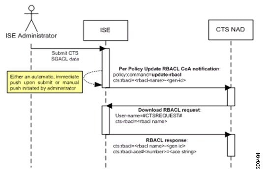
Update SGACL Content Flow
The following figure depicts the Update SGACL Content flow.
-
Cisco ISE sends an update SGACL named list CoA notification to a TrustSec network device. The notification contains the SGACL name and the generation ID.
-
The device may replay with an SGACL data request if both of the following terms are fulfilled:
If the SGACL is part of an egress cell that the device holds. The device holds a subset of the egress policy data, which are the cells related to the SGTs of its neighboring devices and endpoints (egress policy columns of selected destination SGTs).
The generation ID in the CoA notification is different from the generation ID that the device holds for this SGACL.
-
In response to the SGACL data request, Cisco ISE returns the content of the SGACL (the ACE).
Initiate an Update SGACL Named List CoA
To trigger an Update SGACL Named List CoA, complete the following steps:
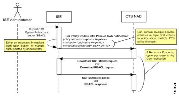
Policies Update CoA Notification Flow
The following figure depicts the Policies CoA Notification flow.
-
Cisco ISE sends an update policies CoA notification to a TrustSec network device. The notification may contain multiple SGACL names and their generation IDs, and multiple SGT values and their generation IDs.
-
The device may replay with multiple SGACL data requests and/or multiple SGT data.
-
In response to each SGACL data request or SGT data request, Cisco ISE returns the relevant data.
Update SGT Matrix CoA Flow
The following figure depicts the Update SGT Matrix CoA flow.
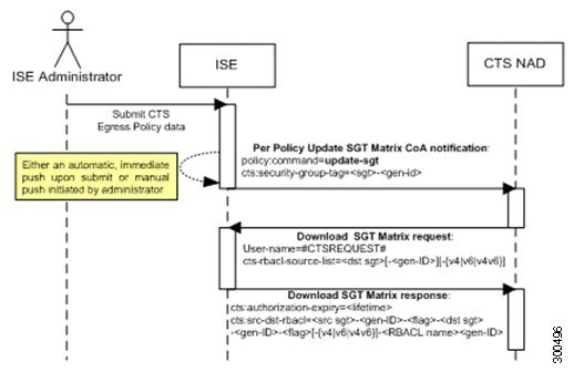
-
Cisco ISE sends an updated SGT matrix CoA notification to a TrustSec network device. The notification contains the SGT value and the generation ID.
-
The device may replay with an SGT data request if both the following terms are fulfilled:
If the SGT is the SGT of a neighboring device or endpoint, the device downloads and hold the cells related to SGTs of neighboring devices and endpoints (a destination SGT).
The generation ID in the CoA notification is different from the generation ID that the device holds for this SGT.
-
In response to the SGT data request, Cisco ISE returns the data of all egress cells, such as the source and destination SGTs, the status of the cell, and an ordered list of the SGACL names configured in that cell.
Initiate Update SGT Matrix CoA from Egress Policy
TrustSec CoA Summary
The following table summarizes the various scenarios that may require initiating a TrustSec CoA, the type of CoA used in each scenario, and the related UI pages.
Run Top N RBACL Drops by User Report
You can run the Top N RBACL Drops by User report to see the policy violations (based on packet drops) by specific users.
 Feedback