-
- Administration User Interface Reference
- Guest Access User Interface Reference
- Web Portals Customization Reference
- Policy User Interface Reference
- Operations User Interface Reference
- Network Access Flows
- Switch and Wireless LAN Controller Configuration Required to Support Cisco ISE Functions
- Supported Management Information Bases in Cisco ISE
- Cisco ISE Distributed Deployment
- Cisco ISE Deployment Terminology
- Personas in Distributed Cisco ISE Deployments
- Administration Node
- High Availability in Administration Nodes
- High-Availability Health Check Nodes
- Health Check of the Primary Administration Node
- Automatic Failover of the Secondary Administration Node
- Sample Scenarios when Automatic Failover is Avoided
- Fallback to the Original PAN
- Manual Promotion of the Secondary Administration Node
- Functionalities Affected by the PAN Auto-Failover Feature
- Policy Service Node
- Monitoring Node
- Cisco pxGrid Services
- Cisco pxGrid Live Logs
- ISE pxGrid Identity Mapping
- Configure Identity Mapping
- Filter Identity Mapping
- Active Directory Requirements to Support Identity Mapping
- Configure Active Directory for Identity Mapping
- Set the Windows Audit Policy
- Set Permissions When AD User in the Domain Admin Group
- Required Permissions When AD User Not in Domain Admin Group
- Permissions to Use DCOM on the Domain Controller
- Set Permissions for Access to WMI Root/CIMv2 Name Space
- Grant Access to the Security Event Log on the AD Domain Controller
Set Up Cisco ISE in a Distributed Environment
- Cisco ISE Distributed Deployment
- Cisco ISE Deployment Terminology
- Personas in Distributed Cisco ISE Deployments
- Administration Node
- Policy Service Node
- Monitoring Node
- Cisco pxGrid Services
- Cisco pxGrid Live Logs
- ISE pxGrid Identity Mapping
- Inline Posture Node
- Cisco ISE Distributed Deployment
- Configure a Cisco ISE Node
- Register an Inline Posture Node
- View Nodes in a Deployment
- Synchronize Primary and Secondary Cisco ISE Nodes
- Create a Policy Service Node Group
- Deploy Cisco pxGrid Services
- Change Node Personas and Services
- Manually Promote Secondary Administration Node To Primary
- Configure Primary Administration Node for Automatic Failover
- Configure Monitoring Nodes for Automatic Failover
- Remove a Node from Deployment
- Change the Hostname or IP Address of a Standalone Cisco ISE Node
- Replace the Cisco ISE Appliance Hardware
Cisco ISE Distributed Deployment
A deployment that has more than one Cisco ISE node is called a distributed deployment. To support failover and to improve performance, you can set up your deployment with multiple Cisco ISE nodes in a distributed fashion. In Cisco ISE distributed deployment, administration and monitoring activities are centralized, and processing is distributed across the Policy Service nodes. Depending on your performance needs, you can scale your deployment. Each Cisco ISE node in a deployment can assume any of the following personas: Administration, Policy Service, and Monitoring. The Inline Posture node cannot assume any other persona, due to its specialized nature. The Inline Posture node must be a dedicated node.
Cisco ISE Deployment Terminology
The following terms are commonly used when discussing Cisco ISE deployment scenarios:
-
Service—A service is a specific feature that a persona provides such as network access, profiler, posture, security group access, monitoring and troubleshooting, and so on.
-
Node—A node is an individual instance that runs the Cisco ISE software. Cisco ISE is available as an appliance and also as a software that can be run on VMware. Each instance, appliance or VMware that runs the Cisco ISE software is called a node.
-
Persona—The persona or personas of a node determine the services provided by a node. A Cisco ISE node can assume any of the following personas: Administration, Policy Service, Monitoring, pxGrid, and Inline Posture. The Inline Posture persona requires a dedicated Cisco ISE node. The menu options that are available through the Admin portal are dependent on the role and personas that an Cisco ISE node assumes.
-
Deployment Model—Determines if your deployment is distributed, standalone, or high availability in standalone, which is a basic two-node deployment.
Personas in Distributed Cisco ISE Deployments
A Cisco ISE node can assume the Administration, Policy Service, Monitoring, or Inline Posture personas.
A Cisco ISE node can provide various services based on the persona that it assumes. Each node in a deployment, with the exception of the Inline Posture node, can assume the Administration, Policy Service, and Monitoring personas. In a distributed deployment, you can have the following combination of nodes on your network:
-
Primary and secondary Administration nodes for high availability
-
A single or a pair of non-administration nodes for health check of Administration nodes for automatic failover
-
A pair of health check nodes or a single health check node for PAN automatic failover
You need to add Canonical Name (CNAME) record of the ISE hostname to the DNS. Ensure that you create CNAME RR along with the A record for each Cisco ISE node. If CNAME record is not created, it might result in the alarm ‘DNS Resolution failed for CNAME <hostname of the node>’.
Administration Node
A Cisco ISE node with the Administration persona allows you to perform all administrative operations on Cisco ISE. It handles all system-related configurations that are related to functionality such as authentication, authorization, auditing, and so on. In a distributed environment, you can have a maximum of two nodes running the administration persona. The administration persona can take on any one of the following roles: Standalone, Primary, or Secondary.
- High Availability in Administration Nodes
- High-Availability Health Check Nodes
- Health Check of the Primary Administration Node
- Automatic Failover of the Secondary Administration Node
- Sample Scenarios when Automatic Failover is Avoided
- Fallback to the Original PAN
- Manual Promotion of the Secondary Administration Node
- Functionalities Affected by the PAN Auto-Failover Feature
High Availability in Administration Nodes
In a high-availability configuration, the PAN is in the active state to which all configuration changes are made. The Secondary Administration Node is in the standby state, and will receive all configuration updates from the PAN. Therefore, it will always have a complete copy of the configuration from the PAN.
If the PAN goes down, you must log in to the user interface of the Secondary Administration Node and manually promote the Secondary Administration Node. There is no automatic failover for the Administration persona.
When the PAN is down, sponsors cannot create new guest accounts. During this time, guest and sponsor portals will provide read-only access to already created guests and sponsors, respectively. Also, a sponsor who has never logged in to the sponsor portal before the PAN goes offline, will not be able to log in to the sponsor portal until a Secondary Administration Node is promoted or the PAN becomes available.
At least one node in your distributed setup should assume the Administration persona.
The following table lists a set of features and specifies whether they are available or not when the PAN goes down.
|
Feature |
Available When the PAN Goes Down(Yes/No) |
|---|---|
|
Existing internal user RADIUS authentication |
Yes |
|
Existing or New AD user RADIUS authentication |
Yes |
|
Existing endpoint with no profile change |
Yes |
|
Existing endpoint with profile change |
Yes |
|
New endpoint learned through profiling |
Yes |
|
Existing guest – LWA |
Yes |
|
Existing guest – CWA |
Yes |
|
Guest change password |
No (Guest must log in with old password) |
|
Guest – AUP |
Yes |
|
Guest – Max Failed Login Enforcement |
No |
|
New Guest (Sponsored or Self-registered) |
No |
|
Posture |
Yes |
|
New Device Registration |
No |
|
Existing Registered Devices |
Yes |
|
pxGrid Service |
No |
In a high availability configuration, the PAN is in the active state to which all configuration changes are made. The Secondary Administration Node is in the standby state, and will receive all configuration updates from the PAN. Therefore, it will always have a complete copy of the configuration from the PAN.
Cisco ISE supports automatic failover for the Administration persona. If the PAN goes down, an automatic promotion of the Secondary Administration Node is initiated. For this, a non-administration secondary node is designated as the health check node for each of the administration nodes. The health check node checks the health of PAN in the configured interval called the 'Polling Interval'. If the health check response received for the PAN health is down or unreachable, the health check node initiates the promotion of the Secondary Administration Node to take over the primary role after waiting for configured threshold value of 'Count of failures before failover'.
To enable the auto-failover feature, at least two nodes in your distributed setup should assume the Administration persona and one node should assume the non-Administration persona.
The following table lists the features that are affected when the PAN goes down and the Secondary Administration Node is yet to take over.
|
Features |
Available When PAN is Down (Yes/No) |
|---|---|
|
Existing internal user RADIUS authentication |
Yes |
|
Existing or New AD user RADIUS authentication |
Yes |
|
Existing endpoint with no profile change |
Yes |
|
Existing endpoint with profile change |
No |
|
New endpoint learned through profiling |
No |
|
Existing guest – LWA |
Yes |
|
Existing guest – CWA |
Yes (apart from flows enabled for device registration, such as Hotspot, BYOD, and CWA with automatic device registration) |
|
Guest change password |
No |
|
Guest – AUP |
No |
|
Guest – Max Failed Login Enforcement |
No |
|
New Guest (Sponsored or Self-registered) |
No |
|
Posture |
Yes |
|
BYOD with Internal CA |
No |
|
Existing Registered Devices |
Yes |
|
MDM On-boarding |
No |
|
pxGrid Service |
No |
For certificate provisioning with the internal certificate authority, you have to import the root certificate of the original PAN and its key in to the new primary node, after promotion. Certificate provisioning will not work post auto-failover from PSN nodes that are newly added, that is, added after the promotion of the secondary node to PAN.
High-Availability Health Check Nodes
Health check node for PAN is called active health check node whereas health check node for Secondary Administration Node is called passive health check node. Active health check node is responsible for checking status of PAN and managing the automatic failover of Administration nodes. It is recommended to have two non-administration ISE nodes designated as the health check nodes, one each for the primary and Secondary Administration Nodes. You can also designate a single non-administration ISE node as the health check node for both the PAN and the Secondary Administration Node. In case a single health check node is checking the health of both the PAN and the Secondary Administration Node, it assumes both the active and passive roles.
A health check node is a non-administration node and can be a Policy Service, Monitoring, or pxGrid node, or a combination of these. It is recommended that PSN nodes that are in the same data center as the Administration nodes, are designated as high-availability health check nodes. However, in a small or a centralized deployment where the two Administration nodes are in the same location (LAN or data center), any node (PSN/pxGrid/MnT) not having the Administration persona can be used as high-availability health check node.
- Health Probe by Health Check Nodes
- Startup of Health Check Node
- Shutdown of Health Check Node
- Restart of Health Check Node
Health Probe by Health Check Nodes
The health check node for the PAN reaches out for its health status, for the configured polling intervals. If the health status of the PAN is down or unreachable for the configured 'Number of failure polls before failover' value, the primary health check node notifies the Secondary Administration Node to take over as the PAN of the deployment.
The health check node for automatic failover is the single point of failure. If the health check node for the PAN itself goes down, high-availability failover will not happen.
Startup of Health Check Node
The health check node for the Secondary Administration Node is a passive monitor. It does not take any action until the Secondary Administration Node has been promoted as the PAN. When the Secondary Administration Node takes over the primary role, its associated health check node takes the active role for managing automatic failover of Administration nodes. The health check node of the previous PAN becomes the health check node for the Secondary Administration Node now and would monitor it passively.
Shutdown of Health Check Node
When a node is removed from the health check role or auto-failover configuration is disabled, the health check service is stopped on that node. When the auto-failover configuration is enabled on the designated high-availability health check node, the node starts checking health of Administration nodes again. Designating or removing the high-availability health check role on a node does not involve any application restart on that node; only the health check activities are started or stopped.
Restart of Health Check Node
If the high-availability health check node is restarted, it ignores the previous downtimes of PAN and starts checking the health status afresh.
Health Check of the Primary Administration Node
The active health check node checks the health status of the Primary Administration Node (PAN) at a configured polling interval. It sends a request to the PAN, and if the response that it receives satisfies the specified configuration, then the health check node considers the PAN to be in good health. Otherwise, the health check node considers the PAN to be in bad health. If the health of the PAN is bad continuously for more than the configured 'Number of Failure Polls before Failover' value, health check node initiates failover to the Secondary Administration Node.
If at any time during the health check, health status is found to be good after being reported as bad previously within the 'Number of Failure Polls before Failover' value, health check node marks the PAN status as good and resets the health check cycle.
Response from health check of the PAN is validated against the configuration values available on it's health check node. If the response does not match it would raise an alarm. However, a promotion request will be made to the Secondary Administration Node.
For example, assume that the health check node (N1) goes out-of-sync and some other node (N2) is made the health check node of the PAN. In such a case, once the PAN goes down, there is no way for N1 to know that there is another node (N2) checking the same PAN. Later, if N2 too goes down or out of network, an actual failover would be required. The Secondary Administration Node, however, retains the right to reject the promotion request. So, once the Secondary Administration Node has been promoted to the primary role, further promotion request (from the node checking node N2) would be rejected with an error. Even if the high-availability health check node for PAN is out of sync, it continues to check the health of PAN. If the health check response is valid for failover (that is, response says that the correct PAN is checked by the correct health check node and health check node has the correct Secondary Administration Node information), it would also attempt to failover to the Secondary Administration Node when the PAN meets the failover criteria.
Automatic Failover of the Secondary Administration Node
If all the validations pass, secondary Administration node promotes itself to the primary role.
The following are some sample (but not limited to) scenarios where automatic failover of the secondary Administration node would be attempted.
-
Health of PAN is consistently not good for the 'Number of failure polls before failover' value during the polling period.
-
Cisco ISE services on the PAN is manually stopped and remains so for the configured 'Number of Failure Polls before Failover' value.
-
PAN is shut down using soft halt or reboot option and remains shut for the configured 'Number of Failure Polls before Failover' value.
-
PAN goes down abruptly (power down) and remains down for the configured 'Number of Failure Polls before Failover' value.
-
Network interface of PAN is down (network port shut or network service down) or it is not reachable by the health check node for any other reason and remains so for the configured 'Number of Failure Polls before Failover' value.
Sample Scenarios when Automatic Failover is Avoided
The following are some sample scenarios that depict cases where automatic failover by the health check node would be avoided or promotion request to the secondary node would be rejected.
-
Node receiving the promotion request is not the secondary node.
-
Promotion request does not have the correct PAN information.
-
Promotion request is received from an incorrect health check node.
-
Promotion request is received but the PAN is up and in good health.
-
Node receiving the promotion request goes out-of-sync.
Fallback to the Original PAN
Cisco ISE does not support fallback to original PAN. This means that after the automatic failover to the Secondary Administration Node is initiated, if the original PAN is brought back into the network, the original primary node would continue to have the secondary role and would not be promoted back to the primary role.
Manual Promotion of the Secondary Administration Node
Cisco ISE supports both automatic and manual promotion of secondary Administration node to the primary role. When auto-failover is enabled, you can still perform manual promotion of the secondary Administration node. Promotion of the secondary Administration node to primary role is fairly independent and is not affected whether the promotion is performed manually or automatically.
Functionalities Affected by the PAN Auto-Failover Feature
The following table lists the functionalities that are blocked or require additional configuration changes if PAN auto-failover configuration is enabled in your deployment.
|
Functionality |
Affect Details |
|---|---|
|
Operations that are Blocked |
|
|
Upgrade |
Upgrade via the CLI is blocked. The PAN auto-failover feature will be available for configuration after you upgrade from a previous version of Cisco ISE to release 1.4. By default, this feature is disabled. You must have at least two Administrative nodes and one non-Administrative node in your deployment to enable PAN auto-failover. |
|
Restore of Backup |
Restore via the CLI and user interface will be blocked. If PAN auto-failover configuration was enabled prior to restore, you must reconfigure it after a successful restore. |
|
Change Node Persona |
Change of the following node personas via the user interface will be blocked: |
|
Other CLI Operations |
The following admin operations via the CLI will be blocked: |
|
Other Administration Portal Operations |
The following admin operations via the user interface will be blocked: |
|
Operations that Require PAN Auto-Failover to be Disabled |
|
|
CLI Operations |
The following admin operations via the CLI will display a warning message if PAN auto-failover configuration is enabled. These operations may trigger auto-failover if service/system is not restarted within failover window. Hence, while performing the below operations it is recommended to disable PAN auto-failover configuration: |
Policy Service Node
A Cisco ISE node with the Policy Service persona provides network access, posture, guest access, client provisioning, and profiling services. This persona evaluates the policies and makes all the decisions. You can have more than one node assume this persona. Typically, there would be more than one Policy Service node in a distributed deployment. All Policy Service nodes that reside in the same high-speed Local Area Network (LAN) or behind a load balancer can be grouped together to form a node group. If one of the nodes in a node group fails, the other nodes detect the failure and reset any URL-redirected sessions.
At least one node in your distributed setup should assume the Policy Service persona.
- High Availability in Policy Service Nodes
- Load Balancer To Distribute Requests Evenly Among PSNs
- Session Failover in Policy Service Nodes
- Number of Nodes in a Policy Service Node Group
High Availability in Policy Service Nodes
To detect node failure and to reset all URL-redirected sessions on the failed node, two or more Policy Service nodes can be placed in the same node group. When a node that belongs to a node group fails, another node in the same node group issues a Change of Authorization (CoA) for all URL-redirected sessions on the failed node.
All the nodes within the same node group should be configured on the network access device (NAD) as RADIUS clients and authorized for CoA, because any one of them can issue a CoA request for the sessions that are established through any node in the node group. If you are not using a load balancer, the nodes in a node group should be the same as, or a subset of, the RADIUS servers and clients configured on the NAD. These nodes would also be configured as RADIUS servers.
While a single NAD can be configured with many ISE nodes as RADIUS servers and dynamic-authorization clients, it is not necessary for all the nodes to be in the same node group.
The members of a node group should be connected to each other using high-speed LAN connection such as Gigabit Ethernet. The node group members need not be L2 adjacent, but L2 adjacency is highly recommended to ensure sufficient bandwidth and reachability. See Create a Policy Service Node Group section for more details.
Load Balancer To Distribute Requests Evenly Among PSNs
When you have multiple Policy Service nodes in the deployment, you can use a load balancer to distribute the requests evenly. The load balancer distributes the requests to the functional nodes behind it. Refer to the Cisco and F5 Deployment Guide: ISE Load Balancing using BIG-IP for information on and best practices about deploying PSNs behind a load balancer.
Session Failover in Policy Service Nodes
When a Policy Service node that has active URL-redirected sessions fails, the endpoints are stuck in an intermediate state. Even if the redirect endpoint detects that the Policy Service node that it has been communicating with has failed, it cannot re-initiate authorization.
If the Policy Service nodes are part of a node group, the nodes within a node group exchange heartbeat messages to detect node failures. If a node fails, one of its peers from the node group learns about the active URL-redirected sessions on the failed node and issues a CoA to disconnect those sessions.
As a result, the sessions are handled by another Policy Service node that is available in the same node group. The session failover does not automatically move the sessions over from a Policy Service node that has gone down to one that is available, but issues a CoA to achieve that.
The Policy Service nodes in a distributed deployment do not share their Machine Access Restriction (MAR) cache with each other. If you have enabled the MAR feature in Cisco ISE and the client machine is authenticated by a Policy Service node that fails, then another Policy Service node in the deployment handles the user authentication. However, the user authentication fails because the second Policy Service node does not have the host authentication information in its MAR cache.
Number of Nodes in a Policy Service Node Group
The number of nodes that you can have in a node group depends on your deployment requirements. Node groups ensure that node failures are detected and that a peer issues a CoA for sessions that are authorized, but not yet postured. The size of the node group does not have to be very large.
If the size of the node group increases, the number of messages and heartbeats that are exchanged between nodes increases significantly. As a result, traffic also increases. Having fewer nodes in a node group helps reduce the traffic and at the same time provides sufficient redundancy to detect Policy Service node failures.
You can have a maximum of 10 Policy Service nodes in a node group cluster.
Monitoring Node
A Cisco ISE node with the Monitoring persona functions as the log collector and stores log messages from all the administration and Policy Service nodes in your network. This persona provides advanced monitoring and troubleshooting tools that you can use to effectively manage your network and resources. A node with this persona aggregates and correlates the data that it collects to provide you with meaningful information in the form of reports.
Cisco ISE allows you to have a maximum of two nodes with this persona that can take on primary or secondary roles for high availability. Both the primary and secondary Monitoring nodes collect log messages. In case the primary Monitoring node goes down, the secondary Monitoring node automatically becomes the primary Monitoring node.
At least one node in your distributed setup should assume the Monitoring persona. We recommend that you not have the Monitoring and Policy Service personas enabled on the same Cisco ISE node. We recommend that the node be dedicated solely to monitoring for optimum performance.
You can access the Monitoring menu from the PAN and the Primary Monitoring Node in your deployment.
Automatic Failover in Monitoring Nodes
The term automatic failover is used because high availability is not supported on Monitoring nodes in the true sense. For Monitoring nodes, operation audit data is duplicated by the Policy Service node(s), which then sends copies to both the primary and secondary Monitoring nodes.
Automatic Failover Process
When a primary Monitoring node goes down, the secondary Monitoring node takes over all monitoring and troubleshooting information. The secondary node provides read-only capabilities.
To convert the existing secondary node to an active primary node, the administrator must first manually promote the secondary node to a primary role. If the primary node comes back up after the secondary node has been promoted, it assumes the secondary role. If the secondary node was not promoted, the primary Monitoring node will resume its role after it comes back up.
 Caution | When the primary node comes back up after a failover, obtain a backup and restore the data to update the primary node. |
Guidelines for Setting Up an Active-Standby Pair of Monitoring Nodes
You can specify two Monitoring nodes on an ISE network and create an active-standby pair. When you register a secondary Monitoring node, we recommend that you back up the primary Monitoring node and then restore the data to the new secondary Monitoring node. This ensures that the history of the primary Monitoring node is in sync with the new secondary node as new changes are replicated. Once the active-standby pair is defined, the following rules apply:
-
All changes must be made on the primary Monitoring node. The secondary node is read-only.
-
Changes made to the primary node are automatically replicated on the secondary node.
-
Both the primary and secondary nodes are listed as log collectors to which all other nodes send logs.
-
The Cisco ISE dashboard is the main entry point for monitoring and troubleshooting. Monitoring information is displayed on the dashboard from the primary Monitoring node. If the primary node goes down, the information is served from the secondary node.
-
Backing up and purging monitoring data is not part of a standard Cisco ISE node backup process. You must configure repositories for backup and data purging on both the primary and secondary Monitoring nodes, and use the same repositories for each.
Monitoring Node Failover Scenarios
The following scenarios apply to the active-standby or single node configurations corresponding to the monitoring nodes:
-
In an active-standby configuration of the monitoring nodes, the Primary Administration Node (PAN) always points to the active monitoring node to collect the monitoring data. After the active monitoring node fails, the PAN points to the standby monitoring node. The failover from the active monitoring node to the standby monitoring node happens after it is down for more than 5 minutes.
However, after the active node fails, the standby node does not become the active node. In case the active node comes up, the Administration node starts collecting the monitoring data again from the resumed active node.
-
During the time that the active monitoring node is down, if you want to promote the standby monitoring node to active status, you must de-register the existing active monitoring node. When you de-register the existing active monitoring node, the standby node becomes the active monitoring node and the PAN automatically starts pointing to the newly promoted active node.
-
In an active-standby pair, if you choose to de-register the standby monitoring node from the deployment or if the standby monitoring node goes down, the existing active monitoring node still retains the active node status. The PAN points to the existing active node for data collection.
-
If there is only one monitoring node in the ISE deployment, then that node acts as the active monitoring node that provides monitoring data to the PAN. However, when you register a new monitoring node and make it the active node in the deployment, the existing active monitoring node automatically becomes the standby node. The PAN begins to point to the newly registered active monitoring node for collecting monitoring data.
Cisco pxGrid Services
You can use Cisco pxGrid to share the context-sensitive information from Cisco ISE session directory with other network systems such as ISE Eco system partner systems and other Cisco platforms. The pxGrid framework can also be used to exchange policy and configuration data between nodes like sharing tags and policy objects between Cisco ISE and third party vendors, and for other information exchanges. pxGrid also allows 3rd party systems to invoke adaptive network control actions (EPS) to quarantine users/devices in response to a network or security event. The TrustSec information like tag definition, value, and description can be passed from Cisco ISE via TrustSec topic to other networks. The endpoint profiles with Fully Qualified Names (FQNs) can be passed from Cisco ISE to other networks through a endpoint profile meta topic. Cisco pxGrid also supports bulk download of tags and endpoint profiles.
In a high-availability configuration, Cisco pxGrid servers replicate information between the nodes through the PAN. When the PAN goes down, pxGrid server stops handling the client registration and subscription. You need to manually promote the PAN for the pxGrid server to become active.
pxGrid Client and Capability Management
Clients connected to Cisco ISE need to register to use the pxGrid services. pxGrid clients should adopt the pxGrid Client Library available from Cisco through the pxGrid SDK to become the clients. Cisco pxGrid clients need an approved account to participate in pxGrid services. Cisco ISE supports both auto and manual approvals. A client can log in to pxGrid using a unique name and certificate-based mutual authentication. Similar to the AAA setting on a switch, clients can connect to either a configured pxGrid server host-name or an IP Address.
Capabilities are information topics or channels created on pxGrid for clients to publish and subscribe. In Cisco ISE, only capabilities such as Identity, adaptive network control, and SGA are supported. You can enable or disable capabilities. If disabled, the client is unsubscribed. Capability information is available from the publisher through publish, directed query, or bulk download query.
Enable pxGrid Clients
-
Enable the pxGrid persona on at least one node to view the requests from the Cisco pxGrid clients.
-
Enable Identity Mapping. For more information, see Configure Identity Mapping.
Cisco pxGrid Live Logs
The Live Logs page displays all the pxGrid management events. Event info includes the client and capability names along with the event type and timestamp.
Navigate to to view the list of events. You can also clear the logs and resynchronize or refresh the list.
ISE pxGrid Identity Mapping
Identity Mapping enables you to monitor users that are authenticated by a Domain Controller (DC) and not by Cisco ISE. In networks where Cisco ISE does not actively authenticate users for network access, it is possible to use Identity Mapping to collect user authentication information from the active directory (AD) Domain Controller. The Identity Mapping connects to Windows system using the MS WMI interface and queries logs from the Windows event messaging. Once a user logs into the network and is authenticated with an Active Directory, the Domain Controller generates an event log that includes the user name and IP address allocated for the user.
Identity mapping can also be activated even if Cisco ISE plays an active role for authentication. In such cases, the same session may be identified twice. The operational data has a session attribute that indicates the source. You can go to Operations > Authentications and click Show Live Sessions to check the Session Source.
The Identity Mapping component retrieves the user logins from the Domain Controller and imports them into the Cisco ISE session directory. So users authenticated with Active Directory (AD) are shown in the Cisco ISE live sessions view, and can be queried from the session directory using Cisco pxGrid interface by third-party applications. The known information is the user name, IP address, and the AD DC host name and the AD DC NetBios name.
The Cisco ISE plays only a passive role and does not perform the authentication. When Identity Mapping is active, Cisco ISE collects the login information from the AD and includes the data into the session directory.
Key Features
- Identity Mapping is
configured from the Cisco ISE administration console. The configuration
includes the following settings:
- Definition of all the DCs from which Identity Mapping is to collect user authentication information. This also includes import and export of the DC list using *.csv files
- DC connection characteristics such as authentication security protocol (NTLMv1 or NTLMv2) and user session aging time
- Connection testing, to verify the DC is set correctly to initialize valid connection with Identity Mapping
- Identity Mapping report. This report provides information about the Identity Mapping component for troubleshooting
- Identity Mapping debug logs
- Cisco ISE session directory maintains the collected user information, so that customers can view it from the Live Sessions and query it from the pxGrid interface
- Using the CLI command show application status provides the health status of nodes that use Identity Mapping
- Supports High Availability
Configuring Identity Mapping
ID Mapping requires configuration in ISE, and the Active Directory Domain Server must have the right patches and configuration. For information about configuring the Active Directory domain controller for ISE, see Active Directory Requirements to Support Identity Mapping
- Configure Identity Mapping
- Filter Identity Mapping
- Active Directory Requirements to Support Identity Mapping
Configure Identity Mapping
ISE must be able to establish a connection with an AD Domain Controller (DC).
Enable pxGrid services to configure Identity Mapping. Choose to enable pxGrid services.
To add a new Domain Controller (DC) for Identity Mapping, you need the login credentials of that DC.
Make sure the Domain Controller is properly configured for ISE Identity Mapping, as described in Active Directory Requirements to Support Identity Mapping.
Filter Identity Mapping
Active Directory Requirements to Support Identity Mapping
Identity Mapping uses Active Directory login audit events generated by the Active Directory domain controller to gather user login information. The Active Directory server must be configured properly so the ISE user can connect and fetch the user logins information. The following sections show how configure the Active Directory domain controller to support ISE Identity Mapping .
- Configure Active Directory for Identity Mapping
- Set the Windows Audit Policy
- Set Permissions When AD User in the Domain Admin Group
- Required Permissions When AD User Not in Domain Admin Group
- Permissions to Use DCOM on the Domain Controller
- Set Permissions for Access to WMI Root/CIMv2 Name Space
- Grant Access to the Security Event Log on the AD Domain Controller
Configure Active Directory for Identity Mapping
ISE Identity Mapping uses Active Directory login audit events generated by the Active Directory domain controller to gather user login information. ISE connects to Active Directory and fetches the user login information.
The following steps should be performed from the Active Directory domain controller:
| Step 1 | Make sure
relevant Microsoft patches are installed on the Active Directory domain
controllers.
| |||||||||||||||||||||
| Step 2 | Make sure the
Active Directory logs the user login events in the Windows Security Log.
Verify that the settings of the “Audit Policy” (part of the “Group Policy Management” settings) allows successful logons to generate the necessary events in the Windows Security Log (this is the default Windows setting, but you must explicitly ensure that this setting is correct). See Setting the Windows Audit Policy. | |||||||||||||||||||||
| Step 3 | You must have an Active Directory user with sufficient permissions for ISE to connect to the Active Directory. The following instructions show how to define permissions either for admin domain group user or none admin domain group user: | |||||||||||||||||||||
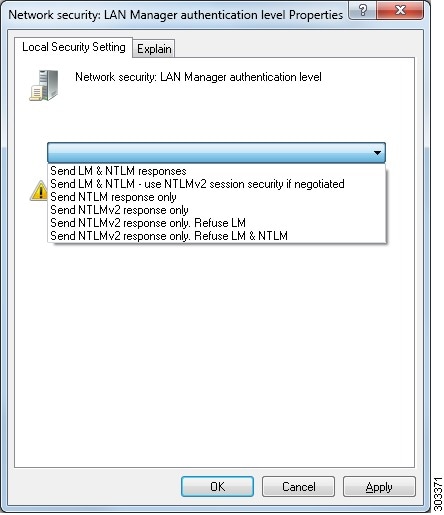
| Step 4 | The Active
Directory user used by ISE can be authenticated either by NT Lan Manager (NTLM)
v1 or v2. You need to verify that the Active Directory NTLM settings are
aligned with ISE NTLM settings to ensure successful authenticated connection
between ISE and the Active Directory Domain Controller. The following table
shows all Microsoft NTLM options, and which ISE NTLM actions are supported. If
ISE is set to NTLMv2, all six options described in are supported. If ISE is set
to support NTLMv1, only the first five options are supported.
 | |||||||||||||||||||||
| Step 5 | Make sure that you have created a firewall rule to allow traffic to dllhost.exe on Active Directory domain controllers.
You can either turn the firewall off, or allow access on a specific IP (ISE IP address) to the following ports:
Higher ports are assigned dynamically or you can configure them manually. We recommend that you add %SystemRoot%\System32\dllhost.exe as a target. This program manages ports dynamically. All firewall rules can be assigned to specific IP (ISE IP). |
Set the Windows Audit Policy
Ensure that the Audit Policy (part of the Group Policy Management settings) allows successful logons. This is required to generate the necessary events in the Windows Security Log of the AD domain controller machine. This is the default Windows setting, but you must verify that this setting is correct.
| Step 1 | Choose . |
| Step 2 | Navigate under Domains to the relevant domain and expand the navigation tree. |
| Step 3 | Choose
Default
Domain Controller Policy, right click and choose
Edit.
The Group Policy Management Editor appears. |
| Step 4 | Choose
.
|
| Step 5 | If any Audit Policy item settings have been changed, you should then run gpupdate /force to force the new settings to take effect. |
Set Permissions When AD User in the Domain Admin Group
For Windows 2008 R2,Windows 2012, and Windows 2012 R2, the Domain Admin group does not have full control on certain registry keys in the Windows operating system by default. The Active Directory admin must give the Active Directory user Full Control permissions on the following registry keys:
-
HKEY_CLASSES_ROOT\CLSID\{76A64158-CB41-11D1-8B02-00600806D9B6}
-
HKLM\Software\Classes\Wow6432Node\CLSID\{76A64158-CB41-11D1-8B02-00600806D9B6}
No registry changes are required for the following Active Directory versions:
To grant full control, the Active Directory admin must first take ownership of the key, as shown below.
Required Permissions When AD User Not in Domain Admin Group
For Windows 2012 R2, give the Active Directory user Full Control permissions on the following registry keys:
-
HKEY_CLASSES_ROOT\CLSID\{76A64158-CB41-11D1-8B02-00600806D9B6}
-
HKLM\Software\Classes\Wow6432Node\CLSID\{76A64158-CB41-11D1-8B02-00600806D9B6}
The following permissions also are required when an Active Directory user is not in the Domain Admin group, but is in the Domain Users group:
-
Add Registry Keys to Allow ISE to Connect to the Domain Controller (see below)
- Permissions to Use DCOM on the Domain Controller
- Set Permissions for Access to WMI Root/CIMv2 Name Space
- Grant Access to the Security Event Log on the AD Domain Controller
These permissions are only required for the following Active Directory versions:
Add Registry Keys to Allow ISE to Connect to the Domain Controller
You must manually add some registry keys to the domain controller to allow ISE to connect as a Domain User, and retrieve login authentication events. An agent is not required on the domain controllers or on any machine in the domain.
The following registry script shows the keys to add. You can copy and paste this into a text file, save the file with a .reg extension, and double click the file to make the registry changes. To add registry keys, the user must be an owner of the root key.
Windows Registry Editor Version 5.00

[HKEY_CLASSES_ROOT\CLSID\{76A64158-CB41-11D1-8B02-00600806D9B6}]
"AppID"="{76A64158-CB41-11D1-8B02-00600806D9B6}"

[HKEY_CLASSES_ROOT\AppID\{76A64158-CB41-11D1-8B02-00600806D9B6}]
"DllSurrogate"="  "

[HKEY_CLASSES_ROOT\Wow6432Node\AppID\{76A64158-CB41-11D1-8B02-00600806D9B6}]
"DllSurrogate"="  "
Make sure that you include two spaces in the value of the key DllSurrogate.
Keep the empty lines as shown in the script above, including an empty line at the end of the file.
Permissions to Use DCOM on the Domain Controller
The Active Directory user used for ISE ID Mapping must have permissions to use DCOM (remote COM) on the Domain Controller. You can configure permissions with the dcomcnfg command line tool.
| Step 1 | Run the dcomcnfg tool from the command line. |
| Step 2 | Expand Component Services. |
| Step 3 | Expand . |
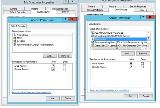
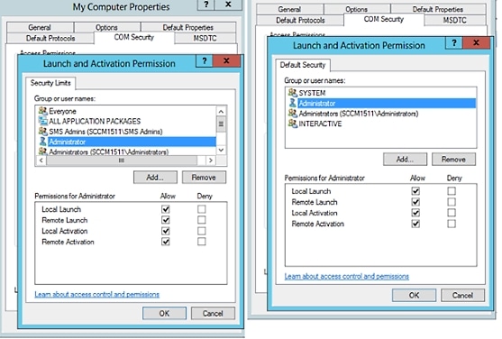
| Step 4 | Select Action from the menu bar, click properties, and click COM Security. |
| Step 5 | Make sure that the account that ISE will use for both Access and Launch has Allow permissions. That Active Directory user should be added to all the four options (Edit Limits and Edit Default for both Access Permissions and Launch and Activation Permissions). |
| Step 6 | Allow all Local
and Remote access for both Access Permissions and Launch and Activation
Permissions.
  |
Set Permissions for Access to WMI Root/CIMv2 Name Space
By default, Active Directory users do not have permissions for the Execute Methods and Remote Enable. You can grant access using the wmimgmt.msc MMC console.
| Step 1 | Click Start > Run and type wmimgmt.msc. |
| Step 2 | Right-click WMI Control and click Properties. |
| Step 3 | Under the Security tab, expand Root and choose CIMV2. |
| Step 4 | Click Security. |
| Step 5 | Add the Active
Directory user, and configure the required permissions as shown below.
 |
Grant Access to the Security Event Log on the AD Domain Controller
On Windows 2008 and later, you can grant access to the AD Domain controller logs by adding the ISE ID Mapping user to a group called Event Log Readers.
On all older versions of Windows, you must edit a registry key, as shown below.
| Step 1 | To delegate access to the Security event logs, find the SID for the account . |
| Step 2 | Use the
following command from the command line, also shown in the diagram below, to
list all the SID accounts.
wmic useraccount get name,sid You can also use the following command for a specific username and domain: wmic useraccount where name=“cdaUser” get domain,name,sid  |
| Step 3 | Find the SID,
open the Registry Editor, and browse to the following location:
HKEY_LOCAL_MACHINE/SYSTEM/CurrentControlSet/Services/Eventlog |
| Step 4 | Click on
Security, and double click
CustomSD. See Figure 2-7
For example, to allow read access to the cda_agent account (SID - S-1-5-21-1742827456-3351963980-3809373604-1107), enter (A;;0x1;;;S-1-5-21-1742827456-3351963980-3809373604-1107). 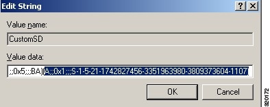 |
| Step 5 | Restart the WMI
service on the Domain Controller. You can restart the WMI services in the
following two ways:
|
Inline Posture Node
An Inline Posture node is a gatekeeping node that is positioned behind network access devices such as Wireless LAN Controllers (WLC) and VPN concentrators on the network. The Inline Posture node enforces access policies after a user has been authenticated and granted access, and handles change of authorization (CoA) requests that a WLC or VPN are unable to accommodate. Cisco ISE allows you to have two Inline Posture nodes that can take on primary or secondary roles for high availability.
The Inline Posture node must be a dedicated node. It must be dedicated solely for inline posture service, and cannot operate concurrently with other Cisco ISE services. Likewise, due to the specialized nature of its service, an Inline Posture node cannot assume any persona. For example, it cannot act as an Administration node that offers administration service, or a Policy Service node that offers network access, posture, profile, and guest services, or a Monitoring node that offers monitoring and troubleshooting services for a Cisco ISE network.
The Inline Posture persona is not supported on the Cisco ISE 3495 platform. Ensure that you install the Inline Posture persona on any one of the following supported platforms: Cisco ISE 3315, Cisco ISE 3355, Cisco ISE 3395, or Cisco ISE 3415.
You cannot access the web-based user interface of the Inline Posture nodes. You can configure them only from the PAN.
Inline Posture Node Installation
You must download the Inline Posture ISO (IPN ISO) image from Cisco.com and install it on any of the supported platforms. You must then configure certificates through the Command Line Interface (CLI). You can then register this node from the Admin portal.
 Note | There is no separate Inline Posture ISO image for Release 1.31.4. Use the 1.2 IPN ISO image to install and set up an inline posture node. |
After you install and set up the Inline Posture application, you must configure certificates before you can register the Inline Posture nodes. See the Cisco Identity Services Engine Hardware Installation Guide for more information.
Cisco ISE Distributed Deployment
A deployment that has more than one Cisco ISE node is called a distributed deployment. To support failover and to improve performance, you can set up your deployment with multiple Cisco ISE nodes in a distributed fashion. In Cisco ISE distributed deployment, administration and monitoring activities are centralized, and processing is distributed across the Policy Service nodes. Depending on your performance needs, you can scale your deployment. Each Cisco ISE node in a deployment can assume any of the following personas: Administration, Policy Service, and Monitoring. The Inline Posture node cannot assume any other persona, due to its specialized nature. The Inline Posture node must be a dedicated node.
- Cisco ISE Deployment Setup
- Data Replication from Primary to Secondary ISE Nodes
- Cisco ISE Node Deregistration
- Automatic Restart of the Cisco ISE Application Server
- Guidelines for Setting Up a Distributed Deployment
- Menu Options Available on Primary and Secondary Nodes
Cisco ISE Deployment Setup
After you install Cisco ISE on all your nodes, as described in the Cisco Identity Services Engine Hardware Installation Guide, the nodes come up in a standalone state. You must then define one node as your Primary Administration Node (PAN). While defining your PAN, you must enable the Administration and Monitoring personas on that node. You can optionally enable the Policy Service persona on the PAN. After you complete the task of defining personas on the PAN, you can then register other secondary nodes to the PAN and define personas for the secondary nodes.
All Cisco ISE system and functionality-related configurations should be done only on the PAN. The configuration changes that you perform on the PAN are replicated to all the secondary nodes in your deployment.
There must be at least one Monitoring node in a distributed deployment. At the time of configuring your PAN, you must enable the Monitoring persona. After you register a Monitoring node in your deployment, you can edit the PAN and disable the Monitoring persona, if required.
Data Replication from Primary to Secondary ISE Nodes
When you register an Cisco ISE node as a secondary node, Cisco ISE immediately creates a data replication channel from the primary to the secondary node and begins the process of replication. Replication is the process of sharing Cisco ISE configuration data from the primary to the secondary nodes. Replication ensures consistency among the configuration data present in all Cisco ISE nodes that are part of your deployment.
A full replication typically occurs when you first register an ISE node as a secondary node. Incremental replication occurs after a full replication and ensures that any new changes such as additions, modifications, or deletions to the configuration data in the PAN are reflected in the secondary nodes. The process of replication ensures that all Cisco ISE nodes in a deployment are in sync. You can view the status of replication in the Node Status column from the deployment pages of the Cisco ISE Admin portal. When you register a Cisco ISE node as a secondary node or perform a manual synchronization with the PAN, the node status shows an orange icon indicating that the requested action is in progress. Once it is complete, the node status turns green indicating that the secondary node is synchronized with the PAN. After the node status turns green, it takes about five minutes for the Cisco ISE application server to restart and run to complete the secondary ISE node configuration.
Cisco ISE Node Deregistration
To remove a node from a deployment, you must deregister it. When you deregister a secondary node from the PAN, the status of the deregistered node changes to standalone and the connection between the primary and the secondary node will be lost. Replication updates are no longer sent to the deregistered standalone node.
Note |
Automatic Restart of the Cisco ISE Application Server
The application server in an Cisco ISE node restarts which causes a delay when you make any of the following changes:
Change a primary node to Standalone (if no other nodes are registered with it; Primary to Standalone)
Change the personas (when you assign or remove the Policy Service or Monitoring persona from a node)
Modify the services in the Policy Service node (enable or disable the session and profiler services)
Restore a backup on the primary and a sync up operation is triggered to replicate data from primary to secondary nodes
Guidelines for Setting Up a Distributed Deployment
Read the following statements carefully before you set up Cisco ISE in a distributed environment.
-
Choose a node type, ISE node or Inline Posture node. For Administration, Policy Service, and Monitoring capabilities, you must choose an ISE node. For Inline Posture service, you must choose the Inline Posture node.
-
Choose the same Network Time Protocol (NTP) server for all the nodes. To avoid timezone issues among the nodes, you must provide the same NTP server name during the setup of each node. This setting ensures that the reports and logs from the various nodes in your deployment are always synchronized with timestamps.
-
Configure the Cisco ISE Admin password when you install Cisco ISE. The previous Cisco ISE Admin default login credentials (admin/cisco) are no longer valid. Use the username and password that was created during the initial setup or the current password if it was changed later.
-
Configure the Domain Name System (DNS) server. Enter the IP addresses and fully qualified domain names (FQDNs) of all the Cisco ISE nodes that are part of your distributed deployment in the DNS server. Otherwise, node registration will fail.
- Configure the Reverse DNS lookup for all Cisco ISE nodes in your distributed deployment in the DNS server. Otherwise, you may run into deployment related issues when registering Cisco ISE nodes, and restarting Cisco ISE nodes.
-
(Optional) Deregister a secondary Cisco ISE node from the PAN to uninstall Cisco ISE from it.
-
Back up the primary Monitoring node, and restore the data to the new secondary Monitoring node. This ensures that the history of the primary Monitoring node is in sync with the new secondary node as new changes are replicated.
-
Ensure that the PAN and the standalone node that you are about to register as a secondary node are running the same version of Cisco ISE.
-
Ensure that the database passwords of the primary and secondary nodes are the same. If these passwords are set differently during node installation, you can modify them using the following commands:
Menu Options Available on Primary and Secondary Nodes
Cisco ISE nodes provide you an Admin portal that you can use to perform your tasks. The menu options available in Cisco ISE nodes that are part of a distributed deployment depend on the personas that are enabled on them. You must perform all administration and monitoring activities through the Primary Administration Node (PAN). For some tasks, you must use the secondary nodes. Therefore, the user interface of the secondary nodes provides limited menu options based on the personas that are enabled on them.
If a node assumes more than one persona, for example, the Policy Service persona, and a Monitoring persona with an Active role, then the menu options listed for Policy Service nodes and Active Monitoring node will be available on that node.
The following table lists the menu options that are available on Cisco ISE nodes that assume different personas.
|
|||
|
Option to join, leave, and test Active Directory connection. Each Policy Service node must be separately joined to the Active Directory domain. You must first define the domain information and join the PAN to the Active Directory domain. Then, join the other Policy Service nodes to the Active Directory domain individually. |
|||
|
Option to promote the secondary Administration node to become the PAN.
|
Configure a Cisco ISE Node
After you install a Cisco ISE node, all the default services provided by the Administration, Policy Service, and Monitoring personas run on it. This node will be in a standalone state. You must log in to the Admin portal of the Cisco ISE node to configure it. You cannot edit the personas or services of a standalone Cisco ISE node. You can, however, edit the personas and services of the primary and secondary Cisco ISE nodes. You must first configure a primary ISE node and then register secondary ISE nodes to the primary ISE node.
If you are logging in to the node for the first time, you must change the default administrator password and install a valid license.
It is recommended not to change the host name and the domain name on Cisco ISE that have been configured or in production. If it is required, then reimage the appliance, make changes, and configure the details during the initial deployment.
You should have a basic understanding of how distributed deployments are set up in Cisco ISE. Read the guidelines for setting up a distributed deployment.
Configure a Primary Administration Node
To set up a distributed deployment, you must first configure a Cisco ISE node as your PAN.
| Step 1 | Choose
.
The Register button will be disabled initially. To enable this button, you must configure a PAN. |
| Step 2 | Check the check box next to the current node, and click Edit. |
| Step 3 | Click Make Primary to configure your PAN. |
| Step 4 | Enter data on the General Settings tab. |
| Step 5 | Click Save to save the node configuration. |
What to Do Next
Register a Secondary Cisco ISE Node
After you register the secondary node, the configuration of the secondary node is added to the database of the primary node and the application server on the secondary node is restarted. After the restart is complete, the secondary node will be running the personas and services that you have enabled on it. You can view all the configuration changes that you make from the Deployment page of the PAN. However, expect a delay of 5 minutes for your changes to take effect and appear on the Deployment page.
Ensure that the primary node’s Certificate Trust List (CTL) has the appropriate certificate authority (CA) certificates to validate the HTTPS certificate of the secondary node that you are going to register. When you import the secondary node's certificate in to the CTL, check the Trust for authentication within ISE check box for the PAN to validate the secondary node's certificate.
The certificates that you import into the CTL of the PAN are replicated to the secondary nodes.
Also, after you register the secondary node to the primary node, if you change the HTTPS certificate on the secondary node, you must import the appropriate CA certificates into the CTL of the primary node.
We recommend that you decide on the type of node (Cisco ISE or Inline Posture) at the time of registration. If you want to change the node type later, you have to deregister the node from the deployment, restart Cisco ISE on the standalone node, and then reregister it.
If you plan to deploy two Administration nodes for high availability, register the secondary Administration node before you register the other secondary nodes. If you register the nodes in this sequence, you do not have to restart the secondary ISE nodes after you promote the secondary Administration node as your primary.
If you plan to deploy multiple Policy Service nodes running Session services with mutual failover among these nodes, place the Policy Service nodes in a node group. You must create the node group before you register the nodes.
| Step 1 | Log in to the PAN. |
| Step 2 | Choose . |
| Step 3 | Choose to register a secondary Cisco ISE node. |
| Step 4 | Enter a DNS-resolvable
hostname or IP address of the secondary Cisco ISE node.
If you are using the hostname while registering the Cisco ISE node, the fully qualified domain name (FQDN) of the standalone node that you are going to register, for example, abc.xyz.com, must be DNS-resolvable from the PAN. Otherwise, node registration fails. You must have previously defined the IP address and the FQDN of the secondary node in the DNS server. |
| Step 5 | Enter a UI-based administrator credential for the standalone node in the Username and Password fields. |
| Step 6 | Click
Next.
Cisco ISE contacts the secondary node, obtains some basic information such as the hostname, default gateway, and so on, and displays it. If you have chosen to register a secondary Cisco ISE node, you can edit the configuration of the secondary node. If you have chosen to register a secondary Inline Posture node, no additional configuration needs to be performed at this point. |
| Step 7 | Click Save. |
After a secondary node is registered successfully, you will receive an alarm on your PAN that confirms a successful node registration. If the secondary node fails to register with the PAN, the alarm is not generated. When a node is registered, the application server on that node is restarted. After successful registration and database synchronization, enter the credentials of the primary administrative node to log in to the user interface of the secondary node.
Note | In addition to the existing Primary node in the deployment, when you successfully register a new node, no alarm corresponding to the newly registered node is displayed. The Configuration Changed alarms reflect information corresponding to the newly registered nodes. You can use this information to ascertain the successful registration of the new node. |
-
For time-sensitive tasks such as guest user access and authorization, logging, and so on, ensure that the system time on your nodes is synchronized.
-
If you registered a Secondary Administration Node, and will be using the internal Cisco ISE CA service, you must back up the Cisco ISE CA certificates and keys from the PAN and restore them on the Secondary Administration Node.
Register an Inline Posture Node
We recommend that you decide on the type of node (Cisco ISE or Inline Posture) at the time of registration. If you want to change the node type later, you have to deregister the node from the deployment, restart Cisco ISE on the standalone node, and then reregister it.
-
Ensure that the primary node’s Certificate Trust List (CTL) has the appropriate certificate authority (CA) certificates to validate the HTTPS certificate of the secondary node that you are going to register.
-
After you register the secondary node to the primary node, if you change the HTTPS certificate on the secondary node, you must import the appropriate CA certificates into the CTL of the primary node.
View Nodes in a Deployment
In the Deployment Nodes page, you can view all the Cisco ISE nodes, primary and secondary, that are part of your deployment.
Synchronize Primary and Secondary Cisco ISE Nodes
You can make configuration changes to Cisco ISE only through the PAN. The configuration changes get replicated to all the secondary nodes. If, for some reason, this replication does not occur properly, you can manually synchronize the Secondary Administration Nodes with the PAN.
You must click the Syncup button to force a full replication if the Sync Status is set to Out of Sync or if the Replication Status is Failed or Disabled.
Create a Policy Service Node Group
When two or more Policy Service nodes (PSNs) are connected to the same high-speed Local Area Network (LAN), we recommend that you place them in the same node group. This design optimizes the replication of endpoint profiling data by retaining less significant attributes local to the group and reducing the information that is replicated to the remote nodes in the network. Node group members also check on the availability of peer group members. If the group detects that a member has failed, it attempts to reset and recover all URL-redirected sessions on the failed node.
Note | We recommend that you make all PSNs in the same local network part of the same node group. PSNs need not be part of a load-balanced cluster to join the same node group. However, each local PSN in a load-balanced cluster should typically be part of the same node group. |
Before you can add PSNs as members to a node group, you must create the node group first. You can create, edit, and delete Policy Service node groups from the Deployment pages of the Admin portal.
Node group members can communicate over TCP/7800 and TCP/7802.
After you save the node group, it should appear in the navigation pane on the left. If you do not see the node group in the left pane, it may be hidden. Click the Expand button on the navigation pane to view the hidden objects.
What to Do Next
Add a node to a node group. Edit the node by choosing the node group from the Member of Node Group drop-down list.
Deploy Cisco pxGrid Services
- You need a Plus license to enable the Cisco pxGrid services.
- Cisco pxGrid services running on a Cisco ISE SNS 3415/3495 Appliance or in VMWare.
- When the Administrator node and the pxGrid node are the same, they are configured to use the same self signed certificate. In other deployments, the pxGrid node should be configured with a root certificate. Any client that connects to the pxGrid node should present the same root certificate or a certificate signed by the Administrator.
- If you are using a distributed deployment or upgrading from Cisco ISE 1.2, then you need to enable the pxGrid services in the certificates. To enable the pxGrid services, go to . Choose the certificate being used in the deployment and click Edit. Check the pxGrid: use certificate for the pxGrid Controller checkbox.
- If you have enabled FIPS mode in Cisco ISE 1.2, after upgrading to 1.4, pxGrid option will be disabled while you are generating or editing the certificates (including the self-signed and CA signed certificates). Cisco pxGrid services do not run on FIPS-enabled Cisco ISE appliance, as the XCP server that is used to integrate Cisco pxGrid with Cisco ISE is not FIPS compliant. If FIPS mode was not enabled in Cisco ISE 1.2, after upgrading to 1.4, pxGrid option will be enabled for the certificates.
| Step 1 | Choose . |
| Step 2 | In the Deployment Nodes page, check the check box next to the node to which you want to enable the pxGrid services, and click Edit. |
| Step 3 | Click the General Settings tab and check the pxGrid checkbox. |
| Step 4 | Click
Save.
When you upgrade from the previous version, the Save option might be disabled. This happens when the browser cache refers to the old files from the previous version of Cisco ISE. Clear the browser cache to enable the Save option. |
Change Node Personas and Services
You can edit the Cisco ISE node configuration to change the personas and services that run on the node.
-
When you enable or disable any of the services that run on a Policy Service node or make any changes to a Policy Service node, you will be restarting the application server processes on which these services run. Expect a delay while these services restart.
-
Due to this delay in restart of services, auto-failover if enabled in your deployment, might get initiated. To avoid this, make sure that the auto-failover configuration is turned off.
| Step 1 | Log in to the PAN. |
| Step 2 | Choose . |
| Step 3 | Check the check box next to the node whose personas or services you want to change, and then click Edit. |
| Step 4 | Choose the personas and services that you want. |
| Step 5 | Click Save. |
| Step 6 | Verify receipt of an alarm on your PAN to confirm the persona or service change. If the persona or service change is not saved successfully, an alarm is not generated. |
Manually Promote Secondary Administration Node To Primary
If the PAN fails and you have not configured PAN auto-failover, you must manually promote the Secondary Administration Node to become the new PAN.
Ensure that you have a second Cisco ISE node configured with the Administration persona to promote as your PAN.
| Step 1 | Log in to the user interface of the Secondary Administration Node. |
| Step 2 | Choose . |
| Step 3 | In the Edit Node
page, click
Promote to
Primary.
You can only promote a Secondary Administration Node to become the PAN. Cisco ISE nodes that assume only the Policy Service or Monitoring persona, or both, cannot be promoted to become the PAN. |
| Step 4 | Click Save. |
What to Do Next
If the node that was originally the PAN comes back up, it will be demoted automatically and become the Secondary Administration Node. In the Edit Node page of a secondary node, you cannot modify the personas or services because the options are disabled. You have to log in to the Admin portal to make changes.
Configure Primary Administration Node for Automatic Failover
To enable the auto-failover feature, make sure that at least two nodes in your distributed setup assume the Administration persona and one node assume the non-Administration persona.
| Step 1 | Log in to the user interface of the PAN. |
| Step 2 | Choose . |
| Step 3 | Check the
Enable
PAN Auto Failover check box, to enable automatic failover of the
PAN.
You can only promote a Secondary Administration Node to become the PAN. Cisco ISE nodes that assume only the Policy Service, Monitoring, or pxGrid persona, or a combination of these, cannot be promoted to become the PAN. |
| Step 4 | Select the
health check node for PAN from the
Primary
Health Check Node drop down list containing all the available
secondary nodes.
It is recommended to have this node in the same location or data center as the PAN. |
| Step 5 | Select the
health check node for Secondary Administration Node, from the
Secondary Health Check Node drop down list
containing all the available secondary nodes.
It is recommended to have this node in the same location or data center as the Secondary Administration Node. |
| Step 6 | Provide the Polling Interval time after which the Administration node status will be checked . The valid range is from 30 to 300 seconds. |
| Step 7 | Provide the
count for
Number
of Failure Polls before Failover.
The failover will occur if the status of the Administration node is not good for the specified number of failure polls. The valid range is from 2 to 60 counts. |
| Step 8 | Click Save. |
What to Do Next
After the promotion of Secondary Administration Node to the PAN, do the following:
Configure Monitoring Nodes for Automatic Failover
If you have two Monitoring nodes in a deployment, you can configure a primary-secondary pair for automatic failover to avoid downtime in the Cisco ISE Monitoring service. A primary-secondary pair ensures that a secondary Monitoring node automatically provides monitoring should the primary node fail.
-
Before you can configure Monitoring nodes for automatic failover, they must be registered as Cisco ISE nodes.
-
Configure monitoring roles and services on both nodes and name them for their primary and secondary roles, as appropriate.
-
Configure repositories for backup and data purging on both the primary and secondary Monitoring nodes. For the backup and purging features to work properly, use the same repositories for both the nodes. Purging takes place on both the primary and secondary nodes of a redundant pair. For example, if the primary Monitoring node uses two repositories for backup and purging, you must specify the same repositories for the secondary node.
Configure a data repository for a Monitoring node using the repository command in the system CLI.
Caution
For scheduled backup and purge to work properly on the nodes of a Monitoring redundant pair, configure the same repository, or repositories, on both the primary and secondary nodes using the CLI. The repositories are not automatically synced between the two nodes.
From the Cisco ISE dashboard, verify that the Monitoring nodes are ready. The System Summary dashlet shows the Monitoring nodes with a green check mark to the left when their services are ready.
| Step 1 | Choose . |
| Step 2 | In the Deployment Nodes page, check the check box next to the Monitoring node that you want to specify as active, and click Edit. |
| Step 3 | Click the
General Settings
tab and choose
Primary from the
Role drop-down
list.
When you choose a Monitoring node as primary, the other Monitoring node automatically becomes secondary. In the case of a standalone deployment, primary and secondary role configuration is disabled. |
| Step 4 | Click Save. The active and standby nodes restart. |
Remove a Node from Deployment
To remove a node from a deployment, you must deregister it. The deregistered node becomes a standalone Cisco ISE node.
It retains the last configuration that it received from the PAN and assumes the default personas of a standalone node that are Administration, Policy Service, and Monitoring. If you deregister a Monitoring node, this node will no longer be a syslog target.
You can view these changes from the Deployment page of the PAN. However, expect a delay of 5 minutes for the changes to take effect and appear on the Deployment page.
Before you remove any secondary node from a deployment, perform a backup of Cisco ISE configuration, which you can then restore later on, if needed.
| Step 1 | Choose . |
| Step 2 | Check the check box next to the secondary node that you want to remove, and then click Deregister. |
| Step 3 | Click OK. |
| Step 4 | Verify receipt of an alarm on your PAN to confirm that the secondary node is deregistered successfully. If the secondary node fails to deregister from the PAN, the alarm is not generated. |
Change the Hostname or IP Address of a Standalone Cisco ISE Node
You can change the hostname, IP address, or domain name of standalone Cisco ISE nodes. You cannot use "localhost" as the hostname for a node.
If the Cisco ISE node is part of a distributed deployment, you must remove it from the deployment and ensure that it is a standalone node.
| Step 1 | Change the hostname or IP address of the Cisco ISE node using the hostname, ip address, or ip domain-name command from the Cisco ISE CLI. | ||
| Step 2 | Reset the Cisco ISE application configuration using the application stop ise command from the Cisco ISE CLI to restart all the services. | ||
| Step 3 | Register the Cisco ISE node
to the PAN if it is part of a distributed deployment.
After you register the Cisco ISE node as a secondary node, the PAN replicates the change in the IP address, hostname, or domain name to the other Cisco ISE nodes in your deployment. |
Replace the Cisco ISE Appliance Hardware
You should replace the Cisco ISE appliance hardware only if there is an issue with the hardware. For any software issues, you can reimage the appliance and reinstall the Cisco ISE software.
| Step 1 | Re-image or re-install the Cisco ISE software on the new nodes. |
| Step 2 | Obtain a license with the UDI for the primary and secondary administration nodes and install it on the PAN. |
| Step 3 | Restore the backup on the replaced PAN. The restore script will try to sync the data on the Secondary Administration Node, but the secondary administration node is now a standalone node and the sync will fail. Data is set to the time the backup was taken on the PAN. |
| Step 4 | Register the new node as a secondary server with the PAN. |
 Feedback