Cisco IoT, 3-port Multi-Element Antenna (ANT-3-5G2G1-P-O)

This chapter contains the following sections:

Overview

This section describes the technical specifications and installation instructions for the Cisco 3-in-1, Cellular (4G/5G) and Passive Global Navigation Satellite Systems (GNSS) Antenna (ANT-3-5G2G1-P-O), hereafter referred to as the antenna.

The antenna is an integrated 3-in-1 multi-element radiator. It has two cellular antennas and one passive GNSS antenna in a single radome.

The antenna is designed for applications requiring a compact, direct-mount form factor. Some of the deployment environments are:

  • Utilities

  • Navigation

  • Tracking

Antenna Features

The antenna has the following features:

  • Multi-port connectivity: 2x ports for cellular (4G/5G FR1) and 1x port for passive GNSS (L1/L5)

  • Wideband coverage: 617–960 MHz and 1700–5900 MHz for 4G/5G; 1559–1610 MHz (L1) and 1164–1215 MHz (L5) for GNSS

  • Rugged design:

    • Impact-resistant (IK10 rated)

    • UV protected (UL746C f1)

    • Weather-resistant (IP67 compliant)

  • Compliance:

    • CE/UKCA certified

    • E-mark UN ECE R10

    • UL94 5VA flammability rated

Technical Specifications

Mechanical Specifications

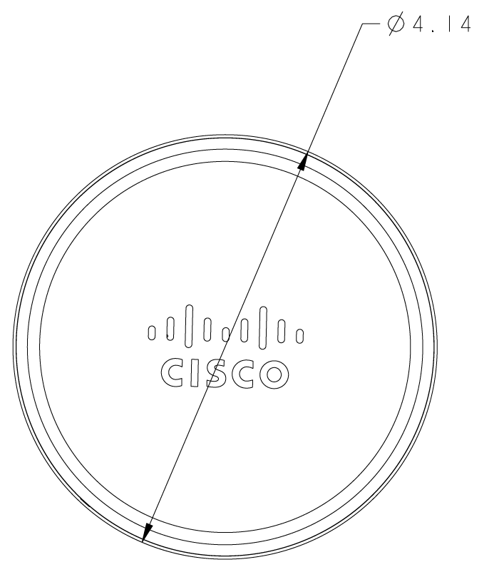
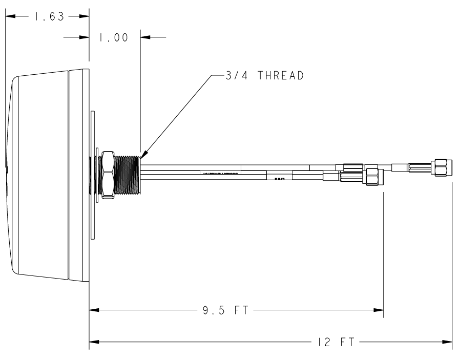
The antenna consists of a single-housing radome measuring 4.14 inches in diameter and 1.63 inches in height. It features a bottom-exiting 3/4" mounting stud (thread), accompanied by an internal tooth lockwasher and a 3/4" jam nut to secure the unit to the mounting surface.


Note


The cellular elements include a built-in ground plane, making the antenna performance independent of the external mounting surface ground plane.
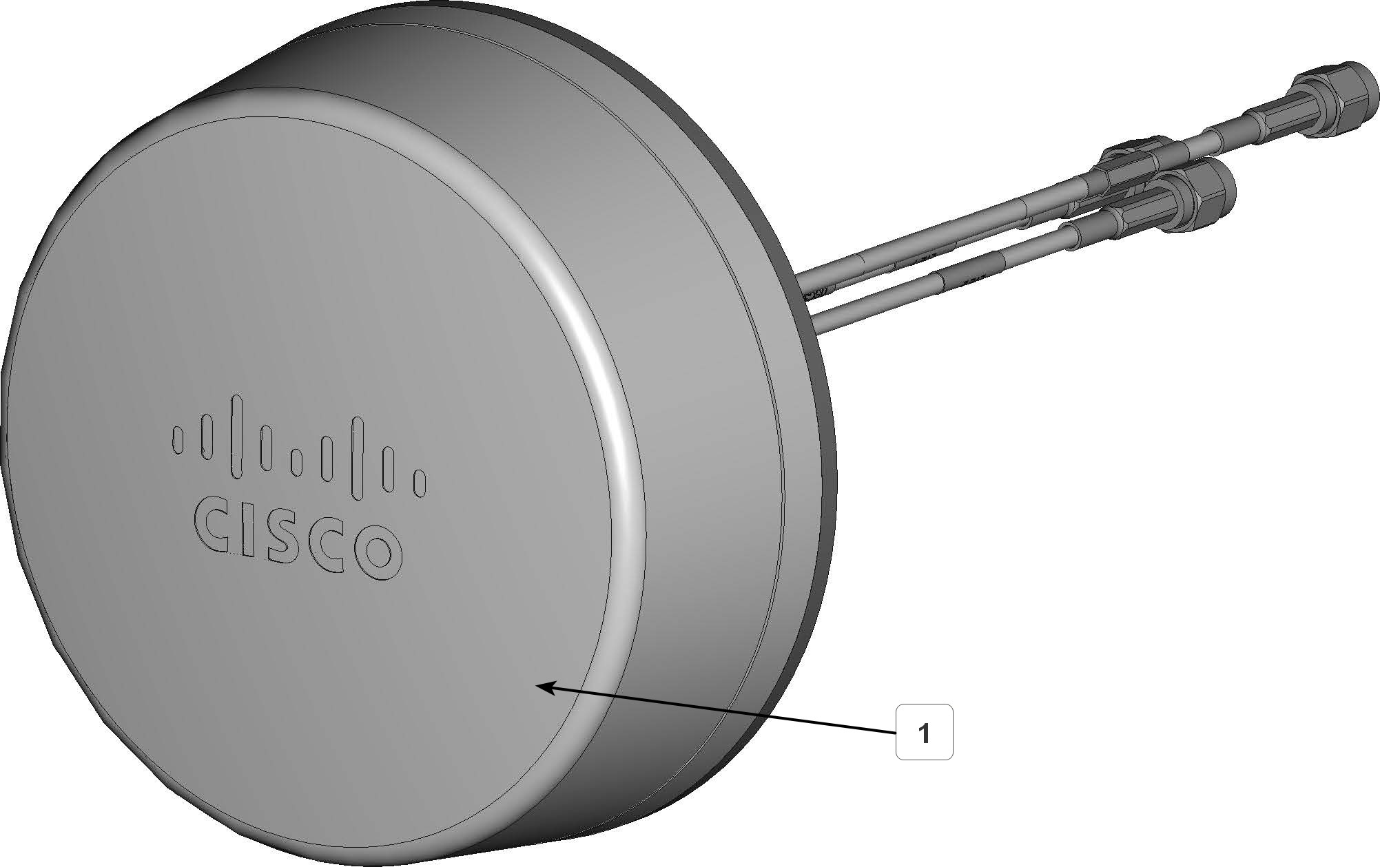
Figure 1. Top View

1

Radome

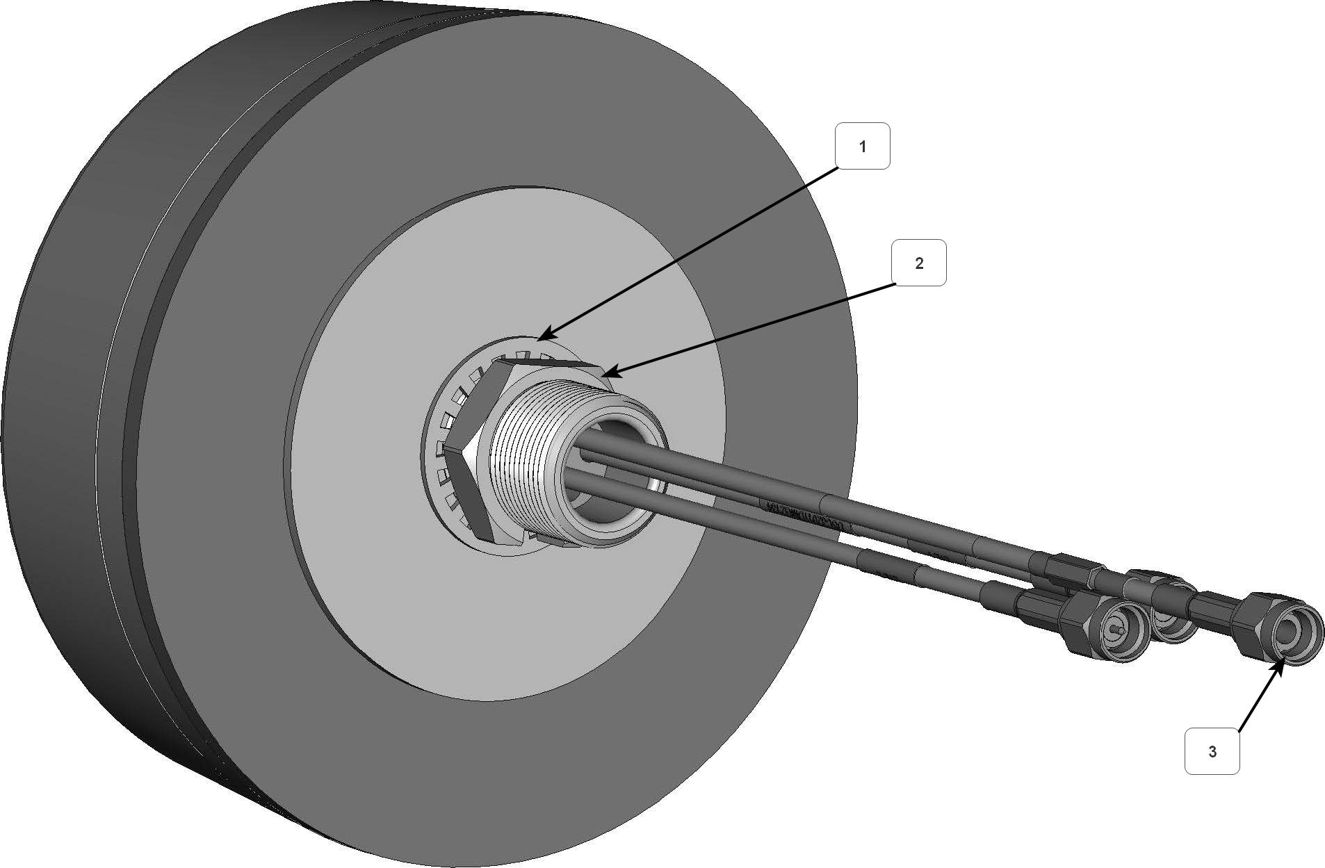
Figure 2. Bottom View

1

Internal tooth washer

2

¾" jam nut

3

3x SMA plugs

Figure 3. Radome Dimensions
Figure 4. Antenna and cable dimensions
Table 1. Mechanical Specifications

Specification

Measurement

Radome Diameter

4.14 in (105.2 mm)

Height

1.63 in (41.4 mm)

Weight

430g (~1 lbs.)

Housing Material

PC, UV Protected

Color

Black

Mounting Thread

3/4 in

Mounting Hole Diameter

0.8 in (20 mm)

Cable and Connector Specifications

The section lists the antenna's cable length, type and connectors.

Table 2. Cable and Connector Specifications

Port Name

Ports

Cable Type

Cable Length

Connector

5G FR1 (Cell 0/1)

2

RG316X

9.5 ft (2896 mm)

SMA Plug (Male)

GNSS (L1/L5)

1

RG316X

12 ft (3658 mm)

SMA Plug (Male)

Electrical Specifications

The following tables provide the electrical specifications for the antenna:

Nominal Impedance

50 Ω

Power Withstanding

20 W

Table 3. Frequency Bands

Frequency Band (MHz)

VSWR (Max)

Peak Gain (Avg)

Polarization

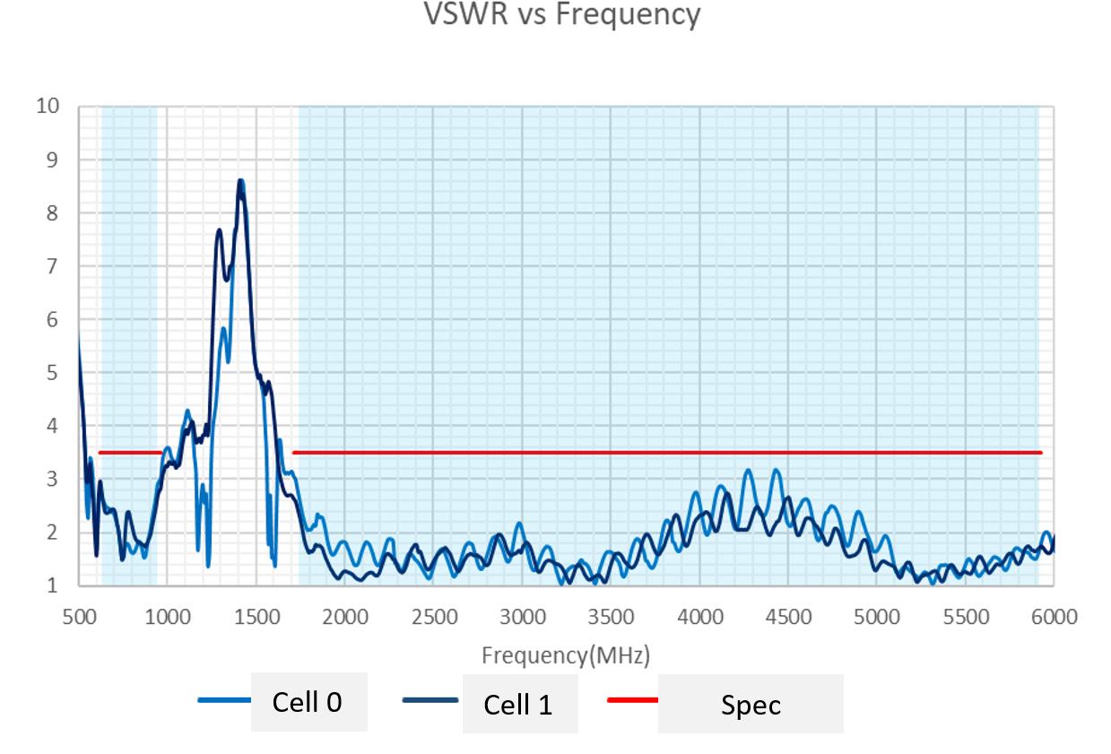
5G: 617-960 MHz

≤3.0:1

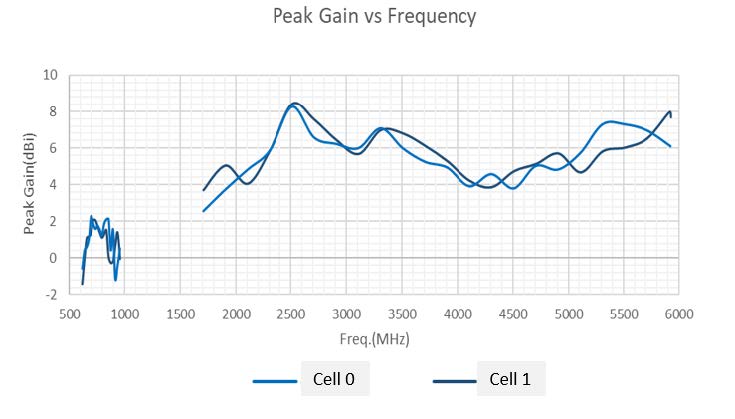
1.9 dBi

Linear

5G: 1700-5900 MHz

≤2.8:1

4.0 dBi

Linear

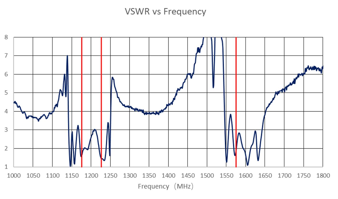
GNSS L1: 1559-1610 MHz

≤2.3:1

2.6 dBic

RHCP

GNSS L5: 1164-1215 MHz

≤2.1:1

2.1 dBic

RHCP

Environmental and Operational Specifications

The following table is a summary of the environmental specifications:

Table 4. Environmental Specifications

Specification

Description

Operating Temperature

–40 to +85°C (–40 to 185°F)

Storage Temperature

–40 to +85°C (–40 to 185°F)

Ingress Protection

IP67

Impact Protection

IK10

Flammability

UL94 5VA

Antenna Installation

This procedure explains how to direct-mount the antenna onto a metal plane or mounting bracket.

Before you begin

Tools and Equipment Required

  • 20 mm (~0.8 in) hole saw or drill bit

  • 1-1/8 inch open-ended wrench

  • Deburring tool


Note


If mounting on a pole, we recommend using the universal mounting bracket kit (ANT-MK-U)


Procedure


Step 1

Drill a 20 mm (~0.8 in) diameter hole through the mounting plane.

Remove all burrs and sharp edges from the hole to protect the cables.

Step 2

Wipe the surface around the hole to ensure proper seating and seal of the integrated gasket.

Step 3

Carefully pass the three SMA plug cables through the hole.

Step 4

Insert the 3/4" threaded mounting stud through the hole until the radome base sits flat against the surface.

Step 5

From the underside of the mounting surface:

  1. slide the internal tooth lockwasher over the cables and thread onto the stud.

  2. slide and hand tighten the 3/4" jam nut.

Step 6

Tighten the jam nut using the 1-1/8 inch open-ended wrench.

Torque the nut to 20–25 N-m (15–18 lb-ft).


The ANT-3-5G2G1-P-O antenna is securedly installed.

What to do next

Connect the 3x SMA cables to the supporting device.

Standalone Antenna Performance

Figure 5. VSWR Vs Frequency
Figure 6. 5G FR1 Peak Gain Vs Frequency
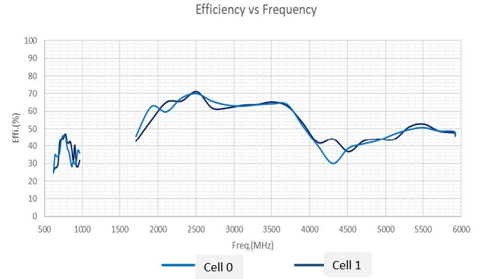
Figure 7. 5G FR1 Efficiency Vs Frequency
Figure 8. GNSS L1/L5 VSWR
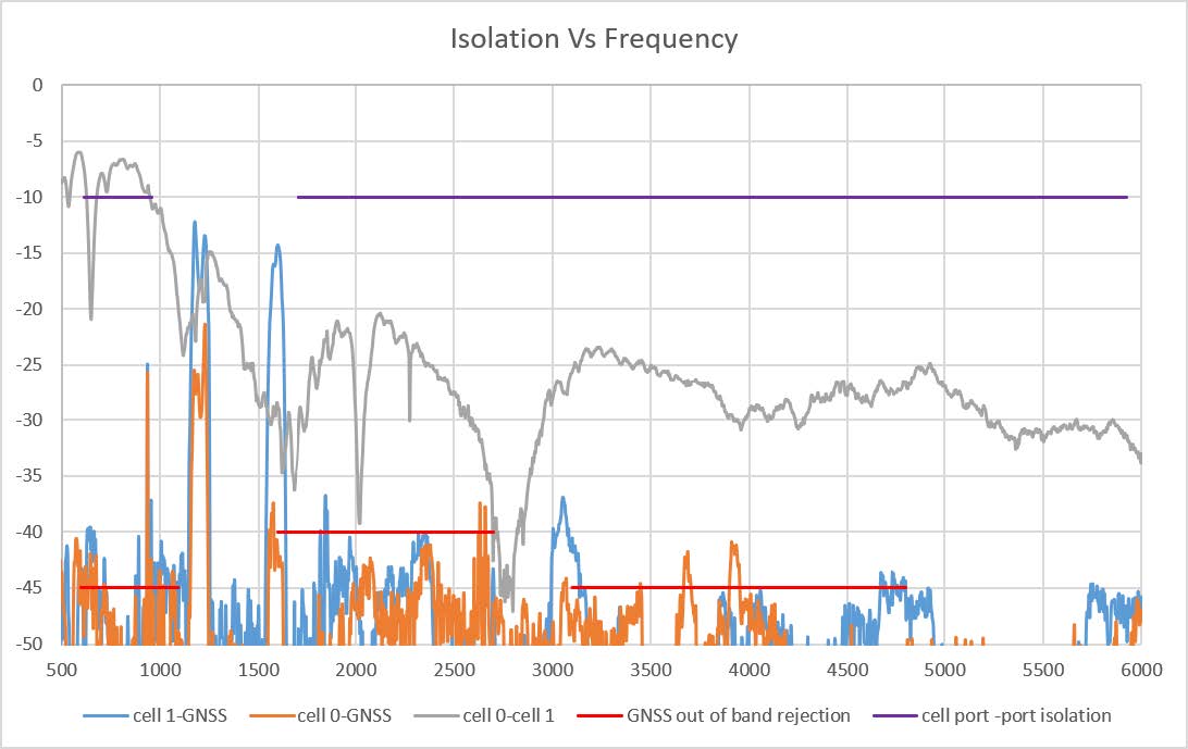
Figure 9. GPS L1/L5 Antenna Isolation
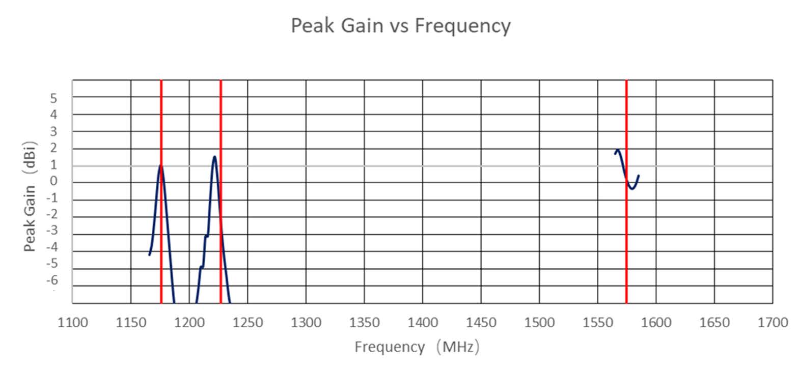
Figure 10. GPS L1/L5 Peak Gain