Cisco Symmetrical Horn Antenna (IW-ANT-H90-510-N)

This chapter contains the following sections:

Overview

The Cisco Symmetrical Horn Antenna (IW-ANT-H90-510-N) offers unique RF performance in a compact package. The horn antenna has a symmetric main beam with identical beamwidth in vertical and horizontal planes.. Exceptionally small side lobes ensure remarkable interference suppression. These antennas are ideal for coverage of areas with clients close to the installation site, where null zone issues exist. High density AP clusters and radio co-location is made possible due to unique radiation patterns and compact size.

These antennas feature multiple improvements of RF performance and design, namely lighter body and significantly improved bracket. The antenna is equipped with N-female connectors.

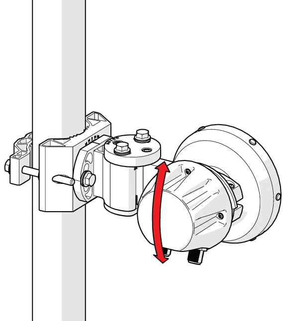
The factory ships this antenna pre-assembled for a left-sided pole mounting configuration.
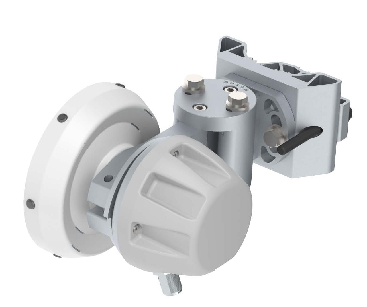
Figure 1. IW-ANT-H90-510-N Antenna

Technical Specifications

The following table is a summary of the technical specifications:

Radio Connection

2x N Female Bulkhead Connector

Antenna Type

Horn

Materials

UV Resistant ABS + PMMA, Aluminium, Zinc Alloy, Stainless Steel

Environmental

IP55

Flame Rating

UL 94 HB

Pole Mounting Diameter

40–80 mm (1.6–3.1 inch)

Recommended as close to 80 mm (3.1 inch) as possible

Temperature

-30°C to +55°C (-22°F to +131°F)

Wind Survival

160 km/h (100 mi/h)

Wind Load

18/11 N - Front/Side at 160 km/h (100 mi/h)

Effective Projected Area

149/94 cm2 - Front/Side (23.1/14.6 in2)

Mechanical Tilt

± 25°

Weight

2.28 kg / 5 lbs

Performance Specifications

The following table is a summary of the performance specifications:

Frequency Range

4900—7150 MHz

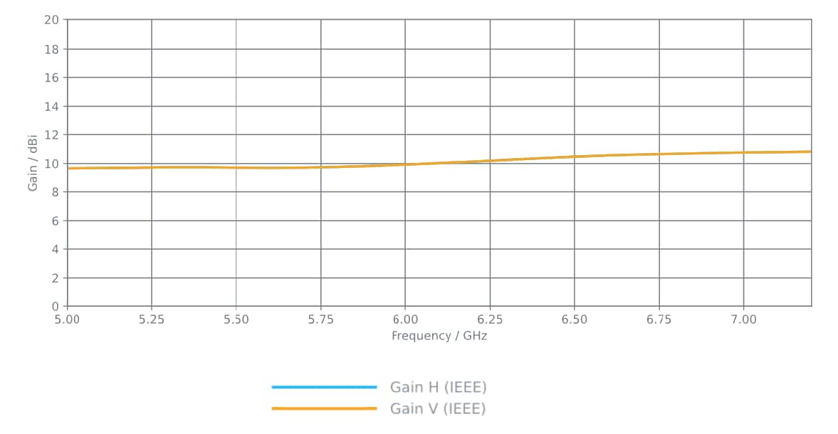
Gain

10 dBi

Azimuth/Elevation BW -3 dB

H 65° / V 65°

Azimuth/Elevation BW -6 dB

H 85° / V 85°

Front-to-Back Ratio

28 dB

VSWR Max

1.5

Beam Efficiency

99.8%

Note

 
Beam efficiency defined up to first null

Polarization

Dual Linear H + V

Impedance

50 Ohm

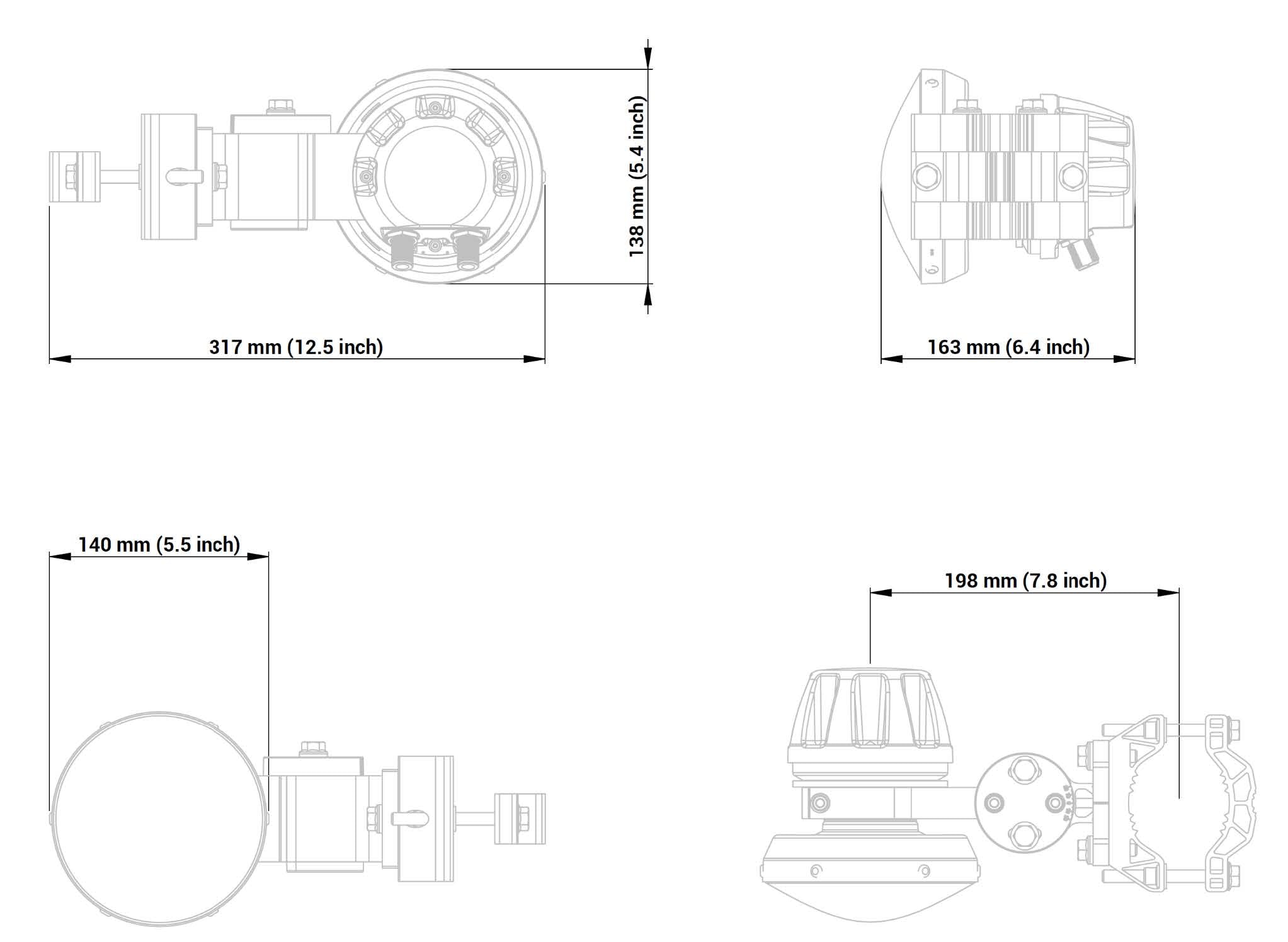
Mechanical Drawing

The following diagram provides mechanical details of the antenna.

Installation Instructions

Before you begin

  • 13 mm socket wrench

  • 10 mm socket wrench

  • 5 mm hex key

  • Pole diameters between 40 mm and 80 mm (1.6 to 3.1 inches)

Procedure


Step 1

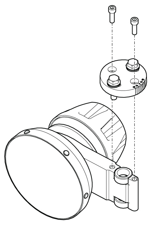
Assemble the Bracket Ring

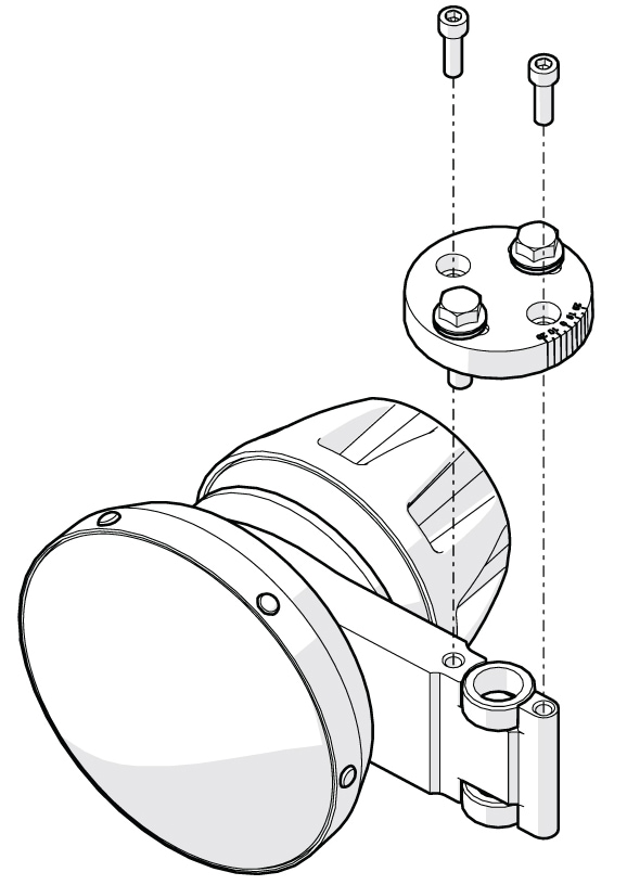
  1. Place the Bracket Ring onto the mounting arm at the rear of the Antenna Body.

  2. Insert the screws and tighten them securely using a 5 mm hex key.

Step 2

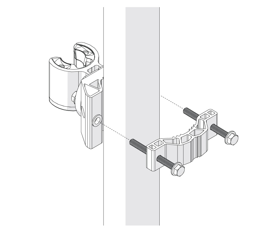
Mount the Bracket to the Pole

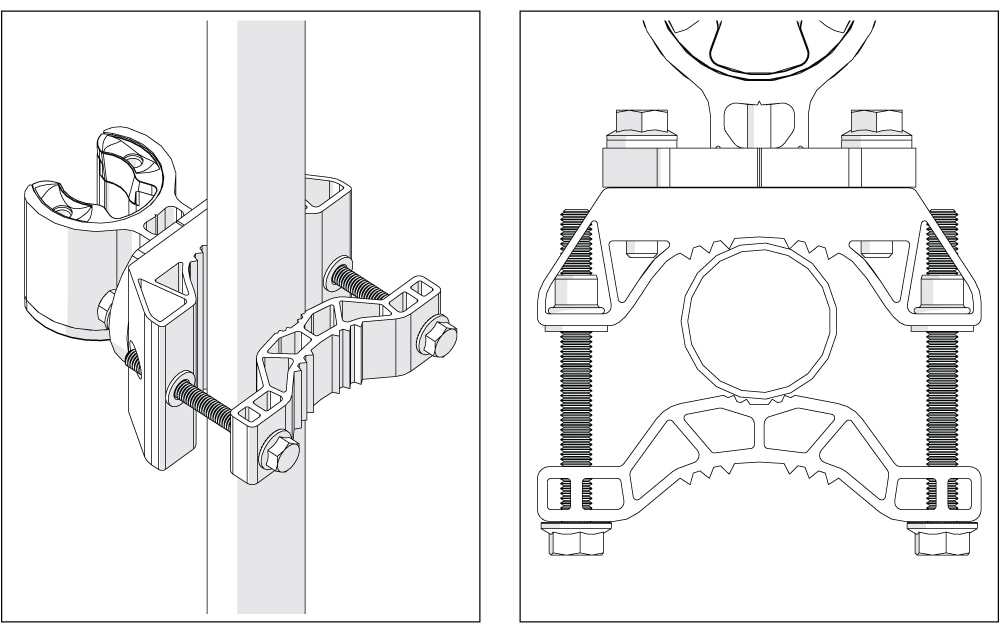
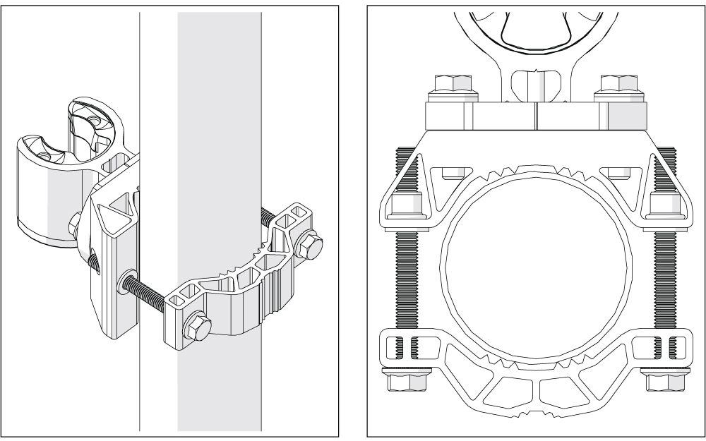
  1. Position the Bracket Base against your mounting pole

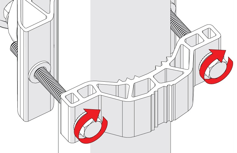
  2. Place the Pole Mount Bracket clamp on the opposite side of the pole

    Note

     
    Orient the bracket clamp based on the pole's diameter.
  3. Insert the long M8 x 80 mm screws through the brackets and tighten the nuts firmly using a 13 mm ratchet wrench

  • Use the narrower gap configuration for a 40–57 mm pole range

  • Use the wider gap configuration for a 58–80 mm pole range

Step 3

Adjust and align the antenna

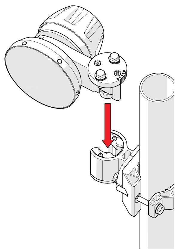
  1. Secure the antenna body to the bracket base.

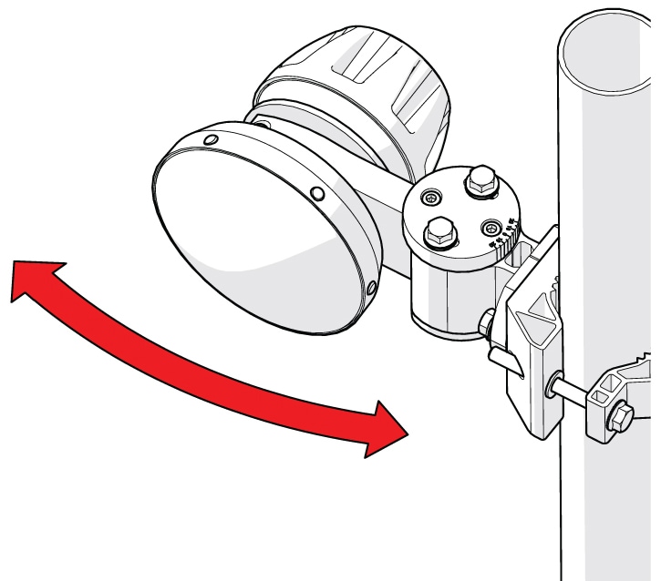
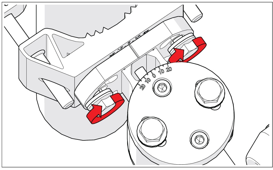
  2. Use the 13 mm ratchet wrench to slightly loosen the alignment bolts on the bracket arm.

  3. Adjust the antenna to your desired heading and tilt angle and tighten the bolts.

  4. Lock the bolts down tightly against the pole.


Custom Antenna Orientation

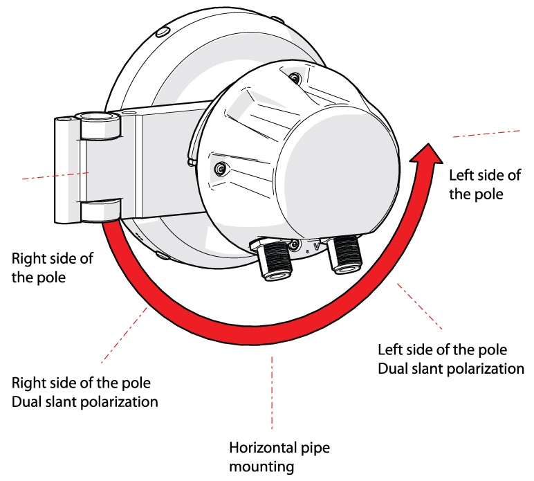
If your deployment requires a custom setup—such as switching the antenna to the right/left side of the pole, configuring it for Horizontal pipe mounting, or setting up Dual slant polarization.

Before you begin

  • 5 mm Hex Key

Procedure


Step 1

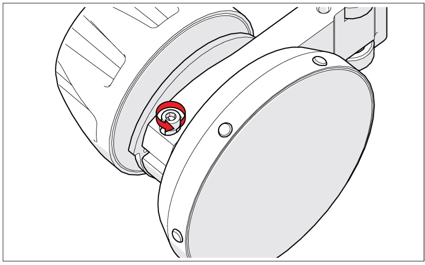
Use a 5 mm Hex Key to release the bracket arm rotation lock

Step 2

Rotate the arm to your desired configuration

The arm positions are detent/indexed to help click it into place accurately.

Step 3

Use the 5 mm Hex Key to tighten and secure the bracket arm back into its new position

Step 4

Re-attach the Bracket Ring to complete the custom orientation


Radiation Patterns

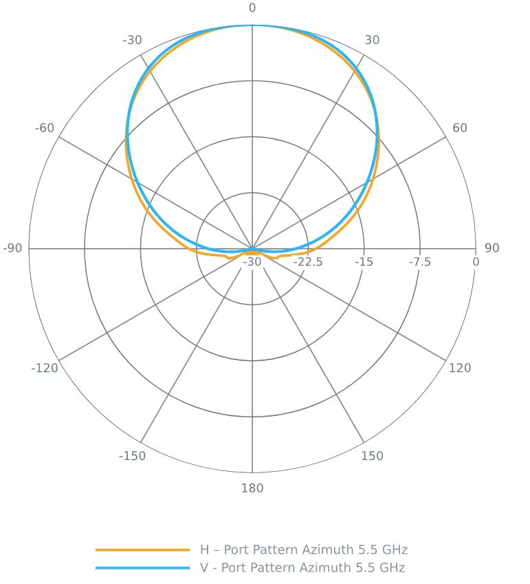
The following figures show the antenna radiation patterns.

Figure 2. Azimuth and Elevation Patterns
Figure 3. Gain