Provisioning Transponder and Muxponder Cards

This chapter describes transponder (TXP), muxponder (MXP), GE_XP, 10GE_XP, GE_XPE, 10GE_XPE, ADM-10G, OTU2_XP, 100G-LC-C, 10x10G-LC, CFP-LC, 100G-CK-C, 100G-ME-C,100ME-CKC, 100GS-CK-LC, 400G-XP-LC, WSE, AR_MXP, AR_XP, and AR_XPE cards, as well as their associated plug-in modules (Small Form-factor Pluggables [SFP, SFP+, XFP, CXP, or CFP module]). For card safety and compliance information, see the Regulatory Compliance and Safety Information for Cisco NCS Platform document.


Note


The cards and procedures described in this chapter are supported on the Cisco NCS 2002 and Cisco NCS 2006 platforms, unless noted otherwise.


Note


Cisco NCS supports IBM's 5G DDR (Double Data Rate) InfiniBand interfaces.

5G DDR InfiniBand is referred to as IB_5G.

Note


When newly installed NCS 2000 cards are provisioned, they initially start in the Standby state. Ensure to provision the card's operating modes, trunk ports, and client ports as required. Change the administrative state of trunk or client ports to "IS," "OOS,MT," or "IS,AINS." Then, the card state will transition from Standby to Active state.


Card Overview

The card overview section lists the cards described in this chapter and provides compatibility information.

The purpose of a TXP, MXP, GE_XP, 10GE_XP, GE_XPE, 10GE_XPE, ADM-10G, OTU2_XP, AR_MXP, AR_XP, or AR_XPE card is to convert the “gray” optical client interface signals into trunk signals that operate in the “colored” dense wavelength division multiplexing (DWDM) wavelength range. Client-facing gray optical signals generally operate at shorter wavelengths, whereas DWDM colored optical signals are in the longer wavelength range (for example, 1490 nm = violet; 1510 nm = blue; 1530 nm = green; 1550 nm = yellow; 1570 nm = orange; 1590 nm = red; 1610 nm = brown). Some of the newer client-facing PPMs, however, operate in the colored region. Transponding or muxponding is the process of converting the signals between the client and trunk wavelengths.

An MXP generally handles several client signals. It aggregates, or multiplexes, lower rate client signals together and sends them out over a higher rate trunk port. Likewise, it demultiplexes optical signals coming in on a trunk and sends them out to individual client ports. A TXP converts a single client signal to a single trunk signal and converts a single incoming trunk signal to a single client signal. GE_XP, 10GE_XP, GE_XPE, and 10GE_XPE cards can be provisioned as TXPs, as MXPs, or as Layer 2 switches.

All of the TXP and MXP cards perform optical to electrical to optical (OEO) conversion. As a result, they are not optically transparent cards. The reason for this is that the cards must operate on the signals passing through them, so it is necessary to do an OEO conversion.

On the other hand, the termination mode for all of the TXPs and MXPs, which is done at the electrical level, can be configured to be transparent. In this case, neither the Line nor the Section overhead is terminated. The cards can also be configured so that either Line or Section overhead can be terminated, or both can be terminated.


Note


The MXP_2.5G_10G card, by design, when configured in the transparent termination mode, actually does terminate some of the bytes. See "Termination Modes" section for details.


Card Compatibility

Table 1. Platform and Software Release Compatibility for Transponder and Muxponder Cards
Card Name

R9.2

R9.2.1

R9.3

R9.4

R9.6.x

R9.8

TXP_MR_10G

15454 - DWDM

15454 - DWDM

15454 - DWDM

15454 - DWDM

15454 - DWDM

15454 - DWDM

TXP_MR_10E

15454 - DWDM

15454 - DWDM

15454 - DWDM

15454 - DWDM

15454 - DWDM

15454 - DWDM

TXP_MR_10E_C

15454 - M2, 15454 - M6, 15454 - DWDM

15454 - M2, 15454 - M6, 15454 - DWDM

15454 - M2, 15454 - M6, 15454 - DWDM

15454 - M2, 15454 - M6, 15454 - DWDM

15454 - M2, 15454 - M6, 15454 - DWDM

15454 - M2, 15454 - M6, 15454 - DWDM

TXP_MR_10E_L

15454 - DWDM

15454 - DWDM

15454 - DWDM

15454 - DWDM

15454 - DWDM

15454 - DWDM

TXP_MR_2.5G and TXPP_MR_2.5G

15454 - M2, 15454 - M6, 15454 - DWDM

15454 - M2, 15454 - M6, 15454 - DWDM

15454 - M2, 15454 - M6, 15454 - DWDM

15454 - M2, 15454 - M6, 15454 - DWDM

15454 - M2, 15454 - M6, 15454 - DWDM

15454 - M2, 15454 - M6, 15454 - DWDM

MXP_2.5G_10G

15454 - DWDM

15454 - DWDM

15454 - DWDM

15454 - DWDM

15454 - DWDM

15454 - DWDM

MXP_2.5G_10E

15454 - DWDM

15454 - DWDM

15454 - DWDM

15454 - DWDM

15454 - DWDM

15454 - DWDM

MXP_2.5G_10E_C

15454 - M2, 15454 - M6, 15454 - DWDM

15454 - M2, 15454 - M6, 15454 - DWDM

15454 - M2, 15454 - M6, 15454 - DWDM

15454 - M2, 15454 - M6, 15454 - DWDM

15454 - M2, 15454 - M6, 15454 - DWDM

15454 - M2, 15454 - M6, 15454 - DWDM

MXP_2.5G_10E_L

15454 - DWDM

15454 - DWDM

15454 - DWDM

15454 - DWDM

15454 - DWDM

15454 - DWDM

MXP_MR_2.5G and MXPP_MR_2.5G

15454 - M2, 15454 - M6, 15454 - DWDM

15454 - M2, 15454 - M6, 15454 - DWDM

15454 - M2, 15454 - M6, 15454 - DWDM

15454 - M2, 15454 - M6, 15454 - DWDM

15454 - M2, 15454 - M6, 15454 - DWDM

15454 - M2, 15454 - M6, 15454 - DWDM

MXP_MR_10DME_C

15454 - M2, 15454 - M6, 15454 - DWDM

15454 - M2, 15454 - M6, 15454 - DWDM

15454 - M2, 15454 - M6, 15454 - DWDM

15454 - M2, 15454 - M6, 15454 - DWDM

15454 - M2, 15454 - M6, 15454 - DWDM

15454 - M2, 15454 - M6, 15454 - DWDM

MXP_MR_10DME_L

15454 - DWDM

15454 - DWDM

15454 - DWDM

15454 - DWDM

15454 - DWDM

15454 - DWDM

GE_XP and 10GE_XP

15454 - M2, 15454 - M6, 15454 - DWDM

15454 - M2, 15454 - M6, 15454 - DWDM

15454 - M2, 15454 - M6, 15454 - DWDM

15454 - M2, 15454 - M6, 15454 - DWDM

15454 - M2, 15454 - M6, 15454 - DWDM

15454 - M2, 15454 - M6, 15454 - DWDM

GE_XPE and 10GE_XPE

15454 - M2, 15454 - M6, 15454 - DWDM

15454 - M2, 15454 - M6, 15454 - DWDM

15454 - M2, 15454 - M6, 15454 - DWDM

15454 - M2, 15454 - M6, 15454 - DWDM

15454 - M2, 15454 - M6, 15454 - DWDM

15454 - M2, 15454 - M6, 15454 - DWDM

ADM - 10G

15454 - M2, 15454 - M6, 15454 - DWDM

15454 - M2, 15454 - M6, 15454 - DWDM

15454 - M2, 15454 - M6, 15454 - DWDM

15454 - M2, 15454 - M6, 15454 - DWDM

15454 - M2, 15454 - M6, 15454 - DWDM

15454 - M2, 15454 - M6, 15454 - DWDM

OTU2_XP

15454 - M2, 15454 - M6, 15454 - DWDM

15454 - M2, 15454 - M6, 15454 - DWDM

15454 - M2, 15454 - M6, 15454 - DWDM

15454 - M2, 15454 - M6, 15454 - DWDM

15454 - M2, 15454 - M6, 15454 - DWDM

15454 - M2, 15454 - M6, 15454 - DWDM

TXP_MR_10EX_C, MXP_2.5G_10EX_C, and MXP_MR_10DMEX_C

15454 - M2, 15454 - M6, 15454 - DWDM

15454 - M2, 15454 - M6, 15454 - DWDM

15454 - M2, 15454 - M6, 15454 - DWDM

15454 - M2, 15454 - M6, 15454 - DWDM

15454 - M2, 15454 - M6, 15454 - DWDM

15454 - M2, 15454 - M6, 15454 - DWDM

40E - TXP - C, 40ME - TXP - C, 40E - MXP - C, and 40ME - MXP - C

No

15454 - M2, 15454 - M6, 15454 - DWDM

15454 - M2, 15454 - M6, 15454 - DWDM

15454 - M2, 15454 - M6, 15454 - DWDM

15454 - M2, 15454 - M6, 15454 - DWDM

15454 - M2, 15454 - M6, 15454 - DWDM

40E - MXP - C

No

15454 - M2, 15454 - M6, 15454 - DWDM

15454 - M2, 15454 - M6, 15454 - DWDM

15454 - M2, 15454 - M6, 15454 - DWDM

15454 - M2, 15454 - M6, 15454 - DWDM

15454 - M2, 15454 - M6, 15454 - DWDM

40G - MXP - C

15454-M2, 15454-M6, 15454-DWDM

15454 - M2, 15454 - M6, 15454 - DWDM

15454 - M2, 15454 - M6, 15454 - DWDM

15454 - M2, 15454 - M6, 15454 - DWDM

15454 - M2, 15454 - M6, 15454 - DWDM

15454 - M2, 15454 - M6, 15454 - DWDM

AR_XP

No No No

15454 - M2, 15454 - M6, 15454 - DWDM

15454 - M2, 15454 - M6, 15454 - DWDM

15454 - M2, 15454 - M6, 15454 - DWDM

AR_MXP and AR_XPE

No

No

No

No

15454 - M2, 15454 - M6, 15454 - DWDM

15454 - M2, 15454 - M6, 15454 - DWDM

100G - LC - C, 100G - ME-C, and 10x10G-LC

No

No

No

No

15454 - M2, 15454 - M6

15454 - M2, 15454 - M6

CFP-LC

No

No

No

No

15454 - M6

15454 - M6

WSE

No

No

No

No

No

15454 - M2, 15454 - M6

100GS-CK-LC

No

No

No

No

No

No

200G-CK-LC

No

No

No

No

No

No

MR-MXP

No

No

No

No

No

No

100ME-CKC

No

No

No

No

No

No

100G-CK-C

No

No

No

No

No

No

400G-XP-LC

No

No

No

No

No

No

Table 2. Platform and Software Release Compatibility for Transponder and Muxponder Cards

Card Name

R10.0

R10.1

R10.3

R10.5

R10.5.2

R10.6.1/10.6.2

R10.7 - R10.9

R11.x.x

TXP_MR_10E_C

NCS 2002, NCS 2006

NCS 2002, NCS 2006

NCS 2002, NCS 2006

NCS 2002, NCS 2006

NCS 2002, NCS 2006

NCS 2002, NCS 2006

NCS 2002, NCS 2006

NCS 2002, NCS 2006

TXP_MR_10E_L

NCS 2002, NCS 2006

NCS 2002, NCS 2006

NCS 2002, NCS 2006

NCS 2002, NCS 2006

NCS 2002, NCS 2006

NCS 2002, NCS 2006

NCS 2002, NCS 2006

NCS 2002, NCS 2006

TXP_MR_10E

NCS 2002, NCS 2006

NCS 2002, NCS 2006

NCS 2002, NCS 2006

NCS 2002, NCS 2006

NCS 2002, NCS 2006, NCS 2015

NCS 2002, NCS 2006, NCS 2015

NCS 2002, NCS 2006, NCS 2015

NCS 2002, NCS 2006, NCS 2015

TXP_MR_2.5G, TXPP_MR_2.5G

NCS 2002, NCS 2006

NCS 2002, NCS 2006

NCS 2002, NCS 2006

NCS 2002, NCS 2006

NCS 2002, NCS 2006

NCS 2002, NCS 2006

NCS 2002, NCS 2006

NCS 2002, NCS 2006

MXP_2.5G_10G

NCS 2002, NCS 2006

NCS 2002, NCS 2006

NCS 2002, NCS 2006

NCS 2002, NCS 2006

NCS 2002, NCS 2006

NCS 2002, NCS 2006

NCS 2002, NCS 2006

NCS 2002, NCS 2006

MXP_2.5G_10E_C

NCS 2002, NCS 2006

NCS 2002, NCS 2006

NCS 2002, NCS 2006

NCS 2002, NCS 2006

NCS 2002, NCS 2006

NCS 2002, NCS 2006

NCS 2002, NCS 2006

NCS 2002, NCS 2006

MXP_2.5G_ 10E_L

NCS 2002, NCS 2006

NCS 2002, NCS 2006

NCS 2002, NCS 2006

NCS 2002, NCS 2006

NCS 2002, NCS 2006

NCS 2002, NCS 2006

NCS 2002, NCS 2006

NCS 2002, NCS 2006

MXP_MR_2.5G, MXPP_ MR_2.5G

NCS 2002, NCS 2006

NCS 2002, NCS 2006

NCS 2002, NCS 2006

NCS 2002, NCS 2006

NCS 2002, NCS 2006

NCS 2002, NCS 2006

NCS 2002, NCS 2006

NCS 2002, NCS 2006

MXP_MR_ 10DME_C

NCS 2002, NCS 2006

NCS 2002, NCS 2006

NCS 2002, NCS 2006

NCS 2002, NCS 2006

NCS 2002, NCS 2006

NCS 2002, NCS 2006

NCS 2002, NCS 2006

(From R10.8) NCS 2015

NCS 2002, NCS 2006

(From R10.8) NCS 2015

MXP_MR_10DME_L

NCS 2002, NCS 2006

NCS 2002, NCS 2006

NCS 2002, NCS 2006

NCS 2002, NCS 2006

NCS 2002, NCS 2006

NCS 2002, NCS 2006

NCS 2002, NCS 2006

NCS 2002, NCS 2006

GE_XP and 10GE_XP

NCS 2002, NCS 2006

NCS 2002, NCS 2006

NCS 2002, NCS 2006

NCS 2002, NCS 2006

NCS 2002, NCS 2006

NCS 2002, NCS 2006

NCS 2002, NCS 2006

(From R10.8) NCS 2015

NCS 2002, NCS 2006

(From R10.8) NCS 2015

GE_XPE and 10GE_XPE

NCS 2002, NCS 2006

NCS 2002, NCS 2006

NCS 2002, NCS 2006

NCS 2002, NCS 2006

NCS 2002, NCS 2006

NCS 2002, NCS 2006

NCS 2002, NCS 2006

(From R10.8) NCS 2015

NCS 2002, NCS 2006

(From R10.8) NCS 2015

ADM-10G

NCS 2002, NCS 2006

NCS 2002, NCS 2006

NCS 2002, NCS 2006

NCS 2002, NCS 2006

NCS 2002, NCS 2006

NCS 2002, NCS 2006

NCS 2002, NCS 2006

NCS 2002, NCS 2006

OTU2_XP

NCS 2002, NCS 2006

NCS 2002, NCS 2006

NCS 2002, NCS 2006

NCS 2002, NCS 2006

NCS 2002, NCS 2006, NCS 2015

NCS 2002, NCS 2006, NCS 2015

NCS 2002, NCS 2006, NCS 2015

NCS 2002, NCS 2006, NCS 2015

TXP_MR_10EX_C, MXP_2.5G_ 10EX_C, MXP_MR_ 10DMEX_C

NCS 2002, NCS 2006

NCS 2002, NCS 2006

NCS 2002, NCS 2006

NCS 2002, NCS 2006

NCS 2002, NCS 2006

NCS 2002, NCS 2006

NCS 2002, NCS 2006

NCS 2002, NCS 2006

40E-TXP-C, 40ME-TXP-C, 40ME-MXP-C

NCS 2002, NCS 2006

NCS 2002, NCS 2006

NCS 2002, NCS 2006

NCS 2002, NCS 2006

NCS 2002, NCS 2006

NCS 2002, NCS 2006

NCS 2002, NCS 2006

NCS 2002, NCS 2006

40E-MXP-C

NCS 2002, NCS 2006

NCS 2002, NCS 2006

NCS 2002, NCS 2006

NCS 2002, NCS 2006

NCS 2002, NCS 2006, NCS 2015

NCS 2002, NCS 2006, NCS 2015

NCS 2002, NCS 2006, NCS 2015

NCS 2002, NCS 2006, NCS 2015

40G-MXP-C

NCS 2002, NCS 2006

NCS 2002, NCS 2006

NCS 2002, NCS 2006

NCS 2002, NCS 2006

NCS 2002, NCS 2006

NCS 2002, NCS 2006

NCS 2002, NCS 2006

NCS 2002, NCS 2006

AR_XP

NCS 2002, NCS 2006

NCS 2002, NCS 2006

NCS 2002, NCS 2006

NCS 2002, NCS 2006

NCS 2002, NCS 2006, NCS 2015

NCS 2002, NCS 2006, NCS 2015

NCS 2002, NCS 2006, NCS 2015

NCS 2002, NCS 2006, NCS 2015

AR_MXP, AR_XPE

NCS 2002, NCS 2006

NCS 2002, NCS 2006

NCS 2002, NCS 2006

NCS 2002, NCS 2006, NCS 2015

NCS 2002, NCS 2006, NCS 2015

NCS 2002, NCS 2006, NCS 2015

NCS 2002, NCS 2006, NCS 2015

NCS 2002, NCS 2006, NCS 2015

100G-LC-C, 100G-ME-C, 10x10G-LC

NCS 2002, NCS 2006

NCS 2002, NCS 2006

NCS 2002, NCS 2006

NCS 2002, NCS 2006, NCS 2015

NCS 2002, NCS 2006, NCS 2015

NCS 2002, NCS 2006, NCS 2015

NCS 2002, NCS 2006, NCS 2015

NCS 2002, NCS 2006, NCS 2015

CFP-LC

NCS 2006

NCS 2006

NCS 2006

NCS 2006

NCS 2006, NCS 2015

NCS 2006, NCS 2015

NCS 2006, NCS 2015

NCS 2006, NCS 2015

WSE

NCS 2002, NCS 2006

NCS 2002, NCS 2006

NCS 2002, NCS 2006

NCS 2002, NCS 2006, NCS 2015

NCS 2002, NCS 2006, NCS 2015

NCS 2002, NCS 2006, NCS 2015

NCS 2002, NCS 2006, NCS 2015

NCS 2002, NCS 2006, NCS 2015

100G-CK-LC, 100ME-CK-LC

NCS 2002, NCS 2006

NCS 2002, NCS 2006

NCS 2002, NCS 2006

NCS 2002, NCS 2006

NCS 2002, NCS 2006

NCS 2002, NCS 2006

NCS 2002, NCS 2006

NCS 2002, NCS 2006

100GS-CK-LC

No

NCS 2002, NCS 2006

NCS 2002, NCS 2006

NCS 2002, NCS 2006, NCS 2015

NCS 2002, NCS 2006, NCS 2015

NCS 2002, NCS 2006, NCS 2015

NCS 2002, NCS 2006, NCS 2015

NCS 2002, NCS 2006, NCS 2015

200G-CK-LC

No

No

NCS 2002, NCS 2006

NCS 2002, NCS 2006, NCS 2015

NCS 2002, NCS 2006, NCS 2015

NCS 2002, NCS 2006, NCS 2015

NCS 2002, NCS 2006, NCS 2015

NCS 2002, NCS 2006, NCS 2015

MR-MXP

No

No

NCS 2002, NCS 2006

NCS 2002, NCS 2006, NCS 2015

NCS 2002, NCS 2006, NCS 2015

NCS 2002, NCS 2006, NCS 2015

NCS 2002, NCS 2006, NCS 2015

NCS 2002, NCS 2006, NCS 2015

100ME-CKC

NCS 2002, NCS 2006

NCS 2002, NCS 2006

NCS 2002, NCS 2006

NCS 2002, NCS 2006, NCS 2015

NCS 2002, NCS 2006, NCS 2015

NCS 2002, NCS 2006, NCS 2015

NCS 2002, NCS 2006, NCS 2015

NCS 2002, NCS 2006, NCS 2015

100G-CK-C

NCS 2002, NCS 2006

NCS 2002, NCS 2006

NCS 2002, NCS 2006

NCS 2002, NCS 2006, NCS 2015

NCS 2002, NCS 2006, NCS 2015

NCS 2002, NCS 2006, NCS 2015

NCS 2002, NCS 2006, NCS 2015

NCS 2002, NCS 2006, NCS 2015

400G-XP-LC

No

No

No

No

No

NCS 2006, NCS 2015

NCS 2002, NCS 2006, NCS 2015

NCS 2002, NCS 2006, NCS 2015

Version Number Compatibility for Transponder and Muxponder Cards

Older versions of the TXP_MR_10E_C, TXP_MR_2.5G, TXPP_MR_2.5G, and MXP_2.5G_10E_C cards cannot be installed in the Cisco NCS 2002 and Cisco NCS 2006 shelves because of an incompatible backplane connector.

The following table describes the version numbers of the cards that are compatible with the Cisco NCS 2002 and Cisco NCS 2006 shelves. The version numbers can be viewed from the HW Rev field in the Inventory tab.

Table 3. Version Number Compatibility
Card Version Number
TXP_MR_2.5G Version 06 or later of the different unit part number
TXPP_MR_2.5G Version 06 or later of the different unit part number
MXP_2.5G_10E_C Version 04 or later of the 800-26774 part number
TXP_MR_10E_C Version 04 or later of the 800-26772 part number

Safety Labels

For information about safety labels, see the "Safety Labels" section.

Interface Classes

The input interface cards have been grouped in classes listed in the following table. The subsequent tables list the optical performance and output power of each interface class.

Table 4. Card Interfaces Assigned to Input Power Classes

Input Power Class

Card

A

10-Gbps multirate transponder cards (TXP_MR_10G, TXP_MR_10E, TXP_MR_10E_C, and TXP_MR_10E_L) with forward error correction (FEC) enabled, 10-Gbps muxponder cards (MXP_2.5G_10G, MXP_2.5G_10E, MXP_MR_10DME_C, MXP_MR_10DME_L, MXP_2.5G_10E_C, and MXP_2.5G_10E_L) with FEC enabled, 40-Gbps transponder cards (40E-TXP-C, and 40ME-TXP-C), and 40-Gbps muxponder cards (40G-MXP-C, 40E-MXP-C, and 40ME-MXP-C)

B

10-Gbps multirate transponder card (TXP_MR_10G) without FEC and the 10-Gbps muxponder card (MXP_2.5G_10G, MXP_MR_10DME_C, MXP_MR_10DME_L), 40-Gbps transponder cards (40E-TXP-C, and 40ME-TXP-C), and 40-Gbps muxponder cards (40G-MXP-C, 40E-MXP-C, and 40ME-MXP-C), and ADM-10G cards with FEC disabled

C

OC-192 LR ITU cards without FEC, 10-Gbps multirate transponder (TXP_MR_10E, TXP_MR_10E_C, and TXP_MR_10E_L) and muxponder (MXP_2.5G_10E, MXP_2.5G_10E_L, and MXP_MR_10DME_L) cards with FEC disabled

D

2.5-Gbps multirate transponder card (TXP_MR_2.5G), both protected and unprotected, with FEC enabled

E

OC-48 100-GHz dense wavelength division multiplexing (DWDM) muxponder card (MXP_MR_2.5G) and 2.5-Gbps multirate transponder card (TXP_MR_2.5G), protected or unprotected; FEC disabled; and retime, reshape, and regenerate (3R) mode enabled

F

2.5-Gbps multirate transponder card (TXP_MR_2.5G), protected or unprotected, in regenerate and reshape (2R) mode

G

OC-48 ELR 100 GHz card

H

2/4 port GbE transponder (GBIC WDM 100GHz)

I

10-Gbps multirate transponder cards (TXP_MR_10E, TXP_MR_10E_C, and TXP_MR_10E_L) and 10-Gbps muxponder cards (MXP_2.5G_10E, MXP_2.5G_10E_L, and MXP_MR_10DME_L) with enhanced FEC (E-FEC) enabled, 40-Gbps transponder cards (40E-TXP-C, and 40ME-TXP-C), and 40-Gbps muxponder cards (40G-MXP-C, 40G-MXP-C, 40E-MXP-C, and 40ME-MXP-C) with E-FEC enabled

K

OC-192/STM-64 LR ITU cards without FEC, 100GHz 10Gbps Ethernet Xponder (GE_XP, GE_XPE, 10GE_XP, 10GE_XPE), Sonet/SDH add/drop (ADM_10G), OTU2 Xponder (OTU2_XP), with FEC disabled

L

40Gbps Duobinary CRS-1 DWDM ITU-T line card

M

2.5 Gbps DWDM ITU-T SPF

N

10Gbps enhanced full tunable transponder (TXP_MR_10E_C) and muxponder (MXP_2.5G_10E_C, MXP_MR_10DME_C) with E-FEC enabled

O

10Gbps Ethernet Xponder (GE_XP, GE_XPE, 10GE_XP, 10GE_XPE), 10Gbps Sonet/SDH add/drop (ADM_10G), OTU2 Xponder (OTU2_XP), with FEC enabled

P

10Gbps Ethernet Xponder (GE_XP, GE_XPE, 10GE_XP, 10GE_XPE), 10Gbps Sonet/SDH add/drop (ADM_10G), OTU2 Xponder (OTU2_XP), with E-FEC enabled

T

40Gbps DPSK CRS-1 DWDM ITU-T line card

V

OC-192/STM-64 LR ITU cards without FEC, full tunable 10Gbps Ethernet Xponder (GE_XP, GE_XPE, 10GE_XP, 10GE_XPE), Sonet/SDH add/drop (ADM_10G), OTU2 Xponder (OTU2_XP), with FEC disabled, full tunable

W

10Gbps Ethernet Xponder (GE_XP, GE_XPE, 10GE_XP, 10GE_XPE), Sonet/SDH add/drop (ADM_10G), OTU2 Xponder (OTU2_XP), with FEC enabled, full tunable

X

10Gbps Ethernet Xponder (GE_XP, GE_XPE, 10GE_XP, 10GE_XPE), Sonet/SDH add/drop (ADM_10G), OTU2 Xponder (OTU2_XP), with E-FEC enabled, full tunable

Y

10Gbps enhanced full tunable transponder (TXP_MR_10EX_C) and muxponder (MXP_2.5G_10EX_C, MXP_MR_10DMEX_C), with FEC enabled and maximum likelihood sequence estimator (MLSE) correction

Z

10Gbps enhanced full tunable transponder (TXP_MR_10EX_C) and muxponder (MXP_2.5G_10EX_C, MXP_MR_10DMEX_C), with E-FEC enabled and MLSE correction

Table 5. 40-Gbps Interface Optical Performance

Parameter

Class A

Class B

Class I

Type

Power Limited

OSNR Limited
(if appl.)

OSNR = optical signal-to-noise ratio

Power Limited

OSNR Limited
(if appl.)

Power Limited

OSNR Limited
(if appl.)

Maximum bit rate

40 Gbps

40 Gbps

40 Gbps

Regeneration

3R

3R

3R

FEC

Yes

No

Yes (E-FEC)

Threshold

Optimum

Average

Optimum

Maximum BER

BER = bit error rate

10–15

10–12

10–15

OSNR sensitivity

OSNR = optical signal-to-noise ratio

23 dB

9 dB

23 dB

19 dB

20 dB

8 dB

Power sensitivity

–24 dBm

–18 dBm

–21 dBm

–20 dBm

–26 dBm

–18 dBm

Power overload

–8 dBm

–8 dBm

–8 dBm

Transmitted Power Range—These values, decreased by patchcord and connector losses, are also the input power values for the OADM cards.

40-Gbps multirate transponder/40-Gbps FEC transponder (40E-TXP-C, and 40ME-TXP-C)

+2.5 to 3.5 dBm

+2.5 to 3.5 dBm

OC-192 LR ITU

Dispersion compensation tolerance

+/–800 ps/nm

+/–1,000 ps/nm

+/–800 ps/nm

Table 6. 10-Gbps Interface Optical Performance (Class A, B, C, I, and K)

Parameter

Class A

Class B

Class C

Class I

Class K

Type

Power Limited

OSNR Limited

Power Limited

OSNR Limited

Power Limited

OSNR Limited

Power Limited

OSNR Limited

Power Limited

OSNR Limited

Maximum bit rate

10 Gbps

10 Gbps

10 Gbps

10 Gbps

10 Gbps

Regeneration

3R

3R

3R

3R

3R

FEC

Yes

No

No

Yes (E-FEC)

No

Threshold

Optimum

Average

Average

Optimum

Average

Maximum BER

10–15

10–12

10–12

10–15

10–12

OSNR sensitivity

23 dB

8.5 dB

23 dB

19 dB

19 dB

19 dB

20 dB

6 dB

23 dB

This value is for Xen Pak XFP used with Catalyst card.

16 dB3

23 dB

This value is for XFP used with Catalyst, Xponder, and ADM-10G cards.

17 dB4

23 dB

This value is for X2 XFP used with Catalyst card.

17 dB5

Power sensitivity

–24 dBm

–18 dBm

–21 dBm

–20 dBm

–22 dBm

–22 dBm

–26 dBm

–18 dBm

–24 dBm3

–17 dBm3

–23 dBm4

–18 dBm4

–23 dBm5

–17 dBm5

Power overload

–8 dBm

–8 dBm

–9 dBm

–8 dBm

–7 dBm

Transmitted Power Range—These values, decreased by patchcord and connector losses, are also the input power values for the optical add drop multiplexer (OADM) cards.

10-Gbps multirate transponder /10-Gbps FEC transponder

+2.5 to 3.5 dBm (for TXP_MR_10G)

+3.0 to 6.0 dBm (for TXP_MR_10E)

+2.5 to 3.5 dBm

+3.0 to 6.0 dBm

+3.0 to 6.0 dBm

OC-192 LR ITU

+3.0 to 6.0 dBm

–1.0 to +3.0 dBm

10-Gbps Ethernet Xponder, Sonet/SDH Add/Drop, OTU2 Xponder

–1.0 to +3.0 dBm

Dispersion compensation tolerance

+/–800 ps/nm

+/–1,000 ps/nm

+/–1,000 ps/nm

+/–800 ps/nm

–400 to +800 ps/nm

Table 7. 10-Gbps Interface Optical Performance (Class N, O, P, and V)

Parameter

Class N

Class O

Class P

Class V

Type

Power Limited

OSNR Limited

Power Limited

OSNR Limited

Power Limited

OSNR Limited

Power Limited

OSNR Limited

Maximum bit rate

10 Gbps

10 Gbps

10 Gbps

10 Gbps

Regeneration

3R

3R

3R

3R

FEC

Yes (E-FEC)

Yes

Yes (E-FEC)

No

Threshold

Optimum

Optimum

Optimum

Average

Maximum BER

10–15

10–15

10–15

10–12

OSNR sensitivity

19 dB

5 dB

11 dB

11 dB

23 dB

8 dB

23 dB

16 dB

Power sensitivity

–27 dBm

–20 dBm

–18 dBm

–18 dBm

–27 dBm

–18 dBm

–24 dBm

–18 dBm

Power overload

–8 dBm

–7 dBm

–7 dBm

–7 dBm

Transmitted Power Range—These values, decreased by patchcord and connector losses, are also the input power values for the optical add drop multiplexer (OADM) cards.

10-Gbps multirate transponder/10-Gbps FEC transponder

+3.0 to 6.0 dBm

OC-192 LR ITU

0 to +3.0 dBm

10-Gbps Ethernet Xponder, Sonet/SDH Add/Drop, OTU2 Xponder

–1.0 to +3.0 dBm

–1.0 to +3.0 dBm

0 to +3.0 dBm

Dispersion compensation tolerance

+/–800 ps/nm

–500 to +1100 ps/nm

–500 to +1100 ps/nm

–500 to +1600 ps/nm

Table 8. 10-Gbps Interface Optical Performance (Class W, X, Y, and Z)

Parameter

Class W

Class X

Class Y

Class Z

Type

Power Limited

OSNR Limited

Power Limited

OSNR Limited

Power Limited

OSNR Limited

Power Limited

OSNR Limited

Maximum bit rate

10 Gbps

10 Gbps

10 Gbps

10 Gbps

Regeneration

3R

3R

3R

3R

FEC

Yes

Yes (E-FEC)

Yes

Yes (E-FEC)

Threshold

Optimum

Optimum

Optimum

Optimum

Maximum BER

10–15

10–15

10–15

10–15

OSNR sensitivity

8.5 dB

8.5 dB

19 dB

5 dB

23 dB

8 dB

19 dB

5.5 dB

Power sensitivity

–18 dBm

–18 dBm

–27 dBm

–20 dBm

–24 dBm

–20 dBm

–27 dBm

–20 dBm

Power overload

–7 dBm

–7 dBm

–8 dBm

–8 dBm

Transmitted Power Range—These values, decreased by patchcord and connector losses, are also the input power values for the optical add drop multiplexer (OADM) cards.

10-Gbps multirate transponder/10-Gbps FEC transponder

+3.0 to 6.0 dBm

+3.0 to 6.0 dBm

OC-192 LR ITU

10-Gbps Ethernet Xponder, Sonet/SDH Add/Drop, OTU2 Xponder

0 to +3.0 dBm

0 to +3.0 dBm

Dispersion compensation tolerance

–500 to +1100 ps/nm

–500 to +1300 ps/nm

–800 to +1600 ps/nm

–2200 to +3700 ps/nm

Table 9. 2.5-Gbps Interface Optical Performance (Class D, E, and F)

Parameter

Class D

Class E

Class F

Type

Power Limited

OSNR Limited

Power Limited

OSNR Limited

Power Limited

OSNR Limited

Maximum bit rate

2.5 Gbps

2.5 Gbps

2.5 Gbps

Regeneration

3R

3R

2R

FEC

Yes

No

No

Threshold

Average

Average

Average

Maximum BER

10–15

10–12

10–12

OSNR sensitivity

14 dB

5 dB

14 dB

10 dB

15 dB

15 dB

Power sensitivity

–31 dBm

–25 dBm

–30 dBm

–23 dBm

–24 dBm

–24 dBm

Power overload

–9 dBm

–9 dBm

–9 dBm

Transmitted Power Range—These values, decreased by patchcord and connector losses, are also the input power values for the optical add drop multiplexer (OADM) cards.

TXP_MR_2.5G and TXPP_MR_2.5G

–1.0 to 1.0 dBm

–1.0 to 1.0 dBm

–1.0 to 1.0 dBm

MXP_MR_2.5G and MXPP_MR_2.5G

+2.0 to +4.0 dBm

OC-48 ELR 100 GHz

2/4 port GbE Transponder (GBIC WDM 100GHz)

2.5 Gbps DWDM ITU-T SPF

Dispersion compensation tolerance

–1200 to +5400 ps/nm

–1200 to +5400 ps/nm

–1200 to +3300 ps/nm

Table 10. 2.5-Gbps Interface Optical Performance (Class G, H, and M)

Parameter

Class G

Class H

Class M

Type

Power Limited

OSNR Limited

Power Limited

OSNR Limited

Power Limited

OSNR Limited

Maximum bit rate

2.5 Gbps

1.25 Gbps

2.5 Gbps

Regeneration

3R

3R

3R

FEC

No

No

No

Threshold

Average

Average

Average

Maximum BER

10–12

10–12

10–12

OSNR sensitivity

14 dB

11 dB

13 dB

8 dB

14 dB

9 dB

Power sensitivity

–27 dBm

–23 dBm

–28 dBm

–18 dBm

–28 dBm

–22 dBm

Power overload

–9 dBm

–7 dBm

–9 dBm

Transmitted Power Range—These values, decreased by patchcord and connector losses, are also the input power values for the optical add drop multiplexer (OADM) cards.

TXP_MR_2.5G

TXPP_MR_2.5G

MXP_MR_2.5G

–2.0 to 0 dBm

MXPP_MR_2.5G

OC-48 ELR 100 GHz

2/4 port GbE Transponder (GBIC WDM 100GHz)

–1200 to +3300 ps/nm

0 to +3 dBm

2.5 Gbps DWDM ITU-T SPF

0 to +4 dBm

Dispersion compensation tolerance

–1000 to +3600 ps/nm

–800 to +2400 ps/nm

TXP_MR_10E Card

The card is fully backward compatible with the TXP_MR_10G card. It processes one 10-Gbps signal (client side) into one 10-Gbps, 100-GHz DWDM signal (trunk side) that is tunable over four wavelength channels (spaced at 100 GHz on the ITU grid) in the C band and tunable over eight wavelength channels (spaced at 50 GHz on the ITU grid) in the L band. There are eight versions of the C-band card, with each version covering four wavelengths, for a total coverage of 32 wavelengths. There are five versions of the L-band card, with each version covering eight wavelengths, for a total coverage of 40 wavelengths.

You can install TXP_MR_10E cards in , Slots 2 and 3 in Cisco NCS 2002 chassis, Slots 2 to 7 in Cisco NCS 2006, Slots 2 to 16 in Cisco NCS 2015 chassis and provision the cards in a linear configuration, BLSR/MS-SPRing, path protection/SNCP, or a regenerator. The card can be used in the middle of BLSR/MS-SPRing or 1+1 spans when the card is configured for transparent termination mode.

The TXP_MR_10E card features a 1550-nm tunable laser (C band) or a 1580-nm tunable laser (L band) for the trunk port and ONS-XC-10G-S1 1310-nm or ONS-XC-10G-L2 1550-nm laser XFP module for the client port that can be ordered separately.

When TNCS-2 and TNCS-2O cards are present as control cards, LDCC is not supported for the TXP_MR_10E card.


Note


When the ONS-XC-10G-L2 XFP is installed, the TXP_MR_10E card must be installed in Slots 6, 7, 12, or 13 in the .


On its faceplate, the TXP_MR_10E card contains two transmit and receive connector pairs, one for the trunk port and one for the client port. Each connector pair is labeled.

Key Features

The key features of the TXP_MR_10E card are:

  • A tri-rate client interface (available through the ONS-XC-10G-S1 XFP, ordered separately)

    • OC-192 (SR1)

    • 10GE (10GBASE-LR)

    • 10G-FC (1200-SM-LL-L)

    • IB_5G

  • OC-192 to ITU-T G.709 OTU2 provisionable synchronous and asynchronous mapping

  • The MTU setting is used to display the OverSizePkts counters on the receiving Gigabit Ethernet client port interfaces. Traffic of frame sizes up to 65535 bytes pass without any packet drops, from the client port to the trunk port irrespective of the MTU setting.

TXP_MR_10E_C and TXP_MR_10E_L Cards

The TXP_MR_10E_C and TXP_MR_10E_L cards are fully backward compatible with the TXP_MR_10G and TXP_MR_10E cards. They processes one 10-Gbps signal (client side) into one 10-Gbps, 100-GHz DWDM signal (trunk side). The TXP_MR_10E_C is tunable over the entire set of C-band wavelength channels (82 channels spaced at 50 GHz on the ITU grid). The TXP_MR_10E_L is tunable over the entire set of L-band wavelength channels (80 channels spaced at 50 GHz on the ITU grid) and is particularly well suited for use in networks that employ DS fiber or SMF-28 single-mode fiber.

The advantage of these cards over previous versions (TXP_MR_10G and TXP_MR_10E) is that there is only one version of each card (one C-band version and one L-band version) instead of several versions needed to cover each band.

You can install TXP_MR_10E_C and TXP_MR_10E_L cards in , Slot 2 in Cisco NCS 2002 chassis, Slots 2 to 6 in Cisco NCS 2006 and provision the cards in a linear configuration, BLSR/MS-SPRing, path protection/SNCP, or a regenerator. The cards can be used in the middle of BLSR/MS-SPRing or 1+1 spans when the cards are configured for transparent termination mode.

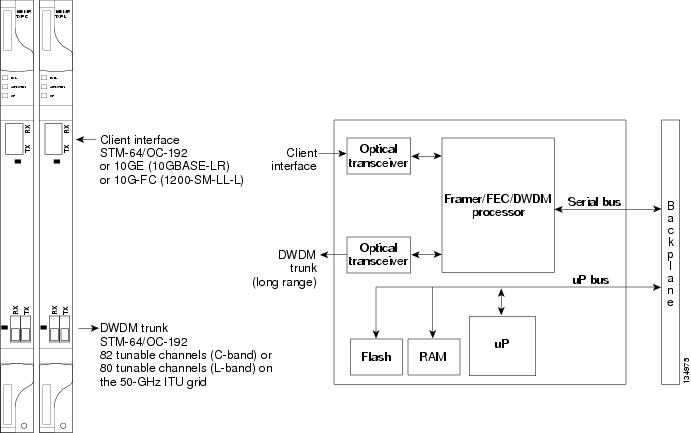
The TXP_MR_10E_C and TXP_MR_10E_L cards feature a universal transponder 2 (UT2) 1550-nm tunable laser (C band) or a UT2 1580-nm tunable laser (L band) for the trunk port and a separately orderable ONS-XC-10G-S1 1310-nm or ONS-XC-10G-L2 1550-nm laser XFP module for the client port.

On its faceplate, the TXP_MR_10E_C and TXP_MR_10E_L cards contain two transmit and receive connector pairs, one for the trunk port and one for the client port. Each connector pair is labeled.

Key Features

The key features of the TXP_MR_10E_C and TXP_MR_10E_L cards are:

  • A tri-rate client interface (available through the ONS-XC-10G-S1 XFP, ordered separately):

    • OC-192 (SR1)

    • 10GE (10GBASE-LR)

    • 10G-FC (1200-SM-LL-L)

  • A UT2 module tunable through the entire C band (TXP_MR_10E_C card) or L band (TXP_MR_10E_L card). The channels are spaced at 50 GHz on the ITU grid.

  • OC-192 to ITU-T G.709 OTU2 provisionable synchronous and asynchronous mapping.

  • The MTU setting is used to display the OverSizePkts counters on the receiving Gigabit Ethernet client port interfaces. Traffic of frame sizes up to 65535 bytes pass without any packet drops, from the client port to the trunk port irrespective of the MTU setting.

For a detailed list of the supported pluggables, see, http://www.cisco.com/c/en/us/td/docs/optical/spares/gbic/guides/b_ncs_pluggables.html

Faceplates and Block Diagram

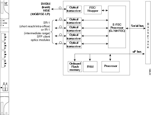
Figure 1. TXP_MR_10E_C and TXP_MR_10E_L Faceplates and Block Diagram

For information about safety labels for the cards, see the "Class 1M Laser Product Cards" section.


Caution


You must use a 15-dB fiber attenuator (10 to 20 dB) when working with the TXP_MR_10E_C or TXP_MR_10E_L card in a loopback on the trunk port. Do not use direct fiber loopbacks with the cards. Using direct fiber loopbacks causes irreparable damage to the cards.


TXP_MR_10E_C and TXP_MR_10E_L Functions

The following functions of the TXP_MR_10E_C and TXP_MR_10E_L cards are explained in "Card Features" chapter:
  • Automatic Laser Shutdown

  • Card level indicators

  • Port level indicators

  • Client Interface

  • DWDM Trunk Interface

  • FEC

  • Client-to-Trunk Mapping

TXP_MR_2.5G and TXPP_MR_2.5G Cards

The TXP_MR_2.5G card processes one 8-Mbps to 2.488-Gbps signal (client side) into one 8-Mbps to 2.5-Gbps, 100-GHz DWDM signal (trunk side). It provides one long-reach STM-16/OC-48 port per card, compliant with ITU-T G.707, ITU-T G.709, ITU-T G.957, and Telcordia GR-253-CORE.

The TXPP_MR_2.5G card processes one 8-Mbps to 2.488-Gbps signal (client side) into two 8-Mbps to 2.5-Gbps, 100-GHz DWDM signals (trunk side). It provides two long-reach STM-16/OC-48 ports per card, compliant with ITU-T G.707, ITU-T G.957, and Telcordia GR-253-CORE.

The TXP_MR_2.5G and TXPP_MR_2.5G cards are tunable over four wavelengths in the 1550-nm, ITU 100-GHz range. They are available in eight versions, each of which covers four wavelengths, for a total coverage of 32 different wavelengths in the 1550-nm range.

For a detailed list of the supported pluggables, see, http://www.cisco.com/c/en/us/td/docs/optical/spares/gbic/guides/b_ncs_pluggables.html


Note


ITU-T G.709 specifies a form of FEC that uses a “wrapper” approach. The digital wrapper lets you transparently take in a signal on the client side, wrap a frame around it, and restore it to its original form. FEC enables longer fiber links because errors caused by the optical signal degrading with distance are corrected.


The trunk/line port operates at up to 2.488 Gbps (or up to 2.66 Gbps with ITU-T G.709 Digital Wrapper/FEC) over unamplified distances up to 360 km (223.7 miles) with different types of fiber such as C-SMF or higher if dispersion compensation is used.


Caution


Because the transponder has no capability to look into the payload and detect circuits, a TXP_MR_2.5G or TXPP_MR_2.5G card does not display circuits under card view.


The TXP_MR_2.5G and TXPP_MR_2.5G cards support 2R (retime, regenerate) and 3R (retime, reshape, and regenerate) modes of operation where the client signal is mapped into a ITU-T G.709 frame. The mapping function is simply done by placing a digital wrapper around the client signal. Only OC-48/STM-16 client signals are fully ITU-T G.709 compliant, and the output bit rate depends on the input client signal. The following table shows the possible combinations of client interfaces, input bit rates, 2R and 3R modes, and ITU-T G.709 monitoring.

Table 11. 2R and 3R Mode and ITU-T G.709 Compliance by Client Interface

Client Interface

Input Bit Rate

3R vs. 2R

ITU-T G.709

OC-48/STM-16

2.488 Gbps

3R

On or Off

DV-6000

2.38 Gbps

2R

2 Gigabit Fibre Channel (2G-FC)/fiber connectivity (FICON)

2.125 Gbps

3R

No monitoring

On or Off

High-Definition Television (HDTV)

1.48 Gbps

2R

Gigabit Ethernet (GE)

1.25 Gbps

3R

On or Off

1 Gigabit Fibre Channel (1G-FC)/FICON

1.06 Gbps

3R

On or Off

OC-12/STM-4

622 Mbps

3R

On or Off

OC-3/STM-1

155 Mbps

3R

On or Off

Enterprise System Connection (ESCON)

200 Mbps

2R

SDI/D1/DVB-ASI video

270 Mbps

2R

ISC-1 Compat

1.06 Gbps

2R

Off

ISC-3

1.06 or 2.125 Gbps

2R

ETR_CLO

16 Mbps

2R


Note


ITU-T G.709 and FEC support is disabled for all the 2R payload types in the TXP_MR_2.5G and TXPP_MR_2.5G cards.


The output bit rate is calculated for the trunk bit rate by using the 255/238 ratio as specified in ITU-T G.709 for OTU1. The following table lists the calculated trunk bit rates for the client interfaces with ITU-T G.709 enabled.

Table 12. Trunk Bit Rates With ITU-T G.709 Enabled

Client Interface

ITU-T G.709 Disabled

ITU-T G.709 Enabled

OC-48/STM-16

2.488 Gbps

2.66 Gbps

2G-FC

2.125 Gbps

2.27 Gbps

GE

1.25 Gbps

1.34 Gbps

1G-FC

1.06 Gbps

1.14 Gbps

OC-12/STM-3

622 Mbps

666.43 Mbps

OC-3/STM-1

155 Mbps

166.07 Mbps

For 2R operation mode, the TXP_MR_2.5G and TXPP_MR_2.5G cards have the ability to pass data through transparently from client side interfaces to a trunk side interface, which resides on an ITU grid. The data might vary at any bit rate from 200-Mbps up to 2.38-Gbps, including ESCON, DVB-ASI, ISC-1, and video signals. In this pass-through mode, no performance monitoring (PM) or digital wrapping of the incoming signal is provided, except for the usual PM outputs from the SFPs. Similarly, this card has the ability to pass data through transparently from the trunk side interfaces to the client side interfaces with bit rates varying from 200-Mbps up to 2.38-Gbps. Again, no PM or digital wrapping of received signals is available in this pass-through mode.

For 3R operation mode, the TXP_MR_2.5G and TXPP_MR_2.5G cards apply a digital wrapper to the incoming client interface signals (OC-N/STM-N, 1G-FC, 2G-FC, GE). PM is available on all of these signals except for 2G-FC, and varies depending upon the type of signal. For client inputs other than OC-48/STM-16, a digital wrapper might be applied but the resulting signal is not ITU-T G.709 compliant. The card applies a digital wrapper that is scaled to the frequency of the input signal.

The TXP_MR_2.5G and TXPP_MR_2.5G cards have the ability to take digitally wrapped signals in from the trunk interface, remove the digital wrapper, and send the unwrapped data through to the client interface. PM of the ITU-T G.709 OH and SONET/SDH OH is implemented.

You can install TXP_MR_2.5G and TXPP_MR_2.5G cards in , Slots 2 and 3 in Cisco NCS 2002 chassis, Slots 2 to 7 in Cisco NCS 2006. You can provision this card in a linear configuration. TXP_MR_10G and TXPP_MR_2.5G cards cannot be provisioned as a BLSR/MS-SPRing, a path protection/SNCP, or a regenerator. They can be used in the middle of BLSR/MS-SPRing or 1+1 spans only when the card is configured for transparent termination mode.

The TXP_MR_2.5G card features a 1550-nm laser for the trunk/line port and a 1310-nm laser for the client port. It contains two transmit and receive connector pairs (labeled) on the card faceplate. The card uses dual LC connectors for optical cable termination.

The TXPP_MR_2.5G card features a 1550-nm laser for the trunk/line port and a 1310-nm or 850-nm laser (depending on the SFP) for the client port and contains three transmit and receive connector pairs (labeled) on the card faceplate. The card uses dual LC connectors for optical cable termination.

40E-TXP-C and 40ME-TXP-C Cards

The 40E-TXP-C and 40ME-TXP-C cards process a single 40-Gbps signal (client side) into a single 40-Gbps, 50-GHz DWDM signal (trunk side). It provides one 40-Gbps port per card that can be provisioned for an OC-768/STM-256 very short reach (1550-nm) signal compliant with ITU-T G.707, ITU-T G.691, and Telcordia GR-253-CORE, 40G Ethernet LAN signal compliant with IEEE 802.3ba, or OTU3 signal compliant with ITU-T G.709.

You can install and provision the 40E-TXP-C and 40ME-TXP-C cards in a linear configuration in:

  • Slot 2 in Cisco NCS 2002 chassis

  • Slots 2 to 6 in Cisco NCS 2006 chassis

When a protection switch occurs on the 40E-TXP-C, and 40ME-TXP-C cards, the recovery from PSM protection switch takes about 3 to 4 minutes.

For more information about the 40E-TXP-C and 40ME-TXP-C cards, see http://www.cisco.com/en/US/prod/collateral/optical/ps5724/ps2006/data_sheet_c78-643796.html.

MXP_2.5G_10G Card

The MXP_2.5G_10G card has reached end of support.

The MXP_2.5G_10G card multiplexes/demultiplexes four 2.5-Gbps signals (client side) into one 10-Gbps, 100-GHz DWDM signal (trunk side). It provides one extended long-range STM-64/OC-192 port per card on the trunk side (compliant with ITU-T G.707, ITU-T G.709, ITU-T G.957, and Telcordia GR-253-CORE) and four intermediate- or short-range OC-48/STM-16 ports per card on the client side. The port operates at 9.95328 Gbps over unamplified distances up to 80 km (50 miles) with different types of fiber such as C-SMF or dispersion compensated fiber limited by loss and/or dispersion.

Client ports on the MXP_2.5G_10G card are also interoperable with SONET OC48.

The MXP_2.5G_10G card is tunable over two neighboring wavelengths in the 1550-nm, ITU 100-GHz range. It is available in 16 different versions, each of which covers two wavelengths, for a total coverage of 32 different wavelengths in the 1550-nm range.

For a detailed list of the supported pluggables, see, http://www.cisco.com/c/en/us/td/docs/optical/spares/gbic/guides/b_ncs_pluggables.html


Note


ITU-T G.709 specifies a form of FEC that uses a “wrapper” approach. The digital wrapper lets you transparently take in a signal on the client side, wrap a frame around it and restore it to its original form. FEC enables longer fiber links because errors caused by the optical signal degrading with distance are corrected.


The port can also operate at 10.70923 Gbps in ITU-T G.709 Digital Wrapper/FEC mode.


Caution


Because the transponder has no capability to look into the payload and detect circuits, an MXP_2.5G_10G card does not display circuits under card view.


Caution


You must use a 20-dB fiber attenuator (15 to 25 dB) when working with the MXP_2.5G_10G card in a loopback on the trunk port. Do not use direct fiber loopbacks with the MXP_2.5G_10G card. Using direct fiber loopbacks causes irreparable damage to the MXP_2.5G_10G card.


You can install MXP_2.5G_10G cards in , Slots 2 and 3 in Cisco NCS 2002 chassis, Slots 2 to 7 in Cisco NCS 2006.


Caution


Do not install an MXP_2.5G_10G card in Slot 3 if you have installed a DS3/EC1-48 card in Slots 1or 2. Likewise, do not install an MXP_2.5G_10G card in Slot 17 if you have installed a DS3/EC1-48 card in Slots 15 or 16. If you do, the cards will interact and cause DS-3 bit errors.


You can provision this card in a linear configuration. MXP_2.5G_10G cards cannot be provisioned as a BLSR/MS-SPRing, a path protection/SNCP, or a regenerator. They can be used in the middle of BLSR/MS-SPRing or 1+1 spans only when the card is configured for transparent termination mode.

The MXP_2.5G_10G port features a 1550-nm laser on the trunk port and four 1310-nm lasers on the client ports and contains five transmit and receive connector pairs (labeled) on the card faceplate. The card uses a dual LC connector on the trunk side and SFP connectors on the client side for optical cable termination.


Note


When you create a 4xOC-48 OCHCC circuit, you need to select the G.709 and Synchronous options. A 4xOC-48 OCHCC circuit is supported by G.709 and synchronous mode. This is necessary to provision a 4xOC-48 OCHCC circuit.


For more information about the MXP_2.5G_10G card, see http://www.cisco.com/en/US/prod/collateral/optical/ps5724/ps2006/ps5320/product_data_sheet0900aecd80121bee_ps13234_Products_Data_Sheet.html.

MXP_2.5G_10E Card

The MXP_2.5G_10E card has reached end of support.

The faceplate designation of the card is “4x2.5G 10E MXP.” The MXP_2.5G_10E card is a DWDM muxponder that supports full transparent termination the client side. The card multiplexes four 2.5 Gbps client signals (4 x OC48/STM-16 SFP) into a single 10-Gbps DWDM optical signal on the trunk side. The MXP_2.5G_10E provides wavelength transmission service for the four incoming 2.5 Gbps client interfaces. The MXP_2.5G_10E muxponder passes all SONET/SDH overhead bytes transparently.

The MXP_2.5G_10E card is not compatible with the MXP_2.5G_10G card, which does not support full transparent termination. You can install MXP_2.5G_10E cards in , Slots 2 and 3 in Cisco NCS 2002 chassis, Slots 2 to 7 in Cisco NCS 2006. You can provision this card in a linear configuration, as a BLSR/MS-SPRing, a path protection/SNCP, or a regenerator. The card can be used in the middle of BLSR/MS-SPRing or 1+1 spans when the card is configured for transparent termination mode.

The MXP_2.5G_10E features a 1550-nm laser on the trunk port and four 1310-nm lasers on the client ports and contains five transmit and receive connector pairs (labeled) on the card faceplate. The card uses a dual LC connector on the trunk side and uses SFP modules on the client side for optical cable termination. The SFP pluggable modules are short reach (SR) or intermediate reach (IR) and support an LC fiber connector.


Note


When you create a 4xOC-48 OCHCC circuit, you need to select the G.709 and Synchronous options. A 4xOC-48 OCHCC circuit is supported by G.709 and synchronous mode. This is necessary to provision a 4xOC-48 OCHCC circuit.


Key Features

The MXP_2.5G_10E card has the following high level features:

  • Four 2.5 Gbps client interfaces (OC-48/STM-16) and one 10 Gbps trunk. The four OC-48 signals are mapped into a ITU-T G.709 OTU2 signal using standard ITU-T G.709 multiplexing.

  • Onboard E-FEC processor: The processor supports both standard Reed-Solomon (RS, specified in ITU-T G.709) and E-FEC, which allows an improved gain on trunk interfaces with a resultant extension of the transmission range on these interfaces. The E-FEC functionality increases the correction capability of the transponder to improve performance, allowing operation at a lower OSNR compared to the standard RS (255,239) correction algorithm. A new block code (BCH) algorithm implemented in E-FEC allows recovery of an input BER up to 1E-3.

  • Pluggable client interface optic modules: The MXP_2.5G_10E card has modular interfaces. Two types of optics modules can be plugged into the card. These include an OC-48/STM 16 SR-1 interface with a 7-km (4.3-mile) nominal range (for short range and intra-office applications) and an IR-1 interface with a range up to 40 km (24.9 miles). SR-1 is defined in Telcordia GR-253-CORE and in I-16 (ITU-T G.957). IR-1 is defined in Telcordia GR-253-CORE and in S-16-1 (ITU-T G.957).

  • High level provisioning support: The MXP_2.5G_10E card is initially provisioned using CiscoTransport Planner software. Subsequently, the card can be monitored and provisioned using CTC software.

  • Link monitoring and management: The MXP_2.5G_10E card uses standard OC-48 OH (overhead) bytes to monitor and manage incoming interfaces. The card passes the incoming SDH/SONET data stream and its overhead bytes transparently.

  • Control of layered SONET/SDH transport overhead: The card is provisionable to terminate regenerator section overhead. This is used to eliminate forwarding of unneeded layer overhead. It can help reduce the number of alarms and help isolate faults in the network.

  • Automatic timing source synchronization: The MXP_2.5G_10E normally synchronizes from the control card. If for some reason, such as maintenance or upgrade activity, the control card is not available, the MXP_2.5G_10E automatically synchronizes to one of the input client interface clocks.

  • Configurable squelching policy: The card can be configured to squelch the client interface output if there is LOS at the DWDM receiver or if there is a remote fault. In the event of a remote fault, the card manages multiplex section alarm indication signal (MS-AIS) insertion.

For a detailed list of the supported pluggables, see, http://www.cisco.com/c/en/us/td/docs/optical/spares/gbic/guides/b_ncs_pluggables.html

MXP_2.5G_10E Functions

The following functions of the MXP_2.5G_10E card are explained in "Card Features" chapter:
  • Client Interface

  • DWDM Interface

  •  Multiplexing Function

  • Timing Synchronization

  • FEC

  • SONET/SDH Overhead Byte Processing

  • Card-Level Indicators

  •  Client Interface Monitoring

  • Jitter

  • Lamp Test

  • Onboard Traffic Generation

Wavelength Identification

The card uses trunk lasers that are wave-locked, which allows the trunk transmitter to operate on the ITU grid effectively. The laser is tunable over eight wavelengths at 50-GHz spacing or four at 100-GHz spacing.

Table 13. MXP_2.5G_10E Trunk Wavelengths

Band

Wavelength (nm)

Band

Wavelength (nm)

30.3

1530.33

46.1

1546.12

30.3

1531.12

46.1

1546.92

30.3

1531.90

46.1

1547.72

30.3

1532.68

46.1

1548.51

34.2

1534.25

50.1

1550.12

34.2

1535.04

50.1

1550.92

34.2

1535.82

50.1

1551.72

34.2

1536.61

50.1

1552.52

38.1

1538.19

54.1

1554.13

38.1

1538.98

54.1

1554.94

38.1

1539.77

54.1

1555.75

38.1

1540.56

54.1

1556.55

42.1

1542.14

58.1

1558.17

42.1

1542.94

58.1

1558.98

42.1

1543.73

58.1

1559.79

42.1

1544.53

58.1

1560.61

For more information about the MXP_2.5G_10E card, see http://www.cisco.com/en/US/prod/collateral/optical/ps5724/ps2006/ps5320/product_data_sheet0900aecd801018ac.html.

MXP_2.5G_10E_C and MXP_2.5G_10E_L Cards

The MXP_2.5G_10E_C and MXP_2.5G_10E_L cards are DWDM muxponders that support transparent termination mode on the client side. The faceplate designation of the cards is “4x2.5G 10E MXP C” for the MXP_2.5G_10E_C card and “4x2.5G 10E MXP L” for the MXP_2.5G_10E_L card. The cards multiplex four 2.5-Gbps client signals (4 x OC48/STM-16 SFP) into a single 10-Gbps DWDM optical signal on the trunk side. The MXP_2.5G_10E_C and MXP_2.5G_10E_L cards provide wavelength transmission service for the four incoming 2.5 Gbps client interfaces. The MXP_2.5G_10E_C and MXP_2.5G_10E_L muxponders pass all SONET/SDH overhead bytes transparently.

The digital wrapper function (ITU-T G.709 compliant) formats the DWDM wavelength so that it can be used to set up GCCs for data communications, enable FEC, or facilitate PM.

The MXP_2.5G_10E_C and MXP_2.5G_10E_L cards work with OTN devices defined in ITU-T G.709. The cards support ODU1 to OTU2 multiplexing, an industry standard method for asynchronously mapping a SONET/SDH payload into a digitally wrapped envelope. See the "Multiplexing Function" section.

The MXP_2.5G_10E_C and MXP_2.5G_10E_L cards are not compatible with the MXP_2.5G_10G card, which does not support transparent termination mode.

You can install MXP_2.5G_10E_C and MXP_2.5G_10E_L cards in , Slots 2 and 3 in Cisco NCS 2002 chassis, Slots 2 to 7 in Cisco NCS 2006. You can provision a card in a linear configuration, as a BLSR/MS-SPRing, a path protection/SNCP, or a regenerator. The cards can be used in the middle of BLSR/MS-SPRing or 1+1 spans when the cards are configured for transparent termination mode.

The MXP_2.5G_10E_C card features a tunable 1550-nm C-band laser on the trunk port. The laser is tunable across 82 wavelengths on the ITU grid with 50-GHz spacing between wavelengths. The MXP_2.5G_10E_L features a tunable 1580-nm L-band laser on the trunk port. The laser is tunable across 80 wavelengths on the ITU grid, also with 50-GHz spacing. Each card features four 1310-nm lasers on the client ports and contains five transmit and receive connector pairs (labeled) on the card faceplate. The cards uses dual LC connectors on the trunk side and use SFP modules on the client side for optical cable termination. The SFP pluggable modules are SR or IR and support an LC fiber connector.


Note


When you create a 4xOC-48 OCHCC circuit, you need to select the G.709 and Synchronous options. A 4xOC-48 OCHCC circuit is supported by G.709 and synchronous mode. This is necessary to provision a 4xOC-48 OCHCC circuit.


Key Features

The MXP_2.5G_10E_C and MXP_2.5G_10E_L cards have the following high level features:

  • Four 2.5 Gbps client interfaces (OC-48/STM-16) and one 10 Gbps trunk. The four OC-48 signals are mapped into a ITU-T G.709 OTU2 signal using standard ITU-T G.709 multiplexing.

  • Onboard E-FEC processor: The processor supports both standard RS (specified in ITU-T G.709) and E-FEC, which allows an improved gain on trunk interfaces with a resultant extension of the transmission range on these interfaces. The E-FEC functionality increases the correction capability of the transponder to improve performance, allowing operation at a lower OSNR compared to the standard RS (255,239) correction algorithm. A new BCH algorithm implemented in E-FEC allows recovery of an input BER up to 1E-3.

  • Pluggable client interface optic modules: The MXP_2.5G_10E_C and MXP_2.5G_10E_L cards have modular interfaces. Two types of optics modules can be plugged into the card. These include an OC-48/STM 16 SR-1 interface with a 7-km (4.3-mile) nominal range (for short range and intra-office applications) and an IR-1 interface with a range up to 40 km (24.9 miles). SR-1 is defined in Telcordia GR-253-CORE and in I-16 (ITU-T G.957). IR-1 is defined in Telcordia GR-253-CORE and in S-16-1 (ITU-T G.957).

  • High level provisioning support: The cards are initially provisioned using Cisco TransportPlanner software. Subsequently, the card can be monitored and provisioned using CTC software.

  • Link monitoring and management: The cards use standard OC-48 OH (overhead) bytes to monitor and manage incoming interfaces. The cards pass the incoming SDH/SONET data stream and its overhead bytes transparently.

  • Control of layered SONET/SDH transport overhead: The cards are provisionable to terminate regenerator section overhead. This is used to eliminate forwarding of unneeded layer overhead. It can help reduce the number of alarms and help isolate faults in the network.

  • Automatic timing source synchronization: The MXP_2.5G_10E_C and MXP_2.5G_10E_L cards normally synchronize from the control card. If for some reason, such as maintenance or upgrade activity, the control card is not available, the cards automatically synchronize to one of the input client interface clocks.

  • Configurable squelching policy: The cards can be configured to squelch the client interface output if there is LOS at the DWDM receiver or if there is a remote fault. In the event of a remote fault, the card manages MS-AIS insertion.

  • The cards are tunable across the full C band (MXP_2.5G_10E_C) or full L band (MXP_2.5G_10E_L), thus eliminating the need to use different versions of each card to provide tunability across specific wavelengths in a band.

For information about safety labels for the cards, see the "Class 1 Laser Product Cards" section.

For a detailed list of the supported pluggables, see, http://www.cisco.com/c/en/us/td/docs/optical/spares/gbic/guides/b_ncs_pluggables.html

MXP_2.5G_10E_C and MXP_2.5G_10E_L Functions

The following functions of the MXP_2.5G_10E_C and MXP_2.5G_10E_L cards are explained in the"Card Features" chapter:
  • Client Interface

  •  DWDM Interface

  • Multiplexing Function

  • Timing Synchronization

  • FEC

  • SONET/SDH Overhead Byte Processing

  • Client Interface Monitoring

  •  Automatic Laser Shutdown

  • Jitter

  • Lamp Test

  • Onboard Traffic Generation

  • Card level indicators

  • Port level indicators

Wavelength Identification

The card uses trunk lasers that are wavelocked, which allows the trunk transmitter to operate on the ITU grid effectively. Both the MXP_2.5G_10E_C and MXP_2.5G_10E_L cards implement the UT2 module. The MXP_2.5G_10E_C card uses a C-band version of the UT2 and the MXP_2.5G_10E_L card uses an L-band version. For MXP_2.5G_10E_C card, the laser is tunable over 82 wavelengths in the C band at 50-GHz spacing on the ITU grid.

Table 14. MXP_2.5G_10E_C Trunk Wavelengths

Channel Number

Frequency (THz)

Wavelength (nm)

Channel Number

Frequency (THz)

Wavelength (nm)

1

196.00

1529.55

42

193.95

1545.72

2

195.95

1529.94

43

193.90

1546.119

3

195.90

1530.334

44

193.85

1546.518

4

195.85

1530.725

45

193.80

1546.917

5

195.80

1531.116

46

193.75

1547.316

6

195.75

1531.507

47

193.70

1547.715

7

195.70

1531.898

48

193.65

1548.115

8

195.65

1532.290

49

193.60

1548.515

9

195.60

1532.681

50

193.55

1548.915

10

195.55

1533.073

51

193.50

1549.32

11

195.50

1533.47

52

193.45

1549.71

12

195.45

1533.86

53

193.40

1550.116

13

195.40

1534.250

54

193.35

1550.517

14

195.35

1534.643

55

193.30

1550.918

15

195.30

1535.036

56

193.25

1551.319

16

195.25

1535.429

57

193.20

1551.721

17

195.20

1535.822

58

193.15

1552.122

18

195.15

1536.216

59

193.10

1552.524

19

195.10

1536.609

60

193.05

1552.926

20

195.05

1537.003

61

193.00

1553.33

21

195.00

1537.40

62

192.95

1553.73

22

194.95

1537.79

63

192.90

1554.134

23

194.90

1538.186

64

192.85

1554.537

24

194.85

1538.581

65

192.80

1554.940

25

194.80

1538.976

66

192.75

1555.343

26

194.75

1539.371

67

192.70

1555.747

27

194.70

1539.766

68

192.65

1556.151

28

194.65

1540.162

69

192.60

1556.555

29

194.60

1540.557

70

192.55

1556.959

30

194.55

1540.953

71

192.50

1557.36

31

194.50

1541.35

72

192.45

1557.77

32

194.45

1541.75

73

192.40

1558.173

33

194.40

1542.142

74

192.35

1558.578

34

194.35

1542.539

75

192.30

1558.983

35

194.30

1542.936

76

192.25

1559.389

36

194.25

1543.333

77

192.20

1559.794

37

194.20

1543.730

78

192.15

1560.200

38

194.15

1544.128

79

192.10

1560.606

39

194.10

1544.526

80

192.05

1561.013

40

194.05

1544.924

81

192.00

1561.42

41

194.00

1545.32

82

191.95

1561.83

For MXP_2.5G_10E_L card, the laser is fully tunable over 80 wavelengths in the L band at 50-GHz spacing on the ITU grid.

Table 15. MXP_2.5G_10E_L Trunk Wavelengths

Channel Number

Frequency (THz)

Wavelength (nm)

Channel Number

Frequency (THz)

Wavelength (nm)

1

190.85

1570.83

41

188.85

1587.46

2

190.8

1571.24

42

188.8

1587.88

3

190.75

1571.65

43

188.75

1588.30

4

190.7

1572.06

44

188.7

1588.73

5

190.65

1572.48

45

188.65

1589.15

6

190.6

1572.89

46

188.6

1589.57

7

190.55

1573.30

47

188.55

1589.99

8

190.5

1573.71

48

188.5

1590.41

9

190.45

1574.13

49

188.45

1590.83

10

190.4

1574.54

50

188.4

1591.26

11

190.35

1574.95

51

188.35

1591.68

12

190.3

1575.37

52

188.3

1592.10

13

190.25

1575.78

53

188.25

1592.52

14

190.2

1576.20

54

188.2

1592.95

15

190.15

1576.61

55

188.15

1593.37

16

190.1

1577.03

56

188.1

1593.79

17

190.05

1577.44

57

188.05

1594.22

18

190

1577.86

58

188

1594.64

19

189.95

1578.27

59

187.95

1595.06

20

189.9

1578.69

60

187.9

1595.49

21

189.85

1579.10

61

187.85

1595.91

22

189.8

1579.52

62

187.8

1596.34

23

189.75

1579.93

63

187.75

1596.76

24

189.7

1580.35

64

187.7

1597.19

25

189.65

1580.77

65

187.65

1597.62

26

189.6

1581.18

66

187.6

1598.04

27

189.55

1581.60

67

187.55

1598.47

28

189.5

1582.02

68

187.5

1598.89

29

189.45

1582.44

69

187.45

1599.32

30

189.4

1582.85

70

187.4

1599.75

31

189.35

1583.27

71

187.35

1600.17

32

189.3

1583.69

72

187.3

1600.60

33

189.25

1584.11

73

187.25

1601.03

34

189.2

1584.53

74

187.2

1601.46

35

189.15

1584.95

75

187.15

1601.88

36

189.1

1585.36

76

187.1

1602.31

37

189.05

1585.78

77

187.05

1602.74

38

189

1586.20

78

187

1603.17

39

188.95

1586.62

79

186.95

1603.60

40

188.9

1587.04

80

186.9

1604.03

MXP_MR_2.5G and MXPP_MR_2.5G Cards

The MXP_MR_2.5G card aggregates a mix and match of client Storage Area Network (SAN) service client inputs (GE, FICON, Fibre Channel, and ESCON) into one 2.5 Gbps STM-16/OC-48 DWDM signal on the trunk side. It provides one long-reach STM-16/OC-48 port per card and is compliant with Telcordia GR-253-CORE.


Note


In Software Release 7.0 and later, two additional operating modes have been made available to the user: pure ESCON (all 8 ports running ESCON), and mixed mode (Port 1 running FC/GE/FICON, and Ports 5 through 8 running ESCON). When the card is part of a system running Software Release 6.0 or below, only one operating mode, (FC/GE) is available for use.


The 2.5-Gbps Multirate Muxponder–Protected–100 GHz–Tunable 15xx.xx-15yy.yy (MXPP_MR_2.5G) card aggregates various client SAN service client inputs (GE, FICON, Fibre Channel, and ESCON) into one 2.5 Gbps STM-16/OC-48 DWDM signal on the trunk side. It provides two long-reach STM-16/OC-48 ports per card and is compliant with ITU-T G.957 and Telcordia GR-253-CORE.

Because the cards are tunable to one of four adjacent grid channels on a 100-GHz spacing, each card is available in eight versions, with 15xx.xx representing the first wavelength and 15yy.yy representing the last wavelength of the four available on the card. In total, 32 DWDM wavelengths are covered in accordance with the ITU-T 100-GHz grid standard, G.692, and Telcordia GR-2918-CORE, Issue 2.

For a detailed list of the supported pluggables, see, http://www.cisco.com/c/en/us/td/docs/optical/spares/gbic/guides/b_ncs_pluggables.html

Table 16. Card Versions

Card Version

Frequency Channels at 100 GHz (0.8 nm) Spacing

1530.33–1532.68

1530.33 nm

1531.12 nm

1531.90 nm

1532.68 nm

1534.25–1536.61

1534.25 nm

1535.04 nm

1535.82 nm

1536.61 nm

1538.19–1540.56

1538.19 nm

1538.98 nm

1539.77 nm

1540.56 nm

1542.14–1544.53

1542.14 nm

1542.94 nm

1543.73 nm

1544.53 nm

1546.12–1548.51

1546.12 nm

1546.92 nm

1547.72 nm

1548.51 nm

1550.12–1552.52

1550.12 nm

1550.92 nm

1551.72 nm

1552.52 nm

1554.13–1556.55

1554.13 nm

1554.94 nm

1555.75 nm

1556.55 nm

1558.17–1560.61

1558.17 nm

1558.98 nm

1559.79 nm

1560.61 nm

The muxponders are intended to be used in applications with long DWDM metro or regional unregenerated spans. Long transmission distances are achieved through the use of flat gain optical amplifiers.

The client interface supports the following payload types:

  • 2G FC

  • 1G FC

  • 2G FICON

  • 1G FICON

  • GE

  • ESCON


    Note


    Because the client payload cannot oversubscribe the trunk, a mix of client signals can be accepted, up to a maximum limit of 2.5 Gbps.


The current version of the ITU-T Transparent Generic Framing Procedure (GFP-T) G.7041 supports transparent mapping of 8B/10B block-coded protocols, including Gigabit Ethernet, Fibre Channel, and FICON.

In addition to the GFP mapping, 1-Gbps traffic on Port 1 or 2 of the high-speed serializer/deserializer (SERDES) is mapped to an STS-24c channel. If two 1-Gbps client signals are present at Port 1 and Port 2 of the SERDES, the Port 1 signal is mapped into the first STS-24c channel and the Port 2 signal into the second STS-24c channel. The two channels are then mapped into an OC-48 trunk channel.

Table 17. MXP_MR_2.5G and MXPP_MR_2.5G Client Interface Data Rates and Encapsulation

Client Interface

Input Data Rate

ITU-T GFP-T G.7041 Encapsulation

2G FC

2.125 Gbps

Yes

1G FC

1.06 Gbps

Yes

2G FICON

2.125 Gbps

Yes

1G FICON

1.06 Gbps

Yes

GE

1.25 Gbps

Yes

ESCON

0.2 Gbps

Yes

Table 18. Client Data Rates and Ports

Mode

Port(s)

Aggregate Data Rate

2G FC

1

2.125 Gbps

1G FC

1, 2

2.125 Gbps

2G FICON

1

2.125 Gbps

1G FICON

1, 2

2.125 Gbps

GE

1, 2

2.5 Gbps

1G FC
-ESCON
(mixed mode)

1
,5, 6, 7, 8

1.06 Gbps
0.8 Gbps

1.86 Gbps total

1G FICON
-ESCON
(mixed mode)

1
,5, 6, 7, 8

1.06 Gbps
0.8 Gbps

1.86 Gbps total

GE
-ESCON
(mixed mode)

1
,5, 6, 7, 8

1.25 Gbps
0.8 Gbps

Total 2.05 Gbps

ESCON

1, 2, 3, 4, 5, 6, 7, 8

1.6 Gbps

Faceplates and Block Diagram

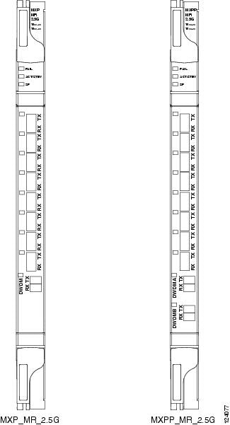
Figure 2. MXP_MR_2.5G and MXPP_MR_2.5G Faceplates

For information about safety labels for the cards, see the "Class 1M Laser Product Cards" section.

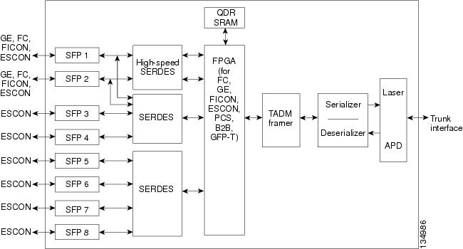
The card has eight SFP client interfaces. Ports 1 and 2 can be used for GE, FC, FICON, or ESCON. Ports 3 through 8 are used for ESCON client interfaces. There are two SERDES blocks dedicated to the high-speed interfaces (GE, FC, FICON, and ESCON) and two SERDES blocks for the ESCON interfaces. A FPGA is provided to support different configurations for different modes of operation. This FPGA has a Universal Test and Operations Physical Interface for ATM (UTOPIA) interface. A transceiver add/drop multiplexer (TADM) chip supports framing. Finally, the output signal is serialized and connected to the trunk front end with a direct modulation laser. The trunk receive signal is converted into an electrical signal with an avalanche photodiode (APD), is deserialized, and is then sent to the TADM framer and FPGA.

The MXPP_MR_2.5G is the same, except a 50/50 splitter divides the power at the trunk interface. In the receive direction, there are two APDs, two SERDES blocks, and two TADM framers. This is necessary to monitor both the working and protect paths. A switch selects one of the two paths to connect to the client interface.

Figure 3. MXP_MR_2.5G and MXPP_MR_2.5G Block Diagram

Caution


You must use a 20-dB fiber attenuator (15 to 25 dB) when working with the MXP_MR_2.5G and MXPP_MR_2.5G cards in a loopback configuration on the trunk port. Do not use direct fiber loopbacks with the MXP_MR_2.5G and MXPP_MR_2.5G cards. Using direct fiber loopbacks causes irreparable damage to the MXP_MR_2.5G and MXPP_MR_2.5G cards.


MXP_MR_2.5G and MXPP_MR_2.5G Functions

The following functions of the MXP_MR_2.5G and MXPP_MR_2.5G cards are explained in the "Card Features" chapter:
  • Performance Monitoring

  • Distance Extension

  • Slot Compatibility

  • Interoperability with Cisco MDS Switches

  • Client and Trunk Ports

  • Automatic Laser Shutdown

  • Card level indicators

  • Port level indicator

MXP_MR_10DME_C and MXP_MR_10DME_L Cards

The MXP_MR_10DME_C and MXP_MR_10DME_L cards aggregate a mix of client SAN service client inputs (GE, FICON, and Fibre Channel) into one 10.0 Gbps STM-64/OC-192 DWDM signal on the trunk side. It provides one long-reach STM-64/OC-192 port per card and is compliant with Telcordia GR-253-CORE and ITU-T G.957.

The cards support aggregation of the following signal types:

  • 1-Gigabit Fibre Channel

  • 2-Gigabit Fibre Channel

  • 4-Gigabit Fibre Channel

  • 1-Gigabit Ethernet

  • 1-Gigabit ISC-Compatible (ISC-1)

  • 2-Gigabit ISC-Peer (ISC-3)


    Note


    On the card faceplates, the MXP_MR_10DME_C and MXP_MR_10DME_L cards are displayed as 10DME_C and 10DME_L, respectively.


    Caution


    The card can be damaged by dropping it. Handle it safely.


    Note


    Because the client payload cannot oversubscribe the trunk, a mix of client signals can be accepted, up to a maximum limit of 10 Gbps.


    The MXP_MR_10DME_C card can be installed in Slots 2 to 7 in Cisco NCS 2015 chassis. This card upgrades to a new bootcode automatically when it is installed between slots 2 and 7. After the bootcode upgrade, the card can be installed in Slots 2 to 16 of the Cisco NCS 2015 chassis.


    Note


    The MXP_MR_10DME_C and MXP_MR_10DME_L cards are not compatible with the MXP_2.5G_10G card, which does not support transparent termination mode.


The MXP_MR_10DME_C card features a tunable 1550-nm C-band laser on the trunk port. The laser is tunable across 82 wavelengths on the ITU grid with 50-GHz spacing between wavelengths. The MXP_MR_10DME_L features a tunable 1580-nm L-band laser on the trunk port. The laser is tunable across 80 wavelengths on the ITU grid, also with 50-GHz spacing. Each card supports eight SFP based client ports and one trunk port. The cards uses dual LC connectors on the trunk side and use SFP modules on the client side for optical cable termination. The SFP pluggable modules are SR or IR and support an LC fiber connector.

The current version of the GFP-T G.7041 supports transparent mapping of 8B/10B block-coded protocols, including Gigabit Ethernet, Fibre Channel, ISC, and FICON.

Table 19. MXP_MR_10DME_C and MXP_MR_10DME_L Client Interface Data Rates and Encapsulation

Client Interface

Input Data Rate

GFP-T G.7041 Encapsulation

2G FC

2.125 Gbps

Yes

1G FC

1.06 Gbps

Yes

2G FICON/2G ISC-Compatible (ISC-1)/ 2G ISC-Peer (ISC-3)

2.125 Gbps

Yes

1G FICON/1G ISC-Compatible (ISC-1)/ 1G ISC-Peer (ISC-3)

1.06 Gbps

Yes

Gigabit Ethernet

1.25 Gbps

Yes

There are two FPGAs on each MXP_MR_10DME_C and MXP_MR_10DME_L, and a group of four ports is mapped to each FPGA. Group 1 consists of Ports 1 through 4, and Group 2 consists of Ports 5 through 8. The following table shows some of the mix and match possibilities on the various client data rates for Ports 1 through 4, and Ports 5 through 8. An X indicates that the data rate is supported in that port.

Table 20. Supported Client Data Rates for Ports 1 through 4 and Ports 5 through 8

Port (Group 1)

Port (Group 2)

Gigabit Ethernet

1G FC

2G FC

4G FC

1

5

X

X

X

X

2

6

X

X

3

7

X

X

X

4

8

X

X

GFP-T PM is available through RMON and trunk PM is managed according to Telcordia GR-253-CORE and ITU G.783/826. Client PM is achieved through RMON for FC and GE.

A buffer-to-buffer credit management scheme provides FC flow control. With this feature enabled, a port indicates the number of frames that can be sent to it (its buffer credit), before the sender is required to stop transmitting and wait for the receipt of a “ready” indication The MXP_MR_10DME_C and MXP_MR_10DME_L cards support FC credit-based flow control with a buffer-to-buffer credit extension of up to 1600 km (994.1 miles) for 1G FC, up to 800 km (497.1 miles) for 2G FC, or up to 400 km (248.5 miles) for 4G FC. The feature can be enabled or disabled.

The MXP_MR_10DME_C and MXP_MR_10DME_L cards feature a 1550-nm laser for the trunk/line port and a 1310-nm or 850-nm laser (depending on the SFP) for the client ports. The cards contains eight 12.5 degree downward tilt SFP modules for the client interfaces. For optical termination, each SFP uses two LC connectors, which are labeled TX and RX on the faceplate. The trunk port is a dual-LC connector with a 45 degree downward angle.

The throughput of the MXP_MR_10DME_C and MXP_MR_10DME_L cards is affected by the following parameters:

  • Distance extension—If distance extension is enabled on the card, it provides more throughput but more latency. If distance extension is disabled on the card, the buffer to buffer credits on the storage switch affects the throughput; higher the buffer to buffer credits higher is the throughput.


    Note


    For each link to operate at the maximum throughput, it requires a minimum number of buffer credits to be available on the devices which the link connects to. The number of buffer credits required is a function of the distance between the storage switch extension ports and the link bandwidth, that is, 1G, 2G, or 4G. These buffer credits are provided by either the storage switch (if distance extension is disabled) or by both the storage switch and the card (if distance extension is enabled).


  • Forward Error Correction (FEC)—If Enhanced FEC (E-FEC) is enabled on the trunk port of the card, the throughout is significantly reduced in comparison to standard FEC being set on the trunk port.


    Note


    If distance extension is enabled on the card, the FEC status does not usually affect the throughput of the card.


  • Payload size—The throughput of the card decreases with decrease in payload size.

The resultant throughput of the card is usually the combined effect of the above parameters.

Key Features

The MXP_MR_10DME_C and MXP_MR_10DME_L cards have the following high-level features:

  • Onboard E-FEC processor: The processor supports both standard RS (specified in ITU-T G.709) and E-FEC, which allows an improved gain on trunk interfaces with a resultant extension of the transmission range on these interfaces. The E-FEC functionality increases the correction capability of the transponder to improve performance, allowing operation at a lower OSNR compared to the standard RS (255,239) correction algorithm. A new BCH algorithm implemented in E-FEC allows recovery of an input BER up to 1E-3.

  • Pluggable client interface optic modules: The MXP_MR_10DME_C and MXP_MR_10DME_L cards have modular interfaces. Two types of optics modules can be plugged into the card. These include an OC-48/STM 16 SR-1 interface with a 7-km (4.3-mile) nominal range (for short range and intra-office applications) and an IR-1 interface with a range up to 40 km (24.9 miles). SR-1 is defined in Telcordia GR-253-CORE and in I-16 (ITU-T G.957). IR-1 is defined in Telcordia GR-253-CORE and in S-16-1 (ITU-T G.957).

  • Y-cable protection: Supports Y-cable protection between the same card type only, on ports with the same port number and signal rate. See the "Y-Cable Protection Availability on TXP, MXP, and Xponder Cards” section for more detailed information.

  • High level provisioning support: The cards are initially provisioned using Cisco TransportPlanner software. Subsequently, the card can be monitored and provisioned using CTC software.

  • ALS: A safety mechanism used in the event of a fiber cut. For details regarding ALS provisioning for the MXP_MR_10DME_C and MXP_MR_10DME_L cards, see the “NTP-G162 Change the ALS Maintenance Settings” section.

  • Link monitoring and management: The cards use standard OC-48 OH bytes to monitor and manage incoming interfaces. The cards pass the incoming SDH/SONET data stream and its OH bytes transparently.

  • Control of layered SONET/SDH transport overhead: The cards are provisionable to terminate regenerator section overhead. This is used to eliminate forwarding of unneeded layer overhead. It can help reduce the number of alarms and help isolate faults in the network.

  • Automatic timing source synchronization: The MXP_MR_10DME_C and MXP_MR_10DME_L cards normally synchronize from the control card. If for some reason, such as maintenance or upgrade activity, the control card is not available, the cards automatically synchronize to one of the input client interface clocks.


    Note


    MXP_MR_10DME_C and MXP_MR_10DME_L cards cannot be used for line timing.


  • Configurable squelching policy: The cards can be configured to squelch the client interface output if there is LOS at the DWDM receiver or if there is a remote fault. In the event of a remote fault, the card manages MS-AIS insertion.

  • The cards are tunable across the full C band (MXP_MR_10DME_C) or full L band (MXP_MR_10DME_L), thus eliminating the need to use different versions of each card to provide tunability across specific wavelengths in a band.

  • You can provision a string (port name) for each fiber channel/FICON interface on the MXP_MR_10DME_C and MXP_MR_10DME_L cards, which allows the MDS Fabric Manager to create a link association between that SAN port and a SAN port on a Cisco MDS 9000 switch.

  • From Software Release 9.0, the fast switch feature of MXP_MR_10DME_C and MXP_MR_10DME_L cards along with the buffer-to-buffer credit recovery feature of MDS switches, prevents reinitialization of ISL links during Y-cable switchovers.

For a detailed list of the supported pluggables, see, http://www.cisco.com/c/en/us/td/docs/optical/spares/gbic/guides/b_ncs_pluggables.html

MXP_MR_10DME_C and MXP_MR_10DME_L Functions

The following functions of the MXP_MR_10DME_C and MXP_MR_10DME_L cards are explained in the "Card Features" chapter:

  • Card level indicators

  • Port level indicators

Wavelength Identification

The card uses trunk lasers that are wavelocked, which allows the trunk transmitter to operate on the ITU grid effectively. Both the MXP_MR_10DME_C and MXP_MR_10DME_L cards implement the UT2 module. The MXP_MR_10DME_C card uses a C-band version of the UT2 and the MXP_MR_10DME_L card uses an L-band version.

The MXP_MR_10DME_C card is tunable over 82 wavelengths in the C band at 50-GHz spacing on the ITU grid.

Table 21. MXP_MR_10DME_C Trunk Wavelengths

Channel Number

Frequency (THz)

Wavelength (nm)

Channel Number

Frequency (THz)

Wavelength (nm)

1

196.00

1529.55

42

193.95

1545.72

2

195.95

1529.94

43

193.90

1546.119

3

195.90

1530.334

44

193.85

1546.518

4

195.85

1530.725

45

193.80

1546.917

5

195.80

1531.116

46

193.75

1547.316

6

195.75

1531.507

47

193.70

1547.715

7

195.70

1531.898

48

193.65

1548.115

8

195.65

1532.290

49

193.60

1548.515

9

195.60

1532.681

50

193.55

1548.915

10

195.55

1533.073

51

193.50

1549.32

11

195.50

1533.47

52

193.45

1549.71

12

195.45

1533.86

53

193.40

1550.116

13

195.40

1534.250

54

193.35

1550.517

14

195.35

1534.643

55

193.30

1550.918

15

195.30

1535.036

56

193.25

1551.319

16

195.25

1535.429

57

193.20

1551.721

17

195.20

1535.822

58

193.15

1552.122

18

195.15

1536.216

59

193.10

1552.524

19

195.10

1536.609

60

193.05

1552.926

20

195.05

1537.003

61

193.00

1553.33

21

195.00

1537.40

62

192.95

1553.73

22

194.95

1537.79

63

192.90

1554.134

23

194.90

1538.186

64

192.85

1554.537

24

194.85

1538.581

65

192.80

1554.940

25

194.80

1538.976

66

192.75

1555.343

26

194.75

1539.371

67

192.70

1555.747

27

194.70

1539.766

68

192.65

1556.151

28

194.65

1540.162

69

192.60

1556.555

29

194.60

1540.557

70

192.55

1556.959

30

194.55

1540.953

71

192.50

1557.36

31

194.50

1541.35

72

192.45

1557.77

32

194.45

1541.75

73

192.40

1558.173

33

194.40

1542.142

74

192.35

1558.578

34

194.35

1542.539

75

192.30

1558.983

35

194.30

1542.936

76

192.25

1559.389

36

194.25

1543.333

77

192.20

1559.794

37

194.20

1543.730

78

192.15

1560.200

38

194.15

1544.128

79

192.10

1560.606

39

194.10

1544.526

80

192.05

1561.013

40

194.05

1544.924

81

192.00

1561.42

41

194.00

1545.32

82

191.95

1561.83

The MXP_MR_10DME_L card is fully tunable over 80 wavelengths in the L band at 50-GHz spacing on the ITU grid.

Table 22. MXP_MR_10DME_L Trunk Wavelengths

Channel Number

Frequency (THz)

Wavelength (nm)

Channel Number

Frequency (THz)

Wavelength (nm)

1

190.85

1570.83

41

188.85

1587.46

2

190.8

1571.24

42

188.8

1587.88

3

190.75

1571.65

43

188.75

1588.30

4

190.7

1572.06

44

188.7

1588.73

5

190.65

1572.48

45

188.65

1589.15

6

190.6

1572.89

46

188.6

1589.57

7

190.55

1573.30

47

188.55

1589.99

8

190.5

1573.71

48

188.5

1590.41

9

190.45

1574.13

49

188.45

1590.83

10

190.4

1574.54

50

188.4

1591.26

11

190.35

1574.95

51

188.35

1591.68

12

190.3

1575.37

52

188.3

1592.10

13

190.25

1575.78

53

188.25

1592.52

14

190.2

1576.20

54

188.2

1592.95

15

190.15

1576.61

55

188.15

1593.37

16

190.1

1577.03

56

188.1

1593.79

17

190.05

1577.44

57

188.05

1594.22

18

190

1577.86

58

188

1594.64

19

189.95

1578.27

59

187.95

1595.06

20

189.9

1578.69

60

187.9

1595.49

21

189.85

1579.10

61

187.85

1595.91

22

189.8

1579.52

62

187.8

1596.34

23

189.75

1579.93

63

187.75

1596.76

24

189.7

1580.35

64

187.7

1597.19

25

189.65

1580.77

65

187.65

1597.62

26

189.6

1581.18

66

187.6

1598.04

27

189.55

1581.60

67

187.55

1598.47

28

189.5

1582.02

68

187.5

1598.89

29

189.45

1582.44

69

187.45

1599.32

30

189.4

1582.85

70

187.4

1599.75

31

189.35

1583.27

71

187.35

1600.17

32

189.3

1583.69

72

187.3

1600.60

33

189.25

1584.11

73

187.25

1601.03

34

189.2

1584.53

74

187.2

1601.46

35

189.15

1584.95

75

187.15

1601.88

36

189.1

1585.36

76

187.1

1602.31

37

189.05

1585.78

77

187.05

1602.74

38

189

1586.20

78

187

1603.17

39

188.95

1586.62

79

186.95

1603.60

40

188.9

1587.04

80

186.9

1604.03

For more information about the MXP_MR_10DME_C and MXP_MR_10DME_L cards, see http://www.cisco.com/en/US/prod/collateral/optical/ps5724/ps2006/ps5320/product_data_sheet0900aecd803fc51a.html.

40G-MXP-C, 40E-MXP-C, and 40ME-MXP-C Cards

The 40G-MXP-C, 40E-MXP-C, and 40ME-MXP-C cards aggregate a variety of client service inputs (Gigabit Ethernet, Fibre Channel, OTU2, OTU2e, and OC-192) into a single 40-Gbps OTU3/OTU3e signal on the trunk side.


Note


In CTC, the 40E-MXP-C and 40ME-MXP-C card is displayed with the same card name, 40E-MXP-C.


The 40G-MXP-C, 40E-MXP-C, and 40ME-MXP-C cards support aggregation of the following signals:

  • With overclock enabled on the trunk port:

    • OC-192/STM-64 (only on 40E-MXP-C and 40ME-MXP-C cards)

    • 10 Gigabit Fibre Channel

    • OTU2e

    • 10 Gigabit Ethernet LAN-Phy (CBR mapping) (only on 40E-MXP-C and 40ME-MXP-C cards)

  • With overclock disabled on the trunk port:

    • 8 Gigabit Fibre Channel

    • 10 GigabitEthernet LAN-Phy (GFP framing)

    • 10 GigabitEthernet LAN-Phy (WIS framing)

    • OC-192/STM-64

    • OTU2


      Caution


      Handle the card with care. Dropping or misuse of the card could result in permanent damage.


You can install and provision the 40G-MXP-C, cards in a linear configuration in:

  • Slot 2 in Cisco NCS 2002 chassis

  • Slots 2 to 15 in Cisco NCS 2015 chassis (for 40E-MXP-C card)

The client ports of the 40G-MXP-C, 40E-MXP-C, and 40ME-MXP-C cards interoperates with all the existing TXP/MXP (OTU2 trunk) cards.

The auto negotiation is not supported on the 40G-MXP-C, 40E-MXP-C, and 40ME-MXP-C cards in 8G FC client mode. Hence, during interoperation, the auto negotiation of the 8G-FC client port of the other device connected to 8G-FC client port on 40G-MXP-C, 40E-MXP-C, or 40ME-MXP-C card must be set to Fixed/Disabled.

The client port of 40G-MXP-C, 40E-MXP-C, and 40ME-MXP-C cards do not interoperate with OTU2_XP card when the signal rate is OTU1e (11.049 Gbps) and the “No Fixed Stuff” option is enabled on the trunk port of OTU2_XP card.

For OTU2 and OTU2e client protocols, Enhanced FEC (EFEC) is not supported on Port 1 of the 40G-MXP-C, 40E-MXP-C, and 40ME-MXP-C cards.

Table 23. Client Interface Data Rates for 40G-MXP-C, 40E-MXP-C and 40ME-MXP-C Cards

40G-MXP-C, 40E-MXP-C and 40ME-MXP-C Client Port

FEC Configuration Supported on OTU2/OTU2e Client Protocol

Port 1

Only Standard FEC

Port 2

Standard and Enhanced FEC

Port 3

Standard and Enhanced FEC

Port 4

Standard and Enhanced FEC

When setting up the card for the first time, or when the card comes up after clearing the LOS-P condition due to fiber cut, the trunk port of the 40G-MXP-C card takes about 6 minutes to lock a signal. The trunk port of the 40G-MXP-C card raises an OTUK-LOF alarm when the card is comes up. The alarm clears when the trunk port locks the signal.

When a protection switch occurs on the 40E-MXP-C and 40ME-MXP-C cards, the recovery from PSM protection switch takes about 3 to 4 minutes.

Key Features

The 40G-MXP-C, 40E-MXP-C, and 40ME-MXP-C cards provides the following key features:

  • The 40G-MXP-C card uses the RZ-DQPSK 40G modulation format.

  • The 40E-MXP-C and 40ME-MXP-C cards uses the CP-DQPSK modulation format.

  • Onboard E-FEC processor—The E-FEC functionality improves the correction capability of the transponder to improve performance, allowing operation at a lower OSNR compared to the standard RS (239,255) correction algorithm. A new BCH algorithm implemented (according to G.975.1 I.7) in E-FEC allows recovery of an input BER up to 1E-3. The 40G-MXP-C, 40E-MXP-C, and 40ME-MXP-C cards support both the standard RS (specified in ITU-T G.709) and E-FEC standard, which allows an improved gain on trunk interfaces with a resultant extension of the transmission range on these interfaces.

  • Y-cable protection—Supports Y-cable protection only between the same card type on ports with the same port number and signal rate. For more information on Y-cable protection, see the "Y-Cable Protection Availability on TXP, MXP, and Xponder Cards" section.


    Note


    Y-cable cannot be created on a 10 GE port when WIS framing is enabled on the 40G-MXP-C, 40E-MXP-C, and 40ME-MXP-C cards.


  • Unidirectional regeneration—The 40G-MXP-C, 40E-MXP-C, and 40ME-MXP-C cards supports unidirectional regeneration configuration. Each 40G-MXP-C, 40E-MXP-C, and 40ME-MXP-C card in the configuration regenerates the signal received from another 40G-MXP-C, 40E-MXP-C, and 40ME-MXP-C card in one direction.


    Note


    When you configure the 40G-MXP-C, 40E-MXP-C, and 40ME-MXP-C cards in the Unidirectional Regen mode, ensure that the payload is not configured on the pluggable port modules of the 40G-MXP-C, 40E-MXP-C, and 40ME-MXP-C card.


    Figure 4. 40G-MXP-C, 40E-MXP-C, and 40ME-MXP-C Cards in Unidirectional Regeneration Configuration
  • High level provisioning support—The cards are initially provisioned using Cisco Transport Planner software. Subsequently, the card can be monitored and provisioned using CTC software.

  • Automatic Laser Shutdown (ALS)—A safety mechanism, Automatic Laser Shutdown (ALS), is used in the event of a fiber cut. The Auto Restart ALS option is supported only for OC-192/STM-64 and OTU2 payloads. The Manual Restart ALS option is supported for all payloads. For more information on provisioning ALS for the 40G-MXP-C, 40E-MXP-C, and 40ME-MXP-C cards, see the “NTP-G162 Change the ALS Maintenance Settings” section.

  • Control of layered SONET/SDH transport overhead—The cards are provisionable to terminate regenerator section overhead. This is used to eliminate forwarding of unneeded layer overhead. It can help reduce the number of alarms and help isolate faults in the network.

  • Automatic timing source synchronization—The 40G-MXP-C, 40E-MXP-C, and 40ME-MXP-C cards synchronize to the card cards. Because of a maintenance or upgrade activity, if the control cards are not available, the cards automatically synchronize to one of the input client interface clocks.

  • Squelching policy—The cards are set to squelch the client interface output if there is LOS at the DWDM receiver, or if there is a remote fault. In the event of a remote fault, the card manages MS-AIS insertion.

  • The 40G-MXP-C, 40E-MXP-C, and 40ME-MXP-C cards are tunable across the full C-band wavelength.

For a detailed list of the supported pluggables, see, http://www.cisco.com/c/en/us/td/docs/optical/spares/gbic/guides/b_ncs_pluggables.html

Wavelength Identification

The 40G-MXP-C, 40E-MXP-C, and 40ME-MXP-C cards use trunk lasers that are wavelocked, which allows the trunk transmitter to operate on the ITU grid effectively. These cards implement the UT2 module; they use a C-band version of the UT2. The laser is tunable over 82 wavelengths in the C-band at 50-GHz spacing on the ITU grid.

Table 24. 40G-MXP-C, 40E-MXP-C, and 40ME-MXP-C Trunk Wavelengths

Channel Number

Frequency (THz)

Wavelength (nm)

Channel Number

Frequency (THz)

Wavelength (nm)

1

196.00

1529.55

42

193.95

1545.72

2

195.95

1529.94

43

193.90

1546.119

3

195.90

1530.334

44

193.85

1546.518

4

195.85

1530.725

45

193.80

1546.917

5

195.80

1531.116

46

193.75

1547.316

6

195.75

1531.507

47

193.70

1547.715

7

195.70

1531.898

48

193.65

1548.115

8

195.65

1532.290

49

193.60

1548.515

9

195.60

1532.681

50

193.55

1548.915

10

195.55

1533.073

51

193.50

1549.32

11

195.50

1533.47

52

193.45

1549.71

12

195.45

1533.86

53

193.40

1550.116

13

195.40

1534.250

54

193.35

1550.517

14

195.35

1534.643

55

193.30

1550.918

15

195.30

1535.036

56

193.25

1551.319

16

195.25

1535.429

57

193.20

1551.721

17

195.20

1535.822

58

193.15

1552.122

18

195.15

1536.216

59

193.10

1552.524

19

195.10

1536.609

60

193.05

1552.926

20

195.05

1537.003

61

193.00

1553.33

21

195.00

1537.40

62

192.95

1553.73

22

194.95

1537.79

63

192.90

1554.134

23

194.90

1538.186

64

192.85

1554.537

24

194.85

1538.581

65

192.80

1554.940

25

194.80

1538.976

66

192.75

1555.343

26

194.75

1539.371

67

192.70

1555.747

27

194.70

1539.766

68

192.65

1556.151

28

194.65

1540.162

69

192.60

1556.555

29

194.60

1540.557

70

192.55

1556.959

30

194.55

1540.953

71

192.50

1557.36

31

194.50

1541.35

72

192.45

1557.77

32

194.45

1541.75

73

192.40

1558.173

33

194.40

1542.142

74

192.35

1558.578

34

194.35

1542.539

75

192.30

1558.983

35

194.30

1542.936

76

192.25

1559.389

36

194.25

1543.333

77

192.20

1559.794

37

194.20

1543.730

78

192.15

1560.200

38

194.15

1544.128

79

192.10

1560.606

39

194.10

1544.526

80

192.05

1561.013

40

194.05

1544.924

81

192.00

1561.42

41

194.00

1545.32

82

191.95

1561.83

For more information on 40G-MXP-C card, see http://www.cisco.com/en/US/prod/collateral/optical/ps5724/ps2006/datasheet_c78-598898.html.

For more information on 40E-MXP-C and 40ME-MXP-C cards, see http://www.cisco.com/en/US/prod/collateral/optical/ps5724/ps2006/data_sheet_c78-606950.html.

GE_XP, 10GE_XP, GE_XPE, and 10GE_XPE Cards


Note


GE_XPE card is the enhanced version of the GE_XP card and 10GE_XPE card is the enhanced version of the 10GE_XP card.


The cards aggregate Ethernet packets received on the client ports for transport on C-band trunk ports that operate on a 100-GHz grid. The trunk ports operate with ITU-T G.709 framing and either FEC or E-FEC. The GE_XP and 10GE_XP cards are designed for bulk point-to-point transport over 10GE LAN PHY wavelengths for Video-on-Demand (VOD), or broadcast video across protected 10GE LAN PHY wavelengths. The GE_XPE and 10GE_XPE cards are designed for bulk GE_XPE or 10GE_XPE point-to-point, point-to-multipoint, multipoint-to-multipoint transport over 10GE LAN PHY wavelengths for Video-on-Demand (VOD), or broadcast video across protected 10GE LAN PHY wavelengths.


Note


When all the cards in the chassis are simultaneously reset by the user, the GE_XP and 10GE_XP cards undergo a hard reset instead of a soft reset. This causes traffic loss for traffic going through these cards.


You can install and provision the GE_XP, and GE_XPE cards in a linear configuration in:

  • Slot 2 in Cisco NCS 2002 chassis

  • Slots 2 to 6 in Cisco NCS 2006 chassis

  • Slots 2 to 7 in Cisco NCS 2015 chassis. These cards upgrade to a new bootcode automatically when they are installed between slots 2 and 7.

    After the bootcode upgrade, the cards can be installed in Slots from 2 to 16 in Cisco NCS 2015 chassis.

The RAD pluggables (ONS-SC-E3-T3-PW= and ONS-SC-E1-T1-PW=) do not support:

  • No loopbacks (Terminal or Facility)

  • RAI (Remote Alarm Indication) alarm

  • AIS and LOS alarm


    Caution


GE_XP, 10GE_XP, GE_XPE, and 10GE_XPE cards can be provisioned to perform different Gigabit Ethernet transport roles. All the cards can work as Layer 2 switches. However, the 10GE_XP and 10GE_XPE cards can also perform as a 10 Gigabit Ethernet transponders (10GE TXP mode), and the GE_XP and GE_XPE can perform as a 10 Gigabit Ethernet or 20 Gigabit Ethernet muxponders (10GE MXP or 20GE MXP mode).


Note


Changing the GE_XP, 10GE_XP, GE_XPE, or 10GE_XPE card mode requires the ports to be in a OOS-DSBL (ANSI) or Locked, disabled (ETSI) service state. In addition, no circuits can be provisioned on the cards when the mode is being changed.


Table 25. GE_XP, 10GE_XP, GE_XPE, and 10GE_XPECard Modes

Card Mode

Cards

Description

Layer 2 Ethernet switch

GE_XP

10GE_XP

GE_XPE

10GE_XPE

Provides capability to switch between any two ports irrespective of client or trunk port. Supported Ethernet protocols and services include 1+1 protection, QoS (Quality of Service), CoS (Class of Service), QinQ, MAC learning, MAC address retrieval, service provider VLANs (SVLANs), IGMP snooping and Multicast VLAN Registration (MVR), link integrity, and other Ethernet switch services.

10GE TXP

10GE_XP

10GE_XPE

Provides a point-to-point application in which each 10 Gigabit Ethernet client port is mapped to a 10 Gigabit Ethernet trunk port.

10GE MXP

20GE MXP

GE_XP

GE_XPE

Provides the ability to multiplex the twenty Gigabit Ethernet client ports on the card to one or both of its 10 Gigabit Ethernet trunk ports. The card can be provisioned as a single MXP with twenty Gigabit Ethernet client ports mapped to one trunk port (Port 21) or as two MXPs with ten Gigabit Ethernet client ports mapped to a trunk port (Ports 1 to 10 mapped to Port 21, and Ports 11-20 mapped to Port 22).

Key Features

The GE_XP, 10GE_XP, GE_XPE, and 10GE_XPE cards have the following high-level features:

  • Link Aggregation Control Protocol (LACP) that allows you to bundle several physical ports together to form a single logical channel.

  • Ethernet Connectivity Fault Management (CFM) protocol that facilitates proactive connectivity monitoring, fault verification, and fault isolation.

  • Ethernet Operations, Administration, and Maintenance (OAM) protocol that facilitates link monitoring, remote failure indication, and remote loopback.

  • Resilient Ethernet Protocol (REP) that controls network loops, handles link failures, and improves convergence time.

  • Configurable service VLANs (SVLANs) and customer VLANs (CVLANs).

  • Ingress rate limiting that can be applied on both SVLANs and CVLANs. You can create SVLAN and CVLAN profiles and can associate a SVLAN profile to both UNI and NNI ports; however, you can associate a CVLAN profile only to UNI ports.

  • CVLAN rate limiting that is supported for QinQ service in selective add mode.

  • Differentiated Services Code Point (DSCP) to class of service (CoS) mapping that you can configure for each port. You can configure the CoS of the outer VLAN based on the incoming DSCP bits. This feature is supported only on GE_XPE and 10GE_XPE cards.

  • Ports, in Layer 2 switch mode, can be provisioned as network-to-network interfaces (NNIs) or user-network interfaces (UNIs) to facilitate service provider to customer traffic management.

  • Broadcast drop-and-continue capability for VOD and broadcast video applications.

  • Gigabit Ethernet MXP, TXP, and Layer 2 switch capability.

  • For more information on FELC, see the"Far-End Laser Control" section.

  • Layer 2 switch mode that provides VLAN translation, QinQ, ingress CoS, egress QoS, Fast Ethernet protection switching, and other Layer 2 Ethernet services.

  • Interoperable with TXP_MR_10E and TXP_MR_10E_C cards. Also interoperable with Cisco Catalyst 6500 and Cisco 7600 series Gigabit Ethernet, 10 GE interfaces and CRS-1 10GE interfaces.

  • The GE_XP and GE_XPE cards have twenty Gigabit Ethernet client ports and two 10 Gigabit Ethernet trunk ports. The 10GE_XP and 10GE_XPE cards have two 10 Gigabit Ethernet client ports and two 10 Gigabit Ethernet trunk ports. The client Gigabit Ethernet signals are mapped into an ITU-T G.709 OTU2 signal using standard ITU-T G.709 multiplexing when configured in one of the MXP modes (10GE MXP or 20GE MXP).

  • ITU-T G.709 framing with standard Reed-SoloMon (RS) (255,239) FEC. Performance monitoring and ITU-T G.709 Optical Data Unit (ODU) synchronous and asynchronous mapping. E-FEC with ITU-T G.709 ODU and 2.7 Gbps with greater than 8 dB coding gain.

  • IEEE 802.3 frame format that is supported for 10 Gigabit Ethernet interfaces. The minimum frame size is 64 bytes. The maximum frame size is user-provisionable.

  • MAC learning capability in Layer 2 switch mode.

  • MAC address retrieval in cards provisioned in the L2-over-DWDM mode.

  • When a port is in UNI mode, tagging can be configured as transparent or selective. In transparent mode, only SVLANs in the VLAN database of the node can be configured. In selective mode, a CVLAN- to-SVLAN relationship can be defined.

  • Layer 2 VLAN port mapping that allows the cards to be configured as multiple Gigabit Ethernet TXPs and MXPs.

  • Y-cable protection is configurable in TXP and MXP modes.

  • Two protection schemes are available in Layer 2 mode. They are:

    • 1+1 protection—Protection scheme to address card, port, or shelf failures for client ports.

    • Fast Automatic Protection—Protection scheme to address card, port, or shelf failures for trunk ports.

  • End-to-end Ethernet link integrity.

  • Pluggable client interface optic modules (SFPs and XFPs)—Client ports support tri-rate SX, LX, and ZX SFPs, and 10-Gbps SR1 XFPs.

  • Pluggable trunk interface optic modules; trunk ports support the DWDM XFP.

  • Internet Group Management Protocol (IGMP) snooping that restricts the flooding of multicast traffic by forwarding multicast traffic to those interfaces where a multicast device is present.

  • Multicast VLAN Registration (MVR) for applications using wide-scale deployment of multicast traffic across an Ethernet ring-based service provider network.

  • Ingress CoS that assigns a CoS value to the port from 0 (highest) to 7 (lowest) and accepts CoS of incoming frames.

  • Egress QoS that defines the QoS capabilities for the egress port.

  • MAC address learning that facilitates switch processing.

  • Storm Control that limits the number of packets passing through a port. You can define the maximum number of packets allowed per second for the following types of traffic: Broadcast, Multicast, and Unicast. The threshold for each type of traffic is independent and the maximum number of packets allowed per second for each type of traffic is 16777215.

For a detailed list of the supported pluggables, see, http://www.cisco.com/c/en/us/td/docs/optical/spares/gbic/guides/b_ncs_pluggables.html

Protocol Compatibility list

Table 26. Protocol Compatibility List for GE_XP, 10GE_XP, GE_XPE, and 10GE_XPE Cards
Protocol LI 1+1 FAPS IGMP REP LACP CFM EFM

LI

No

Yes

Yes

No

No

Yes

No

1+1

No

Yes

Yes

No

No

Yes

No

FAPS

Yes

Yes

Yes

No

No

Yes

No

IGMP

Yes

Yes

Yes

Yes

No

Yes

No

REP

No

No

No

Yes

No

Yes

No

LACP

No

No

No

No

No

No

No

CFM

Yes

Yes

Yes

Yes

Yes

No

No

EFM

No

No

No

No

No

No

No

The 10GE_XP and 10GE_XPE card trunk ports are displayed as follows:

  • Trunk 1 and Trunk 2 on the faceplate

  • 3-1 and 4-1 on CTC

  • 3 (Trunk) and 4 (Trunk) on the Optics Thresholds table

Client Interface

The client interface is implemented with separately orderable SFP or XFP modules. The client interfaces support the following tri-rate SFPs and XFPs using dual LC connectors and multimode fiber:

  • SFP - GE/1G-FC/2G-FC - 850 nm - MM - LC (PID ONS-SE-G2F-SX)

  • SFP - GE/1G-FC/2G-FC 1300 nm - SM - LC (PID ONS-SE-G2F-LX)

  • SFP - GE/1G-FC/2G-FC 1300 nm - SM - LC (PID ONS-SE-G2F-ZX)

  • SFP - 10/100/1000Base-T - Copper (PID ONS-SE-ZE-EL) Intra office up to 100;
Cable: RJ45 STP CAT5, CAT5E, and CAT6

  • SFP - 1000Base BX D/Gigabit Ethernet 1550 nm - SM - LC (PID ONS-SE-GE-BXD)

  • SFP - 1000Base BX U/Gigabit Ethernet 1550 nm - SM - LC (PID ONS-SE-GE-BXU)

  • SFP - Fast Ethernet 1310 nm - SM - LC (PID ONS-SI-100-LX10)

  • SFP - Fast Ethernet 1310 nm - MM - LC (PID ONS-SI-100-FX)

  • SFP - Fast Ethernet over DS1/E1 - SM - LC (PID ONS-SC-EOP1)

  • SFP - Fast Ethernet over DS3/E3 - SM - LC (PID ONS-SC-EOP3)

  • SFP - E1/DS1 over Fast Ethernet - SM - LC (PID ONS-SC-E1-T1-PW)

  • SFP - E3/DS3 PDH over Fast Ethernet - SM - LC (PID ONS-SC-E3-T3-PW)

    Figure 5. Recommended Topology for Using ONS-SC-E1-T1-PW and ONS -SC-E3-T3-PW SFPs

The client interfaces support the following dual-rate XFP using dual LC connectors and single-mode fiber:

  • XFP - OC-192/STM-64/10GE/10-FC/OTU2 - 1310 SR - SM LC (PID: ONS-XC-10G-S1)

  • XFP - 10GE - 1550 nm - SM - LC (PID ONS-XC-10G-L2)

  • XFP - 10GE - 1550 nm - SM - LC (PID ONS-XC-10G-C)


    Note


    If ONS-XC-10G-C XFP is used on GE_XP, 10GE_XP, GE_XPE, and 10GE_XPE cards on client port 1, the maximum temperature at which the system qualifies is +45 degree Celsius.


The client interfaces support the following multimode XFP using dual LC connectors and multi-mode fiber:

  • XFP - OC-192/10GFC/10GE - 850 nm MM LC (PID ONS-XC-10G-SR-MM)

DWDM Trunk Interface

The GE_XP, 10GE_XP, GE_XPE, and 10GE_XPE cards have two 10 Gigabit Ethernet trunk ports operating at 10 Gigabit Ethernet (10.3125 Gbps) or 10 Gigabit Ethernet into OTU2 (nonstandard 11.0957 Gbps). The ports are compliant with ITU-T G.707, ITU-T G.709, and Telcordia GR-253-CORE standards. The ports are capable of carrying C-band and L-band wavelengths through insertion of DWDM XFPs. Forty channels are available in the 1550-nm C band 100-GHz ITU grid, and forty channels are available in the L band.

The maximum system reach in filterless applications without the use of optical amplification or regenerators is nominally rated at 23 dB over C-SMF and NZ-DS SMF fibers. This rating is not a product specification, but is given for informational purposes. It is subject to change.

Configuration Management

The GE_XP, 10GE_XP, GE_XPE, and 10GE_XPE cards support the following configuration management parameters:

  • Port name—User-assigned text string.

  • Admin State/Service State—Administrative and service states to manage and view port status.

  • MTU—Provisionable maximum transfer unit (MTU) to set the maximum number of bytes per frames accepted on the port.

  • Mode—Provisional port mode, either Autonegotiation or the port speed.

  • Flow Control—Flow control according to IEEE 802.1x pause frame specification can be enabled or disabled for TX and RX ports.

  • Bandwidth—Provisionable maximum bandwidth allowed for the port.

  • Ingress CoS—Assigns a CoS value to the port from 0 (highest) to 7 (lowest) and accepts CoS of incoming frames.

  • Egress QoS—Defines the QoS capabilities at the egress port.

  • NIM—Defines the port network interface management type based on Metro Ethernet Forum specifications. Ports can be defined as UNI or NNI.

  • MAC Learning—MAC address learning to facilitate switch processing.

  • VLAN tagging provided according to the IEEE 802.1Q standard.


    Note


    When the GE_XP, 10GE_XP, GE_XPE, and 10GE_XPE cards are provisioned in a MXP or TXP mode, only the following parameters are available: Port Name, State, MTU, Mode, Flow control, and Bandwidth.


Security

GE_XP, 10GE_XP, GE_XPE, and 10GE_XPE card ports can be provisioned to block traffic from a user-defined set of MAC addresses. The remaining traffic is normally switched. You can manually specify the set of blocked MAC addresses for each port. Each port of the card can receive traffic from a limited predefined set of MAC addresses. The remaining traffic will be dropped. This capability is a subset of the Cisco IOS “Port Security” feature.

Card Protection

The following card protection schemes are available for the GE_XP, 10GE_XP, GE_XPE, and 10GE_XPE cards.
  • Y-Cable protection

  • 1+1 protection

  • L2 over DWDM protection- Fast Automatic Protection Switch (FAPS)

IGMP Snooping

As networks increase in size, multicast routing becomes critically important as a means to determine which segments require multicast traffic and which do not. IP multicasting allows IP traffic to be propagated from one source to a number of destinations, or from many sources to many destinations. Rather than sending one packet to each destination, one packet is sent to the multicast group identified by a single IP destination group address. GE_XP, 10GE_XP, GE_XPE, and 10GE_XPE cards can learn up to a maximum of 1024 multicast groups. This includes groups on all the VLANs.

Internet Group Management Protocol (IGMP) snooping restricts the flooding of multicast traffic by forwarding multicast traffic to those interfaces where a multicast device is present.

When the GE_XP, 10GE_XP, GE_XPE, or 10GE_XPE card receives an IGMP leave group message from a host, it removes the host port from the multicast forwarding table after generating group specific queries to ensure that no other hosts interested in traffic for the particular group are present on that port. Even in the absence of any “leave” message, the cards have a timeout mechanism to update the group table with the latest information. After a card relays IGMP queries from the multicast router, it deletes entries periodically if it does not receive any IGMP membership reports from the multicast clients.

In a multicast router, general queries are sent on a VLAN when Protocol Independent Multicast (PIM) is enabled on the VLAN. The GE_XP, 10GE_XP, GE_XPE, or 10GE_XPE card forwards queries to all ports belonging to the VLAN. All hosts interested in this multicast traffic send Join requests and are added to the forwarding table entry. The Join requests are forwarded only to router ports. By default, these router ports are learned dynamically. However, they can also be statically configured at the port level in which case the static configuration overrides dynamic learning.

For information about interaction of IGMP with other protocols, see the “Protocol Compatibility list” section on page 11-50.

IGMP Snooping Guidelines and Restrictions

The following guidelines and restrictions apply to IGMP snooping on GE_XP, 10GE_XP, GE_XPE, and 10GE_XPE cards:

  • IGMP snooping V2 is supported as specified in RFC 4541.

  • IGMP snooping V3 is not supported and the packets are flooded in the SVLAN.

  • Layer 2 multicast groups learned through IGMP snooping are dynamic.

  • GE_XP and 10GE_XP cards support IGMP snooping on 128 stacked VLANs and GE_XPE and 10GE_XPE cards support up to 256 stacked VLANs that are enabled.

  • IGMP snooping can be configured per SVLAN or CVLAN. By default, IGMP snooping is disabled on all SVLANs and CVLANs.

  • IGMP snooping on CVLAN is enabled only when:

    • MVR is enabled.

    • UNI ports are in selective add and selective translate modes. For each UNI port, a CVLAN must be specified for which IGMP snooping is to be enabled.

  • IGMP snooping can be enabled only on one CVLAN per port. If you enable IGMP snooping on CVLAN, you cannot enable IGMP snooping on the associated SVLAN and vice versa. The number of VLANs that can be enabled for IGMP snooping cannot exceed 128.

  • When IGMP snooping is enabled on double-tagged packets, CVLAN has to be the same on all ports attached to the same SVLAN.

  • When IGMP snooping is working with the Fast Automatic Protection Switch (FAPS) in a ring-based setup, it is advisable to configure all NNI ports as static router ports. This minimizes the multicast traffic hit when a FAPS switchover occurs.

The following conditions are raised from IGMP snooping at the card:

  • MCAST-MAC-TABLE-FULL—This condition is raised when the multicast table is full and a new join request is received. This table is cleared when at least one entry gets cleared from the multicast table after the alarm is raised.

  • MCAST-MAC-ALIASING—This condition is raised when there are multiple L3 addresses that map to the same L2 address in a VLAN. This is a transient condition.

For more information on severity level of these conditions and procedure to clear these alarms, refer to the Cisco NCS 2000 Series Troubleshooting Guide.

Fast-Leave Processing


Note


Fast-Leave processing is also known as Immediate-Leave.


IGMP snooping Fast-Leave processing allows the GE_XP, 10GE_XP, GE_XPE, or 10GE_XPE to remove an interface that sends a leave message from the forwarding table without first sending group specific queries to the interface. When you enable IGMP Fast-Leave processing, the card immediately removes a port from the IP multicast group when it detects an IGMP, version 2 (IGMPv2) leave message on that port.

Static Router Port Configuration

Multicast-capable ports are added to the forwarding table for every IP multicast entry. The card learns of such ports through the PIM method.

Report Suppression

Report suppression is used to avoid a storm of responses to an IGMP query. When this feature is enabled, a single IGMP report is sent to each multicast group in response to a single query. Whenever an IGMP snooping report is received, report suppression happens if the report suppression timer is running. The Report suppression timer is started when the first report is received for a general query. Then this time is set to the response time specified in general query.

IGMP Statistics and Counters

An entry in a counter contains multicasting statistical information for the IGMP snooping capable GE_XP, 10GE_XP, GE_XPE, or 10GE_XPE card. It provides statistical information about IGMP messages that have been transmitted and received. IGMP statistics and counters can be viewed via CTC from the Performance > Ether Ports > Statistics tab.

This information can be stored in the following counters:

  • cisTxGeneralQueries—Number of general queries transmitted through an interface.

  • cisTxGroupSpecificQueries—Total group specific queries transmitted through an interface.

  • cisTxReports—Total membership reports transmitted through an interface.

  • cisTxLeaves—Total Leave messages transmitted through an interface.

  • cisRxGeneralQueries—Total general queries received at an interface.

  • cisRxGroupSpecificQueries—Total Group Specific Queries received at an interface.

  • cisRxReports—Total Membership Reports received at an interface.

  • cisRxLeaves—Total Leave messages received at an interface.

  • cisRxValidPackets—Total valid IGMP packets received at an interface.

  • cisRxInvalidPackets—Total number of packets that are not valid IGMP messages received at an interface.

Multicast VLAN Registration

Multicast VLAN Registration (MVR) is designed for applications using wide-scale deployment of multicast traffic across an Ethernet-ring-based service provider network (for example, the broadcast of multiple television channels over a service-provider network). MVR allows a subscriber on a port to subscribe and unsubscribe to a multicast stream on the network-wide multicast VLAN. It allows the single multicast VLAN to be shared in the network while subscribers remain in separate VLANs. MVR provides the ability to continuously send multicast streams in the multicast VLAN, but to isolate the streams from the subscriber VLANs for bandwidth and security reasons.

MVR assumes that subscriber ports subscribe and unsubscribe (“Join” and “Leave”) these multicast streams by sending out IGMP Join and Leave messages. These messages can originate from an IGMP version-2-compatible host with an Ethernet connection. MVR operates on the underlying mechanism of IGMP snooping. MVR works only when IGMP snooping is enabled.

The card identifies the MVR IP multicast streams and their associated MAC addresses in the card forwarding table, intercepts the IGMP messages, and modifies the forwarding table to include or remove the subscriber as a receiver of the multicast stream, even though the receivers is in a different VLAN than the source. This forwarding behavior selectively allows traffic to cross between different VLANs.


Note


When MVR is configured, the port facing the router must be configured as NNI in order to allow the router to generate or send multicast stream to the host with the SVLAN. If router port is configured as UNI, the MVR will not work properly.


MAC Address Learning

The GE_XPE and 10 GE_XPE cards support 32K MAC addresses. MAC address learning can be enabled or disabled per SVLAN on GE_XPE and 10 GE_XPE cards. The cards learn the MAC address of packets they receive on each port and add the MAC address and its associated port number to the MAC address learning table. As stations are added or removed from the network, the GE_XPE and 10 GE_XPE cards update the MAC address learning table, adding new dynamic addresses and aging out those that are currently not in use.

MAC address learning can be enabled or disabled per SVLAN. When the configuration is changed from enable to disable, all the related MAC addresses are cleared. The following conditions apply:

  • If MAC address learning is enabled on per port basis, the MAC address learning is not enabled on all VLANs, but only on VLANs that have MAC address learning enabled.

  • If per port MAC address learning is disabled then the MAC address learning is disabled on all VLANs, even if it is enabled on some of the VLAN supported by the port.

  • If the per port MAC address learning is configured on GE-XP and 10 GE-XP cards, before upgrading to GE-XPE or 10 GE-XPE cards, enable MAC address learning per SVLAN. Failing to do so disables MAC address learning.

MAC Address Retrieval

MAC addresses learned can be retrieved or cleared on GE_XP, 10GE_XP, GE_XPE, and 10GE_XPE cards provisioned in L2-over-DWDM mode. The MAC addresses can be retrieved using the CTC or TL1 interface.

GE_XPE and 10GE_XPE cards support 32K MAC addresses and GE_XP and 10GE_XP cards support 16K MAC addresses. To avoid delay in processing requests, the learned MAC addresses are retrieved using an SVLAN range. The valid SVLAN range is from 1 to 4093.

The MAC addresses of the GE_XP, 10GE_XP, GE_XPE, and 10GE_XPE cards can also be retrieved. The card MAC addresses are static and are used for troubleshooting activities. One MAC address is assigned to each client, trunk, and CPU ports of the GE_XP, 10GE_XP, GE_XPE, or 10GE_XPE card. These internal MAC addresses can be used to determine if the packets received on the far-end node are generated by GE_XP, 10GE_XP, GE_XPE, and 10GE_XPE cards.

For MAC address retrieval, the following conditions apply:

  • The cards must be provisioned in L2-over-DWDM mode.

  • MAC address learning must be enabled per SVLAN on GE_XPE or 10 GE_XPE cards.

  • MAC address learning must be enabled per port on GE_XP or 10 GE_XP cards.

Link Integrity

The GE_XP, 10GE_XP, GE_XPE, and 10GE_XPE card support end-to-end Ethernet link integrity. This capability is integral to providing an Ethernet private line service and correct operation of Layer 2 and Layer 3 protocols on the attached Ethernet devices.

The link integrity feature propagates a trunk fault on all the affected SVLAN circuits in order to squelch the far end client interface. Ethernet-Advanced IP Services (E-AIS) packets are generated on a per-port/SVLAN basis. An E-AIS format is compliant with ITU Y.1731.


Note


E-AIS packets are marked with a CoS value of 7 (also called .1p bits). Ensure that the network is not overloaded and there is sufficient bandwidth for this queue in order to avoid packet drops.


When link integrity is enabled on a per-port SVLAN basis, E-AIS packets are generated when the following alarms are raised;

  • LOS-P

  • OTUKLOF/LOM

  • SIGLOSS

  • SYNCHLOSS

  • OOS

  • PPM not present

When link integrity is enabled, GE_XP and 10 GE_XP card supports up to128 SVLANs and GE_XPE, 10 GE_XPE can support up to 256 SVLANs.

Ingress CoS

Ingress CoS functionality enables differentiated services across the GE_XPE and 10GE_XPE cards. A wide range of networking requirements can be provisioned by specifying the class of service applicable to each transmitted traffic.

When a CVLAN is configured as ingress CoS, the per-port settings are not considered. A maximum of 128 CVLAN and CoS relationships can be configured.

CVLAN Rate Limiting

CVLAN rate limiting is supported on GE_XP, 10GE_XP, GE_XPE, and 10GE_XPE cards. CVLAN rate limiting is supported for QinQ service in selective add mode. The following limitations and restrictions apply to CVLAN rate limiting:

  • CVLAN rate limiting is not supported for the following service types:

    • Selective translate mode

    • Transparent mode

    • Selective double add mode

    • Selective translate add mode

    • Untagged packets

    • CVLAN range

    • Services associated with the channel group

  • CVLAN rate limiting and SVLAN rate limiting cannot be applied to the same service instance.

  • Pseudo-IOS command line interface (PCLI) is not supported for CVLAN rate limiting.

  • A VLAN profile with Link Integrity option enabled cannot be used to perform CVLAN rate limiting.

  • On GE_XP and 10 GE_XP cards, CVLAN rate limiting can be applied to up to 128 services. However, the number of provisionable CVLAN rate limiting service instances is equal to 192 minus the number of SVLAN rate limiting service instances present on the card (subject to a minimum of 64 CVLAN rate limiting service instances).

  • On GE_XPE and 10 GE_XPE cards, CVLAN rate limiting can be applied to up to 256 services. However, the number of provisionable CVLAN rate limiting service instances is equal to 384 minus the number of SVLAN rate limiting service instances present on the card (subject to a minimum of 128 CVLAN rate limiting service instances).

DSCP to CoS Mapping

DSCP to CoS mapping can be configured for each port. You can configure the CoS of the outer VLAN based on the incoming DSCP bits. This feature is supported only on GE_XPE and 10GE_XPE cards. PCLI is not supported for DSCP to CoS mapping.

DSCP to CoS mapping is supported for the following service types:

  • Selective add mode

  • Selective translate mode

  • Transparent mode

  • Selective double add mode

  • Selective translate add mode

  • Untagged packets

  • CVLAN range

  • Services associated with the channel group

Link Aggregation Control Protocol

Link Aggregation Control Protocol (LACP) is part of the IEEE802.3ad standard that allows you to bundle several physical ports together to form a single logical channel. LACP allows a network device such as a switch to negotiate an automatic bundling of links by sending LACP packets to the peer device.

LACP allows you to form a single Layer 2 link automatically from two or more Ethernet links. This protocol ensures that both ends of the Ethernet link are functional and agree to be members of the aggregation group before the link is added to the group. LACP must be enabled at both ends of the link to be operational.

For more information on LACP, refer to the IEEE802.3ad standard. For information about interaction of LACP with other protocols, see the “Protocol Compatibility list” section on page 11-50.

Advantages of LACP

LACP provides the following advantages:

  • High-speed network that transfers more data than any single port or device.

  • High reliability and redundancy. If a port fails, traffic continues on the remaining ports.

  • Hashing algorithm that allows to apply load balancing policies on the bundled ports.

Functions of LACP

LACP performs the following functions in the system:

  • Maintains configuration information to control aggregation.

  • Exchanges configuration information with other peer devices.

  • Attaches or detaches ports from the link aggregation group based on the exchanged configuration information.

  • Enables data flow when both sides of the aggregation group are synchronized.

Modes of LACP

LACP can be configured in the following modes:

  • On — Default. In this mode, the ports do not exchange LACP packets with the partner ports.

  • Active — In this mode, the ports send LACP packets at regular intervals to the partner ports.

  • Passive — In this mode, the ports do not send LACP packets until the partner sends LACP packets. After receiving the LACP packets from the partner ports, the ports send LACP packets.

Parameters of LACP

LACP uses the following parameters to control aggregation:

  • System Identifier—A unique identification assigned to each system. It is the concatenation of the system priority and a globally administered individual MAC address.

  • Port Identification—A unique identifier for each physical port in the system. It is the concatenation of the port priority and the port number.

  • Port Capability Identification—An integer, called a key, that identifies the capability of one port to aggregate with another port. There are two types of keys:

    • Administrative key—The network administrator configures this key.

    • Operational key—The LACP assigns this key to a port, based on its aggregation capability.

  • Aggregation Identifier—A unique integer that is assigned to each aggregator and is used for identification within the system.

Unicast Hashing Schemes

LACP supports the following unicast hashing schemes:

  • Ucast SA VLAN Incoming Port

  • Ucast DA VLAN Incoming Port

  • Ucast SA DA VLAN Incoming port

  • Ucast Src IP TCP UDP

  • Ucast Dst IP TCP UDP

  • Ucast Src Dst IP TCP UDP


    Note


    Unicast hashing schemes apply to unicast traffic streams only when the destination MAC address is already learned by the card. Hence, MAC learning must be enabled to support load balancing as per the configured hashing scheme. If the destination MAC address is not learned, the hashing scheme is Ucast Src Dst IP TCP UDP.


LACP Limitations and Restrictions

The LACP on the GE_XP, 10GE_XP, GE_XPE, and 10GE_XPE cards has the following limitations and restrictions:

  • Hot standby link state is not supported on the channel group.

  • Marker protocol generator is not supported.

  • ALS cannot be configured on the channel group.

  • Loopback configuration cannot be applied on the channel group.

Ethernet Connectivity Fault Management

Ethernet Connectivity Fault Management (CFM) is part of the IEEE 802.1ag standard. The Ethernet CFM is an end-to-end per service instance that supports the Ethernet layer Operations, Administration, and Management (OAM) protocol. It includes proactive connectivity monitoring, link trace on a per service basis, fault verification, and fault isolation for large Ethernet metropolitan-area networks (MANs) and WANs.

CFM is disabled on the card by default. CFM is enabled on all the ports by default.

For more information on CFM, refer to the IEEE 802.1ag standard. For information about interaction of CFM with other protocols, see the “Protocol Compatibility list” section on page 11-50. The following sections contain conceptual information about Ethernet CFM.

Maintenance Domain

A maintenance domain is an administrative domain that manages and administers a network. You can assign a unique maintenance level (from 0 to 7) to define the hierarchical relationship between domains. The larger the domain, the higher the maintenance level for that domain. For example, a service provider domain would be larger than an operator domain and might have a maintenance level of 6, while the operator domain maintenance level would be 3 or 4.

Maintenance domains cannot intersect or overlap because that would require more than one entity to manage it, which is not allowed. Domains can touch or nest if the outer domain has a higher maintenance level than the nested domain. Maintenance levels of nesting domains must be communicated among the administrating organizations. For example, one approach would be to have the service provider assign maintenance levels to operators.

The CFM protocol supports up to eight maintenance domains on GE_XP, 10GE_XP, GE_XPE, and 10GE_XPE cards.

Maintenance Association

A maintenance association identifies a service within the maintenance domain. You can have any number of maintenance associations within each maintenance domain. The CFM protocol supports up to 1500 maintenance associations on GE_XP, 10GE_XP, GE_XPE, and 10GE_XPE cards.


Note


Each maintenance association is mapped to a maintenance domain. This mapping is done to configure a Maintenance End Point (MEP). The CFM protocol supports up to 1000 mappings on GE_XP, 10GE_XP, GE_XPE, and 10GE_XPE cards.


Maintenance End Points

Maintenance End Points (MEPs) reside at the edge of the maintenance domain and are active elements of the Ethernet CFM. MEPs transmit Continuity Check messages at periodic intervals and receive similar messages from other MEPs within a domain. MEPs also transmit Loopback and Traceroute messages at the request of the administrator. MEPs confine CFM messages within the boundary of a maintenance domain through the maintenance level. There are two types of MEPs:

  • Up (Inwards, towards the bridge)

  • Down (Outwards, towards the wire).

You can create up to 255 MEPs and MIPs together on GE_XP and 10GE_XP cards. You can create up to 500 MEPs and MIPs together on GE_XPE and 10GE_XPE cards.

The MEP continuity check database (CCDB) stores information that is received from other MEPs in the maintenance domain. The card can store up to 4000 MEP CCDB entries.

Maintenance Intermediate Points

Maintenance Intermediate Points (MIPs) are internal to the maintenance domain and are passive elements of the Ethernet CFM. They store information received from MEPs and respond to Linktrace and Loopback CFM messages. MIPs forward CFM frames received from MEPs and other MIPs, drop all CFM frames at a lower level, and forward all CFM frames at a higher level.

You can create up to 255 MEPs and MIPs together on GE_XP and 10GE_XP cards. You can create up to 500 MEPs and MIPs together on GE_XPE and 10GE_XPE cards.

The MIP CCDB maintains the information received for all MEPs in the maintenance domain. The card can store up to 4000 MIP CCDB entries.

CFM Messages

The Ethernet CFM on GE_XP, 10GE_XP, GE_XPE, and 10GE_XPE cards supports the following messages:

  • Continuity Check—These messages are exchanged periodically among MEPs. They allow MEPs to discover other MEPs within a domain and allow MIPs to discover MEPs. These messages are confined to a domain.

  • Loopback—These messages are unicast messages that a MEP transmits, at the request of an administrator, to verify connectivity to a specific maintenance point. A reply to a loopback message indicates whether a destination is reachable.

  • Traceroute—These messages are multicast messages that a MEP transmits, at the request of an administrator, to track the path to a destination MEP.

CFM Limitations and Restrictions

The CFM on the GE_XP, 10GE_XP, GE_XPE, and 10GE_XPE cards has the following limitations and restrictions:

  • CFM is not supported on channel groups.

  • CFM is not enabled on protected ports running REP, FAPS, and 1+1.

  • Y.1731 enhancements including AIS, LCK, and performance monitoring messages along with CFM are not supported.

  • IEEE CFM MIB is not supported.

  • L1 and CFM are mutually exclusive on a SVLAN because LI and CFM use the same MAC address.

  • MAC security and CFM are mutually exclusive on the card due to hardware resource constraints.

Ethernet OAM

The Ethernet OAM protocol is part of the IEEE 802.3ah standard and is used for installing, monitoring, and troubleshooting Ethernet MANs and Ethernet WANs. This protocol relies on an optional sublayer in the data link layer of the OSI model. The Ethernet OAM protocol was developed for Ethernet in the First Mile (EFM) applications. The terms Ethernet OAM and EFM are interchangeably used and both mean the same.

Normal link operation does not require Ethernet OAM. You can implement Ethernet OAM on any full-duplex point-to-point or emulated point-to-point Ethernet link for a network or part of a network (specified interfaces). OAM frames, called OAM Protocol Data Units (OAM PDUs), use the slow protocol destination MAC address 0180.c200.0002. OAM PDUs are intercepted by the MAC sublayer and cannot propagate beyond a single hop within an Ethernet network.

Ethernet OAM is disabled on all interfaces by default. When Ethernet OAM is enabled on an interface, link monitoring is automatically turned on.

For more information on Ethernet OAM protocol, refer to IEEE 802.3ah standard. For information about interaction of Ethernet OAM with other protocols, see the “Protocol Compatibility list” section on page 11-50.

Components of the Ethernet OAM

Ethernet OAM consists of two major components, the OAM Client and the OAM Sublayer.

OAM Client

The OAM client establishes and manages the Ethernet OAM on a link. The OAM client also enables and configures the OAM sublayer. During the OAM discovery phase, the OAM client monitors the OAM PDUs received from the remote peer and enables OAM functionality. After the discovery phase, the OAM client manages the rules of response to OAM PDUs and the OAM remote loopback mode.

OAM Sublayer

The OAM sublayer presents two standard IEEE 802.3 MAC service interfaces:

  • One interface facing toward the superior sub-layers, which include the MAC client (or link aggregation).

  • Other interface facing toward the subordinate MAC control sublayer.

The OAM sublayer provides a dedicated interface for passing OAM control information and OAM PDUs to and from the client.

Benefits of the Ethernet OAM

Ethernet OAM provides the following benefits:

  • Competitive advantage for service providers

  • Standardized mechanism to monitor the health of a link and perform diagnostics

Features of the Ethernet OAM

The Ethernet OAM protocol has the following OAM features:

  • Discovery—Identifies devices in the network and their OAM capabilities. The Discovery feature uses periodic OAM PDUs to advertise the OAM mode, configuration, and capabilities. An optional phase allows the local station to accept or reject the configuration of the peer OAM entity.

  • Link Monitoring—Detects and indicates link faults under a variety of conditions. It uses the event notification OAM PDU to notify the remote OAM device when it detects problems on the link.

  • Remote Failure Indication—Allows an OAM entity to convey the failure conditions to its peer through specific flags in the OAM PDU.

  • Remote Loopback—Ensures link quality with a remote peer during installation or troubleshooting.

Ethernet OAM Limitations and Restrictions

The Ethernet OAM on the GE_XP, 10GE_XP, GE_XPE, and 10GE_XPE cards has the following limitations and restrictions:

  • CFM, REP, link integrity, LACP, FAPS, IGMP on SVLAN and L2 1+1 protection are not supported with EFM.

  • IEEE EFM MIB is not supported.

  • EFM cannot be enabled or disabled at the card level.

  • Unidirectional functionality is not supported.

  • Errored Symbol Period, Rx CRC errors, Tx CRC errors are not supported.

  • OAM PDUs are limited to 1 frame per second.

  • Dying Gasp and critical events are not supported.


    Note


    Dying Gasp RFI is not generated on GE_XP, 10GE_XP, GE_XPE, and 10GE_XPE cards. However, if the peer device sends a dying gasp RFI, the card detects it and raises an alarm.


Resilient Ethernet Protocol

The Resilient Ethernet Protocol (REP) is a protocol used to control network loops, handle link failures, and improve convergence time.

REP performs the following tasks:

  • Controls a group of ports connected in a segment.

  • Ensures that the segment does not create any bridging loops.

  • Responds to link failures within the segment.

  • Supports VLAN load balancing.

For information about interaction of REP with other protocols, see the “Protocol Compatibility list” section on page 11-50.

REP Segments

A REP segment is a chain of ports connected to each other and configured with a segment ID. Each segment consists of regular segment ports and two edge ports. A GE_XP, 10GE_XP, GE_XPE, or 10GE_XPE card can have up to 2 ports that belong to the same segment, and each segment port can have only one external neighbor port.

A segment protects only against a single link failure. Any more failures within the segment result in loss of connectivity.

Characteristics of REP Segments

REP segments have the following characteristics:

  • If all the ports in the segment are operational, one port blocks traffic for each VLAN. If VLAN load balancing is configured, two ports in the segment control the blocked state of VLANs.

  • If any port in the segment is not operational, all the other operational ports forward traffic on all VLANs to ensure connectivity.

  • In case of a link failure, the alternate ports are immediately unblocked. When the failed link comes up, a logically blocked port per VLAN is selected with minimal disruption to the network.

REP Port States

Ports in REP segments take one of three roles or states: Failed, Open, or Alternate.

  • A port configured as a regular segment port starts as a failed port.

  • When the neighbor adjacencies are determined, the port transitions to the alternate port state, blocking all the VLANs on the interface. Blocked port negotiations occur and when the segment settles, one blocked port remains in the alternate role and all the other ports become open ports.

  • When a failure occurs in a link, all the ports move to the failed state. When the alternate port receives the failure notification, it changes to the open state, forwarding all VLANs.

Link Adjacency

Each segment port creates an adjacency with its immediate neighbor. Link failures are detected and acted upon locally. If a port detects a problem with its neighbor, the port declares itself non-operational and REP converges to a new topology.

REP Link Status Layer (LSL) detects its neighbor port and establishes connectivity within the segment. All VLANs are blocked on an interface until the neighbor port is identified. After the neighbor port is identified, REP determines the neighbor port that must be the alternate port and the ports that must forward traffic.

Each port in a segment has a unique port ID. When a segment port starts, the LSL layer sends packets that include the segment ID and the port ID.

A segment port does not become operational if the following conditions are satisfied:

  • No neighbor port has the same segment ID or more than one neighbor port has the same segment ID.

  • The neighbor port does not acknowledge the local port as a peer.

Fast Reconvergence

REP runs on a physical link and not on per VLAN. Only one hello message is required for all VLANs that reduces the load on the protocol.

REP Hardware Flood Layer (HFL) is a transmission mechanism that floods packets in hardware on an admin VLAN. HFL avoids the delay that is caused by relaying messages in software. HFL is used for fast reconvergence in the order of 50 to 200 milliseconds.

VLAN Load Balancing

You must configure two edge ports in the segment for VLAN load balancing. One edge port in the REP segment acts as the primary edge port; the other edge port as the secondary edge port. The primary edge port always participates in VLAN load balancing in the segment. VLAN load balancing is achieved by blocking certain VLANs at a configured alternate port and all the other VLANs at the primary edge port.

REP Configuration Sequence

You must perform the following tasks in sequence to configure REP:

  • Configure the REP administrative VLAN or use the default VLAN 1. The range of REP admin VLAN is 1 to 4093. VLAN 4094 is not allowed.

  • Add ports to the segment in interface configuration mode.

  • Enable REP on ports and assign a segment ID to it. REP is disabled on all ports by default. The range of segment ID is 1 to 1024.

  • Configure two edge ports in the segment; one port as the primary edge port and the other as the secondary edge port.

  • If you configure two ports in a segment as the primary edge port, for example, ports on different switches, REP selects one of the ports to serve as the primary edge port based on port priority. The Primary option is enabled only on edge ports.

  • Configure the primary edge port to send segment topology change notifications (STCNs) and VLAN load balancing to another port or to other segments. STCNs and VLAN load balancing configurations are enabled only for edge ports.


    Note


    A port can belong to only one segment. Only two ports can belong to the same segment. Both the ports must be either regular ports or edge ports. However, if the No-neighbor port is configured, one port can be an edge port and another port can be a regular port.


REP Supported Interfaces

REP supports the following interfaces:

  • REP is supported on client (UNI) and trunk (NNI) ports.

  • Enabling REP on client ports allows protection at the access or aggregation layer when the cards are connected to the L2 network.

  • Enabling REP on trunk ports allows protection at the edge layer when the cards are connected in a ring.

REP Limitations and Restrictions

The REP on the GE_XP, 10GE_XP, GE_XPE, and 10GE_XPE cards has the following limitations and restrictions:

  • Fast re-convergence and VLAN load balancing are not supported on UNI ports in transparent mode.

  • Native VLAN is not supported.

  • CFM, EFM, link integrity, LACP, FAPS, and L2 1+1 protection are not supported on ports that are configured as part of REP segment and vice versa.

  • When a node installed with GE_XP, GE_XPE, 10GE_XP, or 10GE_XPE cards configured with REP or LACP is upgraded, traffic loss may occur. This traffic loss is due to reconvergence when the cards soft reset during the upgrade process.

  • NNI ports cannot be configured as the primary edge port or blocking port at the access or aggregation layer.

  • Only three REP segments can be configured on GE_XP, 10GE_XP, GE_XPE, and 10GE_XPE cards.

  • Consider the following configuration:

    More than one REP closed segment is configured on the GE_XP, 10GE_XP, GE_XPE, and 10GE_XPE cards and the same HFL admin VLAN is enabled on the switches.

    If two different segments are configured on more than one common switch, the following consequences happen.

    • Layer 1 loop

    • Flooding of HFL packets across segments if one REP segment fails

    • Segment goes down due to LSL time out even if the segment does not have faults

      Hence, it is recommended not to configure two different segments on more than one common switch.

  • Consider the following configuration:

    • VLAN Load Balancing is configured on GE_XP, 10GE_XP, GE_XPE, and 10GE_XPE cards by specifying the VLB preempt delay.

    • Primary and secondary edge ports are configured on the same switch.

    • HFL or LSL is activated.

      This configuration leads to high convergence time during manual premption, VLB activation, and deactivation (400 to 700 milliseconds).

ADM-10G Card

The ADM-10G card operates on Cisco NCS 2002 and Cisco NCS 2006 networks to carry optical signals and Gigabit Ethernet signals over DWDM wavelengths for transport. The card aggregates lower bit-rate client SONET or SDH signals (OC-3/STM-1, OC-12/STM-4, OC-48/STM-16, or Gigabit Ethernet) onto a C-band tunable DWDM trunk operating at a higher OC-192/STM-64 rate. In a DWDM network, the ADM-10G card transports traffic over DWDM by mapping Gigabit Ethernet and SONET or SDH circuits onto the same wavelength with multiple protection options.

You can install and provision the ADM-10G card in a linear configuration in:

  • Slot 2 in Cisco NCS 2002

  • Slots 2 to 6 in Cisco NCS 2006

The card is compliant with ITU-T G.825 and ITU-T G.783 for SDH signals. It supports concatenated and non-concatenated AU-4 mapped STM-1, STM-4, and STM-16 signals as specified in ITU-T G.707. The card also complies with Section 5.6 of Telcordia GR-253-CORE and supports synchronous transport signal (STS) mapped OC-3, OC-12, and OC-48 signals as specified in the standard.

The client SFP and trunk XFP are compliant with interface requirements in Telcordia GR-253-CORE, ITU-T G.957 and/or ITU-T G.959.1, and IEEE 802.3.

Key Features

The ADM-10G card has the following high-level features:

  • Operates with the control card.

  • Interoperable with TXP_MR_10E, TXP_MR_10E_C, TXP_MR_10EX_C, and OTU2_XP cards.

  • Has built-in OC-192/STM-64 add/drop multiplexing function including client, trunk, and STS cross-connect.

  • Supports both single-card and double-card (ADM-10G peer group) configuration.

  • Supports path protection/SNCP on client and trunk ports for both single-card and double-card configuration. The card does not support path protection/SNCP between a client port and a trunk port. Path protection/SNCP is supported only between two client ports or two trunk ports.

  • Supports 1+1 protection on client ports for double-card configuration only.

  • Supports SONET, SDH, and Gigabit Ethernet protocols on client SFPs.

  • Supports XFP DWDM trunk interface single wavelengths.

  • Returns zero bit errors when a control card switches from active to standby or when manual or forced protection switches occur.

  • Has 16 SFP-based client interfaces (gray, colored, coarse wavelength division multiplexing (CWDM), and DWDM optics available).

  • Supports STM1, STM4, STM16, and Gigabit Ethernet client signals (8 Gigabit Ethernet maximum).

  • Has one XFP-based trunk interface supporting E-FEC/FEC and ITU-T G.709 for double-card configuration.

  • Has two XFP-based trunk interface supporting E-FEC/FEC and ITU-T G.709 for single-card configuration.

  • Has two SR XFP interlink interfaces supporting redundancy connection with protection board and pass-through traffic for double-card configuration.

  • Supports frame-mapped generic framing procedure (GFP-F) and LEX mapping for Ethernet over SONET or SDH.

  • Can be installed or pulled from operation, in any slot, without impacting other service cards in the shelf.

  • Supports client to client hairpinning, that is, creation of circuits between two client ports for both single-card and double-card configuration. See the “Circuit Provisioning” section on page 11-76 for more detailed information.

For a detailed list of the supported pluggables, see, http://www.cisco.com/c/en/us/td/docs/optical/spares/gbic/guides/b_ncs_pluggables.html

ADM-10G POS Encapsulation, Framing, and CRC

The ADM-10G card supports Cisco EoS LEX (LEX) and generic framing procedure framing (GFP-F) encapsulation on 8 POS ports corresponding to 8 GigE ports (Port 1 to Port 8) in both single-card and double-card (ADM-10G peer group) configuration.

You can provision framing on the ADM-10G card as either the default GFP-F or LEX framing. With GFP-F framing, you can configure a 32-bit cyclic redundancy check (CRC) or none (no CRC) (the default). LEX framing supports 16-bit or 32-bit CRC configuration. The framing type cannot be changed when there is a circuit on the port.

On the CTC, navigate to card view and click the Provisioning > Line> Ethernet Tab. Parameters such as, admin state, service state, framing type, CRC, MTU and soak time for a port can be configured.

It is possible to create an end-to-end circuit between equipment supporting different kinds of encapsulation (for example, LEX on one side and GFP-F on other side). But, under such circumstances, traffic does not pass through, and an alarm is raised if there is a mismatch.

POS Overview

Ethernet data packets need to be framed and encapsulated into a SONET/SDH frame for transport across the SONET/SDH network. This framing and encapsulation process is known as packet over SONET/SDH (POS).

The Ethernet frame comes into the ADM-10G card on a standard Gigabit Ethernet port and is processed through the card’s framing mechanism and encapsulated into a POS frame. When the POS frame exits, the ADM-10G card is in a POS circuit, and this circuit is treated as any other SONET circuit (STS) or SDH circuit (VC) in the node. It is cross-connected and rides the SONET/SDH signal out the port of an optical card and across the SONET/SDH network.

The destination of the POS circuit is a card or a device that supports the POS interface. Data packets in the destination card frames are removed and processed into ethernet frames. The Ethernet frames are then sent to a standard Ethernet port of the card and transmitted onto an Ethernet network.

POS Framing Modes

A POS framing mode is the type of framing mechanism employed by the ADM-10G card to frame and encapsulate data packets into a POS signal. These data packets were originally encapsulated in Ethernet frames that entered the standard Gigabit Ethernet interface of the ADM-10G card.

GFP-F Framing

The GFP-F framing represent standard mapped Ethernet over GFP-F according to ITU-T G.7041. GFP-F defines a standard-based mapping of different types of services onto SONET/SDH. GFP-F maps one variable length data packet onto one GFP packet. GFP-F comprises of common functions and payload specific functions. Common functions are those shared by all payloads. Payload-specific functions are different depending on the payload type. GFP-F is detailed in the ITU recommendation G.7041.

LEX Framing

LEX encapsulation is a HDLC frame based Cisco Proprietary protocol, where the field is set to values specified in Internet Engineering Task Force (IETF) RFC 1841. HDLC is one of the most popular Layer 2 protocols. The HDLC frame uses the zero insertion/deletion process (commonly known as bit stuffing) to ensure that the bit pattern of the delimiter flag does not occur in the fields between flags. The HDLC frame is synchronous and therefore relies on the physical layer to provide a method of clocking and synchronizing the transmission and reception of frames. The HDLC framing mechanism is detailed in the IETF’s RFC 1662, “PPP in HDLC-like Framing.”

Faceplate and Block Diagram

Figure 6. ADM-10G Card Faceplate and Block Diagram


Port Configuration Rules

Figure 7. ADM-10G Card Port Capacities

Port 17 acts as trunk2 or ILK1 interface based on single-card or double-card configuration.

Client Interfaces

The ADM-10G card uses LC optical port connectors supports up to 16 SFPs that can be utilized for OC-N/STM-N traffic. Eight of the SFPs can be used for Gigabit Ethernet. The interfaces can support any mix of OC-3/STM-1, OC-12/STM-4, OC-48/STM-16, or Gigabit Ethernet of any reach, such as SX, LX, ZX, SR, IR, or LR. The interfaces support a capacity of:

  • 4 x OC-48/STM-16

  • 16 x OC-12/STM-4

  • 16 x OC-3/STM-1

  • 8 x GE

The supported client SFPs and XFPs are:

  • Gray SFPs

    • 1000Base-SX SFP 850 nm (ONS-SE-G2F-SX=)

    • 1000Base-LX SFP 1310 nm (ONS-SE-G2F-LX=)

    • OC48/STM16 IR1, OC12/STM4 SR1, OC3/STM1 SR1, GE-LX multirate SFP 1310 nm (ONS-SE-Z1=)

    • OC3/STM1 IR1, OC12/STM4 IR1 multirate SFP 1310 nm (ONS-SI-622-I1=)

    • OC48/STM16 SR1 SFP 1310 nm (ONS-SI-2G-S1=)

    • OC48/STM16 IR1 SFP 1310 nm (ONS-SI-2G-I1=)

    • OC48/STM16, 1550 LR2, SM LC (ONS-SE-2G-L2=)

  • Colored DWDM SFPs

    • 1000Base-ZX SFP 1550 nm (ONS-SI-GE-ZX=)

    • OC3/STM1 LR2 SFP 1550 nm (ONS-SI-155-L2=)

    • OC48/STM16 LR2 SFP 1550 nm (ONS-SI-2G-L2=)

    • OC48/STM16 SFP (ONS-SC-2G-xx.x)


      Note


      xx.x = 28.7 to 60.6. ONS-SC-2G-28.7, ONS-SC-2G-33.4, ONS-SC-2G-41.3, ONS-SC-2G-49.3, and ONS-SC-2G-57.3 are supported from Release 8.5 and later.


  • CWDM SFPs

    • OC48/STM16/GE CWDM SFP (ONS-SC-Z3-xxxx)

  • XFPs

    • OC-192/STM-64/10GE XFP 1550 nm (ONS-XC-10G-I2)

Interlink Interfaces

Two 2R interlink interfaces, called ILK1 (Port 17) and ILK2 (Port 18), are provided for creation of ADM-10G peer groups in double-card configurations. In a single-card configuration, Port 17 (OC-192/STM-64) and Port 18 (OC-192/STM-64 or OTU2 payload) must be configured as trunk interfaces. In a double-card configuration (ADM-10G peer group), Ports 17 and 18 must be configured as ILK1 and ILK2 interfaces, respectively. Physically cabling these ports between two ADM-10G cards, located on the same shelf, allows you to configure them as an ADM-10G peer group.The ILK ports carry 10 Gb of traffic each.

The interlink interfaces support STM64 SR1 (ONS-XC-10G-S1=) XFP and 10GE BASE SR (ONS-XC-10G-SR-MM=) XFPs.

DWDM Trunk Interface

The ADM-10G card supports OC-192/STM-64 signal transport and ITU-T G.709 digital wrapping according to the ITU-T G.709 standard.The ADM-10G card supports three trunk XFPs:

  • Two DWDM trunks, and one trunk interface in a single-card configuration.

  • One DWDM trunk XFP in a double-card configuration.

The supported DWDM trunk XFPs are:

  • 10G DWDM (ONS-XC-10G-xx.x=) (colored XFP)

  • STM64 SR1 (ONS-XC-10G-S1=) (gray XFP)

Configuration Management

When using OC-48/STM-16 traffic, some contiguous port configurations are unavailable due to hardware limitations. This limitation does not impact the Gigabit Ethernet payload.


Note


The ADM-10G card cannot be used in the same shelf with SONET or SDH cross-connect cards.


Table 27. OC-48/STM-16 Configuration Limitations

OC-48/STM-16 Port Number

Ports Restricted from Optical Traffic

OC-48/STM-16 on Port 13

No OC-N/STM-N on Port 1 through Port 3

OC-48/STM-16 on Port 14

No OC-N/STM-N on Port 4 through Port 6

OC-48/STM-16 on Port 15

No OC-N/STM-N on Port 7 through Port 9

OC-48/STM-16 on Port 16

No OC-N/STM-N on Port 10 through Port 12


Note


The total traffic rate for each trunk cannot exceed OC-192/STM-64 on each ADM-10G card, or for each ADM-10G peer group.


Note


Gigabit Ethernet is supported on Ports 1 through 8. Ports 9 through Port 12 support only OC-3/STM-1 or OC-12/STM-4.


Additionally, the following guidelines apply to the ADM-10G card:

  • Trunk Port 17 supports OC-192/STM-64.

  • Trunk Ports 18 and 19 support OC-192/STM-64 and OTU2.

  • The interlink port supports OC-192/STM-64.

  • Up to six ADM-10G cards can be installed in one shelf.

  • Up to 24 ADM-10G cards can be installed per network element (NE) regardless of whether the card is installed in one shelf or in multiple shelves.

  • A lamp test function can be activated from CTC to ensure that all LEDs are functional.

  • The card can operate as a working protected or working non-protected card.

  • In a redundant configuration, an active card hardware or software failure triggers a switch to the standby card. This switch is detected within 10 ms and is completed within 50 ms.

  • ADM-10G cards support jumbo frames with MTU sizes of 64 to 9,216 bytes; the maximum is 9,216.

  • After receiving a link or path failure, the ADM-10G card can shut down only the downstream Gigabit Ethernet port.


    Note


    In ADM-10G cards, the Gigabit Ethernet port does not support flow control.


Security

The ADM-10G card that an SFP or XFP is plugged into implements the Cisco Standard Security Code Check Algorithm that keys on the vendor ID and serial number.

If a pluggable port module (PPM) is plugged into a port on the card but fails the security code check because it is not a Cisco PPM, a minor NON-CISCO-PPM alarm is raised.

If a PPM with an unqualified product ID is plugged into a port on this card—that is, the PPM passes the security code as a Cisco PPM but it has not been qualified for use on the ADM-10G card— a minor UNQUAL-PPM alarm is raised.

Protection

The ADM-10G card supports 1+1 and SONET path protection and SDH SNCP protection architectures in compliance with Telcordia GR-253-CORE, Telcordia GR-1400-CORE, and ITU-T G.841 specifications.

Circuit Protection Schemes

The ADM-10G card supports path protection/SNCP circuits at the STS/VC4 (high order) level and can be configured to switch based on signal degrade calculations. The card supports path protection/SNCP on client and trunk ports for both single-card and double-card configuration.


Note


The ADM-10G card supports path protection/SNCP between client ports and trunk port 17. The card does not support path protection/SNCP between client ports and trunk ports 18 or 19. The card does not support path protection/SNCP between port 17 and trunk ports 18 and 19.


The card allows open-ended path protection/SNCP configurations incorporating other vendor equipment. In an open-ended path protection/SNCP, you can specify one source point and two possible endpoints (or two possible source points and one endpoint) and the legs can include other vendor equipment. The source and endpoints are part of the network discovered by CTC.

Port Protection Schemes

The ADM-10G card supports unidirectional and bidirectional 1+1 APS protection schemes on client ports for double-card configuration (ADM-10G peer group) only. 1+1 APS protection scheme is not supported in single-card configuration. For 1+1 optical client port protection, you can configure the system to use any pair of like facility interfaces that are on different cards of the ADM-10G peer group.

Circuit Provisioning

The ADM-10G card supports STS circuit provisioning both in single-card and double-card (ADM-10G peer group) configuration. The card allows you to create STS circuits between:

  • Client and trunk ports

  • Two trunk ports

  • Two client ports (client-to-client hairpinning)


    Note


    Circuits between two trunk ports are called pass-through circuits.


For an ADM-10G card in single-card configuration, if you are creating STS circuits between two client ports, the following limitation must be considered:

  • Gigabit Ethernet to Gigabit Ethernet connections are not supported.

For an ADM-10G card that is part of an ADM-10G peer group, if you are creating STS circuits between two client ports or between client and trunk ports, the following limitations must be considered:

  • Gigabit Ethernet to Gigabit Ethernet connections are not supported.

  • Optical channel (OC) to OC, OC to Gigabit Ethernet, and Gigabit Ethernet to OC connections between two peer group cards are supported. Peer group connections use interlink port bandwidth, hence, depending on the availability/fragmentation of the interlink port bandwidth, it may not be possible to create an STS circuit from the Gigabit Ethernet/OC client port to the peer card trunk port. This is because, contiguous STSs (that is, STS-3c, STS-12c, STS-24c, and so on) must be available on the interlink port for circuit creation.

    An alarm is raised on the port having the STS circuit created on the port of the ADM-10G card. Right click the alarm and choose Select Affected Circuits to view the circuits affected by this alarm. CTC informs that no STS circuits are affected by the alarm instead of highlighting the circuit passing over that port in Circuits pane.


    Note


    There are no limitations to create an STS circuit between two trunk ports.


The two ADM-10G cards used in a paired mode use interlink ports ILK1 (Port 17) and ILK2 (Port 18). A CCAT or VCAT circuit created between the peer ADM-10G cards uses the ILK1 port if the source or destination is Port 19. The circuits created with a single ADM-10G card uses the ILK2 port.

If the circuit is of type STS-nc (where n is an integer and can take values 3,6,9,12,18,24,36,48,96) and uses the ILK2 port, then the starting timeslot needs to use specific timeslots for traffic to flow. The timeslots can be 12m+1 for STS-12c circuits and 48m+1 (where m is an integer and can take values 0,1,2,3...) for STS-48c circuits. The timeslots can be 3m+1 for the other STS-nc circuits.

The following example illustrates how to use the correct timeslot for an ILK2 port:

If there is no circuit on the ILK2 port and a STS-3c circuit is created, the circuit uses timeslots 1 to 3. An STS-12c circuit must be created on the ILK2 port later. The STS-12c circuit must have used timeslots 4 to 15. However, the STS-12c circuit uses timeslots starting from 12m+1 (1, 13, 25, and so on) as defined in the above rule. Therefore, before creating the STS-12c circuit, dummy circuits must be created in CTC that consumes STS-9 bandwidth.

ADM-10G CCAT and VCAT Characteristics

The ADM-10G card supports high-order (HO) contiguous concatenation (CCAT) and HO virtual concatenation (VCAT) circuits on 8 GigE ports (Port 1 to Port 8) in both single-card and double-card (ADM-10G peer group) configuration.

To enable end-to-end connectivity in a VCAT circuit that traverses through a third-party network, you can use Open-Ended VCAT circuit creation.

The ADM-10G card supports flexible non-LCAS VCAT groups (VCGs). With flexible VCGs, the ADM-10G can perform the following operations:

  • Add or remove members from groups

  • Put members into or out of service, which also adds/removes them from the group

  • Add or remove cross-connect circuits from VCGs

Any operation on the VCG member is service effecting (for instance, adding or removing members from the VCG). Adding or removing cross-connect circuits is not service-affecting, if the associated members are not in the group

The ADM-10G card allows independent routing and protection preferences for each member of a VCAT circuit. You can also control the amount of VCAT circuit capacity that is fully protected, unprotected, or uses Protection Channel Access (PCA) (when PCA is available). Alarms are supported on a per-member as well as per virtual concatenation group (VCG) basis.

The ADM-10G card supports both automatic and manual routing for VCAT circuit, that is, all members are manually or automatically routed. Bidirectional VCAT circuits are symmetric, which means that the same number of members travel in each direction. With automatic routing, you can specify the constraints for individual members; with manual routing, you can select different spans for different members. Two types of automatic and manual routing are available for VCAT members: common fiber routing and split routing.

The ADM-10G card supports VCAT common fiber routing and VCAT split fiber (diverse) routing. With VCAT split fiber routing, each member can be routed independently through the SONET or SDH or DWDM network instead of having to follow the same path as required by CCAT and VCAT common fiber routing. This allows a more efficient use of network bandwidth, but the different path lengths and different delays encountered may cause slightly different arrival times for the individual members of the VCG. The VCAT differential delay is this relative arrival time measurement between members of a VCG. The maximum tolerable VCAT split fiber routing differential delay for the ADM-10G card is approximately 55 milliseconds. A loss of alignment alarm is generated if the maximum differential delay supported is exceeded.

The differential delay compensation function is automatically enabled when you choose split fiber routing during the CTC circuit configuration process. CCAT and VCAT common fiber routing do not enable or need differential delay support.


Caution


Protection switches with switching time of less than 60 milliseconds are not guaranteed with the differential delay compensation function enabled. The compensation time is added to the switching time.


Note


For TL1, EXPBUFFERS parameter must be set to ON in the ENT-VCG command to enable support for split fiber routing.


Available Circuit Sizes

Table 28. Supported SONET Circuit Sizes of ADM-10G card

CCAT

VCAT High Order

STS-1

STS-1-1nV (n= 1 to 21)

STS-3c

STS-3c-mv (m= 1 to 7)

STS-6c

STS-9c

STS-12c

STS-24c

Table 29. Supported SDH Circuit Sizes of ADM-10G card

CCAT

VCAT High Order

VC-4

VC-4-mv (m= 1 to 7)

VC-4-2c

VC-4-3c

VC-4-4c

VC-4-8c


Note


In ADM-10G cards, the Gigabit Ethernet port does not support flow control. When less than seven VC-4s are configured for the port, with the client traffic expected to be below the line rate, a burst in traffic beyond the supposed bandwidth leads to packet loss. It is, therefore, recommended to use an external flow control mechanism with less than seven VC-4s configured. Connecting a GE-XP or GE-XPE card between the client traffic and the ADM-10G Gigabit Ethernet interface enables such flow control.


Intermediate Path Performance Monitoring

Intermediate path performance monitoring (IPPM) allows a node to monitor the constituent channel of an incoming transmission signal. You can enable IPPM for STS/VC-4s payload on OCn and Trunk ports of ADM-10G card. The IPPM is complaint with GR253/G.826.

Software Release 9.2 and higher enables the ADM-10G card to monitor the near-end and far-end PM data on individual STS/VC-4 payloads by enabling IPPM. After provisioning IPPM on the card, service providers can monitor large amounts of STS/VC-4 traffic through intermediate nodes, thus making troubleshooting and maintenance activities more efficient. IPPM occurs only on STS/VC-4 paths that have IPPM enabled, and TCAs are raised only for PM parameters on the selected IPPM paths.

For a CCAT circuit, you can enable IPPM only on the first STS/VC-4 of the concatenation group. For a VCAT circuit, you can enable IPPM independently on each member STS/VC-4 of the concatenation group.

Pointer Justification Count Performance Monitoring

Pointers are used to compensate for frequency and phase variations. Pointer justification counts indicate timing errors on SONET networks. When a network is out of synchronization, jitter and wander occur on the transported signal. Excessive wander can cause terminating equipment to slip.

Slips cause different effects in service. Voice service has intermittent audible clicks. Compressed voice technology has short transmission errors or dropped calls. Fax machines lose scanned lines or experience dropped calls. Digital video transmission has distorted pictures or frozen frames. Encryption service loses the encryption key, causing data to be transmitted again.

Pointers provide a way to align the phase variations in STS and VC4 payloads. The STS payload pointer is located in the H1 and H2 bytes of the line overhead. Clocking differences are measured by the offset in bytes from the pointer to the first byte of the STS synchronous payload envelope (SPE) called the J1 byte. Clocking differences that exceed the normal range of 0 to 782 can cause data loss.

There are positive (PPJC) and negative (NPJC) pointer justification count parameters. PPJC is a count of path-detected (PPJC-PDET-P) or path-generated (PPJC-PGEN-P) positive pointer justifications. NPJC is a count of path-detected (NPJC-PDET-P) or path-generated (NPJC-PGEN-P) negative pointer justifications depending on the specific PM name. PJCDIFF is the absolute value of the difference between the total number of detected pointer justification counts and the total number of generated pointer justification counts. PJCS-PDET-P is a count of the one-second intervals containing one or more PPJC-PDET or NPJC-PDET. PJCS-PGEN-P is a count of the one-second intervals containing one or more PPJC-PGEN or NPJC-PGEN.

A consistent pointer justification count indicates clock synchronization problems between nodes. A difference between the counts means that the node transmitting the original pointer justification has timing variations with the node detecting and transmitting this count. Positive pointer adjustments occur when the frame rate of the SPE is too slow in relation to the rate of the STS-1.

You must enable PPJC and NPJC performance monitoring parameters for ADM-10Gcard. In CTC, the count fields for PPJC and NPJC PMs appear white and blank unless they are enabled on the card view Provisioning tab.

Performance Monitoring Parameter Definitions

This section describes the STS and VC-4 path performance monitoring parameters that ADM-10G card support.

Table 30. STS Near-end Path Performance Monitoring Parameters

Parameter

Definition

CV-P

Near-End STS Path Coding Violations (CV-P) is a count of BIP errors detected at the STS path layer (that is, using the B3 byte). Up to eight BIP errors can be detected per frame; each error increments the current CV-P second register.

ES-P

Near-End STS Path Errored Seconds (ES-P) is a count of the seconds when at least one STS path BIP error was detected. An AIS Path (AIS-P) defect (or a lower-layer, traffic-related, near-end defect) or a Loss of Pointer Path (LOP-P) defect can also cause an ES-P.

SES-P

Near-End STS Path Severely Errored Seconds (SES-P) is a count of the seconds when K (2400) or more STS path BIP errors were detected. An AIS-P defect (or a lower-layer, traffic-related, near-end defect) or an LOP-P defect can also cause an SES-P.

UAS-P

Near-End STS Path Unavailable Seconds (UAS-P) is a count of the seconds when the STS path was unavailable. An STS path becomes unavailable when ten consecutive seconds occur that qualify as SES-Ps, and continues to be unavailable until ten consecutive seconds occur that do not qualify as SES-Ps.

FC-P

Near-End STS Path Failure Counts (FC-P) is a count of the number of near-end STS path failure events. A failure event begins when an AIS-P failure, an LOP-P failure, a UNEQ-P failure, or a Section Trace Identifier Mismatch Path (TIM-P) failure is declared. A failure event also begins if the STS PTE that is monitoring the path supports Three-Bit (Enhanced) Remote Failure Indication Path Connectivity (ERFI-P-CONN) for that path. The failure event ends when these failures are cleared.

PPJC-PDET-P

Positive Pointer Justification Count, STS Path Detected (PPJC-PDET-P) is a count of the positive pointer justifications detected on a particular path in an incoming SONET signal.

PPJC-PGEN-P

Positive Pointer Justification Count, STS Path Generated (PPJC-PGEN-P) is a count of the positive pointer justifications generated for a particular path to reconcile the frequency of the SPE with the local clock.

NPJC-PDET-P

Negative Pointer Justification Count, STS Path Detected (NPJC-PDET-P) is a count of the negative pointer justifications detected on a particular path in an incoming SONET signal.

NPJC-PGEN-P

Negative Pointer Justification Count, STS Path Generated (NPJC-PGEN-P) is a count of the negative pointer justifications generated for a particular path to reconcile the frequency of the SPE with the local clock.

PJCDIFF-P

Pointer Justification Count Difference, STS Path (PJCDIFF-P) is the absolute value of the difference between the total number of detected pointer justification counts and the total number of generated pointer justification counts. That is, PJCDiff-P is equal to (PPJC-PGEN-P - NPJC-PGEN-P) - (PPJC-PDET-P - NPJC-PDET-P).

PJCS-PDET-P

Pointer Justification Count Seconds, STS Path Detect (NPJCS-PDET-P) is a count of the one-second intervals containing one or more PPJC-PDET or NPJC-PDET.

PJCS-PGEN-P

Pointer Justification Count Seconds, STS Path Generate (PJCS-PGEN-P) is a count of the one-second intervals containing one or more PPJC-PGEN or NPJC-PGEN.

Table 31. VC-4 Near-end Path Performance Monitoring Parameters

Parameter

Definition

HP-EB

High-Order Path Errored Block (HP-EB) indicates that one or more bits are in error within a block.

HP-BBE

High-Order Path Background Block Error (HP-BBE) is an errored block not occurring as part of an SES.

HP-ES

High-Order Path Errored Second (HP-ES) is a one-second period with one or more errored blocks or at least one defect.

HP-SES

High-Order Path Severely Errored Seconds (HP-SES) is a one-second period containing 30 percent or more errored blocks or at least one defect. SES is a subset of ES.

HP-UAS

High-Order Path Unavailable Seconds (HP-UAS) is a count of the seconds when the VC path was unavailable. A high-order path becomes unavailable when ten consecutive seconds occur that qualify as HP-SESs, and it continues to be unavailable until ten consecutive seconds occur that do not qualify as HP-SESs.

HP-BBER

High-Order Path Background Block Error Ratio (HP-BBER) is the ratio of BBE to total blocks in available time during a fixed measurement interval. The count of total blocks excludes all blocks during SESs.

HP-ESR

High-Order Path Errored Second Ratio (HP-ESR) is the ratio of errored seconds to total seconds in available time during a fixed measurement interval.

HP-SESR

High-Order Path Severely Errored Second Ratio (HP-SESR) is the ratio of SES to total seconds in available time during a fixed measurement interval.

HP-PPJC-PDET

High-Order, Positive Pointer Justification Count, Path Detected (HP-PPJC-Pdet) is a count of the positive pointer justifications detected on a particular path on an incoming SDH signal.

HP-NPJC-PDET

High-Order, Negative Pointer Justification Count, Path Detected (HP-NPJC-Pdet) is a count of the negative pointer justifications detected on a particular path on an incoming SDH signal.

HP-PPJC-PGEN

High-Order, Positive Pointer Justification Count, Path Generated (HP-PPJC-Pgen) is a count of the positive pointer justifications generated for a particular path.

HP-NPJC-PGEN

High-Order, Negative Pointer Justification Count, Path Generated (HP-NPJC-Pgen) is a count of the negative pointer justifications generated for a particular path.

HP-PJCDIFF

High-Order Path Pointer Justification Count Difference (HP-PJCDiff) is the absolute value of the difference between the total number of detected pointer justification counts and the total number of generated pointer justification counts. That is, HP-PJCDiff is equal to (HP-PPJC-PGen - HP-NPJC-PGen) - (HP-PPJC-PDet - HP-NPJC-PDet).

HP-PJCS-PDET

High-Order Path Pointer Justification Count Seconds (HP-PJCS-PDet) is a count of the one-second intervals containing one or more HP-PPJC-PDet or HP-NPJC-PDet.

HP-PJCS-PGEN

High-Order Path Pointer Justification Count Seconds (HP-PJCS-PGen) is a count of the one-second intervals containing one or more HP-PPJC-PGen or HP-NPJC-PGen.

ADM-10G Functions

The following functions of the ADM-10G card are explained in the "Card Features" chapter:

  •  Automatic Laser Shutdown

  • Card level indicators

  • Port level indicators

DLP-G775 Displaying the Bandwidth Usage of the STS Timeslots

Purpose

This task displays the bandwidth usage of the STS timeslots on the interlink interfaces, ILK1 (Port 17) and ILK2 (Port 18), in ADM-10G double-card configuration.

Tools/Equipment

None

Prerequisite Procedures

Required/As Needed

As needed

Onsite/Remote

Onsite or remote

Security Level

Provisioning or higher

Procedure


Step 1

In node view (single-shelf mode) or shelf view (multishelf view), double-click the ADM-10G card where you want to display the bandwidth usage of the STS timeslots on the interlink interfaces.

Step 2

Click the Maintenance > ILK Utilization tabs.

Step 3

In the Interlink Ports drop-down list, choose the interlink port for which you want to display the bandwidth usage and click Refresh.

The bandwidth usage of STS 1 to 192 timeslots are displayed in the Free/Occupied column. The bandwidth usage values are updated only after clicking the Refresh button.

Step 4

Return to your originating procedure (NTP).


OTU2_XP Card

The OTU2_XP card is a single-slot card with four ports with XFP-based multirate (OC-192/STM-64, 10GE, 10G FC, IB_5G) Xponder. The OTU2_XP card supports multiple configurations.

Table 32. OTU2_XP Card Configurations and Ports

Configuration

Port 1

Port 2

Port 3

Port 4

2 x 10G transponder

Client port 1

Client port 2

Trunk port 1

Trunk port 2

2 x 10G standard regenerator (with enhanced FEC (E-FEC) only on one port)

Trunk port 1

Trunk port 2

Trunk port 1

Trunk port 2

10 GE LAN Phy to WAN Phy

Client port

Client port in transponder or trunk port in regenerator configuration

Trunk port

Trunk port in transponder or regenerator configuration

1 x 10G E-FEC regenerator 
(with E-FEC on two ports)

Not used

Not used

Trunk port

Trunk port

1 x 10G splitter protected transponder

Client port

Not used

Trunk port (working)

Trunk port (protect)

All the four ports are ITU-T G.709 compliant and support 40 channels (wavelengths) at 100-GHz channel spacing in the C-band (that is, the 1530.33 nm to 1561.42 nm wavelength range).

The OTU2_XP card can be installed in , Slots 2 and 3 in Cisco NCS 2002, Slots 2 to 7 in Cisco NCS 2006, Slots 2 to 16 in Cisco NCS 2015 chassis. The OTU2_XP card supports SONET SR1, IR2, and LR2 XFPs, 10GE BASE SR, SW, LR, LW, ER, EW, and ZR XFPs, and 10G FC MX-SN-I and SM-LL-L XFPs.

When TNCS-2 and TNCS-2O cards are present as control cards, LDCC is not supported for the OTU2_XP card.

Key Features

The OTU2_XP card has the following high-level features:

  • 10G transponder, regenerator, and splitter protection capability.

  • Interoperable with TXP_MR_10E and TXP_MR_10E_C cards.

  • Four port, multirate (OC-192/STM-64, 10G Ethernet WAN Phy, 10G Ethernet LAN Phy, 10G Fibre Channel, IB_5G) client interface. The client signals are mapped into an ITU-T G.709 OTU2 signal using standard ITU-T G.709 multiplexing.

  • ITU-T G.709 framing with standard Reed-SoloMon (RS) (255,239) FEC. Performance monitoring and ITU-T G.709 Optical Data Unit (ODU) synchronous mapping. Enhanced FEC (E-FEC) with ITU-T G.709 ODU with greater than 8 dB coding gain.

  • The trunk rate remains the same irrespective of the FEC configuration. The error coding performance can be provisioned as follows:

    • FEC—Standard ITU-T G.709.

    • E-FEC—Standard ITU-T G.975.1 (subclause I.7)

  • IEEE 802.3 frame format supported for 10 Gigabit Ethernet interfaces. The minimum frame size is 64 bytes. The maximum frame size is user-provisionable.

  • Supports fixed/no fixed stuff mapping (insertion of stuffing bytes) for 10G Ethernet LAN Phy signals (only in transponder configuration).

  • Supports 10G Ethernet LAN Phy to 10G Ethernet WAN Phy conversion on Ports 1 (client port) and 3 (trunk port).

  • Supports 10G Ethernet LAN Phy to WAN Phy conversion using CTC and TL1. When enabled on the OTU2_XP card, the first Channel (Ports 1 and 3) supports LAN to WAN conversion. The second channel carries normal 10GE, 10G FC, and OC192/STM64 traffic.

  • The LAN Phy to WAN Phy conversion functions in accordance to WAN Interface Sublayer (WIS) mechanism as defined by IEEE802.3ae (IEEE Std 802.3ae-2002, Amendment to CSMA/CD).

  • Default configuration is transponder, with trunk ports configured as ITU-T G.709 standard FEC.

  • In transponder or regenerator configuration, if one of the ports is configured the corresponding port is automatically created.

  • In regenerator configuration, only Ports 3 and 4 can be configured as E-FEC. Ports 1 and 2 can be configured only with standard FEC.

  • When port pair 1-3 or 2-4 is configured as regenerator (that is, card mode is standard regenerator), the default configuration on Ports 3 and 4 is automatically set to standard FEC.

  • When Ports 3 and 4 are configured as regenerator (that is, card mode is E-FEC regenerator), the default configuration on both these ports is automatically set to E-FEC.

  • In a splitter-protected transponder configuration, the trunk ports (Port 3 and Port 4) are configured as ITU-T G.709 standard FEC or E-FEC. OCHCC circuits with different trunk wavelengths can be configured for the working and protect paths. The process of setting the trunk wavelengths is similar to the “DLP-G367 Change the 2.5G Multirate Transponder Trunk Wavelength Settings” task on page 11-175. OCHCC circuits having different trunk wavelengths on the working and protect paths can be upgraded to GMPLS circuits.

  • Supports protection through Y-cable protection scheme.


    Note


    When enabled, the 10G Ethernet LAN Phy to WAN Phy conversion feature does not support Y-cable protection on the LAN to WAN interface (ports 1 and 3).


  • Client ports support SONET SR1, IR2, and LR2 XFPs, 10GE BASE SR, SW, LR, LW, ER, EW, and ZR XFPs, and 10G FC MX-SN-I and SM-LL-L XFPs.

  • Following are the OTU2 link rates that are supported on the OTU2_XP trunk port:

    • Standard G.709 (10.70923 Gbps) when the client is provisioned as “SONET” (including 10G Ethernet WAN PHY) (9.95328 Gbps).

    • G.709 overclocked to transport 10GE as defined by ITU-T G. Sup43 Clause 7.2 (11.0491 Gbps) when the client is provisioned as “10G Ethernet LAN Phy” (10.3125 Gbps) with “No Fixed Stuff” enabled.

    • G.709 overclocked to transport 10GE as defined by ITU-T G. Sup43 Clause 7.1 (11.0957 Gbps) when the client is provisioned as “10G Ethernet LAN Phy” (10.3125 Gbps) with “No Fixed Stuff” disabled.

    • G.709 proprietary overclocking mode to transport 10G FC (11.3168 Gbps) when the client is provisioned as “10G Fiber Channel” (10.518 Gbps).

    • Proprietary rate at the trunk when the client is provisioned as IB_5G.

  • The MTU setting is used to display the OverSizePkts counters on the receiving Gigabit Ethernet client port interfaces. Traffic of frame sizes up to 65535 bytes pass without any packet drops, from the client port to the trunk port irrespective of the MTU setting.

  • The OTU2_XP card configured in the Transponder or Mixed mode does not support egress Ethernet variables such as ifOutOctets, ifOutDiscards, ifOutMulticastPkts, and ifOutBroadcastPkts.

For a detailed list of the supported pluggables, see, http://www.cisco.com/c/en/us/td/docs/optical/spares/gbic/guides/b_ncs_pluggables.html

OTU2_XP Card Interface

The OTU2_XP card is a multi-functional card that operates in different configurations, such as transponder, standard regenerator, E-FEC regenerator, and 10G Ethernet LAN Phy to WAN Phy conversion mode. The OTU2_XP card acts as a protected transponder, when the 10G Ethernet LAN Phy to WAN Phy is in splitter protected transponder configuration mode.

Depending on the configuration of the OTU2_XP card, the ports act as client or trunk ports (see "OTU2_XP Card Configurations and Ports" table). The following section describes the client and trunk rates supported on the OTU2_XP card for different card configurations:

Client Interface

In transponder and 10G Ethernet LAN Phy to WAN Phy card configurations, Ports 1 and 2 act as client ports and in splitter protected transponder configuration, Port 1 acts as a client port. For these card configurations, the client rates supported are:

  • OC-192/STM-64

  • 10G Ethernet WAN Phy

  • 10G Ethernet LAN Phy

  • 10G Fibre Channel

  • IB_5G

Trunk Interface

In transponder, 10G Ethernet LAN Phy to WAN Phy, and splitter protected transponder card configurations, Ports 3 and 4 act as trunk ports. For these card configurations, the trunk rates supported are:

  • OC-192/STM-64

  • 10G Ethernet WAN Phy

  • 10G Ethernet LAN Phy

  • 10G Fibre Channel

  • OTU2 with ITU-T G.709 for OC-192 client interface

  • OTU2e with ITU-T G.709 for 10G Ethernet LAN Phy client interface

  • Proprietary rate at the trunk when the client is provisioned as IB_5G

In standard regenerator card configuration, all four ports act as trunk ports and in E-FEC regenerator configuration, Ports 3 and 4 act as the trunk ports. For these card configurations, the trunk rate supported is OTU2 G.709


Note


The above mentioned OTU2 signal must be an OC-192/STM-64, 10G Ethernet WAN Phy, 10G Ethernet LAN Phy, or 10G Fibre Channel signal packaged into an OTU2 G.709 frame. Additionally, the standard regenerator and E-FEC regenerator configuration supports an OTU2 signal that is OTU2 has been generated by multiplexing four ODU1 signals.


Configuration Management

The OTU2_XP card supports the following configuration management parameters:

  • Card Configuration—Provisionable card configuration: Transponder, Standard Regen, Enhanced FEC, or Mixed, or 10G Ethernet LAN Phy to WAN Phy.

  • Port Mode—Provisionable port mode when the card configuration is set as Mixed. The port mode can be chosen as either Transponder or Standard Regen for each port pair (1-3 and 2-4). For card configurations other than Mixed, CTC automatically sets the port mode depending on the selected card configuration. For 10G Ethernet LAN Phy to WAN Phy mode, CTC automatically selects the port pair (1-3) as 10G Ethernet LAN Phy to WAN Phy. Port pair (2-4) in 10G Ethernet LAN Phy to WAN Phy mode is selected as Transponder or Standard Regen.

  • Termination Mode—Provisionable termination mode when the card configuration is set as either Transponder or Mixed. The termination mode can be chosen as Transparent, Section, or Line. For Standard Regen and Enhanced FEC card configurations, CTC automatically sets the termination mode as Transparent. For 10G Ethernet LAN Phy to WAN Phy mode, CTC automatically selects the Termination Mode of port pair (1-3) as Line. You cannot provision the Termination Mode parameter.

  • Fault Signalling—Provisionable Fault Signaling mode configuration when the card configuration is set as either Transponder, Mixed, or Standard Regen. The Fault Signaling mode configuration can be chosen as AIS/Send Local Fault or Squelch/Laser-Off. For Enhanced FEC card configuration, CTC automatically sets the AIS/Send Local Fault or Squelch/Laser-Off mode configuration as AIS/Send Local Fault. For 10G Ethernet LAN Phy to WAN Phy mode, the CTC automatically selects the AIS/Send Local Fault or Squelch/Laser-Off of port pair (1-3) as Squelch/Laser-Off. You cannot provision the AIS/Send Local Fault or Squelch/Laser-Off parameter.


    Note


    When Fault Signaling is enabled in Standard Regen configuration with port pairs (1-3) and (2-4), Squelch/Laser-Off is supported on ports 1 and 2 and AIS/Send Local Fault on ports 3 and 4.


    Note


    When you choose the 10G Ethernet LAN Phy to WAN Phy conversion, the Termination mode is automatically set to LINE. The AIS/Squelch is set to Squelch/Laser-Off and ODU Transparency is set to Cisco Extended Use for Ports 1 and 3.


  • Regen Line Name—User-assigned text string for regeneration line name.

  • ODU Transparency—Provisionable ODU overhead byte configuration, either Transparent Standard Use or Cisco Extended Use. See the “ODU Transparency” section on page 11-89 for more detailed information. For 10G Ethernet LAN Phy to WAN Phy mode, CTC automatically selects the ODU Transparency as Cisco Extended Use. You cannot provision the ODU Transparency parameter.

  • Port name—User-assigned text string.

  • Admin State/Service State—Administrative and service states to manage and view port status.

  • ALS Mode—Provisionable ALS function.

  • Reach—Provisionable optical reach distance of the port.

  • Wavelength—Provisionable wavelength of the port.

  • AINS Soak—Provisionable automatic in-service soak period.

OTU2_XP Card Configuration Rules

The following rules apply to OTU2_XP card configurations:

  • When you preprovision the card, port pairs 1-3 and 2-4 come up in the default Transponder configuration.

  • The port pairs 1-3 and 2-4 can be configured in different modes only when the card configuration is Mixed. If the card configuration is Mixed, you must choose different modes on port pairs 1-3 and 2-4 (that is, one port pair in Transponder mode and the other port pair in Standard Regen mode).

  • If the card is in Transponder configuration, you can change the configuration to Standard Regen or Enhanced FEC.

  • If the card is in Standard Regen configuration and you have configured only one port pair, then configuring payload rates for the other port pair automatically changes the card configuration to Mixed, with the new port pair in Transponder mode.

  • If the card is in Standard Regen configuration, you cannot directly change the configuration to Enhanced FEC. You have to change to Transponder configuration and then configure the card as Enhanced FEC.

  • If the card is in Enhanced FEC configuration, Ports 1 and 2 are disabled. Hence, you cannot directly change the configuration to Standard Regen or Mixed. You must remove the Enhanced FEC group by moving the card to Transponder configuration, provision PPM on Ports 1 and 2, and then change the card configuration to Standard Regen or Mixed.

  • If the card is in Standard Regen or Enhanced FEC configuration, you cannot change the payload rate of the port pairs. You have to change the configuration to Transponder, change the payload rate, and then move the card configuration back to Standard Regen or Enhanced FEC.

  • If any of the affected ports are in IS (ANSI) or Unlocked-enabled (ETSI) state, you cannot change the card configuration.

  • If IB_5G payload has to be provisioned, the NE Default should match the values. For more information on editing the NE Default values, see the "NTP-G135 Edit Network Element Defaults” task.

Table 33. OTU2_XP Card Configuration for IB_5G Payload Provisioning

Parameter

NE Default Name

Value

FEC

OTU2-XP.otn.otnLines.FEC

Standard

ITU-T G.709 OTN

OTU2-XP.otn.otnLines.G709OTN

Enable

Termination Mode

OTU2-XP.config.port.TerminationMode

Transparent

ODU Transparency

OTU2-XP.config.port.OduTransparency

Cisco Extended Use

AIS/Squelch

OTU2-XP.config.port.AisSquelchMode

Squelch

  • If the card is changed to 10G Ethernet LAN Phy to WAN Phy, the first PPM port is deleted and replaced by a 10G Ethernet port; the third PPM port is deleted and automatically replaced with OC192/STM64 (SONET/SDH) port. The third PPM port is automatically deleted and the third PPM port is replaced with OC192/STM64 (SONET/SDH).

Table 34. Card Configuration Transition Summary

Card Configuration

Transition To

Transponder

Standard Regen

Enhanced FEC

Mixed

10G Ethernet LAN Phy to WAN Phy

Transponder

Yes

Yes

Yes

Yes

Standard Regen

Yes

No

Yes

Yes

Enhanced FEC

Yes

No

No

No

Mixed

Yes

Yes

No

Yes

10G Ethernet LAN Phy to WAN Phy

Yes

Yes

No

The 10G Ethernet LAN Phy to WAN Phy to Mixed is supported if the Port pair 1-3 is chosen as Transponder.

The 10G Ethernet LAN Phy to WAN Phy to Mixed is not supported if the Port pair 1-3 is chosen as Standard Regen.

Security

The OTU2_XP card, when an XFP is plugged into it, implements the Cisco Standard Security Code Check Algorithm that keys on vendor ID and serial number.

If a PPM is plugged into a port on the card but fails the security code check because it is not a Cisco PPM, a NON-CISCO-PPM Not Reported (NR) condition occurs.

If a PPM with a non-qualified product ID is plugged into a port on this card, that is, the PPM passes the security code as a Cisco PPM but it has not been qualified for use on the OTU2_XP card, a UNQUAL-PPM NR condition occurs.

ODU Transparency

A key feature of the OTU2_XP card is the ability to configure the ODU overhead bytes (EXP bytes and RES bytes 1 and 2) using the ODU Transparency parameter. The two options available for this parameter are:

  • Transparent Standard Use—ODU overhead bytes are transparently passed through the card. This option allows the OTU2_XP card to act transparently between two trunk ports (when the card is configured in Standard Regen or Enhanced FEC).

  • Cisco Extended Use—ODU overhead bytes are terminated and regenerated on both ports of the regenerator group.

The ODU Transparency parameter is configurable only for Standard Regen and Enhanced FEC card configuration. For Transponder card configuration, this parameter defaults to Cisco Extended Use and cannot be changed.


Note


The Forward Error Correction (FEC) Mismatch (FEC-MISM) alarm will not be raised on OTU2_XP card when you choose Transparent Standard Use.


For more information about the OTU2_XPcard, see http://www.cisco.com/en/US/prod/collateral/optical/ps5724/ps2006/data_sheet_c78-500937.html

TXP_MR_10EX_C Card

The TXP_MR_10EX_C card is a multirate transponder card. The card is fully backward compatible with TXP_MR_10E_C cards (only when the error decorrelator is disabled in the CTC on the TXP_MR_10EX_C card). It processes one 10-Gbps signal (client side) into one 10-Gbps, 100-GHz DWDM signal (trunk side). The TXP_MR_10EX_C card is tunable over the 82 channels of C-band (82 channels spaced at 50 GHz on the ITU grid).

You can install TXP_MR_10EX_C card in , Slots 2 and 3 in Cisco NCS 2002 chassis, Slots 2 to 7 in Cisco NCS 2006. The card can be provisioned in linear, BLSR/MS-SPRing, path protection/SNCP configurations or as a regenerator. The card can be used in the middle of BLSR/MS-SPRing or 1+1 spans when the card is configured for transparent termination mode. The TXP_MR_10EX_C card features an MLSE-based Universal Transponder 1550-nm tunable laser and a separately orderable ONS-XC-10G-S1 1310-nm or ONS-XC-10G-L2 1550-nm laser XFP module for the client port.


Note


The PRE FEC BER performance of the TXP_MR_10EX_C card may be significantly low when compared to the TXP_MR_10E card. However, this does not affect the Post FEC BER performance, but could possibly affect any specific monitoring application that relies on the PRE FEC BER value (for example, protection switching). In this case, the replacement of TXP_MR_10E card with the TXP_MR_10EX_C may not work properly.


Key Features

The key features of the TXP_MR_10EX_C card are:

  • A multi-rate client interface (available through the ONS-XC-10G-S1 XFP, ordered separately):

    • OC-192 (SR1)

    • 10GE (10GBASE-LR)

    • 10G-FC (1200-SM-LL-L)

    • (ONS-XC-10G-S1 version 3 only) IB_5G

  • An MLSE-based UT module tunable through 82 channels of C-band. The channels are spaced at 50 GHz on the ITU grid.

  • OC-192 to ITU-T G.709 OTU2 provisionable synchronous and asynchronous mapping.

  • Proprietary rate at the trunk when the client is provisioned as IB_5G.

  • The MTU setting is used to display the OverSizePkts counters on the receiving Gigabit Ethernet client port interfaces. Traffic of frame sizes up to 65535 bytes pass without any packet drops, from the client port to the trunk port irrespective of the MTU setting.

For information about safety labels for the card, see the "Class 1M Laser Product Cards" section.


Caution


You must use a 15-dB fiber attenuator (10 to 20 dB) when working with the TXP_MR_10EX_C card in a loopback on the trunk port. Do not use direct fiber loopbacks with this card, because they can cause irreparable damage to the card.


For more information about the TXP_MR_10EX_C card, see http://www.cisco.com/en/US/prod/collateral/optical/ps5724/ps2006/data_sheet_c78-580763.html

For a detailed list of the supported pluggables, see, http://www.cisco.com/c/en/us/td/docs/optical/spares/gbic/guides/b_ncs_pluggables.html

MXP_2.5G_10EX_C card

The MXP_2.5G_10EX_C card is a DWDM muxponder supports transparent termination mode on the client side. The faceplate designation of the card is “4x2.5G 10EX MXP.” The card multiplexes four 2.5-Gbps client signals (4xOC48/STM-16 SFP) into a single 10-Gbps DWDM optical signal on the trunk side. The card provides wavelength transmission service for the four incoming 2.5-Gbps client interfaces. The MXP_2.5G_10EX_C muxponder passes all SONET/SDH overhead bytes transparently.

The digital wrapper function (ITU-T G.709 compliant) formats the DWDM wavelength so that it can be used to set up GCCs for data communications, enable FEC, or facilitate PM.

The MXP_2.5G_10EX_C card works with OTN devices defined in ITU-T G.709. The card supports ODU1 to OTU2 multiplexing, an industry standard method for asynchronously mapping a SONET/SDH payload into a digitally wrapped envelope. See the    "Multiplexing Function” section.

The MXP_2.5G_10EX_C card is not compatible with the MXP_2.5G_10G card, which does not support transparent termination mode.

You can install the MXP_2.5G_10EX_C card in , Slots 2 and 3 in Cisco NCS 2002 chassis, Slots 2 to 7 in Cisco NCS 2006. You can provision a card in a linear configuration, a BLSR/MS-SPRing, a path protection/SNCP, or a regenerator. The card can be used in the middle of BLSR/MS-SPRing or 1+1 spans when the card is configured for transparent termination mode.

The MXP_2.5G_10EX_C card features a tunable 1550-nm C-band laser on the trunk port. The laser is tunable across 82 wavelengths on the ITU grid with 50-GHz spacing between wavelengths. The card features four 1310-nm lasers on the client ports and contains five transmit and receive connector pairs (labeled) on the card faceplate. The card uses dual LC connectors on the trunk side and SFP modules on the client side for optical cable termination. The SFP pluggable modules are SR or IR and support an LC fiber connector.


Note


When you create a 4xOC-48 OCHCC circuit, you need to select the G.709 and Synchronous options. A 4xOC-48 OCHCC circuit is supported by G.709 and synchronous mode, which are necessary to provision the 4xOC-48 OCHCC circuit.


Key Features

The MXP_2.5G_10EX_C card has the following high-level features:

  • Four 2.5-Gbps client interfaces (OC-48/STM-16) and one 10-Gbps trunk. The four OC-48 signals are mapped into an ITU-T G.709 OTU2 signal using standard ITU-T G.709 multiplexing.

  • Onboard E-FEC processor: The processor supports both standard RS (specified in ITU-T G.709) and E-FEC, which allows an improved gain on trunk interfaces with a resultant extension of the transmission range on these interfaces. The E-FEC functionality increases the correction capability of the transponder to improve performance, allowing operation at a lower OSNR compared to the standard RS (255,239) correction algorithm.

  • Pluggable client-interface optic modules: The MXP_2.5G_10EX_C card has modular interfaces. Two types of optic modules can be plugged into the card. These modules include an OC-48/STM-16 SR-1 interface with a 7-km (4.3-mile) nominal range (for short range and intra-office applications) and an IR-1 interface with a range of up to 40 km (24.9 miles). SR-1 is defined in Telcordia GR-253-CORE and in I-16 (ITU-T G.957). IR-1 is defined in Telcordia GR-253-CORE and in S-16-1 (ITU-T G.957).

  • High-level provisioning support: The card is initially provisioned using Cisco TransportPlanner software. Subsequently, the card can be monitored and provisioned using CTC software.

  • Link monitoring and management: The card uses standard OC-48 OH (overhead) bytes to monitor and manage incoming interfaces. The card passes the incoming SDH/SONET data stream and its overhead bytes transparently.

  • Control of layered SONET/SDH transport overhead: The card is provisionable to terminate regenerator section overhead, which eliminates forwarding of unneeded layer overhead. It can help reduce the number of alarms and help isolate faults in the network.

  • Automatic timing source synchronization: The MXP_2.5G_10EX_C card normally synchronizes from the control card. If for some reason, such as maintenance or upgrade activity, the control card is not available, the card automatically synchronize to one of the input client-interface clocks.

  • Configurable squelching policy: The card can be configured to squelch the client interface output if LOS occurs at the DWDM receiver or if a remote fault occurs. In the event of a remote fault, the card manages MS-AIS insertion.

  • The card is tunable across the full C-band, thus eliminating the need to use different versions of each card to provide tunability across specific wavelengths in a band.

For a detailed list of the supported pluggables, see, http://www.cisco.com/c/en/us/td/docs/optical/spares/gbic/guides/b_ncs_pluggables.html

Faceplate and Block Diagram

Figure 8. MXP_2.5G_10EX_C Faceplate and Block Diagram

For information about safety labels for the card, see the "Class 1 Laser Product Cards" section.

MXP_2.5G_10EX_C Functions

The following functions of the MXP_2.5G_10EX_C card are explained in the "Card Features" chapter:
  •  Client Interface

  • DWDM Interface

  • FEC

  • Multiplexing Function

  • Timing Synchronization

  • SONET/SDH Overhead Byte Processing

  • Client Interface Monitoring

  • Automatic Laser Shutdown

  • Jitter

  • Lamp Test

  • Onboard Traffic Generation

  • Card level indicators

  • Port level indicators

Wavelength Identification

The card uses trunk lasers that are wavelocked, which allows the trunk transmitter to operate on the ITU grid effectively. The MXP_2.5G_10EX_C card implements the MLSE-based UT module. The MXP_2.5G_10EX_C card uses a C-band version of the UT2.

The MXP_2.5G_10EX_C card is tunable over 82 wavelengths in the C-band at 50-GHz spacing on the ITU grid.

Table 35. MXP_2.5G_10EX_C Trunk Wavelengths

Channel Number

Frequency (THz)

Wavelength (nm)

Channel Number

Frequency (THz)

Wavelength (nm)

1

196.00

1529.55

42

193.95

1545.72

2

195.95

1529.94

43

193.90

1546.119

3

195.90

1530.334

44

193.85

1546.518

4

195.85

1530.725

45

193.80

1546.917

5

195.80

1531.116

46

193.75

1547.316

6

195.75

1531.507

47

193.70

1547.715

7

195.70

1531.898

48

193.65

1548.115

8

195.65

1532.290

49

193.60

1548.515

9

195.60

1532.681

50

193.55

1548.915

10

195.55

1533.073

51

193.50

1549.32

11

195.50

1533.47

52

193.45

1549.71

12

195.45

1533.86

53

193.40

1550.116

13

195.40

1534.250

54

193.35

1550.517

14

195.35

1534.643

55

193.30

1550.918

15

195.30

1535.036

56

193.25

1551.319

16

195.25

1535.429

57

193.20

1551.721

17

195.20

1535.822

58

193.15

1552.122

18

195.15

1536.216

59

193.10

1552.524

19

195.10

1536.609

60

193.05

1552.926

20

195.05

1537.003

61

193.00

1553.33

21

195.00

1537.40

62

192.95

1553.73

22

194.95

1537.79

63

192.90

1554.134

23

194.90

1538.186

64

192.85

1554.537

24

194.85

1538.581

65

192.80

1554.940

25

194.80

1538.976

66

192.75

1555.343

26

194.75

1539.371

67

192.70

1555.747

27

194.70

1539.766

68

192.65

1556.151

28

194.65

1540.162

69

192.60

1556.555

29

194.60

1540.557

70

192.55

1556.959

30

194.55

1540.953

71

192.50

1557.36

31

194.50

1541.35

72

192.45

1557.77

32

194.45

1541.75

73

192.40

1558.173

33

194.40

1542.142

74

192.35

1558.578

34

194.35

1542.539

75

192.30

1558.983

35

194.30

1542.936

76

192.25

1559.389

36

194.25

1543.333

77

192.20

1559.794

37

194.20

1543.730

78

192.15

1560.200

38

194.15

1544.128

79

192.10

1560.606

39

194.10

1544.526

80

192.05

1561.013

40

194.05

1544.924

81

192.00

1561.42

41

194.00

1545.32

82

191.95

1561.83

MXP_MR_10DMEX_C Card

The MXP_MR_10DMEX_C card aggregates a mix of client SAN service-client inputs (GE, FICON, and Fibre Channel) into one 10-Gbps STM-64/OC-192 DWDM signal on the trunk side. It provides one long-reach STM-64/OC-192 port per card and is compliant with Telcordia GR-253-CORE and ITU-T G.957.

The card supports aggregation of the following signal types:

  • 1-Gigabit Fibre Channel

  • 2-Gigabit Fibre Channel

  • 4-Gigabit Fibre Channel

  • 1-Gigabit Ethernet

  • 1-Gigabit ISC-Compatible (ISC-1)

  • 2-Gigabit ISC-Peer (ISC-3)


    Caution


    The card can be damaged by dropping it. Handle it carefully.


The MXP_MR_10DMEX_C muxponder passes all SONET/SDH overhead bytes transparently.

The digital wrapper function (ITU-T G.709 compliant) formats the DWDM wavelength so that it can be used to set up GCCs for data communications, enable FEC, or facilitate PM. The MXP_MR_10DMEX_C card works with the OTN devices defined in ITU-T G.709. The card supports ODU1 to OTU2 multiplexing, an industry standard method for asynchronously mapping a SONET/SDH payload into a digitally wrapped envelope. See the    "Multiplexing Function” section.


Note


You cannot disable ITU-T G.709 on the trunk side. If ITU-T G.709 is enabled, then FEC cannot be disabled.


Note


Because the client payload cannot oversubscribe the trunk, a mix of client signals can be accepted, up to a maximum limit of 10 Gbps.


You can install the MXP_MR_10DMEX_C card in , Slots 2 and 3 in Cisco NCS 2002 chassis, Slots 2 to 7 in Cisco NCS 2006.


Note


The MXP_MR_10DMEX_C card is not compatible with the MXP_2.5G_10G card, which does not support transparent termination mode.


The MXP_MR_10DMEX_C card features a tunable 1550-nm C-band laser on the trunk port. The laser is tunable across 82 wavelengths on the ITU grid with 50-GHz spacing between wavelengths. Each card features four 1310-nm lasers on the client ports and contains five transmit and receive connector pairs (labeled) on the card faceplate. The card uses dual LC connectors on the trunk side and SFP modules on the client side for optical cable termination. The SFP pluggable modules are SR or IR and support an LC fiber connector.

The current version of the GFP-T G.7041 supports transparent mapping of 8B/10B block-coded protocols, including Gigabit Ethernet, Fibre Channel, ISC, and FICON.

In addition to the GFP mapping, 1-Gbps traffic on Port 1 or 2 of the high-speed SERDES is mapped to an STS-24c channel. If two 1-Gbps client signals are present at Port 1 and Port 2 of the high-speed SERDES, the Port 1 signal is mapped into the first STS-24c channel and the Port 2 signal into the second STS-24c channel. The two channels are then mapped into an OC-48 trunk channel.

Table 36. MXP_MR_10DMEX_C Client Interface Data Rates and Encapsulation

Client Interface

Input Data Rate

GFP-T G.7041 Encapsulation

2G FC

2.125 Gbps

Yes

1G FC

1.06 Gbps

Yes

2G FICON/2G ISC-Compatible (ISC-1)/ 2G ISC-Peer (ISC-3)

2.125 Gbps

Yes

1G FICON/1G ISC-Compatible (ISC-1)/ 1G ISC-Peer (ISC-3)

1.06 Gbps

Yes

Gigabit Ethernet

1.25 Gbps

Yes

The MXP_MR_10DMEX_C card includes two FPGAs, and a group of four ports is mapped to each FPGA. Group 1 consists of Ports 1 through 4, and Group 2 consists of Ports 5 through 8. The following table shows some of the mix and match possibilities on the various client data rates for Ports 1 through 4, and Ports 5 through 8. An X indicates that the data rate is supported in that port.

Table 37. Supported Client Data Rates for Ports 1 through 4 and Ports 5 through 8

Port (Group 1)

Port (Group 2)

Gigabit Ethernet

1G FC

2G FC

4G FC

1

5

X

X

X

X

2

6

X

X

3

7

X

X

X

4

8

X

X

GFP-T PM is available through RMON and trunk PM is managed according to Telcordia GR-253-CORE and ITU G.783/826. Client PM is achieved through RMON for FC and GE.

A buffer-to-buffer credit management scheme provides FC flow control. With this feature enabled, a port indicates the number of frames that can be sent to it (its buffer credit), before the sender is required to stop transmitting and wait for the receipt of a “ready” indication. The MXP_MR_10DMEX_C card supports FC credit-based flow control with a buffer-to-buffer credit extension of up to 1600 km (994.1 miles) for 1G FC, up to 800 km (497.1 miles) for 2G FC, or up to 400 km (248.5 miles) for 4G FC. The feature can be enabled or disabled.

The MXP_MR_10DMEX_C card features a 1550-nm laser for the trunk/line port and a 1310-nm or 850-nm laser (depending on the SFP) for the client ports. The card contains eight 12.5-degree downward-tilt SFP modules for the client interfaces. For optical termination, each SFP uses two LC connectors, which are labeled TX and RX on the faceplate. The trunk port is a dual-LC connector with a 45-degree downward angle.

Key Features

The MXP_MR_10DMEX_C card has the following high-level features:

  • Onboard E-FEC processor: The processor supports both standard RS (specified in ITU-T G.709) and E-FEC, which allows an improved gain on trunk interfaces with a resultant extension of the transmission range on these interfaces. The E-FEC functionality increases the correction capability of the transponder to improve performance, allowing operation at a lower OSNR compared to the standard RS (255,239) correction algorithm.

  • Pluggable client-interface optic modules: The MXP_MR_10DMEX_C card has modular interfaces. Two types of optics modules can be plugged into the card. These modules include an OC-48/STM-16 SR-1 interface with a 7-km (4.3-mile) nominal range (for short range and intra-office applications) and an IR-1 interface with a range of up to 40 km (24.9 miles). SR-1 is defined in Telcordia GR-253-CORE and in I-16 (ITU-T G.957). IR-1 is defined in Telcordia GR-253-CORE and in S-16-1 (ITU-T G.957).

  • Y-cable protection: The card supports Y-cable protection between the same card type only, on ports with the same port number and signal rate. See the "Y-Cable Protection Availability on TXP, MXP, and Xponder Cards" section for more detailed information.

  • High-level provisioning support: The card is initially provisioned using Cisco TransportPlanner software. Subsequently, the card can be monitored and provisioned using CTC software.

  • ALS: This safety mechanism is used in the event of a fiber cut. For details regarding ALS provisioning for the MXP_MR_10DMEX_C card, see the “NTP-G162 Change the ALS Maintenance Settings” section.

  • Link monitoring and management: The card uses standard OC-48 OH (overhead) bytes to monitor and manage incoming interfaces. The card passes the incoming SDH/SONET data stream and its OH (overhead) bytes transparently.

  • Control of layered SONET/SDH transport overhead: The card is provisionable to terminate regenerator section overhead, which eliminates forwarding of unneeded layer overhead. It can help reduce the number of alarms and help isolate faults in the network.

  • Automatic timing source synchronization: The MXP_MR_10DMEX_C card normally synchronizes from the control card. If for some reason, such as maintenance or upgrade activity, the control card is not available, the card automatically synchronizes to one of the input client-interface clocks.


    Note


    MXP_MR_10DMEX_C card cannot be used for line timing.


  • Configurable squelching policy: The card can be configured to squelch the client-interface output if LOS occurs at the DWDM receiver or if a remote fault occurs. In the event of a remote fault, the card manages MS-AIS insertion.

  • The card is tunable across the full C-band, thus eliminating the need to use different versions of each card to provide tunability across specific wavelengths in a band.

  • You can provision a string (port name) for each fiber channel/FICON interface on the MXP_MR_10DMEX_C card, which allows the MDS Fabric Manager to create a link association between that SAN port and a SAN port on a Cisco MDS 9000 switch.

For a detailed list of the supported pluggables, see, http://www.cisco.com/c/en/us/td/docs/optical/spares/gbic/guides/b_ncs_pluggables.html

Faceplate and Block Diagram

Figure 9. MXP_MR_10DMEX_C Faceplate and Block Diagram

For information about safety labels for the card, see the "Class 1M Laser Product Cards" section.


Caution


You must use a 20-dB fiber attenuator (15 to 25 dB) when working with the card in a loopback on the trunk port. Do not use direct fiber loopbacks with the card, because they can cause irreparable damage to the MXP_MR_10DMEX_C card.


MXP_MR_10DMEX_C Functions

The following functions of the MXP_MR_10DMEX_C card are explained in the "Card Features" chapter:

  • Card level indicators

  • Port level indicators

Wavelength Identification

The card uses trunk lasers that are wavelocked, which allows the trunk transmitter to operate on the ITU grid effectively. The MXP_MR_10DMEX_C card uses a C-band version of the MLSE-based UT module.

The MXP_MR_10DMEX_C card is tunable over 82 wavelengths in the C-band at 50-GHz spacing on the ITU grid.

Table 38. MXP_MR_10DMEX_C Trunk Wavelengths

Channel Number

Frequency (THz)

Wavelength (nm)

Channel Number

Frequency (THz)

Wavelength (nm)

1

196.00

1529.55

42

193.95

1545.72

2

195.95

1529.94

43

193.90

1546.119

3

195.90

1530.334

44

193.85

1546.518

4

195.85

1530.725

45

193.80

1546.917

5

195.80

1531.116

46

193.75

1547.316

6

195.75

1531.507

47

193.70

1547.715

7

195.70

1531.898

48

193.65

1548.115

8

195.65

1532.290

49

193.60

1548.515

9

195.60

1532.681

50

193.55

1548.915

10

195.55

1533.073

51

193.50

1549.32

11

195.50

1533.47

52

193.45

1549.71

12

195.45

1533.86

53

193.40

1550.116

13

195.40

1534.250

54

193.35

1550.517

14

195.35

1534.643

55

193.30

1550.918

15

195.30

1535.036

56

193.25

1551.319

16

195.25

1535.429

57

193.20

1551.721

17

195.20

1535.822

58

193.15

1552.122

18

195.15

1536.216

59

193.10

1552.524

19

195.10

1536.609

60

193.05

1552.926

20

195.05

1537.003

61

193.00

1553.33

21

195.00

1537.40

62

192.95

1553.73

22

194.95

1537.79

63

192.90

1554.134

23

194.90

1538.186

64

192.85

1554.537

24

194.85

1538.581

65

192.80

1554.940

25

194.80

1538.976

66

192.75

1555.343

26

194.75

1539.371

67

192.70

1555.747

27

194.70

1539.766

68

192.65

1556.151

28

194.65

1540.162

69

192.60

1556.555

29

194.60

1540.557

70

192.55

1556.959

30

194.55

1540.953

71

192.50

1557.36

31

194.50

1541.35

72

192.45

1557.77

32

194.45

1541.75

73

192.40

1558.173

33

194.40

1542.142

74

192.35

1558.578

34

194.35

1542.539

75

192.30

1558.983

35

194.30

1542.936

76

192.25

1559.389

36

194.25

1543.333

77

192.20

1559.794

37

194.20

1543.730

78

192.15

1560.200

38

194.15

1544.128

79

192.10

1560.606

39

194.10

1544.526

80

192.05

1561.013

40

194.05

1544.924

81

192.00

1561.42

41

194.00

1545.32

82

191.95

1561.83

AR_MXP, AR_XP, and AR_XPE Cards

The AR_MXP (Any-Rate Muxponder), AR_XP (Any-Rate Xponder), and AR_XPE (Any-Rate Enhanced Xponder) cards are supported on Cisco NCS 2000 Series platform. The AR_MXP card supports a trunk bandwidth of up to 10 Gbps. The AR_XP and AR_XPE cards support a trunk bandwidth of up to 20 Gbps. The AR_MXP, AR_XP, and AR_XPE cards aggregate a mix of client SAN services (FC or FICON 1G/2G/4G/8G, ESCON and ISC3-STP 1G/2G), Ethernet (FE, GE, 10GE LAN), OCn (OC3/STM-1, OC12/STM-4, and OC48/STM-16), OTU (OTU1, OTU2e/1e), and Video (SD-SDI, HD-SDI, and 3G-SDI) into one 10 Gbps signal on the trunk side.


Note


  • When all the cards in the chassis are simultaneously reset by the user, the AR_XP card undergoes a hard reset instead of a soft reset. This causes traffic loss for traffic going through these cards.

  • The AR-XP card can only create four HD_SDI circuits at any given time. If you attempt to create more than four HD_SDI circuits, when the protection is enabled on the trunk ports, it will lead to errors and the circuit creation fails.


Table 39. AR_MXP, AR_XP, and AR_XPE Client Interface Data Rates and Encapsulation

Client Interface

Input Data Rate

GFP Encapsulation

OC3/ STM1

155.52 Mbps

OC12/STM4

622.08 Mbps

OC48/STM16

2.488 Gbps

FE

100 Mbps

GFP-F

GE

1.125 Gbps

GFP-F
GFP-T (as per G.709 mentioned in 17.7.1.1 1000BASE-X transcoding) for AR_XPE card

10GE LAN

10.31 Gbps

1GFC

1.06 Gbps

GFP-T

2GFC

2.125 Gbps

GFP-T

4GFC

4.25 Gbps

GFP-T

8GFC

8.5 Gbps

GFP-T for AR_MXP and AR_XP cards
GMP for AR_XPE card

OTU1

2.66 Gbps

OTU2

10.7 Gbps

ESCON

200 Mbps

GFP-T

1G ISC3-STP

1.06 Gbps

GFP-T

2G ISC3-STP

2.125 Gbps

GFP-T

HD-SDI

1.485 Gbps

GFP-F

SD-SDI

270 Mbps

GFP-F

3G-SDI

2.970 Gbps

GFP-F

Key Features

The AR_MXP, AR_XP, and AR_XPE cards support the following key features:

  • Multiple Operating Modes—The AR_MXP, AR_XP, or AR_XPE card can be configured into multiple operating modes. The cards are equipped with pluggables for client and trunk options, and offer a large variety of configurations. For more information about multiple operating modes, see 11.0.3  Multiple Operating Modes, page 11-105.

  • Operating Mode to Client Payload Mapping—Each operating mode supports a specific set of client payloads.

Table 40. AR_MXP, AR_XP, and AR_XPE Card Supported Client-Payload Mapping—SONET/SDH, Ethernet, OTU1, and FC

Card Mode

Rate

SONET/SDH

Ethernet

OTU

FC

OC3/STM1

OC12/STM4

OC48/STM16

FE

GE

10 GE

OTU1

OTU2e

FICON1G/FC1G

FICON2G/FC2G

FICON4G/FC4G

FICON8G/FC8G

ESCON

TXP_MR

LOW

Yes

Yes

Yes

Yes

Yes

N/A

No

No

Yes

Yes

Yes

No

Yes

HIGH

No

No

No

No

No

Yes

No

Yes

No

No

No

Yes

No

TXPP_MR

LOW

Yes

Yes

Yes

Yes

Yes

N/A

No

No

Yes

Yes

Yes

No

Yes

HIGH

N/A

N/A

N/A

N/A

N/A

N/A

N/A

N/A

N/A

N/A

N/A

N/A

N/A

MXP_DME

HIGH

No

No

No

No

Yes

N/A

No

No

Yes

Yes

Yes

No

No

MXPP_DME

HIGH

No

No

No

No

Yes

N/A

No

No

Yes

Yes

Yes

No

No

MXP_MR

LOW

Yes

Yes

No

Yes

Yes

N/A

No

No

Yes

No

No

No

Yes

HIGH

Yes

Yes

Yes

Yes

Yes

N/A

Yes

No

Yes

Yes

Yes

No

Yes

MXPP_MR

LOW

Yes

Yes

No

Yes

Yes

N/A

No

No

Yes

No

No

No

Yes

HIGH

Yes

Yes

Yes

Yes

Yes

N/A

Yes

No

Yes

Yes

Yes

No

Yes

MXP-4x2.5-10G

HIGH

No

No

Yes

No

No

N/A

Yes

No

No

No

No

No

No

MXPP-4x2.5-10G

HIGH

No

No

Yes

No

No

N/A

Yes

No

No

No

No

No

No

MXP-VD-10G

HIGH

No

No

No

No

No

N/A

No

No

No

No

No

No

No

RGN

HIGH

No

No

No

No

No

N/A

No

Yes

No

No

No

No

No

LOW

No

No

No

No

No

N/A

Yes

No

No

No

No

No

No

Table 41. AR_MXP, AR_XP, and AR_XPE Card Supported Client-Payload Mapping—ISC and Video

ISC

Video

Card Mode

Rate

ISC-1

ISC3_STP_1G

ISC3_STP_2G

SD-SDI

HD-SDI

3G-SDI

TXP_MR

LOW

No

Yes

Yes

No

No

No

HIGH

No

No

No

No

No

No

TXPP_MR

LOW

No

No

N/A

No

No

No

HIGH

N/A

N/A

N/A

N/A

N/A

N/A

MXP_DME

HIGH

No

No

No

No

No

No

MXPP_DME

HIGH

No

No

No

No

No

No

MXP_MR

LOW

No

No

No

No

No

No

HIGH

No

No

No

Yes

Yes

No

MXPP_MR

LOW

No

No

No

No

No

No

HIGH

No

No

No

Yes

Yes

No

MXP-4x2.5-10G

HIGH

No

No

No

No

No

No

MXPP-4x2.5-10G

HIGH

No

No

No

No

No

No

MXP-VD-10G

HIGH

No

No

No

No

No

Yes

RGN

HIGH

No

No

No

No

No

No

LOW

No

No

No

No

No

No

  • Auto Sensing—The AR_MXP, AR_XP, and AR_XPE cards support auto sensing of client payloads. The line card analyzes the received client signal and configures the payload on the client port automatically without user intervention.

    Auto sensing feature is supported on the Gigabit Ethernet, OC-3/STM-1, OC-12/STM-4, and OC-48/STM-16 payloads. Following operating card modes support the autosensing feature:

    • TXP (low rate)

    • TXPP (low rate)

    • MXP_MR (low and high Rate)

    • MXPP_MR (low and high rate)

      CTC supports the configuration of all the provisioning parameters supported by the autosensed payload. However, creation and deletion of the

      circuits are the only configurations supported on the “AUTO” payload.

  • Video Multiplexing—The AR_XP and AR_XPE cards support the capability to multiplex SD-SDI, HD-SDI, and 3G-SDI signals over the OTU2 trunk interface allowing to maximize the wavelength bandwidth, maintain full transparency for uncompressed signals, and reduce latency. The video multiplexing of 3G-SDI signal is not supported on the AR_MXP card.

  • Regenerator Mode—This mode regenerates the OTU2e or OTU1 signals with ODU transparent or CISCO Extended Use options. For OTU2e, FEC can be Disabled, Standard G.975, EFEC I.4 or EFEC I.7, and for OTU1, FEC can be Standard G.975 or Disabled.

  • High Speed GCCs—The AR_MXP, AR_XP, and AR_XPE cards support the provisioning of GCC channel on OTN (OTU1/OTU2) enabled client and trunk ports. A maximum of ten GCC channels on Cisco NCS 2002 or Cisco NCS 2006 shelf can be created. The high speed GCC enables you to create the GCC when both the NE and FE line cards are in Cisco NCS 2002 or Cisco NCS 2006 shelf.

  • Y-cable protection—Y-cable protection between the same card type is supported only on ports with the same port number and signal rate. Switching time is high between two AR_XPE cards when auto negotiation is enabled. Hence, if Y-cable protection is configured on AR_XPE cards, auto-negotiation must be disabled on the client ports so that the switching time is less than 50 ms. For more detailed information, see "Y-Cable Protection Availability on TXP, MXP, and Xponder Cards" section.

  • Splitter protection—For splitter protection, OCHCC circuits with different trunk wavelengths for the working and protect paths can be configured. The process of setting the trunk wavelengths is similar to the “DLP-G367 Change the 2.5G Multirate Transponder Trunk Wavelength Settings” task on page 11-175. OCHCC circuits having different trunk wavelengths on the working and protect paths can be upgraded to GMPLS circuits.

  • SyncE Support—Customers using a packet network find it difficult to provide timing to multiple remote network elements (NEs) through an external time division multiplexed (TDM) circuit. The SyncE feature helps to overcome this problem by providing effective timing to the remote NEs through a packet network. SyncE leverages the physical layer of the Ethernet to transmit frequency to the remote sites. SyncE's functionality and accuracy resemble the SONET/SDH network because of its physical layer characteristic. 
The SyncE feature provides the required synchronization at the physical level. Operation messages maintain SyncE links and ensure that a node always derives timing from the most reliable source. SyncE uses the Ethernet Synchronization Message Channel (ESMC) to enable traceability of the best clock source to correctly define the timing source and prevent a timing loop. SyncE is not supported on the AR_XPE card.

  • Licensing—The AR_MXP and AR_XP cards offer you an unprecedented flexibility. The cards support a wide range of different applications and configurations. To help you take advantage of such flexibility to lower capital expenditures (CapEx) on your network, Cisco provides a licensing model for AR_MXP and AR_XP cards. Licensing is not supported on the AR_XPE card. For more information on licensing, see the Licensing Configuration Guide.

  • GFP-T Mapping— The GFP-T framing mode can be provisioned on the AR_XP and AR_MXP cards in the CTC card view > Provisioning > Line tab. The AR_XP and AR_MXP cards must be configured in the high-rate MXP_DME mode. When GFP-T framing mode is provisioned, autonegotiation is enabled but does not impact traffic.

When the software version of the node is changed from Release 10.6.2 to releases prior to 10.6.1, the AR_XP card undergoes a hard reset. This is applicable for the NCS 2002 and the NCS 2006 chassis.

The AR_MXP, AR_XP, and AR_XPE cards can be installed in any service slots in the chassis. The AR_MXP, AR_XP, and AR_XPE cards do not interoperate with all the existing TXP or MXP cards. The AR_MXP card allows you to configure only one high rate XFP port. This can be a muxponder mode where N [N= 1 to 8] client ports goes out via 1 trunk XFP port or in a transponder mode where client and trunk are XFP ports. There is no limitation in the AR_XP and AR_XPE cards, where you can use both high rate trunk ports simultaneously.

The AR_XPE card does not interoperate with AR_MXP and AR_XP cards.

The GE client interfaces on the AR-XPE card interoperate with NCS 4000 platform, when ODU2 is multiplexed on a 100G trunk interface, with both 100GS-CK-LC and 200G-CK-LC cards, in MXP-10X10G operating mode. The GE client mapping on AR-XPE cards must be performed directly on ODU0, and then on ODU2 not passing through the ODU1 container.

Multiple Operating Modes

A single AR_MXP, AR_XP, or AR_XPE card can be configured into multiple operating modes. Criteria for selecting a particular operational mode are defined by the network level design. CTP helps you to choose the appropriate operational mode. Each operating mode is divided into two categories based on the trunk rate:

  • Low rate (trunk rate < 5G)

  • High rate (trunk rate > 5G)

The AR_XP or AR_XPE card allows you to configure two high rate operational modes, where as you can configure only one high rate operational mode on the AR_MXP card.

When you configure the AR_MXP, AR_XP, or AR_XPE card in to multiple operational modes, make sure that the following tasks are completed:

  • In order to make the ports operational and to correctly report alarms, OCHCC circuit must be created for the following operating modes::

    • Low-rate MXP_MR

    • High-rate MXP_MR

    • Low-rate MXPP_MR

    • High-rate MXPP_MR

  • Same operational mode is configured at both ends and ensure the port numbers are same on both ends.

  • The OCHCC circuit should be created between the same client port numbers at the near and far end.

  • Ensure ODU1 and timeslots are matching at both ends.

  • For AR_XPE card that is configured with 1GE or 1GFC payload, ensure that ODU0 and ODU1 are matching at both ends.

  • For auto sensing payloads created on auto ports, you should check the Auto Sensing checkbox in the provisioning pane.

  • GMPLS circuits can be created on AR_MXP, AR_XP, and AR_XPE cards.

  • PPMs must be provisioned on all ports before configuring the operational mode.

  • The following conditions determine the maximum bandwidth at the client side when a 4GFC payload is configured in the TXP_MR or TXPP_MR mode:

    • The maximum client bandwidth should not exceed 28G when TXP_MR or TXPP_MR operating mode is configured on the AR_MXP, AR_XP, or AR_XPE card and other operating modes, like low-rate or high-rate TXP_MR,TXPP_MR, MXP_DME, MXPP_DME, MXP_MR, MXPP_MR, MXP-4X2.5G-10G, MXPP-4X2.5G-10G, and MXP-VDC-10G, are configured on the same card.

    • The maximum client bandwidth should not exceed 20G when a TXP_MR or TXPP_MR operating mode is configured on the AR_MXP, AR_XP, or AR_XPE card and if more than two or more combinations of Low-rate or high-rate TXP_MR,TXPP_MR, MXP_DME, MXPP_DME, MXP_MR, MXPP_MR, MXP-4X2.5G-10G, MXPP-4X2.5G-10G, and MXP-VDC-10G, operating modes are configured on the same card.

    • The utilized client bandwidth is 8G when the TXP_MR operating mode is configured with a 4GFC as payload.

    • The utilized client bandwidth is 12G when the TXPP_MR operating mode is configured with a 4GFC as payload.

    • There is no restriction on the bandwidth if only TXP_MR or TXPP_MR operating mode with 4GFC payload is configured on the card. For example, four instances of TXP_MR mode with 4GFC payload on one AR_MPX, AR_XP, or AR_XPE card.

    • The low-rate or high-rate RGN operating mode does not add to the client side bandwidth. For example, four instances of TXP_MR mode with 4GFC and one instance of high-rate RGN mode on same card.

      For all the other payloads and operating modes, the client bandwidth utilized is the client payload data rate.

  • If you revert to a release earlier than Release 9.80, ensure that you delete the following card modes:

    • Low-rate TXPP_MR if the client payload is 4GFC.

    • High-rate TXP_MR if the client payload is 10 GE.

The AR_MXP, AR_XP, and AR_XPE cards support the following operating modes:

TXP_MR (Unprotected Transponder)

The AR_MXP, AR_XP, or AR_XPE card can be configured as a low-rate or a high-rate TXP_MR card mode.


Note


OTN cannot be enabled for 4GFC trunk ports.


  • Low Rate—A maximum of four TXP_MR configurations can be provisioned on a single AR_MXP, AR_XP, or AR_XPE card. The AR_MXP, AR_XP, or AR_XPE card can be configured as a low-rate TXP_MR card by adhering to the following provisioning rules:
    1. Two SFP ports must be grouped. The allowed port pairs are 1-2, 3-4, 5-6, 7-8, 1-5, 2-6, 3-7, and/or 4-8.

    2. Ports 2, 4, 5, 6, 7, or 8 can be configured as trunk ports.

    3. Ports 1, 2, 3, 4, 5 or 7 can be configured as client ports.


    Note


    The trunk port is not created when the low-rate TXP_MR card operating mode is configured. It is created after the client payload is created.


    Figure 10. Low-Rate TXP_MR Card Operating Mode Configuration
  • High Rate—Only one TXP_MR configuration can be provisioned on a single AR_MXP, AR_XP, or AR_XPE card. The AR_MXP, AR_XP, or AR_XPE card can be configured as a high-rate TXP_MR card by adhering to the following provisioning rules:

    1. XFP ports 9 and 10 must be grouped.

    2. Port 10 must be configured as a trunk port.

    3. Port 9 must be configured as a client port.

    Figure 11. High-Rate TXP_MR Card Operating Mode Configuration

TXPP_MR (Protected Transponder)

The AR_MXP, AR_XP, or AR_XPE card can be configured as a low-rate TXPP_MR card mode. A maximum of two TXPP_MR configurations can be provisioned on a single AR_MXP, AR_XP, or AR_XPE card. The AR_MXP, AR_XP, or AR_XPE card can be configured as a low-rate TXPP_MR card by adhering to the following provisioning rules:

  1. Three SFP ports must be grouped. The allowed port pairs are 1-5-6 or 2-7-8, or both.

  2. Ports 5 and 6, and 7 and 8 must be configured as trunk ports, where 6 and 8 are the protect trunk ports for 5 and 6 respectively.

  3. Ports 1 and 2 must be configured as client ports.

Splitter protection is automatically created between ports 5-6 and 7-8.

Figure 12. Low-Rate TXPP_MR Card Operating Mode Configuration

MXP_DME (Unprotected Data Muxponder)

The AR_XP or AR_XPE card can be configured as a high-rate 4:1 or 8:1 MXP_DME card mode. The AR_MXP card can be configured as a high rate 8:1 MXP_DME card mode.

  • 4:1 MXP_DME mode—A maximum of two MXP_DME configurations can be provisioned on a single AR_XP or AR_XPE card. The AR_XP or AR_XPE card can be configured as a high-rate 4:1 MXP_DME card by adhering to the following provisioning rules:

    1. Four SFP ports and one XFP port must be grouped. The allowed port pairs are 1-2-3-4-9 or 5-6-7-8-10, or both.

    2. Port 9 or 10 must be configured as a trunk port.

    3. Ports 1, 2, 3, and 4, or 5, 6, 7, and 8 must be configured as client ports.

  • 8:1 MXP_DME mode—Only one MXP_DME configuration can be provisioned on a single AR_MXP, AR_XP, or AR_XPE card. The AR_MXP, AR_XP, AR_XPE card can be configured as a high-rate 8:1 MXP_DME card by adhering to the following provisioning rules:

    1. Eight SFP ports and one XFP port must be grouped. The allowed port pairs are 1-2-3-4-5-6-7-8-9.

    2. Port 9 must be configured as a trunk port.

    3. Ports 1 to 8 must be configured as client ports.

    Figure 13. High-Rate MXP_DME Card Operating Mode Configuration

MXPP_DME (Protected Data Muxponder)

The AR_XP or AR_XPE card can be configured as a high-rate 4:2 or 8:2 MXPP_DME card mode.

  • 4:2 MXP_DME mode—Only one MXPP_DME configuration can be provisioned on a single AR_XP or AR_XPE card. The AR_XP or AR_XPE card can be configured as a high-rate 4:2 MXPP_DME card by adhering to the following provisioning rules:

    1. Four SFP ports and two XFP ports must be grouped. The allowed port pairs are 1-2-3-4-9-10 or 5-6-7-8-9-10.

    2. Ports 9 and 10 must be configured as trunk ports.

    3. Ports 1, 2, 3, and 4, or 5, 6, 7, and 8 must be configured as client ports.

Splitter protection is automatically created between ports 9 and 10. Port 10 will be the protected trunk port for port 9.

  • 8:2 MXPP_DME mode—Only one MXPP_DME configuration can be provisioned on a single AR_XP or AR_XPE card. The AR_XP or AR_XPE card can be configured as a high-rate 8:2 MXPP_DME card by adhering to the following provisioning rules:

    1. Eight SFP ports and two XFP ports must be grouped. The allowed port pairs are 1-2-3-4-5-6-7-8-9-10.

    2. Ports 9 and 10 must be configured as trunk ports.

    3. Ports 1 to 8 must be configured as client ports.

Splitter protection is automatically created between ports 9 and 10. Port 10 will be the protected trunk port for port 9.

Figure 14. High-Rate MXPP_DME Card Operating Mode Configuration

MXP_MR (Unprotected Multirate Muxponder)

The AR_MXP, AR_XP, or AR_XPE card can be configured as a low-rate or a high-rate MXP_MR card mode.

  • Low Rate—A maximum of two MXP_MR configurations can be provisioned depending on the availability of client ports. The AR_MXP, AR_XP, or AR_XPE card can be configured as a low-rate MXP_MR card by adhering to the following provisioning rules:

    1. N:1 muxponder must be created, where N varies from client ports 2 to 7.

    2. Only ports 5, 6, 7, or 8 can be configured as trunk ports.

    3. Ports 1 to 8 can be configured as client ports, if they are not configured as trunk ports.

Any client port can be added or deleted, if the trunk bandwidth supports the new payload without impacting the traffic on the existing services. Minimum of two client ports should be part of the operational mode group.

On the AR_XPE card, 1GE or 1G FC payload cannot be configured with other payloads. When a 1GE or 1GFC payload is configured on a port of MXP_MR (low rate) mode, then only 1GE or 1GFC payload can be configured on the other ports.

Figure 15. Low-Rate MXP_MR Card Operating Mode Configuration
  • High Rate—A maximum of two MXP_MR configurations can be provisioned on a AR_XP or AR_XPE card and only one such configuration can be provisioned on an AR_MXP card. The AR_MXP, AR_XP, or AR_XPE card can be configured as a high-rate MXP_MR card by adhering to the following provisioning rules:

    1. N:1 muxponder must be created, where N varies from client ports 2 to 8.

    2. Only ports 9 and 10 can be configured as trunk ports.

    3. Ports 1 to 8 can be configured as client ports.

Any client payload can be added or deleted, if the trunk bandwidth supports the new payload without impacting the traffic on the existing services.

On the AR_XPE card, when you create a OCHCC circuit using 1GE or 1GFC payload, only ODU0 mapping is supported and timeslot mapping is not supported. When a OCHCC circuit is created on a particular ODU1 timeslot with payloads using timeslot mapping, OCHCC circuits cannot be created on payloads using ODU0 mapping, but can be created on the other ODU1 timeslot. In MXP_MR (high-rate) mode, while creating a OCHCC circuits on the GE or 1GFC client payload, you can select the ODU1 and ODU0 timeslots instead of ODU1 and timeslot selection.

Figure 16. High-Rate MXP_MR Card Operating Mode Configuration

MXPP_MR (Protected Multirate Muxponder)

The AR_MXP, AR_XP, or AR_XPE card can be configured as a low-rate or a high-rate MXPP_MR card mode.

  • Low Rate—A maximum of two MXPP_MR configurations can be provisioned depending on the availability of client ports. Any client payload can be added or deleted, if the trunk bandwidth supports the new payload without impacting the traffic on the existing services.

The AR_MXP, AR_XP, or AR_XPE card can be configured as a low-rate MXPP_MR card by adhering to the following provisioning rules:

  1. N:2 muxponder must be created, where N varies from client ports 2 to 6.

  2. Only ports 5 and 6 or 7 and 8, or both can be configured as trunk port.

  3. Ports 1 to 8 can be configured as client ports, if ports are not configured as a trunk ports and are not part of another muxponder.

Splitter protection is automatically created between ports 5 and 6 or 7 and 8.

On the AR_XPE card, 1GE or 1G FC payload cannot be configured with other payloads. When a 1GE or 1GFC payload is configured on a port of MXPP_MR (low rate) mode, then only 1GE or 1GFC payload can be configured on the other ports.

Figure 17. Low-Rate MXPP_MR Card Operating Mode Configuration
  • High Rate—A maximum of one MXPP_MR configuration can be provisioned on a AR_XP or AR_XPE card. Any client payload can be added or deleted, if the trunk bandwidth supports the new payload without impacting the traffic on the existing services.

The AR_XP or AR_XPE card can be configured as a high-rate MXPP_MR card by adhering to the following provisioning rules:

  1. N:2 muxponder must be created, where N varies from client ports 2 to 8.

  2. Only ports 9 and 10 can be configured as trunk ports.

  3. Ports 1 to 8 can be configured as client ports.

Splitter protection is automatically created between ports 9 and 10. Port 10 will be the protected trunk port for port 9.

On the AR_XPE card, when you create a OCHCC circuit using 1GE or 1GFC payload, only ODU0 mapping is supported and timeslot mapping is not supported. When a OCHCC circuit is created on a particular ODU1 timeslot with payloads using timeslot mapping, OCHCC circuits cannot be created on payloads using ODU0 mapping, but can be created on the other ODU1 timeslot.

When you create a OCHCC circuit between two nodes, with a Provisional Patch Cord (PPC) between the trunks in splitter protection mode, then, while editing the OCHCC circuit, check the far-end and near-end details. The near-end and far-end should either be the client and the trunk port respectively or vice-versa. The client port cannot exist with the trunk port . In some cases, the client and the trunk ports are displayed together, which is incorrect.

Figure 18. High-Rate MXPP_MR Card Operating Mode Configuration

MXP-4x2.5-10G (OC48/OTU1 Unprotected Muxponder)

The AR_MXP, AR_XP, or AR_XPE card can be configured as a high-rate MXP-4x2.5-10G card mode. Only one MXP-4x2.5-10G configuration can be provisioned on an AR_MXP card and a maximum of two on a AR_XP or AR_XPE card.

The AR_MXP, AR_XP, or AR_XPE card can be provisioned as MXP-4x2.5-10G card by adhering to the following provisioning rules:

  1. The allowed port pairs are 1-2-3-4-9 or 5-6-7-8-10, or both.

  2. Ports 9 and 10 can be configured as trunk ports.

  3. Ports 1-2-3-4 or 5-6-7-8 can be configured as client ports.

Figure 19. High-Rate MXP-4x2.5-10G Card Operating Mode Configuration

MXPP-4x2.5-10G (OC48/OTU1 Protected Muxponder)

The AR_XP or AR_XPE card can be configured as a high-rate MXPP-4x2.5-10G card mode. Only one MXPP-4x2.5-10G configuration can be provisioned on a AR_XP or AR_XPE card.

The AR_XP or AR_XPE card can be configured as MXPP-4x2.5-10G card by adhering to the following provisioning rules:

  1. Four SFP ports and two XFP ports must be configured. The allowed port pair is 1-2-3-4-9-10 or 5-6-7-8-9-10, or both.

  2. Only ports 9 and 10 can be configured as trunk ports.

  3. Ports 1-2-3-4 or 5-6-7-8 can be configured as client ports.

Splitter protection is automatically created between ports 9 and 10. Port 10 will be the protected trunk port for port 9.

Figure 20. High-Rate MXPP-4x2.5-10G Card Operating Mode Configuration

MXP_MR_S (Unprotected Multirate Muxponder-Static) and MXPP_MR_S (Protected Multirate Muxponder-Static)

The MXP_MR_S and MXPP_MR_S operating modes are similar to the existing MXP_MR and MXPP_MR operating modes except for static timeslot and ODU allocation. A specific set of client payloads or a mix of client playloads can be used only if the trunk bandwidth and timeslot are available as per the static allocation mapping.

For example, the MXP_MR_S and MXPP_MR_S modes can be used to provision a dual 4xOC-48 or a mix of 2-OC-48 + 2-GE or 1-OC-48 + 6-GE into one OTU2 muxponder.

This works similar to traditional transponders/muxponders where operators can choose to use OCH-CC or just provision OCH-Trail/OCH-NC for creating the circuits.

RGN (OTU1/OTU2 Regenerator)

The AR_MXP, AR_XP, or AR_XPE card can be configured as a low-rate or high-rate RGN card mode.

  • Low Rate—A maximum of four RGN configurations can be provisioned on a single AR_MXP, AR_XP, or AR_XPE card. The AR_MXP, AR_XP, or AR_XPE card can be configured as a low-rate RGN card by adhering to the following provisioning rules:

    The allowed port pairs are 1-2, 3-4, 5-6, 7-8 or 1-5, 2-6, 3-7, 4-8.

    Figure 21. Low-Rate RGN Card Operating Mode Configuration
  • High Rate—Only one RGN configuration can be provisioned on a AR_MXP, AR_XP, or AR_XPE card. The AR_MXP, AR_XP, or AR_XPE card can be configured as a high rate RGN card by adhering to the following provisioning rules:

    The allowed port pairs are 9-10.

    Figure 22. High-Rate RGN Card Operating Mode Configuration

The 10 GE over OTU2e/OTU1e signal with disabled FEC, standard FEC, I.4 or I.7 EFEC mode can be regenerated. The ODU transparency can either be Transparent Standard Use or Cisco Extended Use.


Note


Payload PMs are not supported in this operating mode.


MXP-VD-10G (Video Muxponder)

The AR_XP or AR_XPE card can be configured as a high-rate MXP-VD-10G card mode. A maximum of two MXP-VD-10G configurations can be provisioned on a AR_XP or AR_XPE card.

The AR_XP or AR_XPE card can be configured as MXP-VD-10G card by adhering to the following provisioning rules:

  1. The allowed port pairs are 1-2-3-9 or 5-6-7-10.

  2. Only ports 9 and 10 can be configured as trunk ports.

  3. Ports 1-2-3 and 5-6-7 can be configured as client ports.

Figure 23. High-Rate MXP-VD-10G Card Operating Mode Configuration

Scenarios of Different Operational mode Configurations on a AR_XP, or AR_XPE Card

The following section provides a few sample scenarios of different operational modes that can be configured on an AR_XP or AR_XPE card:

Scenario 1

In this example, the following three operational modes are configured on the AR_XP or AR_XPE card:

  • Low-rate TXP_MR (Cl=1;Tr=5)

  • Low-rate MXP_MR (Cl=3,4;Tr=7)

  • High-rate 3:1 MXP_MR (Cl=2,6,8;Tr=9)

    Figure 24. Scenario 1

Scenario 2

In this example, the following four operational modes are configured on the AR_XP or AR_XPE card:

  • Low-rate TXP_MR (Cl=1;Tr=2)

  • 8G FC TXP (Cl=9;Tr=10)

  • Low-rate MR_MXP (Cl=4;TR=7,8)

  • Low-rate MR_MXP (Cl=3,6;TR=5)

    Figure 25. Scenario 2

Scenario 3

In this example, the following two operational modes are configured on the AR_XP card:

  • High-rate MXP-4x2.5-10G (Cl=1,2,3,4;Tr=9)

  • High-rate 4:1 MXP_DME (Cl=5,6,7,8;Tr=10)

    Figure 26. Scenario 3

Scenario 4

In this example, the following three operational modes are configured on the AR_XP or AR_XPE card:

  • Low-rate MXP_MR (Cl=1,2,3;Tr=5)

  • Low-rate MXP_MR (Cl=4,6,8; Tr=7)

  • RGN(Cl=9;Tr=10)

    Figure 27. Scenario 4

Scenario 5

In this example, the following two operational modes are configured on the AR_XP or AR_XPE card:

  • Low-rate MXPP_MR (Cl=1,3,4;Tr=5,6)

  • High-rate MXPP_MR (Cl=2,7,8;Tr=9,10)

    Figure 28. Scenario 5

AR_MXP, AR_XP, and AR_XPE Functions and Features

The AR_MXP, AR_XP, and AR_XPE cards have the following functions and features are explained in the "Card Features" chapter:
  • Client Interface

  • DWDM Interfac

  • DWDM Trunk Interface

  • Enhanced FEC (E-FEC) Feature

  • Timing Synchronization

  • Y-Cable Protection

  • Jitter Consideration

For more information about the AR_MXP and AR_XPE cards, see http://www.cisco.com/en/US/prod/collateral/optical/ps5724/ps2006/data_sheet_c78-682432.html

For more information about the AR_XPE card, see http://www.cisco.com/en/US/prod/collateral/optical/ps5724/ps2006/datasheet_c78-726878.html

100G-LC-C, 100G-ME-C, 100G-CK-C, 100GS-CK-LC, 100ME-CKC, and 200G-CK-LC Cards

The 100G-LC-C, 100G-ME-C, 100G-CK-C, and 100ME-CKC cards are tunable DWDM trunk cards, which simplifies the integration and transport of 100 Gigabit Ethernet interfaces and services into enterprises or service provider optical networks. The 100GS-CK-LC and 200G-CK-LC cards simplify the integration and transport of 100 and 200 Gigabit Ethernet interfaces and services into enterprises or service provider optical networks. These cards are supported on Cisco NCS 2000 Series platforms.

The cards interoperate with 10x10G-LC and CFP-LC cards through a chassis backplane.


Note


The 100GS-CK-LC and 200G-CK-LC cards do not operate with the CFP-LC card.


The cards provide the following benefits:

  • Provides 100 Gbps wavelengths transport over fully uncompensated networks, with more than 2,500 km of unregenerated optical links.

  • Enables 100-Gbps transport over very high Polarization Mode Dispersion (PMD).

  • Improves overall system density of up to 100 Gbps per slot, which is five times greater than what can be achieved with 40 Gbps units.

Up to six cards can be installed per Cisco NCS 2006 shelf, supporting up to 42 100-Gbps interfaces per 42-rack units (RU) bay frame. It is possible to place up to two 100G TXPs, one 100 G Regen, or one 100 G MXP in an Cisco NCS 2006 shelf.


Note


The fan-tray assembly NCS2006-FTA= (for the NCS 2006 chassis), NCS2002-FTA= (for the NCS 2002 chassis) must be installed in the shelf where the cards are installed. When an ONS-SC+-10G-C pluggable is used along with the 10x10G-LC card, the maximum operating temperature of the shelf must not exceed 50 degrees Celsius.


100G-LC-C, 100G-CK-C, 100ME-CKC, and 100G-ME-C Cards

The 100G-CK-C card works similar to the 100G-LC-C card. The 100G-CK-C card has the new CPAK client interface replacing the CXP client interface of the 100G-LC-C card. The CPAK client interface enables different payload combinations such that this card can be used instead of the 100G-LC-C and CFP-LC cards.

The 100G-ME-C and 100ME-CKC cards are metro edge versions of 100G-LC-C and 100G-CK-C respectively. The metro edge cards have chromatic dispersion of +/-5000 ps/nm and does not support 20% FEC.

The 100G-CK-C and 100ME-CKC cards support the following pluggables:

  • CPAK-100G-SR10 pluggable with 100GE/OTU4 and 40GE payloads

  • CPAK-100G-LR4 pluggable with 100GE/OTU4 payloads

  • CPAK-100G-SR4 pluggable with 100GE payloads

The 100G-LC-C and 100G-ME-C cards support these client signal types:

  • 100GE/OTU4

  • OTU4 from BP OTL4.10 (interconnect with CFP client)

  • 100GE from BP CAUI (interconnect with CFP client)

  • 3 x OTU3e(255/227) from BP OTL3.4 (interconnect with 10 x10G client)

  • 2 x OTU3 from BP OTL3.4 (interconnect with CFP client)

  • 2 x 40 GE from BP XLAUI (interconnect with CFP client)

In addition to the above, the 100G-CK-C and 100ME-CKC cards support these client signal types:

  • 100GE/OTU4 for the CPAK-100G-SR10/CPAK-100G-LR4 client interface

  • 40GE for the CPAK-100G-SR10 client interface

  • The 100G-LC-C card and 100G-CK-C cards provide a 100 G DWDM trunk interface that supports up to 70000 ps/nm of CD robustness.

  • The 100G-LC-C card and 100G-CK-C cards enables configuration of the CD dispersion tolerance to 50000 ps/nm and 30000 ps/nm to reduce power consumption.

100GS-CK-LC and 200G-CK-LC Cards

The 100GS-CK-LC and 200G-CK-LC cards are tunable DWDM trunk cards, which simplify the integration and transport of 100 and 200 Gigabit Ethernet interfaces and services into enterprises or service provider optical networks. The 200G-CK-LC card is an enhancement of the 100GS-CK-LC card.

The 100GS-CK-LC and 200G-CK-LC cards provide the following benefits:

  • Allow choosing 16 QAM and QPSK as the modulation formats at the line side.

  • Provide Standard G-FEC (Reed-Solomon), Soft Decision FEC (SD-FEC) encoding with 20% overhead, and Hard Decision FEC (HD-FEC) encoding with 7% overhead.

  • Provide Nyquist filtering for best performance and optimal band usage.

  • Support gridless tunability.

  • Allow client access either through the local 100G CPAK interface or through backplane lines.

  • In MXP-10X10G operating mode, allow 10GE and OC-192 clients (multiplexed on 100G trunk) to interoperate with NCS 4000 platform. The NCS 2000 line cards must fill the PT and MSI bytes to interoperate with the supported NCS 4000 10G client. The interoperability applies for Hard Decision FEC (HD-FEC) encoding with 7% overhead and GFEC trunk modes.

The 200G-CK-LC card also supports feature-based licensing. The 200G-CK-LIC is the licensed card version of the 200G-CK-LC card. The licensed card version has only some basic functionality enabled while other features can be enabled separately with specific licenses.

The 200G-CK-LC card has the following limitation:

  • Terminal loopback on the client port is not supported for the CPAK-FRS pluggable.

  • When the line card is under a warm reboot and is still not operational, and if traffic goes down in the system, then the traffic is not recovered. This issue is seen when the client port is connected to the QSFP28-100G-FR-S or CPAK-FRS pluggable.

Key Features

The card key features are listed in the “Key Features of 100G-LC-C, 10x10G-LC, and CFP-LC Cards” section on page 11-129.

The cards are single-slot cards and can be installed in Slot 2 to Slot 7 in the Slot 2 to Slot 7 in the Cisco NCS 2006 chassis and Slot 2 and Slot 3 in the Cisco NCS 2002 chassis. The 100G-LC-C and 100G-ME-C cards have one DWDM port and one CXP port. The 100G-CK-C and 100ME-CK-C cards have one DWDM port and one CPAK port.

Operating Modes for 100G-LC-C, 100G-ME-C, 100G-CK-C, 100GS-CK-LC, 200G-CK-LC, and 100ME-CKC Cards

100G Operating Modes

Each operating mode can be configured using the specific set of cards and client payloads. Key Features of 100G-LC-C, 100G-ME-C, 100G-CK-C, 100ME-CKC, 10x10G-LC, 100GS-CK-LC, 200G-CK-LC, CFP-LC, and MR-MXP Cards describes how each mode can be configured, the supported payloads, and the valid port pair for a specific operating mode.

The 100G-LC-C, 100G-ME-C, 100G-CK-C, 100GS-CK-LC, 100ME-CKC, and 200G-CK-LC cards support the following 100G operating modes. The operating mode configuration for the 100G operating modes is performed on the client card.

  • TXP-100G (Standalone 100GE Transponder)

  • RGN-100G (100G Regenerator)

TXP-100G (Standalone 100GE Transponder)

The cards can be configured as a standalone 100 Gigabit Ethernet transponder. The 100 Gigabit Ethernet traffic is supported on the CXP/CPAK and coherent optical trunk. The 100 Gigabit Ethernet or OTU4 payload traffic is routed from the CXP/CPAK to the optical trunk, passing through the T100 framer and vice versa. The supported client signals in this mode are 100 Gigabit Ethernet LAN-PHY or OTU4 data rates.

RGN-100G (100G Regenerator)

The cards can be configured as a regenerator. Two cards can be connected to work in a back-to-back mode connecting through the chassis backplane in the same shelf. The allowed slot pairs are 2-3, 4-5, 6-7, 8-9, 10-11, 12-13, or 14-15.

The client signals supported are 100 Gigabit Ethernet or OTU4. Regeneration is performed leveraging on the OTU4 backplane interconnection. OTU4 overhead is terminated, allowing ODU4 to transparently pass through. GCC0 is terminated, while GCC1 and GCC2 are allowed to pass through.

The CXP client is not required because communication between the two cards acting as a regeneration group is supported through the chassis backplane.

MXP-2x40G

The 100G-CK-C and 100ME-CKC cards support the MXP-2x40G operating mode. The 100G-CK-C and 100ME-CKC cards can be configured as a 2-port 40 GE muxponder. Two 40 GE flows through the CPAK client interface and are multiplexed in the 100G trunk interface. The traffic on the second client interface can be configured only after the traffic is provisioned on the first client interface. This operating mode is not supported on the 100GS-CK-LC card.


Note


The synchronization for the 100G-CK-LC card is derived only from port 1. Hence, the traffic on port 2 must originate from the same synchronization source as port 1. The two ports must carry traffic from the same synchronization source.


Note


GCC Rate in the Edit GCC Termination Window is shown as 192K instead of the supported 1200K. This is a known behavior.


If ONS 15454 with the MXP-2x40G operating mode is connected to a NCS 6000 router, ensure that both the 40G ports are connected to the same group of six ports on the NCS 6000 router. The 40G ports 1 and 2 need to connect to 1-6, 7-12, 13-18 ports on the NCS 6000 router.

200G Operating Modes

The 100GS-CK-LC and 200G-CK-LC cards also support the 200G operating modes. The operating mode configuration for these modes is performed on the trunk card.

  • MXP_200G

  • MXP_10x10G_100G

  • MXP_CK_100G

MXP_200G

Three cards, trunk card, peer card, and skip card are required to configure this operating mode. The skip card is adjacent to the peer card.

The trunk card is 100GS-CK-LC or 200G-CK-LC card; the peer card and skip cards are MR-MXP. The first 10x10G is taken from the two SFP and two QFSP+ ports of the peer MR-MXP card and the second 10x10G is taken from the two SFP and two QFSP+ ports of the skip MR-MXP card.

200G-CK-LC card supports another configuration in the MXP_200G operating mode. In this configuration, 2x40GE clients on QSFP+ ports and 2x10GE clients on SFP+ ports of both the peer MR-MXP and skip MR-MXP cards are multiplexed into 200G traffic on the trunk 200G-CK-LC card.

The operating mode can be provisioned on the following slots:

  • NCS 2006: 100GS-CK-LC or 200G-CK-LC card in slots 2 or 7, peer and skip MR-MXP cards in adjacent slots 3, 4 or 5, 6

  • NCS 2015: 100GS-CK-LC or 200G-CK-LC card in slots 2, 7, 8, 13, or 14, peer and skip MR-MXP cards in adjacent slots.

MXP_10x10G_100G

Three cards, trunk card, peer card, and skip card are required to configure this operating mode.

The trunk card is 100GS-CK-LC or 200G-CK-LC card; the peer card is 10x10G-LC and the skip card is MR-MXP . The first 10x10G is taken from the ten SFP ports of the peer 10x10G-LC card and the second 10x10G is taken from the two SFP and two QFSP+ ports of the skip MR-MXP card.

The operating mode can be provisioned on the following slots:

  • NCS 2006: 100GS-CK-LC or 200G-CK-LC card in slots 2 or 7, peer and skip MR-MXP cards in adjacent slots 3, 4 or 5, 6

  • NCS 2015: 100GS-CK-LC or 200G-CK-LC card in slots 2, 7, 8, 13, or 14, peer and skip MR-MXP cards in adjacent slots.

MXP_CK_100G

Two cards, trunk and peer cards are required to configure this operating mode. The trunk card is 100GS-CK-LC or 200G-CK-LC; the peer card is MR-MXP . The first 100G is taken from the CPAK client port of the trunk 100GS-CK-LC or 200G-CK-LC card and the second 100G is taken from the CPAK client port of the MR-MXP card.

200G-CK-LC card supports another configuration in the MXP_CK_100G operating mode. In this configuration, 10x10GE clients on QSFP+ or SFP+ ports of the peer MR-MXP card and 100GE client on the CPAK port of the 200G-CK-LC card are multiplexed into a 200G configuration on the trunk 200G-CK-LC card.

The operating mode can be provisioned on the following slots:

  • NCS 2006: 100GS-CK-LC or 200G-CK-LC card and the peer MR-MXP card need to be in adjacent slots 2-3, 4-5, 6-7

  • NCS 2015: 100GS-CK-LC or 200G-CK-LC card and the peer MR-MXP card need to be in adjacent slots 2-3, 4-5, 6-7, 8-9, 10-11, 12-13, 14-15

For more information about the cards, see:

10x10G-LC Card

In this chapter, "10x10G-LC" refers to the 15454-M-10x10G-LC card.

The 10x10G-LC card is a DWDM client card, which simplifies the integration and transport of 10 Gigabit Ethernet interfaces and services to enterprises or service provider optical networks. The 10x10G-LC card is supported on Cisco NCS 2000 Series platforms.

The 10x10G-LC card is a single-slot card and can be installed in any service slot of the chassis. The 10x10G-LC card consists of a 10-port SFP+ based (with gray-colored, coarse wavelength division multiplexing ([CWDM] and DWDM optics available) and one 100 G CXP-based port.

The 10x10G-LC card interoperates with 100G-LC -C, 100G-CK-C, 100GS-CK-C, and 200G-CK-C cards through a chassis backplane.

The 10x10G-LC card supports the following signal types:

  • OC-192/STM-64 (9.95328 Gbps)

  • 10 Gigabit Ethernet LAN PHY (10.3125 Gbps)

  • 10 G FC (10.518 Gbps)

  • 8 G FC

  • OTU-2

  • G.709 overclocked to transport 10 Gigabit Ethernet as defined by ITU-T G. Sup43 Clause 7.1 (11.0957 Gbps)

  • IB_5G (supported only in TXP-10G operating mode)


Note


You may observe traffic glitches on the receiving direction of client ports 7, 8, 9, and 10 on the 400G-XP-LC card that you connect to CXP port of a 10x10G-LC card in fanout mode. To bringup traffic in such cases, change the admin state of the CXP port from OOS-DSBLD state to IS-NR state. Repeat the same action if you continue to observe glitches.


The key features of 10x10G-LC card are listed in “Key Features of 100G-LC-C, 10x10G-LC, and CFP-LC Cards” section on page 11-129.

Operating Modes for 10x10G-LC Card

The 10x10G-LC card supports the following operating modes:

  • MXP-10x10G (10x10G Muxponder)

  • RGN-­10G (5x10G Regenerator)/TXP-­10G (5x10G Transponder)

  • Low Latency

  • Fanout-10X10G

  • TXPP-10G

Each operating mode can be configured using specific set of cards and client payloads. “Key Features of 100G-LC-C, 10x10G-LC, and CFP-LC Cards” section on page 11-129 lists the valid port pair for a specific operating mode and the supported payloads, and describes how each mode can be configured.

MXP-10x10G (10x10G Muxponder)

The 10x10G-LC card can be configured as a 10x10G muxponder. It can be connected with a 100G-LC-C, 100G-ME-C, 100G-CK-LC, 100GS-CK-LC or 100ME-CKC card to support 10-port 10 G muxponder capabilities. The 100G-LC-C, 100G-ME-C, 100G-CK-C, 100GS-CK-LC, 200G-CK-LC, or 100ME-CKC card can be connected through the chassis backplane (no client CXP/CPAK is required) with the 10x10G-LC card to provide OTN multiplexing of the 10 G data streams into a single 100 G DWDM OTU4 wavelength. When 10x10G-LC card is configured with the 100GS-CK-LC card, OC-192/STM-64, and 10 Gigabit Ethernet LAN PHY payloads are supported. The allowed slot pairs are 2-3, 4-5, 6-7, 8-9, 10-11, 12-13, or 14-15.

The 10x10G muxponder mode supports client signals that are a combination of any 10 Gigabit Ethernet LAN-PHY, OC-192, STM-64, 10 G FC/FICON, 8 G FC/FICON, or OTU2 data rates.

RGN-10G (5x10G Regenerator)/TXP-10G (5x10G Transponder)

The 10x10G-LC card works as a standalone card, supporting the multitransponder functionality. The 10 Gbps SFP+ ports should be paired to provide the 10 G transponder functionality for each port of the port pair. By using the grey optics SFP+ to provide the client equipment connectivity and DWDM SFP+ on the WDM side, up to five 10 G transponders are supported by a single 10x10G-LC card. Up to six 10x10G-LC cards are supported on the Cisco NCS 2006 chassis allowing for 30 10 Gbps transponders in a single shelf.

All ports can be equipped with or without the G.709 Digital Wrapper function that provides wide flexibility in terms of the supported services.

As the client and trunk ports are completely independent, it is also possible to equip both SFP+ of the same pair of ports with the DWDM SFP+, thereby allowing them to function as a WDM regenerator. The CXP pluggable is unused in this configuration.

Each of the SFP+ ports can be provisioned as a client or trunk. When one port is selected as a trunk, the other port of the pair is automatically selected as the client port. The allowed port pairs are 1-2, 3-4, 5-6, 7-8, or 9-10.

For RGN-10G mode, both ports are trunk ports.

It is not a constraint to provision five pairs of TXP-10G mode or five pairs of RGN-10G mode. A mix of TXP-10G and RGN-10G modes can be configured. For example, pairs 1-2 and 5-6 can be configured as TXP-10G mode and the remaining pairs as RGN-10G mode.

Table 42. Supported Payload Mapping Between Two SFP+ Ports

SFP+ Payload (Peer-1)

SFP+ Payload (Peer -2)

10GE-LAN (CBR Mapped)

OTU2e or 10GE-LAN (CBR Mapped)

OTU2

OC192 or OTU2

Low Latency

The 10x10G-LC card can be configured in low latency mode. This configuration minimizes the time spent by the signal to cross the card during the regeneration process. Athough each SFP port functions as a unidirectional regenerator, adjacent SFP ports must be selected while provisioning this mode. Both ports are trunk ports. The allowed ports are 1-2, 3-4, 5-6, 7-8, or 9-10. A mix of TXP-10G, RGN-10G, and low latency modes can be configured.

The low latency mode supports 10GE and 10G FC data rates. The same payload must be provisioned on both SFP ports involved in this operating mode. GCC cannot be provisioned on the ports used in low latency mode. The low latency mode does not support terminal and facility loopback.

Fanout-10X10G

The 10x10G-LC card can be configured in the fanout-10x10G mode. The fanout configuration configures the CXP side as the client and SFP side as the trunk. This configuration functions as ten independent transponders. The CXP lanes are managed independently and the payload for each CXP-lane-SPF+ pair is independent of the other pairs.

The fanout configuration provides the following mapping for the port pairs:

  • CXP lane 2-SFP1

  • CXP lane 3-SFP2

  • CXP lane 4-SFP3

  • CXP lane 5-SFP4

  • CXP lane 6-SFP5

  • CXP lane 7-SFP6

  • CXP lane 8-SFP7

  • CXP lane 9-SFP8

  • CXP lane 10-SFP9

  • CXP lane 11-SFP10


    Note


    CXP lane 1 and CXP lane 12 are not supported in this configuration.


The fanout configuration supports the following payload types and mapping modes:

  • 10GE (CXP line), transparent (no mapping), 10GE (SFP)

  • 10GE (CXP line), GFP mapping, OTU2 (SFP)

  • 10GE (CXP line), CBR mapping, OTU2e (SFP)

TXPP-10G

Splitter protection can be implemented on the 10x10G-LC card in TXPP-10G mode. The 10x10G-LC card supports up to two splitter protection groups with one client and two trunk ports. The client and trunk ports on the two groups are:

  • Port 3 (client), port 4, and port 6 (trunks) on the first protection group

  • Port 7 (client), port 8, and port 10 (trunks) on the second protection group

Port 1 and port 2 are available for unprotected transponders and can be configured in the standard TXP-10G mode, with the first port selected as the trunk and the other port selected as the client. Two ports, port 5 and port 9, are left unused. A Y-Cable protection group cannot be defined on the same 10x10G-LC card when it is provisioned in the TXPP-10G mode. The splitter protection is supported only for 10GE traffic, with trunk ports set to disabled FEC, standard FEC, or enhanced FEC (E-FEC) mode.

The following figure shows the 10x10G-LC card configured for splitter protection.

Figure 29. Splitter Protection on the 10x10G-LC card

Note


If the card is configured only once in the TXPP-10G mode, with port 3 or port 7 as the client port, the rest of the ports are available for configuration in the standard TXP-10G mode (except port 5 and port 9, which are left unused). The TXPP-10G mode configuration is successful only when three licenses for the three ports (one client and two trunk ports) involved in splitter protection are available for the card. No new licensing is required for the splitter protection operating mode.


For more information about the 10x10G-LC card, see http://www.cisco.com/en/US/prod/collateral/optical/ps5724/ps2006/data_sheet_c78-713296.html.

CFP-LC Card

In this chapter, "CFP-LC" refers to the _15454-M-CFP-LC card.

The CFP-LC card is a client card, which simplifies the integration and transport of 40 GE and 100 GE interfaces and services to enterprises or service provider optical networks. The CFP-LC card is supported on the Cisco NCS 2006 and NCS 2015 platform. The CFP-LC card provides 100 Gbps services to support 100 G DWDM wavelengths generated by the 100G-LC-C card. The traffic coming from CFP interfaces is switched to the trunk port through a cross-switch.

The CFP-LC card supports the following signal types:

  • 100 Gigabit Ethernet

  • 40 Gigabit Ethernet

  • OTU-3

  • OTU-4

Client ports can be equipped with a large variety of CFP pluggables.

Key Features

The key features of CFP-LC card are listed in “Key Features of 100G-LC-C, 10x10G-LC, and CFP-LC Cards” section on page 11-129.

The CFP-LC card is a double-slot card and can be installed in Slot 3 or Slot 5 in the Cisco NCS 2006 chassis, and the 100G-LC-C peers cards must be placed in the adjacent slots (2 and 5 or 4 and 7). If the card is plugged in one of the unsupported slots or in a Cisco NCS 2002 chassis, the system raises an EQPT::MEA (Mismatch of Equipment Alarm) notification. Up to two CFP-LC cards per Cisco NCS 2006 shelf assembly can be installed, supporting up to 28x 40-Gbps or 14x 100 Gbps interfaces per 42-rack units (RU) bay frame.

The CFP-LC card is equipped with two 100 G CFP pluggable modules and a cross-bar embedded switch module. The CFP-LC card provides two backplane interfaces (working both at 100 Gb or 40 Gb) that are suitable for the cross-switch application on the incoming CFP signals. The CFP-LC card can be configured to send all client CFP services towards the backplane to be connected with up to two 100G-LC-C cards placed in the two adjacent slots (upper and lower) of the Cisco NCS 2006 chassis in order to provide two 100 G transponders configurations.

Operating Modes for CFP-LC Card

The CFP-LC card supports the following operating modes:

  • 2x40G Muxponder

  • CFP-TXP (100G Transponder)

Each operating mode can be configured using the specific set of cards and client payloads. “Key Features of 100G-LC-C, 10x10G-LC, and CFP-LC Cards” section on page 11-129 lists the valid port pair for a specific operating mode and the supported payloads, and describes how each mode can be configured.

2x40G Muxponder

The CFP-LC card can be configured as a 2-port 40 G muxponder. It can be connected with the 100G-LC-C, 100G-ME-C, 100G-CK-C, or 100ME-CKC card to support 2-port 40 G muxponder capabilities. The 100G-LC-C, 100G-ME-C, 100G-CK-C, 100ME-CKC card can be connected through the Cisco NCS 2006 backplane (no client CXP/CPAK required) with the CFP-LC card to provide OTN multiplexing of the 40 G data streams into a single 100 G WDM OTU4 wavelength. The 2x40G muxponder mode supports client signals that are a mix and combination of any 40 Gigabit Ethernet LAN-PHY or OTU3 data rates.

CFP-TXP (100G Transponder)

The CFP-LC card can be configured as a 100G transponder. It can be connected with the 100G-LC-C, 100G-ME-C, 100G-CK-C, or 100ME-CKC card to support the client interface for the 100-Gbps transponder capabilities. The 100G CXP pluggable available on the 100G-LC or 100G-ME-C card supports only 100GE-BASE-SR10 client interface, while the 100GE-BASE-LR4 is supported using a CFP form factor only. The 100G CPAK pluggable available on the 100G-CK-C or 100ME-CKC card supports the CPAK-100G-SR10 and CPAK-100G-LR4 client interfaces.

The CFP-LC card can be connected through the Cisco NCS 2006 backplane with up to two 100G-LC cards placed in the upper or lower slot of the same shelf to provide the equivalent functionalities of two 100 G LR4 transponders, leveraging on CFP pluggables as the client interface.

For more information about the CFP-LC card, see http://www.cisco.com/en/US/prod/collateral/optical/ps5724/ps2006/data_sheet_c78-713295.html

MR-MXP Card

In this chapter, "MR-MXP" refers to the NCS2K-MR-MXP card.

The MR-MXP card is a mixed rate 10G and 40G client muxponder that is supported on Cisco NCS 2000 Series platforms. The card is equipped with one CPAK port, two SFP ports, and two QSFP+ ports. The card can interoperate with 100GS-CK-LC, 200G-CK-LC, and 10x10G-LC cards through a chassis backplane.


Note


The FPGA and firmware upgrade (via CTC) for MR-MXP cards should be done one by one. Wait till the card completely comes up, to active or standby (based on configuration) before upgrading the next card in the chassis. If this is not followed, the load on the TNC card increases causing longer booting time for the line cards in the chassis and in a few cases, the line cards might not boot up.


When the node is upgraded to R10.5.2.4 or R10.6.x from a previous release, traffic loss on the MR-MXP card might occur for few seconds. When the node is reverted from R10.6.x to R10.5.x, cold reboot is required.

The TRAF-AFFECT-RESET-REQUIRED (Traffic Affecting Reset Required) alarm is raised on the MR-MXP card in CTC after the node is upgraded to R10.5.2.4 or R10.6. Hence, it is recommended to reboot the card.

  1. In the Card view, go to Provisioning > Card.

  2. Click FPGA/FIRMWARE Upgrade/Traffic Affecting Reset to reboot the card.


    Note


    Firmware upgrade is allowed only when the ports are in OOS (out-of-service) or Maintenance service state


When the node is upgraded to R10.8 followed by reset of the active control card, FPGA upgrade of the MR-MXP card fails.

Perform the following steps to upgrade FPGA successfully.

  • Soft reset the MR-MXP card.

  • In the Card view, go to Provisioning > Card.

  • Click FPGA/FIRMWARE Upgrade/Traffic Affecting Reset to upgrade FPGA.

Encryption as an Appliance

The MR-MXP-K9 and MR-MXP-K9= PIDs of MR-MXP card are referred as Encryption as an appliance PIDs. The card authentication and payload encryption are enabled by default and cannot be disabled for these PIDs.

The MR-MXP-K9 and MR-MXP-K9= PIDs of MR-MXP card do not interoperate with other PIDs of the MR-MXP card. In MXP-200G operating mode, the two MR-MXP cards must have the same PIDs.

Key Features

The card key features are listed in the “Key Features of 100G-LC-C, 10x10G-LC, and CFP-LC Cards” section on page 11-129.

The MR-MXP card provides the following features:
  • Termination point for a 100G client payload on the CPAK port. The aggregated payloads are forwarded to a 200G companion trunk card.

  • Provides encryption capability on the virtual port or OTU4 backplane port. This card provides confidentiality of the data, which is sent over a fiber optic communication channel, using Next Generation Cryptography. The encryption works only after provisioning the high speed or low speed encryption license. To provision encryption on the MR-MXP card, see NTP-G340 Provisioning Encryption on the WSE and MR-MXP Cards.

  • Supports feature-based licensing. The base functionality is enabled in the licensed card version. Additional features such as encryption are provided through specific feature licenses. The MR-MXP-LIC is the licensed card version of the MR-MXP card. For more information on licensing, see the Licensing Configuration Guide.

  • Third Party Certificates-From Release 10.7, the MR-MXP card supports the generation of a Certificate Signing Request (CSR) and the installation of Locally Significant Certificates (LSCs) that can be used to authenticate the peer card connection. Third party certificates also referred to as Locally Significant Certificates (LSCs) are certificates that are signed by a Certification Authority (CA) other than Cisco Certificate Authority. LSCs allow customers to have their own Public Key Infrastructure (PKI) to provide better security, to have control of their own CA, and to define policies, restrictions, and usages on the generated certificates.

    A public-private key is generated inside the target system and then the generated public key along with other product or customer specific information (collectively called as a Certificate Signing Request) is then sent to be signed by a CA (customer owned or a third party) after which, the signed certificates are imported or installed via a trusted and secure channel or method into the target system. After the signed certificates are installed, it can be used in conjunction with the private key to authenticate any remote connection before exchanging sensitive information with the same.

For a detailed list of the supported pluggables, see, http://www.cisco.com/c/en/us/td/docs/optical/spares/gbic/guides/b_ncs_pluggables.html

Operating Modes for MR-MXP Card

The MR-MXP card supports the following 200G operating modes:

  • MXP-200G

  • MXP-10x10G-100G

  • MXP-CK-100G

Each operating mode can be configured using specific set of cards and client payloads. The operating mode is configured on the companion trunk card (100GS-CK-LC or 200G-CK-LC). For more information about these operating modes, see “Key Features of 100G-LC-C, 10x10G-LC, and CFP-LC Cards” section on page 11-129.

The MR-MXP card supports the following 100G operating modes:

  • MXP-100G

  • TXP-100G

  • 100G-B2B


Note


All 100G and 200G operating modes support the encryption feature except for the MXP-CK-100G mode.


MXP-100G

The MXP-100G operating mode is provisioned with MR-MXP card on the client side and the adjacent 200G-CK-LC card or 100GS-CK-LC card on the trunk side. The operating mode can be provisioned only from the client side but can be deleted from both client and trunk sides. This mode supports 10GE as the payload. This mode uses the SFP+ and QSFP+ ports on MR-MXP client card and the DWDM port on the 200G-CK-LC card or 100GS-CK-LC card. The aggregate signal from the client is sent to trunk through the backplane.

The MXP-100G operating mode is also provisioned with MR-MXP card on the client side and the adjacent 200G-CK-LC card on the trunk side. The operating mode can be provisioned only from the client side but can be deleted from both client and trunk sides. This mode supports 2X10GE+2X40GE as the payload. This mode uses the SFP+ and QSFP+ ports on MR-MXP client card and the DWDM port on the 200G-CK-LC card. The aggregate signal from the client is sent to trunk through the backplane.

The operating mode can be provisioned on the following slots:

  • NCS 2002: Slots 2 and 3

  • NCS 2006: Slots 2 and 3, 4 and 5, 6 and 7

  • NCS 2015: Slots 2 and 3, 4 and 5, 6 and 7, 8 and 9, 10 and 11, 12 and 13, 14 and 15

TXP-100G

TXP-100G operating mode is provisioned with MR-MXP card on the client side and the adjacent 200G-CK-LC card or 100GS-CK-LC card on the trunk side. The operating mode can be provisioned only from the client side but can be deleted from both client and trunk sides. This mode supports 100GE as the payload. This mode uses the CPAK port on MR-MXP client card and the DWDM port on the 200G-CK-LC card or 100GS-CK-LC card. The aggregate signal from client is sent to trunk through the backplane.

The operating mode can be provisioned on the following slots:

  • NCS 2002: Slots 2 and 3

  • NCS 2006: Slots 2 and 3, 4 and 5, 6 and 7

  • NCS 2015: Slots 2 and 3, 4 and 5, 6 and 7, 8 and 9, 10 and 11, 12 and 13, 14 and 15

100G-B2B

The 100G-B2B operating mode can be provisioned with MR-MXP card on the client side and the adjacent MR-MXP card card on the trunk side. The operating mode performs encryption of an 100GE client signal taken from the CPAK interface or 10x10GE client signal taken from the two QSFP and SFP interfaces of the client MR-MXP card and maps it to an OTU4 signal with encryption. The OTU4 signal is passed to the trunk MR-MXP card in the peer slot through the back plane. The trunk MR-MXP card converts the OTU4 signal to grey wavelength with either an SR-10 or an LR-4 through the CPAK interface of the trunk card. The 100GE client payload can be divided into either four or 10 sub-lanes.

The CPAK port or two QSFP and 2 SFP+ ports can be selected on the client card during the provisioning. The operating mode can be provisioned from any MR-MXP card in the peer slot pair. When the operating mode is created, the card that the user selects to create operating mode acts as the client card and the peer card for that card acts as the trunk card. When payloads are created on both the client and trunk cards, CTC provides the option to select the number of lanes as required for LR4/SR10 based payload.

The operating mode can be provisioned on the following slots:

  • NCS 2002: Slots 2 and 3

  • NCS 2006: Slots 2 and 3, 4 and 5, 6 and 7

  • NCS 2015: Slots 2 and 3, 4 and 5, 6 and 7, 8 and 9, 10 and 11, 12 and 13, 14 and 15

The provisioning operations like payload/operating mode creation and FEC settings in 100G-B2B operating mode of MR-MXP card takes longer when compared to other operating modes.

Sub Operating Modes

The sub OpMode in MR-MXP cards determines the operating mode on the card client ports. For example, the QSFP+ port can be provisioned either as a 40GE port or can be divided into four 10G ports. This provisioning is controlled by the sub OpMode. The sub OpMode is created by default when the operating mode is configured on the card.

  • OPM_10x10G—This is the default sub OpMode for the MXP-100G, MXP-200G, and MXP-10x10G-100G operating modes. In this sub OpMode, the SFP and QSFP+ ports are divided in such a way that 10 10GE payloads can be provisioned. When a PPM is provisioned on a QSFP+ port, four internal ports are created. A 10 GE payload can be provisioned on each of these ports. The OPM-10x10G operating mode is provisioned with MR-MXP card on the client side and the adjacent MR-MXP card on the trunk side. The operating mode can be provisioned only from the client side but can be deleted from both client and trunk sides. The aggregate signal from client is sent to trunk through the backplane.

  • OPM_100G—This is the default sub OpMode for the MXP-CK-100G operating mode where the CPAK port can be provisioned with a 100GE or OTU4 payload. The 100GE payload can be divided into either four or ten sub-lanes. For 100GE payload, the OPM-100G operating mode is provisioned with MR-MXP card on the client side and the adjacent MR-MXP card on the trunk side. For OTU4 payload, the OPM-100G operating mode is provisioned with MR-MXP card on the client side and the adjacent 200G-CK-LC card on the trunk side.The operating mode can be provisioned only from the client side but can be deleted from both client and trunk sides. The aggregate signal from client is sent to trunk through the backplane.

  • OPM_2x40G_2x10G—This sub OpMode is provisioned for the MXP-100G operating mode to support the 2X10GE+2X40GE payload. This operating mode is provisioned with MR-MXP card on the client side and the adjacent 200G-CK-LC card on the trunk side. The operating mode can be provisioned only from the client side but can be deleted from both client and trunk sides. The aggregate signal from client is sent to trunk through the backplane.

    This sub OpMode is also provisioned for the MXP-200G operating mode to support the following sub OpMode combinations on both peer and skip MR-MXP cards.

    • OPM_10x10G and OPM_10x10G

    • OPM_2x40G_2x10G and OPM_2x40G_2x10G

    • OPM_2x40G_2x10G and OPM_10x10G

    • OPM_10x10G and OPM_2x40G_2x10G

Limitations for MR-MXP Card

  • Line timing is not supported.

  • DCC communication channel is not supported for OC192/STM64.

  • GCC0 communication channel is not supported.

  • Trace is not supported for OC192/STM64.

  • Overclocking of OTU2 payload is not supported.

  • Y cable protection is not supported.

  • Only G-FEC is supported on OTN payloads.

  • The lanes in a QSFP+ port support only homogeneous payloads.

  • Terminal loopback on the client port is not supported for the CPAK-FRS pluggable.

  • When the line card is under a warm reboot and is still not operational, and if traffic goes down in the system, then the traffic is not recovered. This issue is seen when the client port is connected to the QSFP28-100G-FR-S or CPAK-FRS pluggable.

Key Features of 100G-LC-C, 100G-ME-C, 100G-CK-C, 100ME-CKC, 10x10G-LC, 100GS-CK-LC, 200G-CK-LC, CFP-LC, and MR-MXP Cards

Table 43. Feature History

Feature Name

Release Information

Feature Description

Dynamic Power Allocation on 200G-CK-LC and 400G-XP-LC Cards

Cisco NCS 2000 Release 11.12

This feature allows you to dynamically allocate power based on the line card operating mode. This maximises the usage of the NCS 2015 chassis slots in a 2+2 PSU configuration.This feature is supported on the 200G-CK-LC and 400G-XP-LC cards.

The 100G-LC-C, 100G-ME-C, 100G-CK-C, 100ME-CKC, 10x10G-LC, 100GS-CK-LC, 200G-CK-LC, CFP-LC, and MR-MXP cards support the following key features:

  • Operating Modes—The cards can be configured into multiple operating modes. The cards can be equipped with pluggables for client and trunk options, and offer a large variety of configurations. When you configure the card into multiple operational modes, make sure that the following tasks are completed:

    • The card must be preprovisioned and the modes must be configured. None of the modes are provisioned on the card by default. All operating modes are created on the card level. These are card-specific provisioning, which decides the behavior of a particular card.

    • Depending on the card mode selected, the supported payload for that particular card mode must be provisioned on the PPMs.

    • The payloads can be provisioned after configuring the operational mode on the card.

For a detailed list of the supported pluggables, see, http://www.cisco.com/c/en/us/td/docs/optical/spares/gbic/guides/b_ncs_pluggables.html

Each operating mode can be configured using the specific set of cards and client payloads.

Table 44. Operating Modes and Supported Payloads for 100G-LC-C, 100G-ME-C, 100G-CK-C, 200G-CK-LC, 100ME-CKC, 10x10G-LC, CFP-LC, and MR-MXP Cards

Card (provisioning executed on this card)

Operational Mode

Peer Card (connected through backplane)

Supported Client Payloads

100G-LC-C, 100G-ME-C, 100G-CK-C, 100ME-CKC

TXP-100G (Standalone 100G Transponder)

100GE, OTU4

RGN-100G (100G Regenerator)

100G-LC-C, 100G-ME-C, 100G-CK-C, 100ME-CKC


Regeneration of any 100 G configuration

MXP-2x40G (for 100G-CK-C, 100ME-CKC)

40GE, OTU3

100GS-CK-LC and 200G-CK-LC

TXP-100G (Standalone 100G Transponder)

100GE and OTU4

OTU4 is supported only for the 200G-CK-LC card.

RGN-100G (100G Regenerator)

100GS-CK-LC or 200G-CK-LC

Regeneration of any 100 G configuration

MXP-200G

MR-MXP

Skip card is MR-MXP

OC192/SMT64, and OTU2 payloads are supported in MLR QSFP+

10GE, OC192/STM64, and OTU2

OC192/STM64, and OTU2 payloads are supported only when the sub OpMode in MR-MXP is OPM_10x10G.

MXP-10x10G-100G

10x10G-LC

Skip card is MR-MXP

10GE, OC192/STM64, and OTU2

OC192/STM64, and OTU2 payloads are supported only when the sub OpMode in MR-MXP is OPM_10x10G.

MXP-CK-100G

MR-MXP

10GE, 100GE, OC192/STM64, and OTU2

10GE, OC192/STM64, and OTU2 payloads are supported only when the sub OpMode in MR-MXP is OPM_10x10G.

OTU4 (only with 200G-CK-LC card)

100GE and OTU4 payloads are supported only when the sub OpMode in MR-MXP is OPM_100G.

10x10G-LC

MXP-10x10G (10x10G Muxponder)

100G-LC-C, 100G-ME-C, 100G-CK-C, 100ME-CKC, , 100GS-CK-LC 200G-CK-LC

OC192/STM-64, 10GE-LAN Phy, 10GE-WAN Phy (using OC192), OTU2, OTU2e, 8G FC, 10G FC, FICON

Only OC192/STM64 and 10GE are supported when the 10x10G-LC card is connected with the 100GS-CK-LC card.

Only OC192/STM64, 10GE, and OTU2 are supported when the 10x10G-LC card is connected with the 200G-CK-LC card.

RGN-10G (5x10G Regenerator)

10GE-LAN Phy, OTU2

TXP-10G (5x10G Transponder)

10GE-LAN Phy, OTU2e, OTU2, OC192/STM-64, 8G FC, 10G FC, IB_5G

Low Latency

10GE, 10G FC

Fanout-10X10G

10GE

TXPP-10G

10GE

CFP-LC

2x40G Muxponder

100G-LC-C or 100G-CK-C card

OTU3/40GE-LAN Phy

CFP-TXP (100G Transponder)—One port

CFP-TXP (100G Transponder)—Two ports

100G-LC-C or 100G-CK-C card

OTU4, 100GE

Two 100G-LC-C or 100G-CK-C cards

OTU4, 100GE

MR-MXP

MXP-100G

200G-CK-LC card or 100GS-CK-LC card

10GE, OC192/STM64, and OTU2

OC192/STM64, and OTU2 payloads are supported only when the sub OpMode in MR-MXP is OPM_10x10G.

MXP-100G

200G-CK-LC card

2X10GE+2X40GE

This payload is supported only when the sub OpMode in MR-MXP is OPM_2x40G_2x10G

TXP-100G

200G-CK-LC card or 100GS-CK-LC card

100GE

100G-B2B

MR-MXP

100GE, 10x10GE

MXP-200G

200G-CK-LC card or 100GS-CK-LC card

Skip card is MR-MXP

10GE, OC192/STM64, 40G, and OTU2

MXP-CK-100G

200G-CK-LC card or 100GS-CK-LC card

100GE,10GE,OC192/STM64, and OTU2

MXP-CK-100G

200G-CK-LC

OTU4

This payload is supported only when the sub OpMode in MR-MXP is OPM_100G

MXP-10X10G-100G

200G-CK-LC card or 100GS-CK-LC card

10GE,OC192/STM64, and OTU2

For operating modes of the respective cards, see the “Operating Modes for 100G-LC-C Card” section on page 11-124, “Operating Modes for 10x10G-LC Card” section on page 11-125, “Operating Modes for CFP-LC Card” section on page 11-128, and Operating Modes for MR-MXP Card.

  • Protocol Transparency—The 100G-LC-C, 100G-ME-C, 100G-CK-C, 100ME-CKC, 100GS-CK-LC, and 200G-CK-LC cards deliver any 100 Gbps services for cost-effective, point-to-point networking. The 10x10G-LC card delivers any 10 Gbps services for cost-effective, point-to-point networking. In case of 100 G muxponder clients that are mapped into OTU4 DWDM wavelength.

Table 45. Transponder Client Configurations and Mapping for 100G-LC-C and 100G-CK-C Cards

Client

Trunk

Format

Rate (Gbps)

Mapping

Format

Rate with 7% GFEC, 20% GFEC, or EFEC OH (Gbps)

100GE LAN-PHY

101.125

Bit transparent through standard G.709v3 mapping

OTU4         111.809    

OTU4

111.809

Transparent G.709 standard

Table 46. Transponder Client Configurations and Mapping for 10x10G-LC Card

Client

Mapping

Format

Rate (Gbps)

10GE LAN-PHY (MXP-10x10G mode)

10.3125

CBR-BMP clause 17.2.4 (ex G sup43 7.1) + GMP ODU2e to OPU3e4

10GE LAN-PHY (MXP-10x10G mode)

10.3125

GFP-F clause 17.4.1 (ex G sup43 7.3) + GMP ODU2 to OPU3e4

10GE LAN-PHY (TXP-10G mode)

10.3125

CBR-BMP clause 17.2.4 (ex G sup43 7.1)

10GE LAN-PHY (TXP-10G mode)

10.3125

GFP-F clause 17.4.1 (ex G sup43 7.3)

OC-192/STM-64

9.953

CBR-BMP clause 17.2.2 (Sync) + GMP ODU2 to OPU3e4

10G FC

10.518

513b Transc + AMP GFP-F clause 17.8.2 + GMP ODU2e to OPU3e4

8G FC

8.500

CBR-BMP clause 17.9 (OduFlex) + GMP ODU2 to OPU3e4 (8 timeslot mapping)

8G FC

8.500

GMP ODU2 to OPU3e4

OTU2

10.709

ODU transparent + GMP ODU2 to OPU3e4

OTU2e

11.095

ODU transparent + GMP ODU2e to OPU3e4

IB-5G

5.0000

GMP ODU2e to OPU3e4

Table 47. Client Configurations and Mapping for CFP-LC Card

Client

Trunk

Format

Rate (Gbps)

Mapping

Format

Rate with 7% GFEC or EFEC OH (Gbps)

100GE LAN-PHY

101.125

Bit transparent through standard G.709v3 mapping


OTU4         111.809

OTU4

111.809

Transparent G.709 standard

40GE LAN-PHY

41.250

1024b/1027b transc + OPU4 GMP G709 Appendix VIII

OTU3

43.018

Transparent G.709 standard

  • Flow-Through Timing—The cards allow the timing to flow through from client to line optical interface. The received timing from client interface is used to time the line transmitter interface. This flow-through timing allows multiple cards to be placed in the same shelf but be fully independently timed, independent of the NE timing.

  • Far-End Laser Control (FELC)—FELC is supported on the cards. For more information on FELC, see "Far-End Laser Control" section.

  • Performance Monitoring—The 100-Gbps DWDM trunk provides support for both transparent and non-transparent signal transport performance monitoring. The Digital Wrapper channel is monitored according to G.709 (OTN) and G.8021 standards. Performance Monitoring of optical parameters on the client and DWDM line interface include Loss Of Signal (LOS), Laser Bias Current, Transmit Optical Power, and Receive Optical Power. Calculation and accumulation of the performance monitoring data are supported in 15-minute and 24-hour intervals as per G.7710. Physical system parameter measured at the wavelength level like Mean PMD, accumulated Chromatic Dispersion, or Received OSNR are also included in the set of performance monitoring parameters. These can greatly simplify troubleshooting operations and enhance the set of data which can be collected directly from the equipment.
The performance monitoring for the CFP-LC card takes into account that the two CFP-LC cards are an host board supporting CFP client equipment, while the digital monitoring if the incoming client is implemented on the 100G cards. There is a virtual port connection that displays the Digital Wrapper monitoring according to G.709 (OTN) as well as the RMON for Ethernet signals, while the optical performance monitoring is directly available on the two CFP-LC cards. Calculation and accumulation of the performance monitoring data are supported in 15-minute and 24-hour intervals as per G.7710.

  • Loopback—The terminal, facility, or backplane loopback can be provisioned on all the ports of the 100G-LC-C, 100G-CK-C, 100G-ME-C, 100ME-CKC, 10x10G-LC, 100GS-CK-LC, and 200G-CK-LC cards configured in any operating mode except for the low latency mode. The backplane facility loopback cannot be configured on the 10x10G -LC card configured in the MXP-10x10G mode. The loopback can be provisioned only when the port is in OOS-MT state. A new port cannot be provisioned when the backplane loopback is configured on the 10x10G-LC card. For the CFP-LC card configured in the CFP-TXP or CFP-MXP mode, the facility or terminal loopback can be configured on the backplane of the peer 100G-LC-C, 100G-CK-C, 100G-ME-C, 100ME-CKC, 100GS-CK-LC, and 200G-CK-LC cards. Terminal and facility loopback can be provisioned on MR-MXP cards configured in any operating mode.

    In Release 10.0.2, the facility loopback and drop feature can be provisioned on the client, trunk, and backplane interfaces of the 100G-LC-C, 10x10G-LC, CFP-LC, and 100G-CK-C cards as follows:
    • Trunk facility loopback (drop) and client facility loopback (drop) is supported on:
      • 100G-LC-C cards configured in the TXP mode (with CXP client pluggable) for OTU4 and 100GE client payloads.

      • 100G-CK-LC configured in the TXP mode (with CPAK client pluggable) for OTU4 and 100GE client payloads.

      When facility loopback (drop) is provisioned on the trunk interface, the trunk RX signal is sent back to the trunk TX port and an ODUk-AIS (for OTU4 payloads) or an LF (for 100GE payloads) signal is fowarded to the client port in the downstream direction for any of the squelch settings. When facility loopback (drop) is provisioned on the client interface, the client RX signal is sent back to the client TX port and an ODUk-AIS signal is forwarded to the trunk port in the downstream direction for any of the squelch settings.
    • Backplane facility loopback (drop) is supported on:
      • 100G-LC-C and CFP-LC configured in the TXP mode (with CFP client pluggable) for OTU4 and 100GE client payloads.

      • 100G-CK-C and CFP-LC configured in the TXP mode (with CFP client pluggable) for OTU4 and 100GE client payloads.

      When facility loopback (drop) is provisioned on the backplane interface, the client RX signal is sent back to the client TX port and an ODUk-AIS signal is forwarded to the trunk port in the downstream direction for any of the squelch settings.
  • Fault propagation on 10GE, 40GE, and 100GE clients— In R 10.3, a new squelch option named LF is supported for GigE payloads. A local fault (LF) indication is fowarded to the client port in the downstream direction when a failure on the trunk port occurs. The LF option is supported for :
    • 10GE payloads on 10x10G-LC cards configured in the:
      • RGN-10G or TXP-10G mode

      • MXP-10x10G mode (paired with 100G-LC-C, 100G-CK-C, or 100GS-CK-LC card)

      • MXP-10x10G-100G mode ( paired with a 100GS-CK-LC or 200G-CK-LC card)

    • 100GE payloads on:
      • 100G-LC-C, 100G-CK-LC, 100GS-CK-LC, or 200G-CK-LC cards configured in the TXP-100G mode

      • CFP-LC cards configured in the CFP-TXP mode (paired with 100G-LC-C or 100G-CK-C card)

    • 40GE payloads on:
      • CFP-LC card configured in the 2x40G Muxponder mode (paired with a 100G-LC-C or 100G-CK-C card)

      • 100G-CK-C card configured in the MXP-2x40G mode

  • Trail Trace Identifier—In R 10.3, the Trail Trace Identifier (TTI) in the path monitoring overhead is supported in OTU, and ODU OTN frames. It is possible to to individually manage the Source Access Point Identifer (SAPI), Destination Access Point Identifer (DAPI), and User Operator Data fields on VTXP. This feature is also supported on these cards.

    • 10x10G-LC— OTU4 and ODU4 payloads

    • CFP-LC— OTU4, ODU4, OTU3, and ODU3 payloads

    • 100G-LC-C, 100G-CK-LC, 100GS-CK-LC, 200G-CK-LC— OTU4 and ODU4 payloads

    The Trail Trace Identifier Mismatch (TTIM) alarm is raised after comparing only the SAPI bytes.

    TTI monitoring is not supported between two nodes (node 1, node 2) in the following conditions:
    • Node 1 and node 2 are installed with a release earlier to R10.3. Node 2 is upgraded to R 10.3. New TTI strings provisioned at either node1 or node 2 raises the TTIM alarm.

    • Node 1 is installed with the R 10.3 software. Node 2 is installed with a release earlier to R10.3. New TTI strings provisioned at either node1 or node 2 raises the TTIM alarm.

    • Node 1 is installed with R 10.3 software and TTI settings are configured. Node 2 is installed with the R10.3 software but the database is loaded from a release earlier to R10.3.

  • Generalized Multiprotocol Label Switching — The Generalized Multiprotocol Label Switching (GMPLS) circuit can be created on the 100G-LC-C, 100G-CK-C, 10 x10G-LC, 100GS-CK-LC, and 200G-CK-LC cards. However, this circuit cannot be created when the card is in 100G regenerator mode. When the card is configured in MXP-10 x10G card mode, only GMPLS Optical Channel Network Connections (OCHNCs) can be created.

  • Automatic Laser Shutdown (ALS) can be configured on all the ports. ALS is supported only on the ports that are configured with OC192/STM64, OTU2, and OTU4 payloads.

  • GCC channels—can be provisioned on the OTU2 client and trunk ports of the 10 x10G-LC card, OTU3 port (virtual port on the peer 100G-LC-C or 100G-CK-C card) of the CFP-LC card, and the OTU4 client and trunk ports of the 100G-LC-C or 100G-CK-C card.

  • 50 ms switching with PSM—A protection switch time of less than 50 ms can be achieved with two CFP-LC cards on their 100GE client ports using a PSM card that is configured in the standalone mode. The client ports of the CFP-LC cards are connected to the working and protect ports of the PSM card. An OCHCC circuit must be created between the two client ports. PSM is also supported on 100GS-CK-LC or 200G-CK-LC cards on their trunk ports where the protection switch time of 50 ms is achieved in the TXP-100G configuration with 20%SD FEC.

  • The optical TX power can be set to a value from -10.0 to +0.25 dBm on the trunk port of the 100G-LC-C, 100G-CK-C card, or 200G-CK-LC card -10.0 to -0.5 dBm for 100GS-CK-LC card; to enable it to interoperate with ASR 9000 series routers and Cisco CRS-3 routers. The TX shutdown feature allows you to turn off the TX power on the 100G-LC-C, 100G-CK-C, or 200G-CK-LC cards when the trunk port in out of service or in maintenance. The 100G-LC-C, 100G-CK-C, and 200G-CK-LC cards have the ability to receive optical signals even when the TX power is turned off.

  • Pseudo Random Binary Sequence (PRBS)—For 100G-CK-C and 100G-LC-C cards, the trunk ports can generate PRBS_31 pattern and detect PRBS_11, PRBS_23, and PRBS_31 patterns. Only PRBS_31 is supported on the 100GS-CK-LC card. The detection is always on and does not need to be enabled. The generation can be enabled that prompts the card to fulfill the OPU with PRBS_31 pattern.

  • Licensing—The 100G-LC-C card adds the capability to cost-effectively transport the 10G service offering as a Pay-As-You-Grow licensing model for the 10 x 10G muxponder. A licensed card works in conjunction with a licensed 10 x10G line card. The two cards that can only work in this configuration and in combination of the other licensed pair card offers a price-sensitive solution with the ability to equip one 10G service.

    The 200G-CK-LC card also supports licensing. The 200G-CK-LIC is the licensed card version of the 200G-CK-LC card. The licensed card version has only some basic functionality enabled while other features can be enabled separately with specific licenses. For more information on licensing, see the Licensing Configuration Guide.


    Note


    Licensing is not supported on the CFP-LC, 100G-CK-C and 100GS-CK-LC cards.


  • Multivendor Interoperability - From Release 10.6.2, the 200G-CK linecard can be configured to inter-operate with other vendor interfaces. A new option called, Interop Mode is available to disable/enable interoperability. This option is available, when, the:
    • Modulation format is 100G-QPSK

    • FEC is set to 7% High Gain FEC

    • Admin state of the trunk port is set to OOS-DSBLD (Out of service and disabled).

    • License L-NCS2K-DQPSK-LH= is active.

    The Interop Mode is available on the full PID (NCS2K-200G-CK) and on the licensed PID version, 200G-CK-LIC, when license L-NCS2K-DQPSK-LH= is active.

    The behavior and performance of the card configured with HG-FEC Multivendor FEC, is the same as the old HG-FEC mode (no optical performance variation). The only difference is that the DGD data retrieved form the CTC PM tab has a reduced accuracy.

  • 200G-CK-LC and 10x10G-LC cards—Supports protection through Y-cable protection scheme.

    Y-cable protection is supported when the 200G-CK-LC card is configured in TXP-100G operating mode and the 100G client CPAK ports are provisioned with 100GE payload. This configuration uses the CPAK-100G-LR4 pluggable.

    Y-cable protection is supported when the 10x10G-LC card is configured in MXP-10x10G operating mode with 200G-CK-LC card and the 10x10G-LC card is provisioned with 10GE, OC-192/STM-64 payloads. This configuration uses the ONS-SC+-10G-LR and ONS-SC+-10G-SR pluggables.

  • Dynamic allocation of power—The maximum power allocated to the 200G-CK-LC card in a NCS 2015 chassis is based on the configured operating mode. The following table displays the power allocation for each of the supported operating modes.

    Operating Mode

    Typical Power (W)

    Maximum Power (W)

    TXP-100G

    146

    155

    RGN-100G

    146

    155

    MXP_200G

    166

    178

    MXP_CK_100G

    166

    178

    MXP_10x10G_100G

    166

    178

Functions and Features

The cards have the following functions and features, explained in the Card Features chapter:
  • Enhanced FEC (E-FEC) Feature

  • Timing Synchronization

  • Jitter Considerations

  • Card level indicators

  • Port level indicators

DLP-L71 Provisioning the Frequency on the 100GS-CK-LC, 200G-CK-LC, and 400G-XP-LC Cards

Purpose

This task provisions the frequency on the 100GS-CK-LC, 200G-CK-LC, and 400G-XP-LC cards with 0.1 GHz granularity. This feature is available only in NCS flex package.

Tools/Equipment

None

Prerequisite Procedures

DLP-G46 Log into CTC

Required/As Needed

As needed

Onsite/Remote

Onsite or remote

Security Level

Provisioning or higher

Procedure


Step 1

In node view or shelf view, double-click the 100GS-CK-LC, 200G-CK-LC, or 400G-XP-LC card where you want to provision the frequency on the trunk port.

Step 2

Click the Provisioning > Line > Flex tabs.

Step 3

Check the Gridless check box to enable gridless tunability on the trunk port of the card.

Step 4

Enter the Frequency on the trunk port of the card with 0.1 GHz granularity in the Frequency field.

When the Gridless check box is checked, the user cannot create internal patchcords, provisionable patchcords, and circuits on the cards. In gridless mode, the wavelength cannot be specified. If the non ITU frequency is specified, the wavelength in Provisioning > Line > Ports pane is set to First Tunable Wavelength for the trunk port. If the ITU frequency is specified, the wavelength value is set to Auto Provision for the trunk port.

Step 5

Click Apply.

Step 6

Return to your originating procedure (NTP).


400G-XP-LC Card

The 400G-XP-LC card is a tunable DWDM trunk card that simplifies the integration and transport of 10 Gigabit and 100 Gigabit Ethernet interfaces and services to enterprises and service provider optical networks. The card is a double-slot unit that provides 400 Gbps of client and 400 Gbps of trunk capacity. The card supports six QSFP+ based client ports that can be equipped with 4x 10 Gbps optics and four QSFP28 or QSFP+ based client ports that can be equipped with 100 Gbps QSFP28 and 4x 10 Gbps QSFP+ optics. The card is capable of aggregating client traffic to either of the two 200 Gbps coherent CFP2 trunk ports. The CFP2 - 11 trunk port of the 400G-XP-LC card can interoperate with the 10x10G-LC card through the chassis backplane. To enable this interoperability between the 400G-XP-LC and 10x10G-LC cards, the OPM_PEER_ODU2 and OPM_PEER_ODU2e slice modes are supported on Slice 2 when the 400G-XP-LC card is configured in the MXP mode.

The table below details the layout constraints when the 400G-XP-LC card is paired with the 10x10G-LC card in the Cisco NCS 2006 and Cisco NCS 2015 chassis.

Table 48. Slot Constraints for the 400G-XP-LC and 10x10G-LC Cards

Chassis

Slot (10x10G-LC)

Slot (400G-XP)

Notes

Cisco NCS 2006

2

3-4

Only one of these two combinations can be deployed at a time.

4

5-6

NCS 2015

2

3-4

A maximum of four of these combinations can be deployed at a time.

4

5-6

6

7-8

8

9-10

10

11-12

12

13-14

14

15-16

The 400G-XP-LC card supports the following client signals:

  • 10 GE: The payload can be provisioned for the OPM_10x10G, OPM_PEER_ODU2, or OPM_PEER_ODU2e slice mode for any trunk configuration. 10GE is provisioned for the OPM_PEER_ODU2 and OPM_PEER_ODU2e slice modes in the GFP and CBR mapping modes respectively. The cross-connect circuit bandwidth is ODU2e.

  • 100 GE: The payload can be provisioned for the OPM_100G slice mode for any trunk configuration. The cross-connect circuit bandwidth is ODU4.

  • OTU2: This payload is supported only on the QSFP-4X10G-MLR pluggable. The payload can be provisioned for the OPM_10x10G or OPM_PEER_ODU2 slice mode for any trunk configuration. The cross-connect circuit bandwidth is ODU2.

  • OTU2e: This payload is supported only on the QSFP-4X10G-MLR pluggable. The payload can be provisioned for the OPM_10x10G or OPM_PEER_ODU2e slice mode for any trunk configuration. The cross-connect circuit bandwidth is ODU2e.

  • FC-10G: This payload is supported only on the ONS-QSFP-4X10-MLR pluggable for 400G-XP-LC cards configured in the MXP mode. The payload can be provisioned for the OPM_10x10G slice mode for any trunk configuration. The cross-connect circuit bandwidth is ODU2. The default fault signalling mode is local fault.

  • FC-8G: This payload is supported only on the ONS-QC16FC-LW pluggable for 400G-XP-LC cards configured in the MXP mode. The payload can be provisioned for the OPM_10x10G slice mode for any trunk configuration with the exception of CDR ports (7,8,9, and 10). You can configure a mix of FC-8G and 16G FC payloads on the same PPM for the common ports of OPM_6x16G_FC and OPM_10x10G slice modes. The cross-connect circuit bandwidth is ODU2. The default fault signalling mode is NOS.

  • OC192/STM64: This payload is supported only on the QSFP-4X10G-MLR pluggable. The payload can be provisioned for the OPM_10x10G or OPM_PEER_ODU2 slice mode for any trunk configuration. The cross-connect circuit bandwidth is ODU2.

  • OTU4: This payload is supported only on the ONS-QSFP28-LR4 pluggable. The payload can be provisioned for the OPM_100G slice mode for any trunk configuration. The cross-connect circuit bandwidth is ODU4.

  • 16G FC: This payload is supported only on the ONS-QC+-4X16FC-MM pluggable. A new operating mode, OPM_6x16G_FC is introduced to support this payload on ports 1, 2, 3, 4, 5, and 6. This operating mode can be provisioned on any slice, with trunk configuration set to M_100G and M_200G.

  • 40GE: This payload is supported in the MXP operating mode. This payload can be provisioned for the OPM_2x40G_2x10G slice mode for any trunk configuration. The pluggables supported are QSFP-40G-SR4, QSFP-40G-LR4, and QSFP-40-SR-BD. 40GE cannot be provisioned on the shared ports 2 and 5. These shared ports can be provisioned only with 10GE payloads. 10G supported QSFP+ pluggables can be used on the shared ports for 10GE provisioning. The default fault signalling mode is squelch.


Note


For any card mode except REGEN with slide mode as OPM-10x10G, you can configure a mix of 10G payloads (OC192/STM64, OTU2, 10GE, FC-10G) on the same slice or client port with the exception of CDR ports (7, 8, 9, and 10). On CDR ports, the first configured 10G lane would determine the configurable payloads for the other three port lanes.


Note


If a slice is configured using the OPM_10x10G slice mode, it can be used only for 10G circuit creation whereas if a slice is configured using the OPM_100G slice mode, it can be used only for 100G circuit creation.


Note


Until R11.1, ODU alarms and PMs on cross-connected trunks ODUs are raised under the OTU4C2 trunk port of the 400G-XP-LC card for both near-end and far-end directions. From R11.1, ODU alarms and PMs are raised under the specific cross-connected trunks ODUs for both near-end and far-end directions for OTU4 client payload. OTN alarms and PMs are raised under the OTU4C2 trunk port of the 400G-XP-LC card for both near-end and far-end directions.


Note


GCC Rate in the Edit GCC Termination Window is shown as 192K instead of the supported 1200K. This is a known behavior.


The 400G-XP-LC card is supported on Cisco NCS 2002, Cisco NCS 2006, and Cisco NCS 2015 platforms.

One 400G-XP-LC card can be installed in the Cisco NCS 2002 DC chassis that is powered by NCS2002-DC or NCS2002-DC-E. Three 400G-XP-LC cards can be installed in the Cisco NCS 2006 chassis that is powered by NCS2006-DC, NCS2006-DC40, or NCS2006-AC (180V AC to 264V AC). Seven 400G-XP-LC cards can be installed in the Cisco NCS 2015 chassis that is powered by DC 2 + 2, DC 3 + 1, or AC 2 + 2 PSU.

The 400G-XP-LC supports PSM. The switch time for all 10G payloads is less than 50 ms. The switch time for 100G trunk rate is higher than the 200G.

Limitations

  • To achieve a switch time of less than 50 ms, the squelch mode should either be LF or AIS.

  • Switch time of less than 50 ms is not supported on client ports 7, 8, 9, and 10.

  • PSM in standalone mode is supported.

  • Terminal loopback on the client port is not supported for the QSFP28-FRS pluggable.

  • Terminal loopback is not supported on the client port having non-FRS pluggable at the near-end node when the peer client port at the far-end node has QSFP28-FRS pluggable or vice versa.

  • Encrypted traffic is not supported on the client port with a QSFP28-FRS pluggable.

  • When the line card is under a warm reboot and is still not operational, and if traffic goes down in the system , then the traffic is not recovered. This issue is seen when the client port is connected to the QSFP28-100G-FR-S or CPAK-FRS pluggable.


Note


The maximum short term operating temperature of the Cisco NCS 2002 shelf must not exceed 50 degrees when the 400G-XP-LC card is installed.


Note


It is recommended to wait for two seconds after performing every TL1 operation.


Note


You may observe traffic glitches on the receiving direction of client ports 7, 8, 9, and 10 on the 400G-XP-LC card that you connect to CXP port of a 10x10G-LC card in fanout mode. To bringup traffic in such cases, change the admin state of the CXP port from OOS-DSBLD state to IS-NR state. Repeat the same action if you continue to observe glitches.


For more information about the 400G-XP-LC card, see http://www.cisco.com/c/en/us/products/collateral/optical-networking/network-convergence-system-2000-series/datasheet-c78-736916.html.

Key Features

The 400G-XP-LC card supports the following key feature:

    • Operating Modes—The card can be configured in various operating modes. The cards can be equipped with pluggables for client and trunk ports, and offer a large variety of configurations. When you configure the card, make sure that the following tasks are completed:
      • The trunk port PPMs must be preprovisioned before configuring the card operating mode. When the 400G-XP-LC card is paired with the 10x10G-LC card, all the operating mode provisioning must performed on the 400G-XP-LC card. The client payloads can be provisioned after configuring the operational mode on the card.

      The table below details the configurations supported on the 400G-XP-LC card for the supported card modes.
      Table 49. Configuration Options for the 400G-XP-LC Card Modes

      Configuration

      Options

      Card configuration

      MXP

      OTNXC

      REGEN

      MXP_2x150G (8QAM)

      Trunk configuration ( per trunk)

      None

      None

      None

      M_150G

      M_100G

      M_100G

      M_100G

      M_200G

      M_200G

      M_200G

      Slice configuration

      None

      None

      Slice configuration is not supported

      None

      OPM_2x40G_2x10G

      OPM_100G

      OPM_100G

      OPM_100G

      OPM_10x10G

      OPM_10x10G

      OPM_10x10G

      OPM_6x16G_FC

      OPM_6x16G_FC

      OPM_PEER_ODU2 (Available only for Slice 2 when 400G-XP-LC is paired with 10x10G-LC)

      OPM_PEER_ODU2e (Available only for Slice 2 when 400G-XP-LC is paired with 10x10G-LC)

      For more information about the trunk and slice configuration, see Slice Definition and Line Card Configuration for 400G-XP-LC Card.
  • Each trunk port functions as a muxponder instance has the following features:

    • The trunk port supports Analog Coherent Optical (ACO) CFP2 coherent pluggable.


      Note


      Before removing the CFP2 pluggable from any of two trunk ports, ensure that the relevant trunk port is set to the OOS (Out-of-service) state. Wait until the trunk port LED turns off. Wait for a further 120 seconds before extracting the CFP2 pluggable.


    • Configurable trunk capacity:

      • 100 Gbps coherent DWDM transmission with quadrature phase shift keying (QPSK )modulation.

      • 200 Gbps coherent DWDM transmission with 16-state quadrature amplitude modulation (16-QAM) modulation.

    • Configurable trunk FEC: SD-FEC with 15% or 25% overhead.

    • Configurable differential/non-differential line encoding.

    • Nyquist shaping if channels at trunk TX.

    • Flex spectrum tunability over the full extended C-Band.

    • 100 Gbps through 100 Gbps QSFP28 client ports.

    • 10 Gbps through 4x 10 Gbps QSFP+ client ports.

    • 16 Gbps through 4 x 16 Gbps QSFP+ client ports.

  • The supported CD ranges are detailed in the table below:

    Table 50. CD Range for 400G-XP-LC Card

    200G 16-QAM

    100G QPSK

    Low

    High

    Low

    High

    Default Working CD Range

    -10000

    50000

    -20000

    90000

    Default CD Thresholds

    -9000

    45000

    -18000

    72000

    Allowed CD Range ( Working and Thresholds)

    -60000

    60000

    -280000

    280000

  • Loopback—The following loopback types are supported:

    • Client ports - Terminal (Inward), Facility (Line)

    • Trunk ports - Terminal (Inward)

    • Iports - Facility (Line), Terminal loopback (Drop)


      Note


      Before you provision loopback on the iports, place the relevant trunk ports in the OOS-MT state. This causes the iports to move to the OOS-MT state.


  • Automatic Laser Shutdown (ALS) can be configured on all the ports.

  • Provides encryption capability on the OTU4 (IPort) ports. This card provides confidentiality of the data, which is sent over a fiber optic communication channel, using Next Generation Cryptography. To provision encryption on the 400G-XP-LC card, see "NTP-G367 Provisioning Encryption on 400G-XP-LC Card". The MXP operating mode supports the encryption feature. The 400G-XP-LC card does not support Encryption as an Appliance.

  • 100GE ethernet client ports can be provisioned with or without IEEE 802.3 bj FEC. The options are Auto, Force-Fec-On, Force-Fec-Off.

  • Trail Trace Identifier (TTI)—TTI in the section monitoring overhead is supported . Source Access Point Identifer (SAPI), Destination Access Point Identifer (DAPI), and User Operator Data fields are supported in Release 10.6.2 and later releases.

  • Trunk Port Interworking—The two CFP2 trunk ports can interoperate with each other when the source and destination 400G-XP-LC cards have the same trunk mode and slice mode configuration. For more information, see Trunk Port Interworking in 400G-XP-LC Cards.

  • PRBS Support—The ODU4 internal ports can support configuration of PRBS with all operating modes when the source and destination 400G-XP-LC cards have the same trunk mode. For more information, see Enable PRBS Support on the 400G-XP-LC Card.

  • GCC0 Support—The 400G-XP-LC card supports provision of GCC0 channel on the trunk port. For more information, see GCC0 Support on the 400G-XP-LC Card.

  • OTN cross-connection support—For more information, see OTN Cross-connect Capability on 400G-XP-LC Cards.

  • Licensing—The licenses for the 400G-XP card are installed by default.

  • Third Party Certificates-From Release 11.0, the 400G-XP-LC card supports the generation of a Certificate Signing Request (CSR) and the installation of Locally Significant Certificates (LSCs) that can be used to authenticate the peer card connection. Third party certificates also referred to as Locally Significant Certificates (LSCs) are certificates that are signed by a Certification Authority (CA) other than Cisco Certificate Authority. LSCs allow customers to have their own Public Key Infrastructure (PKI) to provide better security, to have control of their own CA, and to define policies, restrictions, and usages on the generated certificates.

    A public-private key is generated inside the target system and then the generated public key along with other product or customer specific information (collectively called as a Certificate Signing Request) is then sent to be signed by a CA (customer owned or a third party) after which, the signed certificates are imported or installed via a trusted and secure channel or method into the target system. After the signed certificates are installed, it can be used in conjunction with the private key to authenticate any remote connection before exchanging sensitive information with the same.

  • LLDP support—The source MAC address of 10 or 100GE ports can be retrieved after an LLDP packet is received on the client port. LLDP filtering is enabled or disabled on the 10GE or 100GE ports using the Provisioning > Line > Ethernet tab in CTC.


    Note


    There may be a traffic hit on LLDP enabled ports during a soft boot or while LLDP packet monitoring is being enabled using CTC or TL1, if the LLDP bandwidth on the port is greater than one Mbps.


  • Interoperability—The 400G-XP-LC card is interoperable with the NC55-6X200-DWDM-S card supported on NCS 5500 and the NCS4K-4H-OPW-QC2 Card supported on NCS 4000.

    The following table describes the configurations, payload types, and pluggables supported for interoperability between the 400G-XP-LC card and the NCS4K-4H-OPW-QC2 card.

    Table 51. 400G-XP-LC Interoperability with the NCS4K-4H-OPW-QC2 card.

    Payload type

    Trunk configuration

    Pluggables for trunk ports on 400G-XP-LC

    Pluggables for client ports on 400G-XP-LC

    Pluggables for trunk ports on 4H-OPW-QC2

    Pluggables for client ports on 4H-OPW-QC2

    100GE

    OTU4

    CFP2

    QSFP-100G-SR4-S

    CFP2

    QSFP-100G-SR4-S

    100GE

    OTU4C2

    CFP2

    QSFP-100G-SR4-S

    CFP2

    QSFP-100G-SR4-S

    OTU2

    OTU4

    CFP2

    ONS-QSFP-4X10 MLR

    CFP2

    ONS-QSFP28-LR4

    OTU2

    OTU4C2

    CFP2

    ONS-QSFP-4X10 MLR

    CFP2

    ONS-QSFP28-LR4

    10GE

    OTU4

    CFP2

    ONS-QSFP-4X10 MLR

    CFP2

    ONS-QSFP-4X10 MLR

    10GE

    OTU4C2

    CFP2

    ONS-QSFP-4X10 MLR

    CFP2

    ONS-QSFP-4X10 MLR

    The following table describes the configurations, payload types, and pluggables supported for interoperability between the 400G-XP-LC card and the NC55-6X200-DWDM-S card.

    Table 52. 400G-XP-LC Interoperability with the NC55-6X200-DWDM-S card.

    Payload type

    Trunk configuration

    Pluggables for trunk ports on 400G-XP-LC

    Pluggables for client ports on 400G-XP-LC

    Pluggables for trunk ports on 6X200-DWDM-S

    Pluggables for client ports on 6X200-DWDM-S

    100GE

    OTU4

    CFP2

    QSFP-100G-SR4-S

    CFP2

    QSFP-100G-SR4-S

    100GE

    OTU4C2

    CFP2

    QSFP-100G-SR4-S

    CFP2

    QSFP-100G-SR4-S

  • Dynamic allocation of power—The maximum power allocated to the 400G-XP-LC card in a NCS 2015 chassis is based on the configured operating mode. The following table displays the power allocation for each of the supported operating modes.

    Operating Mode

    Typical Power (W)

    Maximum Power (W)

    MXP

    330

    380

    OTNXC

    300

    345

    REGEN

    280

    320

    MXP_2x150G

    330

    345

For a detailed list of the supported pluggables, see http://www.cisco.com/c/en/us/td/docs/optical/spares/gbic/guides/b_ncs_pluggables.html .

OTN Cross-connect Capability on 400G-XP-LC Cards

The 400G-XP-LC card supports a new OTN cross-connect (OTNXC) operating mode. You cannot edit the trunk and slice mode after the 400G-XP-LC card is configured in OTNXC mode. This mode allows ODU2e switching between client to trunk ports or trunk to trunk ports within a single 400G-XP-LC card for 100G and 200G trunk rates. Both trunk ports are configured with the same rate (100G or 200G).

Only 10GE client payloads are supported in Release 10.x.x. From Release 11.0 onwards, OTU2, OTU2, OTU2e, OC192/STM64, 100GE, and OTU4 are also supported as client payloads. Each 10GE is mapped to an ODU or ODU2e channel. Each 10G client port of the 400G-XP-LC card consists of only one ODU or ODU2e and each OTU4C2 ( 200G) trunk port of the 400G-XP-LC card consists of 20 ODUs or ODU2es.

You can create 20xODU or 20xODU2e trunk-to-trunk cross-connections or up to 40x10GE client-to-trunk cross-connections. Client-to-trunk cross-connections can be protected or unprotected. The card supports up to 20x10GE circuits with SNC-N 1+1 bidirectional protection.

The OTNXC card mode requires a new trunk FPGA image. The 400G-XP LC card should be running on firmware (SCP) version 5.24 or above. A Condition message warns the user about availability of a new image. To upgrade the FPGA image, see NTP-G362 Manual FPGA Upgrade on the 400G-XP-LC Card.

You can create single card cross-connects or end-to-end cross-connects in an OTN ring. Before you create an end-to-end ODU circuit, WSON OCH trails or SSON trails must be configured between the nodes that help discover the topology.

OTNXC Constraints

The following constraints apply to ODU circuit creation between 400G-XP-LC cards configured in the OTNXC mode.

  • Both trunk ports of the 400G-XP-LC card are configured with the same rate (100G or 200G)

  • An ODU circuit cannot be created between two client ports of the 400G-XP-LC card.

  • Each client port belongs to one of the four card slices. Slice 1 and Slice 2 are linked to the first trunk port and Slice 3 and Slice 4 are linked to the second trunk port. Cross-connecting between slices of the same trunk is not allowed. The possible cross-connections that can be created are within the same client slice or between the client slice and any of the other trunk slices.

  • There is a bandwidth limitation between the two internal ASICs of the 400G-XP-LC card due to which a maximum of 20x10G interlink connections can be defined. These resources are consumed by either trunk-to-trunk cross-connects or client-to-trunk cross-connects when the client does not belong to the trunk slice.

  • Protected cross-connects are restricted to client ports 1, 2, 3, 7, and 8 belonging to slices 1and 2.

  • Do not provision more than one path for nonprotected circuits.

  • The NE defaults thresholds for ODU interfaces cannot be set for cross-connected ODUs.

  • With 100GE payload on QSFP-100G-FR-S on 400G-XP-LC card with OTNXC mode, protection switching time is high during Manual/Force switching (varies between 2.5 to 3.5 seconds); however auto switching time is less than 50 ms.

OTNXC Exceptions

The following exceptions apply to ODU circuits between 400G-XP-LC cards configured in the OTNXC mode:

  • WSON OCH trail creation is allowed between the trunks ports of 400G-XP-LC cards configured in different operating modes (MXP and OTNXC)

  • Downgrading WSON OCH trails to non-WSON OCH trails is allowed even though OTN circuits exist.

  • OCH trail deletion is allowed if though the trunk port has an ODU cross-connect passing through it.

  • Restoration and revert operations are allowed on an OCH trail when the 400G-XP-LC card is configured in OTNXC mode.

  • If the circuit protection type is SNC-N, the circuit service state is OOS-PARTIAL (Locked-partial) if the source or destination nodes have a fault on both the trunk ports causing the port service state to change to OOS-AU,FLT (ANSI) or Unlocked-disabled,failed (ETSI)) or if three or more intermediate nodes have the service state as FLT.

    If the circuit protection type is None, the circuit service state is OOS-PARTIAL (Locked-partial) if the source or intermediate nodes have the service state as FLT.

  • When the traffic is manually switched to the protect path in a protected revertive ODU circuit, the WKSWPR alarm is raised on the node. The alarm may not persist after a control card reset.

  • Performing a database restore operation, may not clear the WKSWPR alarm.

  • Single card cross-connects may persist in CTC for some time even after the node is disconnected.

  • When the user enables PRBS on the trunk port and attempts to create second SNC, the "unsupported operation" error message appears.

Interoperability

The 400G-XP-LC card has two trunk ports, each supporting up to 20 ODU2es. These ODU2es are numbered from 1 through 20. ODU2es 1 through 10 belong to the first ODU4 slice and ODU2es 11 through 20 belong to the second ODU4 slice. Each ODU number has a pre-defined group of timeslots as seen in the following table.

Trunk Port

ODU4 Slice

ODU Trunk Number

ODU Trunk FAC

Tributary Port Number

Timeslots

Trunk 1

(FAC 10)

Slice 1

1

96

1

1 11 21 31 41 51 61 71

2

97

2

2 12 22 32 42 52 62 72

3

98

3

3 13 23 33 43 53 63 73

4

99

4

4 14 24 34 44 54 64 74

5

100

5

5 15 25 35 45 55 65 75

6

101

6

6 16 26 36 46 56 66 76

7

102

7

7 17 27 37 47 57 67 77

8

103

8

8 18 28 38 48 58 68 78

9

104

9

9 19 29 39 49 59 69 79

10

105

10

10 20 30 40 50 60 70 80

Slice 2

11

106

1

1 11 21 31 41 51 61 71

12

107

2

2 12 22 32 42 52 62 72

13

108

3

3 13 23 33 43 53 63 73

14

109

4

4 14 24 34 44 54 64 74

15

110

5

5 15 25 35 45 55 65 75

16

111

6

6 16 26 36 46 56 66 76

17

112

7

7 17 27 37 47 57 67 77

18

113

8

8 18 28 38 48 58 68 78

19

114

9

9 19 29 39 49 59 69 79

20

115

10

10 20 30 40 50 60 70 80

Trunk 2

(FAC 11)

Slice 1

1

116

1

1 11 21 31 41 51 61 71

2

117

2

2 12 22 32 42 52 62 72

3

118

3

3 13 23 33 43 53 63 73

4

119

4

4 14 24 34 44 54 64 74

5

120

5

5 15 25 35 45 55 65 75

6

121

6

6 16 26 36 46 56 66 76

7

122

7

7 17 27 37 47 57 67 77

8

123

8

8 18 28 38 48 58 68 78

9

124

9

9 19 29 39 49 59 69 79

10

125

10

10 20 30 40 50 60 70 80

Slice 2

11

126

1

1 11 21 31 41 51 61 71

12

127

2

2 12 22 32 42 52 62 72

13

128

3

3 13 23 33 43 53 63 73

14

129

4

4 14 24 34 44 54 64 74

15

130

5

5 15 25 35 45 55 65 75

16

131

6

6 16 26 36 46 56 66 76

17

132

7

7 17 27 37 47 57 67 77

18

133

8

8 18 28 38 48 58 68 78

19

134

9

9 19 29 39 49 59 69 79

20

135

10

10 20 30 40 50 60 70 80

When the 400G-XP-LC card interoperates with the NCS4K-4H-OPW-QC2 card, the first ODU4 slice of the 400G-XP-LC trunk is connected to the second ODU4 slice of the same NCS4K-4H-OPW-QC2 trunk.


Note


The ODU circuit between the 400G-XP-LC and NCS4K-4H-OPW-QC2 cards is created even when the ODU number is incorrect. Please ensure that the correct source and destination ODU numbers are selected.


Regeneration Mode for 400G-XP-LC

From Release 10.8.0, the 400G-XP-LC can be configured as a regenerator. The regeneration functionality is available only on the trunk ports. A new card operating mode, REGEN, is available. No client ports are involved. The two trunk ports must have the same rate to achieve regeneration (wavelengths and FEC of the trunks can vary).


Note


For traffic to flow in the REGEN mode, it is mandatory that the 400G-XP-LC should be running on firmware (SCP) version 5.24 or later.

We recommend that you use the REGEN mode only with the MXP operating mode (the output from the MXP trunk of a 400G-XP-LC can be connected to trunk ports in REGEN mode).


Slice Definition and Line Card Configuration for 400G-XP-LC Card

The image below displays the client and trunk ports of the 400G-XP-LC card.

Figure 30. 400G-XP-LC Card


The client to trunk port mapping is fixed in the 400G-XP-LC card as detailed in this table:
Table 53. Trunk -Client Port Mapping on the 400G-XP-LC Card

Trunk

Client Port

Pluggable Type

Trunk 1 (CFP2-11)- Slice 1 and Slice 2

Ports 1, 2, 3

QSFP+

Ports 7, 8

QSFP+ or QSFP28 1

Trunk 2 (CFP2-12) - Slice 3 and Slice 4

Ports 4, 5, 6

QSFP+

Ports 9, 10

QSFP+ or QSFP28

1 QSFP+ and QSFP28 share the same form factor.

The trunk ports can be configured with either 100G or 200G rates. The client ports are grouped into four slices. The slice mode defines the aggregation capacity and can be configured independently.

The configuration of each of the two trunk ports is independent of the configuration of the other and is done using either one of the two trunk operating modes.

Trunk Operating Modes (trunk capacity)

  • M-100G: 100G QPSK. One slice is enabled on the trunk. Slice 2 is enabled for Trunk 1 and Slice 4 is enabled on Trunk 2.

  • M-200G: 200G 16 QAM. Two slices are enabled on the trunk.

From Release 10.6.2, the NCS2K-400G-XP linecard supports the 16G fiber channel payload. This new payload is supported only on the ONS-QC-16GFC-SW= pluggable. The supported payload mapping is CBR, with encoding 64b or 66b.


Note


The maximum transmit launch power (per lane) of the ONS-QC-16GFC-SW= pluggable is +1dBm (the lowest transmit launch power is -7.6dBm).


To support the 16G FC payload, a new operating mode, OPM_6x16G_FC is introduced. This operating mode can be provisioned on any MXP card configuration slice, with M_100G and M_200G trunk ports. The OPM_6x16G_FC can also be provisioned with any other another slice opmode in the card.

The OPM_6X16G_FC shall enable 16G-FC clients on ports 1, 2, 3, 4, 5 and 6. The client ports 2 and 5 (shared between 2 slices) cannot support different payload bit-rates. This means that in case of contextual provisioning of OPM_6x16G_FC and OPM_10x10G on slices 1 and 2 or slices 3 and 4 , the available options are:

  • provision a ONS-QC-16GFC-SW= pluggable on the shared ports and have 6x 16G-FC payloads and 8x 10G payloads (10GE or OTU2)

  • provision a QSFP-4X10G-MLR (or ONS-QSFP-4X10G-LR-S) pluggable on the shared ports and have 4x 16G-FC + 10x 10G payloads (10GE and/or OTU2)

Slice Mode:
  • OPM-100G: Enables 100G client on the QSFP 28 port.

  • OPM-10x10G: Enables 10G client over a set of QSFP+ ports.

  • OPM-6x16G_FC: Enables 16G client over a set of QSFP+ ports.

  • OPM_2x40G_2x10G: Enables 40G client over a set of QSFP+ ports.

Traffic from the client ports are aggregated on the 100G or 200G trunk at the intermediate ports. There are four intermediate ports (iports), two per trunk. The iports are automatically configured when the slices are configured.

The relation between the two trunk ports (Ports 11 and 12), client ports (Ports 1 through 10) and the four slices are represented in the tables below.

The OPM-6x16G_FC mode is referred to as 6x16G_FC and OPM_2x40G_2x10G mode is referred to as 2x40G_2x10G in this table.

Table 54. Trunk, Slice, and Port Configuration for Trunk 1 of the 400G-XP-LC Card

Trunk 1

Client Ports

Trunk Mode

Slice Operation Mode

1

2 2

3

7

8

Slice 1

Slice 2

Port Lanes

M-200G

OPM-100G

OPM-100G

-

-

-

4x 3

4x

OPM-100G

OPM-10x10G

-

3,4

1 to 4

4x

1 to 4

OPM-10x10G

OPM-100G

1 to 4

1, 2

-

1 to 4

4x

OPM-10x10G

OPM-10x10G

1 to 4

1 to 4

1 to 4

1 to 4

1 to 4

6x16G_FC

OPM-100G

1 to 4

1,2

4x

6x16G_FC

OPM-10x10G

1 to 4

1,2 or 3,4 4

1 to 4

1 to 4

OPM-100G

6x16G_FC

-

3,4

1 to 4

4x

OPM-10x10G

OPM-6x16G

1 to 4

1,2 or 3,45

1 to 4

1 to 4

OPM-6x16G

6x16G_FC

1 to 4

1,2 and 3,4

1 to 4

2x40G_2x10G

2x40G_2x10G

40G

1,2 + 3,4

40G

40G

40G

2x40G_2x10G

OPM-10x10G

40G

1,2 + 3,4

1 to 4

40G

1 to 4

2x40G_2x10G

OPM_100G

40G

1,2

-

40G

4x

OPM-10x10G

2x40G_2x10G

1 to 4

1,2 + 3,4

40G

1 to 4

40G

OPM_100G

2x40G_2x10G

-

3,4

40G

4x

40G

M-100G

NA

OPM-100G

-

-

4x

OPM-10x10G

3,4

1 to 4

1 to 4

6x16G_FC

3,4

1 to 4

2x40G_2x10G

-

3,4

40G

-

40G

2 Port 2 is shared between Slice 1 and Slice 2.
3 4x refers to all four lanes of the QSFP28 pluggable.
4 Depending on the PPM provisioned, ports 1 and 2 can be 16G FC or ports 3 and 4 can be 10GE/OTU2.
5 Depending on the PPM provisioned, ports 3 and 4 can be 16G FC or ports 1 and 2 can be 10GE/OTU2.

The OPM-6x16G_FC mode is referred to as 6x16G_FC and OPM_2x40G_2x10G mode is referred to as 2x40G_2x10G in this table.

Table 55. Trunk, Slice, and Port Configuration for Trunk 2 of the 400G-XP-LC Card

Trunk 2

Client Ports

Trunk Mode

Slice Operation Mode

4

5

6

6

9

10

Slice 3

Slice 4

Port Lanes

M-200G

OPM-100G

OPM-100G

-

-

-

4x

4x

OPM-100G

OPM-10x10G

-

3,4

1 to 4

4x

1 to 4

OPM-10x10G

OPM-100G

1 to 4

1, 2

-

1 to 4

4x

OPM-10x10G

OPM-10x10G

1 to 4

1 to 4

1 to 4

1 to 4

1 to 4

6x16G_FC

OPM-100G

1 to 4

1,2

-

-

4x

6x16G_FC

OPM-10x10G

1 to 4

1,2 or 3,4 7

1 to 4

-

1 to 4

OPM-100G

6x16G_FC

-

3,4

1 to 4

4x

-

OPM-10x10G

6x16G_FC

1 to 4

1,2 or 3,4 8

1 to 4

1 to 4

-

6x16G_FC

6x16G_FC

1 to 4

1,2 and 3,4

1 to 4

1 to 4

-

2x40G_2x10G

2x40G_2x10G

40G

1,2 + 3,4

40G

40G

40G

2x40G_2x10G

OPM-10x10G

40G

1,2 + 3,4

1 to 4

40G

1 to 4

2x40G_2x10G

OPM_100G

40G

1,2

-

40G

4x

OPM-10x10G

2x40G_2x10G

1 to 4

1,2 + 3,4

40G

1 to 4

40G

OPM_100G

2x40G_2x10G

-

3,4

40G

4x

40G

M-100G

NA

OPM-100G

-

-

-

-

1 to 4

OPM-10x10G

3,4

1 to 4

1 to 4

3,4

1 to 4

2x40G_2x10G

-

3,4

40G

-

40G

6 Port 5 is shared between Slice 3 and Slice 4.
7 Depending on the PPM provisioned, ports 1 and 2 can be 16G FC or ports 3 and 4 can be 10GE/OTU2.
8 Depending on the PPM provisioned, ports 3 and 4 can be 16G FC or ports 1 and 2 can be 10GE/OTU2.

Trunk Port Interworking in 400G-XP-LC Cards

To provide greater flexibility on the network design and deployment, the two CFP2 trunk ports of the 400G-XP-LC card can interoperate with each other when the same trunk operating mode and slice configurations exist on both source and destination cards.

OCHCC circuits can be created between compatible client ports as detailed in the tables below.

Table 56. Compatible Client Ports for M-100G Trunk Port Configuration

Trunk 1 - CFP2 Port 11

Source/Destination Client Ports

Source/Destination Client Ports

Trunk 2 - CFP2 Port 12

Slice configuration 1

Slice 2: OPM_100G

8

10

Slice 4: OPM_100G

Slice configuration 1

Slice configuration 2

Slice 2: OPM_10x10G

2-3

5-3

Slice 4: OPM_10x10G

Slice configuration 2

2-4

5-4

3-1

6-1

3-2

6-2

3-3

6-3

3-4

6-4

8-1

10-1

8-2

10-2

8-3

10-3

8-4

10-4

Slice configuration 2

Slice 2: OPM_6x16G_FC

2-3

5-3

Slice 4: OPM_6x16G_FC

Slice configuration 2

2-4

5-4

3-1

6-1

3-2

6-2

3-3

6-3

3-4

6-4

Table 57. Compatible Client Ports for M-200G Trunk Port Configuration

Trunk 1 - CFP2 Port 11

Source/Destination Client Ports

Source/Destination Client Ports

Trunk 2 - CFP2 Port 12

Slice configuration 1

Slice1: OPM_100G

7

9

Slice 3: OPM_100G

Slice configuration 1

Slice 2: OPM_10x10G

2-3

5-3

Slice 4: OPM_10x10G

Slice 1: OPM_100G

7

9

Slice 3: OPM_100G

Slice configuration 2

Slice 2: OPM_10x10G

2-3

5-3

Slice 4: OPM_10x10G

Slice configuration 2

2-4

5-4

3-1

6-1

3-2

6-2

3-3

6-3

3-4

6-4

8-1

10-1

8-2

10-2

8-3

10-3

8-4

10-4

Slice configuration 3

Slice 1: OPM_10x10G

1-1

4-1

Slice 3: OPM_10x10G

Slice configuration 3

1-2

4-2

1-3

4-3

1-4

4-4

2-1

5-1

2-2

5-2

7-1

9-1

7-2

9-2

7-3

9-3

7-4

9-4

Slice 2: OPM_100G

8

10

Slice 4: OPM_100G

Slice configuration 4

Slice 1: OPM_10x10G

1-1

4-1

Slice 3: OPM_10x10G

Slice configuration 4

1-2

4-2

1-3

4-3

1-4

4-4

2-1

5-1

2-2

5-2

7-1

9-1

7-2

9-2

7-3

9-3

7-4

9-4

Slice 2: OPM_10x10G

2-3

5-3

Slice 4: OPM_10x10G

2-4

5-4

3-1

6-1

3-2

6-2

3-3

6-3

3-4

6-4

8-1

10-1

8-2

10-2

8-3

10-3

8-4

10-4

Slice configuration 1

Slice 1:OPM_6x16G_FC

1-1

4-1

Slice 3: OPM_6x16G_FC

Slice configuration 3

1-2

4-2

1-3

4-3

1-4

4-4

2-1

5-1

2-2

5-2

Slice configuration 2

Slice 2: OPM_6x16G_FC

2-3

5-3

Slice 4: OPM_6x16G_FC

Slice configuration 4

2-4

5-4

3-1

6-1

3-2

6-2

3-3

6-3

3-4

6-4

Enable PRBS Support on the 400G-XP-LC Card

The ODU4 internal ports on the 400G-XP-LC card support configuration of PRBS with all operating modes.

Table 58. Feature History

Feature Name

Release Information

Feature Description

New PRBS pattern support for 400G-XP-LC card

Cisco NCS 2000 Release 11.13

CTC now supports INVERTEDPRBS_31 as one of the PRBS patterns that are used to perform data integrity checks on the encapsulated packet data payloads. When a network comprises of both NCS 2000 and NCS 1004 nodes, this enhancement facilitates interoperability between the 400G-XP-LC card and NCS1K4-OTN-XP cards, as the latter only supports INVERTEDPRBS_31 pattern.

Before you begin

Pseudo Random Binary Sequence (PRBS) feature allows users to perform data integrity checks on their encapsulated packet data payloads using a pseudo-random bit stream pattern. PRBS generates a bit pattern and sends it to the peer router that uses this feature to detect if the sent bit pattern is intact or not.

Procedure


Step 1

In the node view, double-click the card where you want to provision PRBS. The card view appears.

Step 2

Set the admin state to OOS, MT for the source and destination trunk ports. Which in turn puts corresponding IPorts in OOS, MT state.

Note


The PRBS configuration supports the 400G-XP-LC card only when the port is in Maintenance State. In case the port is in In-Service or Out-of-Service, PRBS is disabled.

Step 3

Click the Maintenance > PRBS Configuration tabs.

Step 4

From the Generator Pattern drop-down list, choose a pattern.The supported patterns are None, PRBS_11, PRBS_31, and INVERTEDPRBS_31.

From Release 11.13, INVERTEDPRBS_31 is included as one of the patterns to support interoperability between the NCS1K4-OTN-XP card and the 400G-XP-LC card.

Note


You must apply the same pattern in both source and destination Internal Ports (IPorts).

Step 5

Click Apply.

The 400G-XP-LC card provides a PRBS sync status with the following values:

  • PATTERN_OK: When the IPort is receiving one of the recognized patterns.

  • PATTERN_ERROR: When the IPort is receiving a recognized pattern but the pattern contains errors. This also occurs when there is a pattern mismatch.

  • PATTERN_NONE: When the IPort is not receiving a recognized PRBS pattern.

In case of pattern errors, the card provides a PRBS error counter. The counter zeroes itself when the PRBS is disabled.

Step 6

Click Refresh in the PRBS window under Maintenance to check the pattern sync status on the IPorts.

Note


If cross-connections or clients are not created, the pattern shows PATTERN_OK with mismatch configurations.

The mismatch configurations are:

  • PRBS is enabled on one end and disabled on the other end.

  • One pattern is enabled on one end and other pattern is enabled on the other end (Pattern Mismatch).


Limitations of PRBS Support on 400G-XP-LC card

  • PRBS cannot be enabled on IPorts if corresponding client payloads are not provisioned.

  • Client payloads cannot be provisioned if PRBS is enabled on the corresponding IPorts.

  • CPRBS pattern shows OK even with mismatch configuration if no cross connections or clients are created.

  • PRBS is supported when the source and destination 400G-XP-LC cards are configured with the same operating mode.

  • PRBS for OTU4 clients is not available on 400G-XP-LC card in Release 11.0 or earlier releases.

  • PRBS shall be supported when two IPorts carry similar client rates.

  • When you restore the database that was deleted after the backup, the PRBS pattern does not sync up. Hence we recommend you to reconfigure the PRBS through CTC. See Enable PRBS Support on the 400G-XP-LC Card.

GCC0 Support on the 400G-XP-LC Card

  • The 400G-XP-LC card supports provision of one GCC0 channel for each of the trunk ports on the operating modes-OTNXC, MXP, and MXP-2x150G(8QAM).

  • In case of the OTU4C3 (8QAM) payload, only one GCC0 channel is configurable on the first trunk port (Port-11). The configuration on the second trunk port (Port-12) is automatically blocked.

  • In case of the MXP-2x150G(8QAM) payload, the GCC0 channel is configurable only on the second trunk port (Port-12); no GCC0 channel configuration is supported on the first trunk port (Port-11).

  • The OTU4 and OTU2 client ports do not support GCC0 channels on the card.

  • The 400G-XP-LC card supports a maximum of two GCC0 channels on each trunk port.

  • The OTU4C2 trunk port supports the Low Speed GCC 196K and High Speed GCC 1200K. The 400G-XP-LC card supports only the High Speed GCC rate, 1200K. So, GCC0 channels provisioning on 400G-XP-LC cards, which are part of 15454-M12 as Node Controller (NC) configurations, is not supported.

  • The OTNXC or OCHTRAIL circuits are not supported over the direct GCC0 link on the 400G-XP-LC card.

  • The GCC0 channel provisioning is not supported on REGEN card mode on the 400G-XP-LC card. However, GCC0 tunneling is enabled.

  • From R11.1.1.2, the GCC0 channel provisioning is supported on the REGEN card mode on the 400G-XP-LC card. If the GCC0 provisioning is not provisioned, it acts transparent for GCC0 channel.


    Note


    CTC session may hang when you create GCC0 channels on the regeneration node. We recommend you to relaunch the session for these nodes.


  • The Field-Programmable Gate Array (FPGA) should be upgraded to the latest version before creating a GCC0 circuit on the 400G-XP-LC card trunk ports. The CTC throws an error message during the circuit creation if FPGA version is outdated.

  • GCC0 channels provisioning is supported with hardware FPGA image version > 0.28. GCC provisioning will fail with a deny error message if FPGA version is = < 0.28.

    Hardware FPGA image version information is available under CTC > Card View > Maintenance > Info Tab > FPGA_HW_VERSION.

  • Hardware FPGA image version information will be available under CTC > Card view > Maintenance > Info tab > PGA_HW_VERSION.

  • FPGA image upgrade is traffic impacting and, should be done in a maintenance window.

  • To Upgrade FPGA Image, go to CTC > Card View > Provisioning > Card tab and, click on the FPGA or FIRMWARE UPGRADE button and follow the auto generated instruction.


    Note


    Firmware upgrade is allowed only when the ports are in OOS (out-of-service) or Maintenance service state


  • In presence of the TIM-SM alarm, GCC0 link remains down.

2x150G Support on the 400G-XP-LC Card

From Release 10.9, the 400G-XP-LC card supports the configuration of 2x150G mode in 8QAM modulation format. It is configurable on the trunk ports of the card by selecting M_150G as the Trunk Operating mode.

The M_150G mode does not support muxponder, cross connection, and regeneration configurations.

The M_150G trunk mode configuration supports client slices 1, 3 and 4. The available ports 1[1:4], 2[1:2], 4[1:4], 5[1:4], 6[1:4], 7[1:4], 9[1:4], 10[1:4]. When the M_150G trunk mode in configured, the slices 1, 3 and 4 are independently configurable as OPM_100G, OPM_10x10G or OPM_6x16G-FC. It is possible to change a slice mode without it being traffic affecting on the other provisioned slices. The admin state of both trunk ports are aligned.

On a M_150G configured trunk mode, all client payloads or options are the same as the standard M_200G MXP mode.

The M_150G trunk mode is applicable to both trunk ports. This is required because this mode splits the ODU4line frames into two interleaved 150G signals transported separately by the two trunk ports.

The trunk ports configured as M_150G support the same optical and FEC alarms or monitors provided by the M_200G mode. An LOS-P or LOF alarm on any of the two trunk ports of M_150G correlates all the OTU4C3 container OTN alarms.

The Line OTN Alarms and Performance Monitors of the 2x150G mode container frame (OTU4C3) is evaluated as the summarization of the Alarms or PMs related to the 3 embedded ODU4 internal ports 1, 3, and 4. The resulting values are available at the OTN layer of Trunk12.

Limitations of 2x150G Support on the 400G-XP-LC Card

  • The trunk ports are put in the Out-of-Service state before unplugging any CFP2 trunk. Extracting an In-Service CFP2 trunk results in shutting down of the other trunk.

  • The loopback setting of both M_150G trunks are aligned. However, the internal loopback ports are configurable independently with the same limitations as that of M_100G and the M_200G modes.

  • The TTI-SM of the OTU4C3 container is configurable and is monitored only on Trunk 12.

  • The GCC0 provisioning is supported only for Trunk-12.

  • The FEC setting of both M_150G trunks are aligned.

Supported MSM Configurations

The following configurations are supported :

Configuration

Card Configuration

Payload

Total Client Interfaces

1

40 400G-XP-LC cards

10 GE

1600

2

20 400G-XP-LC cards

36 200G-CK-LC cards

72 MR-MXP cards

10 GE

1520

3

70 400G-XP-LC cards

100 GE

280

4

20 400G-XP-LC cards

100 GE

800

36 200G-CK-LC cards

72 MR-MXP cards

10 GE

Recommendations

Ensure you follow the recommendations stated below for optimum system performance.
  • Five CTC sessions can run concurrently.

  • Only one TL1 session can run at a time when TL1 scripts are run continuously for monitoring on a node.

  • Only one OTDR scan can be run at a time.

  • Only one EPNM session can run at a time.

  • Two SNMP traps can be configured.

  • Performing software downloads, database backup, and database restore operations must not be performed when the system is synchronizing with EPNM or when TL1 sessions are running.

  • Software upgrade must not be run with the recommended environment (five CTC sessions, one OTDR scan, one TL1 session, one EPNM session, and two SNMP traps) enabled as it impacts the upgrade operation.

  • The following operations may cause degradation of system performance:
    • Retrieving performance monitoring values using HTTP in a browser.

    • Performing a full SNMP walk.

    • Running parallel sessions of EPNM and TL1.

WSE Card

The Wire Speed Encryption (WSE) card is an optical line card that provides encryption capability, at the OTN layer, to the Cisco NCS 2000 Series and platforms. This card provides confidentiality of the data, which is sent over a fiber optic communication channel, using Next Generation Cryptography. In addition to providing encryption, this card also provides integrated transponder functionality.

The WSE card supports these client signals:
  • 10GE LAN PHY mapped to OTU2e

  • OTU2

  • OTU2e

  • OTU1e

  • OC-192/STM-64

  • 10GE WAN

  • 10GE LAN mapped to OTU2

  • 8G FC/10G FC

The WSE card does not support auto negotiation for SAN protocols (10GFC/8GFC). The WSE card supports only speed lock for SAN protocols.

The WSE card is tunable on 96 wavelength channels, spaced at 50-GHz over the entire C-band. The digital wrapper function (ITU-T G.709 compliant) formats the DWDM wavelength so that it can be used to set up GCCs for data communications, enable FEC, or facilitate PM. The WSE card works with the OTN devices defined in ITU-T G.709. The OTN client can be FEC, standard G.975 FEC, or disabled FEC.

For information on safety labels for the cards, see the "Class 1M Laser Product Cards" section.


Caution


A 15 to 20 dB fiber attenuator must be used when working with the cards in a loopback on the trunk port. Do not use direct fiber loopbacks with the cards. Using direct fiber loopbacks causes irreparable damage to the DWDM/CWDM XFP/SFPs plugged in WSE card.


The WSE card is a single-slot card and can be installed in any service slots in the chassis. The card has 10 SFP+ ports. The trunk and client ports are fixed. The trunk ports are 2, 4, 6, 8, and 10; the client ports are 1, 3, 5, 7, and 9. The trunk SFP+ can be grey or DWDM. The trunks include FEC and EFEC for longer reach. Depending on the traffic pattern, the WSE card provides per port flexibility.

Up to six WSE cards can be installed per Cisco NCS 2006 shelf assembly, supporting up to 30 encrypted streams in a 2-rack unit (RU) bay frame. Up to two WSE cards can be installed per Cisco NCS 2002 shelf assembly, supporting up to 10 encrypted streams in a 6-rack unit (RU) bay frame. It is possible to aggregate the wavelength required with 40G and 100G cards in the same chassis. Up to 15 WSE cards can be installed per Cisco NCS 2015 shelf assembly.

When the software version of the node is changed from Release 10.6.2 to releases prior to 10.6.1, the WSE card undergoes a hard reset. This is applicable for the NCS 2002 and the NCS 2006 chassis.

When the node is upgraded followed by reset of the active control card, FPGA upgrade of the WSE card fails.

Perform the following steps to upgrade FPGA successfully.

  • Soft reset the WSE card.

  • In the Card view, go to Provisioning > Card.

  • Click FPGA/FIRMWARE Upgrade/Traffic Affecting Reset to upgrade FPGA.


    Note


    Firmware upgrade is allowed only when the ports are in OOS (out-of-service) or Maintenance service state.


Note


In R11.12, the WSE card is shipped with new CPU and pre-programmed with FPGA version 0x36. When the WSE card is downgraded to release earlier than R11.12, the TRAF-AFFECT-RESET-REQUIRED alarm is raised; however, FPGA is not downgraded. FPGA downgrade from 0x36 version to 0x34 version or lower is not supported on the WSE card that is shipped with R11.12.


Key Features

The WSE card supports these key features:

  • Operating Modes—The WSE card can be configured into multiple operating modes. The card can be equipped with pluggables for client and trunk options, and offers a large variety of configurations. For more information about multiple operating modes, see Multiple Operating Modes, page 11-137.

  • Security Features

    • Secure Boot—This feature does a boot verification in hardware. It ensures that only authentic Cisco software boots up on the Cisco platform, and provides tamper and cloning resistance.

    • Digital Image Signing—After the secure boot, the Digital Image Signing ensures that the software that runs on Cisco devices is authentic. This maintains the integrity of the image that is loaded on the WSE card.

    • Key Exchange—Key exchange between authenticated peer cards happens over the GCC2 channel that is secured using Transport Layer Security (TLS). The Elliptic Curve Diffie Hellman Ephemeral (ECDHE) algorithm is used for key exchange.

    • Confidentiality of Data—The WSE card protects against ciphertext manipulation and cut-and-paste attempts. AES algorithm in XTS mode of operation.

    • Role Based Access Control—Access control is enforced to ensure that there is complete separation in managing the transport (provisioning) and the security functionalities. As a result, depending on the role assigned to a user, only certain operations can be performed by that user.

  • Card Authentication—The Secure Unique Device Identification (SUDI) certificate that is formatted as an X.509 certificate and conforms to the IEEE 802.1 AR standard. It is signed using Cisco's Root Certificate Authority. This certificate carries a unique identifier used to authenticate the peer card as being a WSE card before the data is exchanged. Information cannot be exchanged with a card that is not authenticated.

  • High Speed GCCs—The WSE card supports the provisioning of GCC channel on OTN (OTU2/OTU2e) enabled client and trunk ports. A maximum of ten GCC0 channels can be created per WSE card, on Cisco NCS 2002, Cisco NCS 2006, or Cisco NCS 2015 shelf, and a maximum of five GCC2 channels can be created per WSE card, on Cisco NCS 2002, Cisco NCS 2006, or Cisco NCS 2015 shelf.

  • OCH-trail Protection—Provides protection for the DWDM signals through external optical switch units (Protection Switch Module [PSM]).

  • Licensing—A licensed version of the card provides a cost-effective solution for customers who do not need to encrypt data on all five streams from day one itself. The licensed WSE card provides single stream encryption as a base functionality. When an additional encrypted stream is required, you need to purchase a software ugrade license. Licensing is required for only security features. A WSE card without a license acts as for transponder. For more information on licensing, see the Licensing Configuration Guide.

  • Third Party Certificates—The WSE card supports the generation of a Certificate Signing Request (CSR) and installation of Locally Significant Certificates (LSCs) that can be used to authenticate the peer card connection.

For information on safety labels for the cards, see the "Class 1M Laser Product Cards" section.

For a detailed list of the supported pluggables, see, http://www.cisco.com/c/en/us/td/docs/optical/spares/gbic/guides/b_ncs_pluggables.html

WSE Workflow Diagram

The following figure shows the workflow diagram of the WSE card. The diagram provides information on the tasks required to configure the WSE card.

Multiple Operating Modes

A single WSE card can be configured into multiple operating modes. The criteria for selecting a particular operating mode are defined by the network level design. CTP helps you to choose the appropriate operating mode. When you configure the WSE card into multiple operating modes, make sure that these tasks are completed:

  • The PPMs must be configured on the card, and then the operating modes. None of the modes are provisioned on the card by default. All operating modes are created on a per port basis. This is card-specific provisioning, which decides the behavior of a particular card.

  • Depending on the card mode selected, the supported payload for that particular card mode must be provisioned on the PPMs.

The WSE card supports these operating modes:

  • TXP-10G

  • RGN-10G

A mix of TXP-10G and RGN-10G modes can be configured on the WSE card.

TXP-10G

A maximum of five TXP-10G configurations can be provisioned on a single WSE card. When the card is configured in this mode, these features are supported:

  • Enable or disable card authentication

  • Enable or disable payload encryption

OTN cannot be disabled on the trunk port.

Table 59. Supported Payload Mapping in TXP-10G Mode

Client Payload

Trunk Mapping

10GE LAN PHY-CBR

OTU2e

OTU2

OTU2

OTU2e

OTU2e

8G FC

OTU2

10G FC

OTU2

10GE LAN PHY-GFP

OTU2

OTU1e

OTU1e

RGN-10G

In the RGN-10G mode, the card behaves as a standard regenerator with DWDM SFP+ on both the client and trunk ports. The card supports OTU1e, OTU2, and OTU2e regeneration on all the client and trunk pairs. When the WSE card is configured in this mode, card authentication and payload encryption features are not supported.

The OTN cannot be disabled when the card is configured in RGN-10G mode.

Card Authentication

The WSE cards provide TLS 1.2 based card-to-card authentication per port. An authentication failure on one trunk port does not affect the traffic on any other trunk port. The card authentication must be enabled to configure encryption on the card.

Cisco Signed certificates are installed on the WSE card by default. These certificates are exchanged between the cards during card authentication.

All ports are re-authenticated upon a soft-reset of the card.

In case of TLS or SSL authentication failure, the KEY_EX_FAIL alarm is raised on the particular trunk port.

Key Management

A single key, called a primary key, is exchanged for each TLS session. It is exchanged using an asymmetric key algorithm (Elliptic Curve Diffie Hellman). The primary key is used to derive a set of symmetric keys for payload encryption.

The user can change the primary key at anytime from CTC, which initiates another DH exchange between the sender and the receiver. The user can also specify the time when the primary key is periodically reset.

The keys used for encryption of data are never stored in plaintext on the card. All keys are deleted when the card reboots or is removed from the chassis. The key changes do not affect the traffic.

Important Notes on KEY-EX-FAIL Alarm

  • After an upgrade of a software version, KEY-EX-FAIL alarm may be raised due to soft reset of the card. However, the traffic is not impacted, and the alarm will be cleared in the next exchange interval of the primary key

  • When the MANRESET alarm (Manual System Reset alarm) is cleared on a client WSE card, the KEY-EX-FAIL alarm might be raised due to soft reset of the card. The alarm is raised when the server exits the existing connection and establishes a new connection during this period. However, the traffic is not impacted.

Payload Encryption

The payload on each port can be encrypted independent of the other streams. NIST approved Advanced Encryption Standard (AES) AES-256, a symmetric key cryptographic algorithm in XTS mode of operation, is used to encrypt the OTN payload. The payload encryption needs to be enabled at both source and destination trunk ports; otheriwse, it is traffic affecting.

AES Secure Packet

The concept of a packet does not exist within OTN; however, packet-based traffic is necessary for encryption using XTS-AES algorithm. A single OTN frame cannot be tagged with the necessary Encapsulating Security Payload (ESP) header, which carry the information necessary for encryption and decryption of payloads. The ESP header and trailer require a total of 32 bytes within the OTN overhead.

The AES secure packet for each port can be made up of four or eight OTN frames. In CTC, the user can choose from these two options for transporting the ESP header and trailer:

  • Four OTN frame based AES secure packet—The four OTN frame-based AES secure packet transports four ESP header and four ESP trailer bytes within each OTN frame. In the four OTN frame-based AES secure packet, eight overhead bytes are utilized in each OTN frame in order to transport all 32 bytes of ESP header and trailer within a single AES secure packet. Each location is four bytes wide, therefore two locations from each OTN frame are utilized, one for the ESP header and one for the ESP trailer.

  • Eight OTN frame based AES secure packet— The eight OTN frame-based AES secure packet transports two ESP header and two ESP trailer bytes within each OTN frame. In the eight OTN frame-based AES secure packet, four overhead bytes are utilized in each OTN frame in order to transport all 32 bytes of ESP header and trailer within a single AES secure packet. Each location is four bytes wide; therefore, only one location from each OTN is utilized. Within the selected location, two bytes are used for the ESP header, and two bytes for the ESP trailer.

Pseudo Random Binary Sequence (PRBS) testing is used to ensure that the selected overhead bytes can be used to transport the ESP header and trailer safely. Both the transmitting node and receiving node must be aware that PRBS testing is taking place. Each node must also know which bytes are to be tested.

Functions and Features

The cards have the following functions and features, explained in the "Card Features" chapter:
  • Enhanced FEC (E-FEC) Feature

  • Timing Synchronization

  • Card level indicators

  • Port level indicators

Scenarios that Affect Traffic

Scenario 1: Traffic in a Stacked Topology

Consider an example where the WSE cards are connected in a stacked topology:

Client:WSE1:Trunk===Trunk:WSE2:Client===Client:WSE3:Trunk===Trunk:WSE4:Client

where WSE:Trunk represents OTU2e payload and WSE:Client represents 10GE signal.

In this scenario, card-to-card authentication and payload encryption are enabled on all the trunk ports, and loopback is not configured. In this stacked topology, the WSE2 and WSE3 client will report a synchronization loss since the keys are different, and an ODUk-AIS is raised on the trunk ports. The key is not exchanged between WSE1 and WSE2 cards, and WSE 3 and WSE4 cards. This creates a deadlock and the traffic does not recover.

Scenario 2: Traffic in a Far-end and Near-end Client Loopback

Consider an example where loopback is configured on the WSE cards:

TS(10GE): near-end WSE1(client):(trunk)=== far-end WSE2(trunk):(client loopback)

where the trunk represents OTU2e payload and client represents 10GE signal.

In WSE card, do not enable encryption with far-end or near-end client loopback as this results in synchronization loss at the client, and an ODUk-AIS is raised on the trunk port. The key is exchanged only after the ODUk-AIS on the trunk is cleared. This forms a deadlock and the traffic does not recover.

Scenario 3: Traffic After Enabling PRBS Ingress and Egress

In a scenario when WSE cards are connected in a point-to-point setup:

10GE(client)===OTU2e(trunk)----OTU2e(trunk)===10GE(client-loopback)

When PRBS Ingress and Egress are enabled at both ends of the setup, the traffic will go down. When PRBS Ingress and Egress are enabled at both ends of the setup, the traffic will go down.


Note


When software version is downgraded to a previous version, the traffic may be affected with frame loss and BIP errors.

MLSE UT

The maximum likelihood sequence estimation (MLSE) based universal transponder (UT) modules are added to the TXP_MR_10EX_C, MXP_2.5G_10EX_C, and MXP_MR_10DMEX_C cards to support the error decorrelator functionality to enhance system performance.

Error Decorrelator

The MLSE feature uses the error decorrelator functionality to reduce the chromatic dispersion (CD) and polarization mode dispersion (PMD), thereby extending the transmission range on the trunk interface. You can enable or disable the error decorrelator functionality using CTC or TL1. The dispersion compensation unit (DCU) is also used to reduce CD and PMD. The MLSE-based UT module helps to reduce CD and PMD without the use of a DCU.

SFP, SFP+, QSFP+, XFP, CXP, CFP, CFP2 and CPAK Modules

Small Form-factor Pluggable (SFP), Enhanced Small-Form-factor Pluggable (SFP+), Quad Small-Form-factor Pluggable Plus (QSFP+), 10-Gbps SFP (XFP), CXP, and C Form-factor pluggable (CFP and CPAK) modules are integrated fiber optic transceivers that provide high-speed serial links from a port or slot to the network. For more information on SFP, SFP+, QSFP+, XFP, CXP, CFP, CFP2 and CPAK modules and for a list of SFP, SFP+, XFP, CXP, CFP, CFP2 and CPAK modules supported by the transponder and muxponder cards, see the Installing the GBIC, SFP, SFP+, XFP, CXP, CFP and CFP2 Optical Modules in Cisco NCS Platforms.

In CTC, SFP, SFP+, QSFP+, XFP, CXP, CFP, CFP2 and CPAK modules are called pluggable port modules (PPMs). To provision SFP, SFP+, QSFP+, XFP, CXP, CFP, CFP2 or CPAK module and change the line rate for multirate PPMs, see the DLP-G725 Preprovisioning PPM Slot task.

NTP-G128 Managing Pluggable Port Modules

Purpose

Complete this procedure to provision a multirate PPM, provision the optical line rate of a multirate PPM, or delete a single-rate or multirate PPM.

Tools/Equipment

None

Prerequisite Procedures

Required/As Needed

As needed

Onsite/Remote

Onsite or remote

Security Level

Provisioning or higher


Note


If a single-rate PPM is installed, the PPM screen will autoprovision and no further steps are necessary.


Note


When you autoprovision a PPM, initial alarm and TCA defaults are supplied by Cisco Transport Controller (CTC) depending on your port and rate selections and the type of PPM. These default values can be changed after you install the PPM.


Note


The hardware device that plugs into a TXP, MXP, AR_MXP, AR_XP, AR_XPE, 100G-LC-C, 10x10G-LC, CFP-LC, 100G-CK-C, 100G-ME-C, 100GS-CK-LC, 200G-CK-LC, 400G-XP-LC, 100ME-CKC, WSE, GE_XP, 10GE_XP, GE_XPE, 10GE_XPE, ADM-10G, or OTU2_XP card faceplate to provide a fiber interface to the card is called a Small Form-factor Pluggable (SFP, SFP+, XFP, or CXP) or C Form-factor pluggable (CFP, CFP2). In CTC, SFPs, XFPs, CXPs, and CFPs are called pluggable port modules (PPMs). SFPs/XFPs/CXPs/CFPs/CFP2s are hot-swappable I/O devices that plug into a port to link the port with the fiber-optic network. Multirate PPMs have provisionable port rates and payloads. For more information about SFP, SFP+, QSFP+, XFP, CXP, CFP, CFP2 and CPAK Modules.


Procedure


Step 1

Click the Alarms tab:

  1. Verify that the alarm filter is not turned on. See the "DLP-G128 Disable Alarm Filtering" as necessary.

  2. Verify that no unexplained conditions appear. If unexplained conditions appear, resolve them before continuing. Refer to the Troubleshooting Guide.

Step 2

If you are provisioning a MXP_MR_2.5G or MXPP_MR_2.5G card, complete the “DLP-G235 Change the 2.5G Data Muxponder Card Mode” task on page 11-145. If not, continue with Step 3

Step 3

If you are provisioning a MXP_MR_10DME_C, MXP_MR_10DME_L, or MXP_MR_10DMEX_C card, complete the “DLP-G332 Change the 10G Data Muxponder Port Mode” task on page 11-146. If not, continue with Step 4.

Step 4

If you are provisioning a GE_XP, 10GE_XP, GE_XPE, and 10GE_XPE card, complete the “DLP-G379 Change the GE_XP, 10GE_XP, GE_XPE, and 10GE_XPE Card Mode” task on page 11-148. If not, continue with Step 5.

Step 5

If you are provisioning a OTU2_XP card, complete the “DLP-G452 Change the OTU2_XP Card Mode” task on page 11-150. If not, continue with Step 6.

Step 6

If you are provisioning a PPM on an ADM-10G card, complete the “DLP-G411 Provision an ADM-10G PPM and Port” task on page 11-149. If not, continue with Step 10.

Step 7

If you are provisioning a PPM on an AR_MXP, AR_XP, or AR_XPE card, complete the NTP-G321 Provisioning Multiple Operating Modes. If not, continue with Step 10.

Step 8

If you are provisioning a PPM on an 100G-LC-C, 10x10G-LC, CFP-LC, 100G-CK-C, 100G-ME-C, or 100ME-CKC card, complete the NTP-G235 Provisioning an Operating Mode. If not, continue with Step 10.

Step 9

If you are provisioning a PPM on an 400G-XP-LC card, complete the NTP-G361 Provisioning an Operating Mode on the 400G-XP-LC Card. If not, continued with Step 10.

Step 10

If you are provisioning a PPM on a WSE card, complete the NTP-G338 Provisioning an Operating Mode on the WSE Card. If not, continue with Step 10.

Step 11

Complete the DLP-G725 Preprovisioning PPM Slot task for TXP, MXP, AR_MXP, AR_XP, AR_XPE, 100G-LC-C, 10x10G-LC, CFP-LC, 100G-CK-C, 100G-ME-C, 100GS-CK-LC, , 200G-CK-LC, 100ME-CKC, 400G-XP-LC, WSE, GE_XP, 10GE_XP, GE_XPE, 10GE_XPE, or OTU2_XP ports with multirate PPMs. If you already preprovisioned the multirate PPM, skip this step and continue with Step 11.

Step 12

If you are provisioning an IBM ETR_CLO (External Time Reference – Control Link Oscillator) or InterSystem Coupling Link (ISC) service on the PPM, complete “DLP-G274 Verify Topologies for ETR_CLO and ISC Services” task on page 11-151. Otherwise, continue with Step 12.

Step 13

Complete the “DLP-G278 Provision the Optical Line Rate” task on page 11-153 to assign a line rate to a TXP, MXP, AR_MXP, AR_XP, AR_XPE, WSE, 100G-LC-C, 10x10G-LC, CFP-LC, 100G-CK-C, 100G-ME-C, 100GS-CK-LC, 200G-CK-LC, 100ME-CKC, 400G-XP-LC, or OTU2_XP port after the PPM is provisioned. (This task is not performed for GE_XP, 10GE_XP, GE_XPE, and 10GE _XPE cards.)

Step 14

If you need to delete a PPM at any point in this procedure, complete the DLP-G727 Delete PPM Provisioning task.

Stop. You have completed this procedure.

DLP-G235 Changing the 2.5G Data Muxponder Card Mode

Purpose

This task changes the card mode for MXP_MR_2.5G and MXPP_MR_2.5G muxponder cards. The card mode determines which PPMs can be provisioned for the card.

Tools/Equipment

None

Prerequisite Procedures

DLP-G46 Log into CTC

Required/As Needed

As needed

Onsite/Remote

Onsite or remote

Security Level

Provisioning or higher

Procedure


Step 1

In node view (single-shelf mode) or shelf view (multishelf view), double-click the MXP_MR_2.5G or MXPP_MR_2.5G card where you want to change the card settings.

Step 2

Click the Provisioning > Line > SONET (ANSI) or SDH (ETSI) tabs.

Step 3

Locate the Trunk port table row and verify that the Service State column value is OOS-MA,DSBLD (ANSI) or Locked-enabled,disabled (ETSI). If the service state is correct, continue with Step 6. If not, complete the following steps:

  1. Click the Admin State table cell and choose OOS,DSBLD (ANSI) or Locked,Maintenance (ETSI).

  2. Click Apply, then Yes.

Step 4

Click the Provisioning > Line > Client tabs.

Step 5

Locate the Trunk port table row and verify that the Service State column value is OOS-MA,DSBLD (ANSI) or Locked-enabled,disabled (ETSI). If the service state is correct, continue with Step 6. If not, complete the following steps:

  1. Click the Admin State table cell and choose OOS,DSBLD (ANSI) or Locked,Maintenance (ETSI).

  2. Click Apply, then Yes.

Step 6

Click the Provisioning > Card tabs.

Step 7

Change the Card Mode as needed:

  • FC-GE—Choose this option if you will provision any of the following PPM port rates: FC1G (Ports 1-1 and 2-1 only), FC2G (Port 1-1 only), FICON1G (Ports 1-1 and 2-1 only), FICON2G (Port 1-1 only), and ONE_GE (Ports 1-1 through 8-1).

  • Mixed—Choose this option if you will provision any of the following PPM port rates: FC1G and ONE_GE (Port 1–1 only), ESCON (Ports 5–1 through 8-1 only)

  • ESCON—Choose this option if you will provision the ESCON PPM on Ports 1-1 through 8-1.

    Note


    The Provisioning > Card tab also has the display-only Tunable Wavelengths field. This field shows the supported wavelengths of the trunk port after the card is installed in the format: 
first wavelength-last wavelength-frequency spacing-number of supported wavelengths. 
For example, 1529.55nm-1561.83nm-50gHz-82.

Step 8

Click Apply.

Step 9

Return to your originating procedure (NTP).


DLP-G332 Changing the 10G Data Muxponder Port Mode

Purpose

This task changes the port mode for the MXP_MR_10DME_C, MXP_MR_10DME_L, and MXP_MR_10DMEX_C muxponder cards. The port mode determines which PPMs can be provisioned on the ports.

Tools/Equipment

None

Prerequisite Procedures

DLP-G46 Log into CTC

Required/As Needed

As needed

Onsite/Remote

Onsite or remote

Security Level

Provisioning or higher


Note


The MXP_MR_10DME_C, MXP_MR_10DME_L, and MXP_MR_10DMEX_C cards have two port mode groups, one for Ports 1 through 4, and the second for Ports 5 through 8. To change the port mode, all ports within the selected port group must be in OOS (out-of-service) service state. Ports in the second port group do not need to be in OOS service state if you are not changing the port mode for the second port group. Before you change the port mode, you must also ensure that any PPM port rate provisioned for the selected port group is deleted (see the DLP-G727 Delete PPM Provisioning).


Procedure


Step 1

In node view (single-shelf mode) or shelf view (multishelf view), double-click the MXP_MR_10DME_C, MXP_MR_10DME_L, or MXP_MR_10DMEX_C card where you want to change the port mode.

Step 2

Click the Provisioning > Card tabs.

Step 3

Change the port mode as described in Table 11-47.

Note


The PPM port rates are provisioned in the DLP-G725 Preprovisioning PPM Slot task.

Table 60. 10G Data Muxponder Card Port Modes

Parameter

Description

Options

Port 1-4 Mode

Sets the mode of operation for Ports 1-1 through 4-1.

Chose one of the following:

  • FC-GE_ISC—Choose this option if you will provision any of the following PPM port rates: FC1G (Ports 1-1 through 4-1), FC2G (Ports 1-1 and 3-1 only), FICON1G (Ports 1-1 through 4-1), FICON2G (Ports 1-1 and 3-1 only), ONE_GE (Ports 1-1 through 4-1), ISC3 COMPAT (Ports 1-1 through 4-1), ISC3 PEER 1G (Ports 1-1 through 4-1), and ISC3 PEER 2G (Ports 1-1 and 3-1 only).

  • FC4G—Choose this option if you will provision an FC4G or FICON4G PPM (Port 1-1 only).

Port 5-8 Mode

Sets the mode of operation for Ports 5-1 through 8-1.

Chose one of the following:

  • FC-GE_ISC—choose this option if you will provision any of the following PPM port rates: FC1G (Ports 5-1 through 8-1), FC2G (Ports 5-1 and 7-1 only), FICON1G (Ports 5-1 through 8-1), FICON2G (Ports 5-1 and 7-1 only), ONE_GE (Ports 5-1 through 8-1), ISC3 COMPAT (Ports 5-1 through 8-1), ISC3 PEER 1G (Ports 5-1 through 8-1), and ISC3 PEER 2G (Ports 5-1 and 7-1 only).

  • FC4G—choose this option if you will provision an FC4G or FICON4G PPM port rate (Port 5-1 only).

Note


The Provisioning > Cards tab also has a display-only Tunable Wavelengths field which shows the wavelengths supported by the card. If a MXP_MR_10DME_C card is installed, the 32 C-band wavelengths appear. If the MXP_MR_10DME_L card is installed, the 32 L-band wavelengths appear. If the MXP_MR_10DMEX_C card is installed, the 82 C-band wavelengths appear.

Step 4

Click Apply.

Step 5

Return to your originating procedure (NTP).

Note


Loopbacks on MXP-MR-10DME are not applicable when Fiber Channel switches are present.

Note


If the Fiber Channel switch version is not present then the Distance Extension settings are not supported.


DLP-G379 Changing the GE_XP, 10GE_XP, GE_XPE, and 10GE_XPE Card Mode

Purpose

This task changes the GE_XP, 10GE_XP, GE_XPE, and 10GE_XPE card mode. 10GE_XP and 10GE_XPE cards can be provisioned as a Layer 2 Ethernet switch or a 10G Ethernet TXP. GE_XP and GE_XPE cards can be provisioned as a Layer 2 Ethernet switch, 10G Ethernet MXP, or 20G Ethernet MXP.

Tools/Equipment

None

Prerequisite Procedures

DLP-G46 Log into CTC

Required/As Needed

As needed

Onsite/Remote

Onsite or remote

Security Level

Provisioning or higher

Procedure


Step 1

In node view (single-shelf mode) or shelf view (multishelf view), double-click the GE_XP, 10GE_XP, GE_XPE, or 10GE_XPE card where you want to change the card mode.

Step 2

In card view, click Provisioning > Ether Ports > Ports.

Step 3

Verify that any provisioned client or trunk ports have an OOS-MA,DSBLD (ANSI) or Locked-enabled,disabled(ETSI) service state in the Service State column. If so, continue with Step 4. If not, complete the following substeps.

  1. For the first port that is not out of service, in the Admin State column, choose OOS-MA,DSBLD (ANSI) or Locked-enabled,disabled (ETSI).

  2. Repeat Step a for each port that is not out of service.

  3. Click Apply.

Step 4

Click the Provisioning > Card tabs.

Step 5

Choose one of the following card modes:

Table 61. GE_XP, 10GE_XP, GE_XPE, and 10GE_XPE Card Modes

Mode

Cards

Description

L2 over DWDM

GE_XP

10GE_XP

GE_XPE

10GE_XPE

Provisions the GE_XP, 10GE_XP, GE_XPE, or 10GE_XPE as a Layer 2 switch.

10GE TXP

10GE_XP

10GE_XPE

Provisions the 10GE_XP or 10GE_XPE as a 10 Gigabit Ethernet transponder. Traffic received on the 10GE client Port 1-1 is sent to 10 Gigabit Ethernet trunk Port 3-1, and traffic received on 10 Gigabit Ethernet client Port 2-1 is sent to 10 Gigabit Ethernet trunk Port 4-1.

10GE MXP

GE_XP

GE_XPE

Provisions the GE_XP or GE_XPE as a 10 Gigabit Ethernet muxponder. Traffic received on Gigabit Ethernet client Ports 1-1 through 10-1 is multiplexed and sent to 10 Gigabit Ethernet trunk Port 21-1, and traffic received on Gigabit Ethernet client Ports 11-1 through 20-1 is multiplexed and sent to 10 Gigabit Ethernet trunk Port 22-1.

20GE MXP

GE_XP

GE_XPE

Provisions the GE_XP or GE_XPE as a 20 Gigabit Ethernet muxponder. Traffic received on Gigabit Ethernet client Ports 1-1 through 20-1 is multiplexed and sent to 10 Gigabit Ethernet trunk Port 21-1. Trunk port 22-1 is not used.

The GE-XP and GE-XPE cards operating in 10GE MXP mode and configured for 100% traffic flow, do not drop frames when up to nine ports are in use. However, when all the ten ports are in use, some frames are dropped. When the tenth port is to be used, configure the Committed Info Rate (CIR) at 55% on any one of the ports. For more information about configuring the CIR, see DLP-G380 Provisioning Ethernet Settings.

Step 6

Click Apply, then click Yes in the confirmation dialog box.

Step 7

Return to your originating procedure (NTP).


DLP-G411 Provisioning an ADM-10G PPM and Port

Purpose

This task provisions a fixed-rate PPM and port on an ADM-10G PPM card.

Tools/Equipment

None

Prerequisite Procedures

DLP-G46 Log into CTC

Required/As Needed

As needed

Onsite/Remote

Onsite or remote

Security Level

Provisioning or higher

Procedure


Step 1

In node view (single-shelf mode) or shelf view (multishelf view), double-click the ADM-10G card where you want to provision PPM settings.

Step 2

Click the Provisioning > Pluggable Port Modules tabs.

Step 3

In the Pluggable Port Modules area, click Create. The Create PPM dialog box appears.

Step 4

In the Create PPM dialog box, complete the following:

  • PPM—Choose the SFP you want to install from the drop-down list.

  • PPM Type—Choose the number of ports supported by your SFP from the drop-down list. If only one port is supported,PPM (1 port) is the only option.

Step 5

Click OK. The newly created PPM appears in the Pluggable Port Modules area. The row in the Pluggable Port Modules area turns white and the Actual Equipment Type column lists the equipment name.

Step 6

In the Pluggable Ports area, click Create. The Create Ports dialog box appears.

Step 7

In the Create Ports dialog box, complete the following:

  • Port—Choose the port you want to configure from the drop-down list.

  • Port Type—Choose the port type, such as OC-3, OC-12, OC-48, or ONE-GE from the drop-down list.

    • Ports 1 - 8 can only be OC-3, OC-12, or ONE_GE

    • Ports 9 - 12 can on be OC-3 or OC-12

    • Ports 13 - 16 can only be OC-3, OC-12, or OC-48

Step 8

Click OK. The newly created port appears in the Pluggable Ports area. The port type you provisioned is listed in the Rate column.

Step 9

If you want to provision a PPM or another port, repeat Steps 4 through 8.

Step 10

Return to your originating procedure (NTP).


DLP-G452 Changing the OTU2_XP Card Mode

Purpose

This task changes the OTU2_XP card mode. The card mode determines which PPMs can be provisioned for the card.

Tools/Equipment

None

Prerequisite Procedures

DLP-G46 Log into CTC

Required/As Needed

As needed

Onsite/Remote

Onsite or remote

Security Level

Provisioning or higher


Caution


Changing the card configuration to 10G Ethernet LAN Phy to WAN Phy automatically replaces the current port configurations (Ports 1 and 3) to 10G Ethernet and OC192. This resets and reboots the OTU2_XP card.


Procedure


Step 1

In node view (single-shelf mode) or shelf view (multishelf view), double-click the OTU2_XP card where you want to change the card mode.

Step 2

In card view, click the Provisioning > Line > Ports tabs.

Step 3

Verify that all provisioned client or trunk ports have an OOS-MA, DSBLD (ANSI) or Locked-enabled, disabled (ETSI) service state in the Service State column. If so, continue with Step 4. If not, complete the following substeps.

  1. For the first port that is not out of service, in the Admin State column, choose OOS, DSBLD > Locked, disabled (ANSI) or (ETSI).

  2. Repeat Step a for each port that is not out of service.

  3. Click Apply.

Step 4

Click the Provisioning > Card tabs.

Step 5

Change the Card Configuration as needed:

  • Transponder—Choose this option to provision the OTU2_XP card as a transponder. Port pairs 1-3 and 2-4 are both configured as transponders. This is the default card configuration.

  • Standard Regen—Choose this option to provision the OTU2_XP card as a standard regenerator (with E-FEC only on one port). Port pairs 1-3 and 2-4 are both configured as regenerators.

  • Enhanced FEC—Choose this option to provision the OTU2_XP card as an E-FEC regenerator (with E-FEC on two ports). Port pair 3-4 is configured as enhanced regenerator. Ports 1 and 2 are not used.

  • Mixed—Choose this option to provision the OTU2_XP card as a transponder and a standard regenerator (mixed configuration). One of the port pair (1-3 or 2-4) is configured as a transponder and the other port pair as a standard regenerator.

  • 10G Ethernet LAN Phy to WAN Phy—Choose this option to provision the OTU2_XP card to enable the 10G Ethernet LAN Phy to WAN Phy conversion. Port pair 1-3 supports LAN Phy to WAN Phy conversion. Port pair 2-4 can be configured either as a transponder or a standard regenerator.

    Note


    If you revert to the previous release (release earlier than 9.10), be sure to disable the 10G Ethernet LAN Phy to WAN Phy conversion feature. If you do not disable the 10G Ethernet LAN Phy to WAN Phy feature, an error message stating that the user needs to disable 10G Ethernet LAN Phy to WAN Phy feature before reverting to the previous release is displayed.

    Note


    Table 11-188 on page 11-439 lists the Ethernet variables supported on Ports 1 and 3 of the OTU2_XP card that has the 10G Ethernet LAN Phy to WAN Phy enabled. When the card is in the 10G Ethernet LAN Phy to WAN Phy mode, no 10G FC RMONS are supported on Ports 2 and 4.

    For more information on OTU2_XP card configuration rules, see the “OTU2_XP Card Configuration Rules” section.

Step 6

Click Apply. Then click Yes in the confirmation dialog box.

Step 7

Return to your originating procedure (NTP).


DLP-G274 Verifying Topologies for ETR_CLO and ISC Services

Purpose

This task verifies that the DWDM network topology can support the IBM ETR_CLO and ISC services.

Tools/Equipment

Cisco TransportPlanner site plan

Prerequisite Procedures

DLP-G46 Log into CTC

Required/As Needed

As needed

Onsite/Remote

Onsite or remote

Security Level

Provisioning or higher

Procedure


Step 1

Display your site plan in Cisco TransportPlanner.

Step 2

Verify that the topology where you plan to run the ETR_CLO or ISC service can support the service. The following topologies support ETR_CLO or ISC:

  • Single span—Two terminal sites with no intermediate sites in between and one of the following sets of cards installed:

    • 32WSS and 32DMX cards

    • 32WSS and 32-DMX-O cards

    • 40-MUX-C and 40-DMX-C/40-DMX-CE cards

    • 40-WSS-C/40-WSS-CE and 40-DMX-C/40-DMX-CE cards

      Figure 31. Single-Span Topology
  • Point-to-Point—Two terminal sites with one of the following sets of cards installed:

    • 32WSS and 32DMX cards

    • 32WSS and 32-DMX-O cards

    • 40-MUX-C and 40-DMX-C/40-DMX-CE cards

    • 40-WSS-C/40-WSS-CE and 40-DMX-C/40-DMX-CE cards

      Line amplifiers can be installed between the terminal sites, but intermediate (traffic terminating) sites cannot be installed.

      Figure 32. Point-to-Point Topology
  • Two hubs—Two hub nodes in a ring with one of the following sets of cards installed:

    • 32MUX-O and 32DMX-O cards

    • 32WSS and 32DMX cards

    • 32WSS and 32-DMX-O cards

    • 40-MUX-C and 40-DMX-C/40-DMX-CE cards

    • 40-WSS-C/40-WSS-CE and 40-DMX-C/40-DMX-CE cards

      Line amplifiers can be installed between the hubs.

      Figure 33. Hubs with No Line Amplifiers
      Figure 34. Hubs with Line Amplifiers

Step 3

Return to your originating procedure (NTP).


DLP-G278 Provisioning the Optical Line Rate

Purpose

This task provisions the line rate for TXP, MXP, AR_MXP, AR_XP, AR_XPE, 100G-LC-C, 10x10G-LC, CFP-LC, 100G-CK-C, 100G-ME-C, 100ME-CKC, 100GS-CK-LC, 200G-CK-LC, WSE, 400G-XP-LC, GE_XP, 10GE_XP, GE_XPE, 10GE_XPE, ADM-10G, and OTU2_XP cards.

Tools/Equipment

None

Prerequisite Procedures

Required/As Needed

As needed

Onsite/Remote

Onsite or remote

Security Level

Provisioning or higher


Note


The optical line rate for cards with single-rate PPMs is provisioned automatically when you complete the "DLP-G726 Preprovisioning a Multirate PPM" task if the trunk port is out of service. If the optical line rate was provisioned automatically, you do not need to complete this task for the MXP_2.5G_10G, MXP_2.5G_10E, MXP_2.5G_10E_C, MXP_2.5G_10E_L, MXP_2.5G_10EX_C, GE_XP, 10GE_XP, GE_XPE, 10GE_XPE, or OTU2_XP card. If the trunk port was in-service when you provisioned the PPM, complete this task to provision the optical line rate manually for those cards.


Procedure


Step 1

In node view (single-shelf mode) or shelf view (multishelf view), double-click the card where you want to provision PPM ports. If the data rate that you are provisioning is DV-6000, HDTV, ESCON, SDI/D1 Video, ISC1, ISC3 (for TXP_MR_2.5G and TXPP_MR_2.5G cards), or ETR_CLO, complete the following steps. Otherwise, continue with Step 4.

  1. Click the Provisioning > OTN > OTN Lines tabs.

  2. In the ITU-T G.709 OTN field for the respective PPM, choose Disable.

  3. In the FEC field for the respective PPM, choose Disable.

  4. Click Apply.

Step 2

For the TXP_MR-10G card, click the Provisioning > Data Rate Selection tabs. For all other cards, go to Step 4.

Step 3

In the Data Rate Selection area, click Create and choose the type of port from the drop-down list. The supported port types are SONET (including 10G Ethernet WAN Phy) and 10G Ethernet LAN Phy.

Step 4

Click the Provisioning > Pluggable Port Modules tabs.

Step 5

In the Pluggable Ports area, click Create. The Create Port dialog box appears.

Step 6

In the Create Port dialog box, complete the following:

  • Port—Choose the port and port number from the drop-down list. The first number indicates the PPM in the Pluggable Port Modules area, and the second number indicates the port number on the PPM. For example, the first PPM with one port appears as 1-1 and the second PPM with one port appears as 2-1. The PPM number can be 1 to 4, but the port number is always 1.

  • Port Type—Choose the type of port from the drop-down list. The port type list displays the supported port rates on your PPM. See table "PPM Port Types" for definitions of the supported rates.

Step 7

Click OK. The row in the Pluggable Ports area turns white if the physical SFP is installed and light blue if the SFP is not installed. 
If the optical parameter values differ from the NE Default settings, change the port state to In-Service (for ANSI) or Unlocked (for ETSI) to synchronize the values with the NE Default settings.

Step 8

Repeat Step 5 through Step 7 to configure the rest of the port rates as needed.

Table 62. PPM Port Types

Card

Port Type

TXP_MR_2.5G

TXPP_MR_2.5G

  • OC-3/STM1—155 Mbps

  • OC-12/STM4—622 Mbps

  • OC-48/STM16—2.48 Gbps

  • ONE_GE—One Gigabit Ethernet 1.125 Gbps

  • ESCON—Enterprise System Connection 200 Mbps (IBM signal)

  • DV6000—Proprietary signal from video vendor

  • SDI_D1_VIDEO—Serial Digital Interface and Digital Video signal type 1

  • HDTV—High Definition Television

  • PASS-THRU—Not specified

  • FC1G—Fibre Channel 1.06 Gbps

  • FC2G—Fibre Channel 2.125 Gbps

  • FICON1G—Fiber connectivity1.06 Gbps (IBM signal)

  • FICON2G—Fiber connectivity 2.125 Gbps (IBM signal)

  • ETR_CLO—External Time Reference–Control Link Oscillator

  • ISC compat—InterSystem Coupling Link 1 (ISC1)

  • ISC peer—InterSystem Coupling Link 3 (ISC3)

  • DVB-ASI — Proprietary signal from video vendor. Digital Video Broadcast - Asynchronous Serial Interface

  • ISC1— InterSystem Channel 1 Gbps (IBM signal)

MXP_2.5G_10G

MXP_2.5G_10E

MXP_2.5G_10E_C

MXP_2.5G_10E_L

MXP_2.5G_10EX_C

  • OC-48/STM16—2.48 Gbps

    Automatically provisioned when the PPM is created if the trunk port is out of service.

TXP_MR_10G

Provisioned on the Data Rate Selection tab.

  • SONET (OC-192)/SDH (STM-64) including 10G Ethernet WAN Phy

  • 10G Ethernet LAN Phy

TXP_MR_10E

TXP_MR_10E_C

TXP_MR_10E_L

TXP_MR_10EX_C

  • SONET (OC-192)/SDH (STM-64) including 10G Ethernet WAN Phy—10 Gbps

  • 10G Ethernet LAN Phy—10 Gbps Ethernet

  • 10G Fibre Channel—10 Gbps Fibre Channel

  • (TXP_MR_10EX_C only) IB_5G

40E-TXP-C 40ME-TXP-C

  • SONET (OC-768)/SDH (STM-256)

  • 40G Ethernet LAN Phy

  • OTU3

MXP_MR_2.5G

MXPP_MR_2.5G

If the card mode is FC_GE:

  • FC1G ISL—Fibre Channel 1.06 Gbps (Ports 1-1 and 2-1)

  • FC2G ISL—Fibre Channel 2.125 Gbps (Port 1-1 only)

  • FICON1G ISL—Fiber connectivity 1.06 Gbps (IBM signal) (Ports 1-1 and 2-1)

  • FICON2G ISL—Fiber connectivity 2.125 Gbps (IBM signal) (Port 1-1 only)

  • ONE_GE—One Gigabit Ethernet 1.125 Gbps (Ports 1-1 and 2-1 only)

If the card mode is Mixed:

  • FC1G ISL—Fibre Channel 1.06 Gbps (Port 1-1 only)

  • FICON1G ISL—Fiber connectivity 1.06 Gbps (IBM signal) (Port1-1 only)

  • ONE_GE—One Gigabit Ethernet 1.125 Gbps (Port 1-1 only)

  • ESCON—Enterprise System Connection 200 Mbps (IBM signal) (Ports 5-1 through 8-1)

If the card mode is ESCON:

  • ESCON—Enterprise System Connection 200 Mbps (IBM signal) (Ports 1-1 through 8-1)

MXP_MR_10DME_C

MXP_MR_10DME_L

MXP_MR_10DMEX_C

If the port mode is FC_GE_ISC:

  • FC1G—Fibre Channel 1.06 Gbps (Ports 1-1 through 8-1)

  • FC2G—Fibre Channel 2.125 Gbps (Ports 1-1, 3-1, 5-1, and 7-1 only; ports are not available if the port that follows—2-1, 4-1, 6-1, or 8-1—has a PPM provisioned.)

  • FICON1G—Fiber connectivity 1.06 Gbps (IBM signal) FICON2G—Fiber connectivity 2.125 Gbps (IBM signal) (Ports 1-1, 3-1, 5-1, and 7-1 only; ports are not available if the port that follows—2-1, 4-1, 6-1, or 8-1—has a PPM provisioned.)

  • ONE_GE—One Gigabit Ethernet 1.125 Gbps (Ports 1-1 through 8-1)

  • ISC COMPAT (Ports 1-1 through 8-1)

  • ISC3 PEER 1G (Ports 1-1 through 8-1)

  • ISC3 PEER 2G (Ports 1-1, 3-1, 5-1, and 7-1 only; ports are not available if the port that follows—2-1, 4-1, 6-1, or 8-1—has a PPM provisioned.)

If the port mode is FC4G:

  • FC4G—Fibre Channel 4.25 Gbps (Ports 1-1 or 5-1 only; ports are not available if any of the three ports that follow has a PPM provisioned.)

  • FICON4G—Fiber connectivity 4.25 Gbps (IBM signal) (Ports 1-1 or 5-1 only; ports are not available if any of the three ports that follow has a PPM provisioned.)

40G-MXP-C
40E-MXP-C
40ME-MXP-C

  • SONET (OC-192)/SDH (STM-64)

  • FC8G

  • FC10G

  • TEN_GE

  • OTU2

GE_XP

10GE_XP

GE_XPE

10GE_XPE

  • GE_XP and GE_XPE client ports1

  • 10GE_XP and 10GE_XPE client and trunk ports; GE_XP and GE_XPE trunk ports1

OTU2_XP

  • SONET (including 10G Ethernet WAN Phy)—10 Gbps

  • 10G Ethernet LAN Phy—10 Gbps Ethernet

  • 10G Fiber Channel—10 Gbps Fibre Channel

  • IB_5G—InfiniBand 5 Gbps

    Note


    If you have an OTU2 signal in which the OPU2 has been generated by multiplexing four ODU1 signals, choose SONET as the port rate. This allows the OTU2 signal to be transported transparently in standard or E-FEC regenerator configuration.

AR_MXP

AR_XP

AR_XPE

  • OC-3/STM1—155 Mbps

  • OC-12/STM4—622 Mbps

  • OC-48/STM16—2.48 Gbps

  • Gigabit Ethernet—1.125 Gbps

  • Fast Ethernet—100 Mbps

  • ESCON-Enterprise System Connection 200 Mbps (IBM signal)

  • FC1G—Fibre Channel 1.06 Gbps

  • FC2G—Fibre Channel 2.125 Gbps

  • FC4G—Fibre Channel 4.25 Gbps

  • FC8G—Fibre Channel 8.5 Gbps

  • FICON1G—Fiber connectivity1.06 Gbps (IBM signal)

  • FICON2G—Fiber connectivity 2.125 Gbps (IBM signal)

  • FICON4G—Fiber connectivity 4.25 (IBM signal)

  • FICON8G—Fiber connectivity 8.5 Gbps (IBM signal)

  • SD-SDI—270 Mbps

  • HD-SDI—1.485 Gbps

  • Third-generation SDI (3G-SDI)—2.970 Gbps

  • OTU2E —11.09 Gbps

  • OTU1—2.66 Gbps

100G-LC-C

10x10G-LC

CFP-LC

100G-CK-C

100G-ME-C

100ME-CKC

400G-XP-LC

  • SONET (OC-192)/SDH (STM-64)

  • 10G Ethernet LAN Phy

  • 40G Ethernet LAN Phy

  • 100 GE

  • FC 8G

  • FC 10G

  • OTU2

  • OTU3

  • OTU4

  • IB_5G

WSE

  • 10GE LAN PHY

  • 8G FC

  • 10G FC

  • SONET (OC-192)/SDH (STM-64)

  • OTU2

  • OTU2e

Step 9

Return to your originating procedure (NTP).


Transponder and Muxponder Protection Topologies

The ONS 15454 supports Y-cable and splitter protection for transponder (TXP) and muxponder (MXP) cards. The following figure shows Y-cable and splitter protection.

Figure 35. Y-Cable and Splitter Protection
Y-Cable and Splitter Protection

Y-Cable Protection

The Y-cable protection scheme employs two Y cables, which are hardware combiner/splitters. A signal injected into the stem of the Y is duplicated into both arms of the Y with 50 percent attenuation in each arm. Signals injected into the arms of the Y are summed into the stem of the Y.

A Y-cable protection group requires two DWDM cards with the arms of the Y-cables connected to the client ports on the DWDM cards, and the stems of the Y-cables connected to the client source, such as an OC-N card. When a TXP Y-cable protection group is required, the two TXP cards must be installed in the same shelf assembly in adjacent slots.

The following figure shows a functional block diagram of Y-cable protection.
Figure 36. Y-Cable Protection
Y-Cable Protection

A Y-cable protection group has two paths:

  • Transmit (TX) path, defined as the client RX and the trunk TX
  • Receive (RX) path, defined as the trunk RX and the client TX
The basic behavior of the Y-cable group is that an incoming client signal is bridged to the two TX paths, and one RX path is selected for the outgoing client signal. Thus, a Y-cable protection group only protects against defects in the RX path. The following figure shows the RX path for the near-end Y-cable protection group.
Figure 37. Rx Path for Near-End Y-Cable Protection
Rx Path for Near-End Y-Cable Protection
To protect against all defects, a pair of Y-cable protection groups is required. Each protects against defects in its own RX path. The following figure shows how the near-end and the far-end jointly protect against defects.
Figure 38. Near-End and Far-End Y-Cable Protection
Near-End and Far-End Y-Cable Protection

A Y-cable protection group is defined by two client ports on two different cards. One client port is designated as working and the other is designated as protect. Some of the rules in a Y-cable protection are as follows:

  • The cards must have the same equipment type.
  • The cards must have the same payload data type.
  • The cards must have the same termination mode.
  • The client ports must have the same payload type.
  • The client ports must have the same facility number.
  • The cards must have the same operating mode.

For example, a Y-cable protection group can include MXP Client 2 on the working and protect cards, but cannot include Client 2 on the working card if Client 3 is on the protect card. TXP cards have a single client (facility 1), so this requirement is satisfied by default.

Zero, one, two, or all of the client ports on an MXP card can be in Y-cable protection groups. Some clients can be in a protection group while others are unprotected.

The client ports on a card that are in Y-cable protection groups are either all working or all protect. You cannot mix working and protect client ports on the same card. For convenience, the trunk ports adopt the designation (working or protect) of the client ports.

The Y-cable protection groups on an MXP card switch independently. A Y-cable protection group performs protection switching by disabling the transmitter on the standby client port and enabling the active client port.

The protection group does not enable the active transmitter, because the active transmitter may have been disabled for other reasons. The port is disabled if it has an OOS-DBLD service state, is squelched, or is shutdown by automatic laser shutdown (ALS). The protection group releases a signal that the active transmitter is disabled. This activity changes the RX path but not the TX path. A Y-cable protection group can only protect its RX path.

A Y-cable protection group enables its client receivers unless the client facilities have an OOS-DSBLD service state. This means that client receivers (and trunk transmitters) are operational regardless of the active/standby status of the card. Traffic might not be lost if both client lasers in a Y-cable protection group are enabled. If the output powers of the two lasers are not identical, then the receiver at the stem of the Y-cable can opt for the stronger client laser and ignore the weaker signal.

Splitter Protection

The protection group is defined by the two trunk ports on the splitter card. One trunk port is designated working and the other is designated as protect. A splitter card has a single trunk laser and a hardware splitter that duplicates the trunk signal out of the card’s two trunk ports. The switch in the card receives one of the two trunk input signals and the received signal is connected to the client ports.

A splitter protection group has two TX paths and two RX paths on the same card; the paths share client ports. The TX path is defined as the client RX and the trunk TX, and the RX path is defined as the trunk RX and the client TX. In a splitter group, an incoming client signal is bridged to the TX paths, and one RX path is selected for the outgoing client signal.

A splitter protection group performs switching by enabling the receiver of the active trunk port and then routing the active trunk traffic to the client ports. The protection group does not disable the transmitter on the standby trunk port.

Splitter protection is supported in AR_MXP, AR_XP, AR_XPE, and 10x10G-LC cards by configuring the operating mode.

When any client port of the 10x10G-LC card is involved in Y-cable protection group, then splitter protection must not be allowed in that card.

Switch Criteria

Cisco Transport Controller (CTC), the ONS 15454 software interface, performs protection switches based on priority, trunk and client line conditions, switch commands, unidirectional/bidirectional switching, and other criteria.

Switch Priority

Switch priorities are defined in the following table.

Table 63. Switch Priorities

Request/State

Abbreviation

Priority

Lockout of Protection

LO

8 (highest)

Forced Switch

FS

7

Signal Fail

SF

6

Signal Degrade

SD

5

Manual Switch

MS

4

Wait to Restore

WTR

3

Do Not Revert

DNR

2

No Request

NR

1 (lowest)

All switch criteria are assigned a numerical priority, which is reversed from ITU-T G.873.1 to avoid confusion when comparing priorities. In this document, a higher priority is numerically greater than a lower priority.

If the protection channel and the working channel have conditions with the same priority, and the priority is greater than Do Not Revert (DNR), then the condition on the protection channel takes precedence.

In practice, only two priorities can exist independently and simultaneously on the working and protection channels: signal fail (SF) and signal degrade (SD). This requirement means that if both channels have, for example, an SF condition without any higher conditions present, then the protection group chooses the working channel. Traffic switches away from the highest-priority condition.

Line Conditions on the Trunk

The following line conditions on the trunk generate the priorities given:

  • OTUn-LOS on a trunk, if ITU-T G.709 is enabled, has an SF priority.
  • OTUn-LOF on a trunk, if ITU-T G.709 is enabled, has an SF priority.
  • OTUn-LOM on a trunk, if ITU-T G.709 is enabled, has an SF priority.
  • OTUn-AIS on a trunk, if ITU-T G.709 is enabled, has an SF priority.
  • ODUn-AIS on a trunk, if ITU-T G.709 is enabled, has an SF priority.
  • OTU BER SF on a trunk, if ITU-T G.709 is enabled, has an SF priority.
  • OTU BER SD on a trunk, if ITU-T G.709 is enabled, has an SD priority.
  • TIM on OTU SM TTI on a trunk, if ITU-T G.709 is enabled, has an SF priority.
  • TIM on ODU PM TTI on a trunk, if ITU-T G.709 is enabled, has an SF priority.
  • S-LOF on a trunk, if ITU-T G.709 is disabled and the trunk is OCn, has an SF priority.
  • S-LOS on a trunk, if ITU-T G.709 is disabled and the trunk is OCn, has an SF priority.
  • SF on a trunk, if ITU-T G.709 is disabled and the trunk is OCn, has an SF priority.
  • SD on a trunk, if ITU-T G.709 is disabled and the trunk is OCn, has an SD priority.
  • AIS-L on a trunk, if ITU-T G.709 is disabled and the trunk is OCn, has an SF priority.
  • RS-LOF on a trunk, if ITU-T G.709 is disabled and the trunk is STMn, has an SF priority.
  • RS-LOS on a trunk, if ITU-T G.709 is disabled and the trunk is STMn, has an SF priority.
  • SF on a trunk, if ITU-T G.709 is disabled and the trunk is STMn, has an SF priority.
  • SD on a trunk, if ITU-T G.709 is disabled and the trunk is STMn, has an SD priority
  • MS-AIS on a trunk, if ITU-T G.709 is disabled and the trunk is STMn, has an SF priority.
  • TIMS-S on J0 on a trunk, if ITU-T G.709 is disabled and TIM is enabled, has an SF priority.
  • RS-TIM-S on J0 on a trunk, if ITU-T G.709 is disabled and TIM is enabled, has an SF priority.
  • CARLOSS on a trunk, if ITU-T G.709 is disabled and the payload is GigE, has an SF priority.
  • SIGLOSS on a trunk, if ITU-T G.709 is disabled and the payload is Fibre Channel (any speed), has an SF priority.
  • GE-OOSYNC on a trunk, if ITU-T G.709 is disabled and the payload is 10GigE, has an SF priority.
  • OOS on a trunk, if ITU-T G.709 is disabled and the payload is GigE, has an SF priority.
  • OOS on a trunk, if ITU-T G.709 is disabled and the payload is Fibre Channel, has an SF priority.
  • SYNCLOS on a trunk, if ITU-T G.709 is disabled and the payload is Fibre Channel, has an SF priority.

Line Conditions on the Client

Most of the defects on client ports are corrected by switching at the far-end protection group.

In a Y-cable protection group, a line alarm indication signal (AIS-L) on the client signal has an SF priority if generic framing procedure (GFP) is not used and the client framing is SONET.

Switch Commands

Switch commands have the following priorities:

  • A Lockout of Protect (Lockon Working) switch command has an LO priority on the protect port.
  • A Force From Working (Force to Protect) switch command has an FS priority on the working port.
  • A Force From Protect (Force To Working) switch command has an FS priority on the protect port.
  • A Manual From Working (Manual To Protect) switch command has an MS priority on the working port.
  • A Manual From Protect (Manual To Working) switch command has an MS priority on the protect port.
  • A Clear command cancels (unlocks) any switch command.

Unidirectional and Bidirectional Switching

Y-cable and splitter protection support unidirectional switching. In unidirectional switching, the near-end protection group switches without regard for the status of the far-end protection group.

Therefore, the near-end working facilities can be active at the same time the far-end protection facilities are in standby. This does not mean that a defect at the far end will not cause a near-end switch. A defect at the far end might result in a condition at the near end, which then causes a switch, but the switch is caused by the near-end condition.

Bidirectional protection cannot be provisioned unless the near end and far end have the same hardware and data modes and the trunks are connected as working-to-working and protect-to-protect.

Any other configuration results in an undefined behavior. Y-cable and splitter protection groups are not required to detect misconfigured bidirectional protection.

A Y-cable or splitter protection group switches unidirectionally unless at least one trunk signal is intact and there is an operational card terminating the trunk signal at the far end.

Other Switch Criteria

This section details switch criteria other than line conditions. A card is said to become operational after it has received and processed the first provisioning message after a warm or cold boot. A card ceases to be operational when it is reset, either with a soft reset request or a hardware reset.

A soft reset of a card does not cause a protection switch or a traffic disruption greater than the disruption induced by the soft reset of an unprotected card. If one or both cards are not operational, then any disruption of traffic on the active card will cause traffic loss until both cards have become operational again.

Switch conditions with a priority lower than FS are ignored by a Y-cable protection group unless both cards are operational. Switch conditions cannot be used to restore traffic while one member of the protection group is reset. For instance, if the working/active card is soft reset and a Forced Switch to the protect card is issued, the protect client laser will turn on but the working client laser will not turn off. Traffic will be lost until the working card becomes operational and can process the Forced Switch request.

The LO and FS switch conditions are accepted by the shelf regardless of the operational status of the cards in a Y-cable protection group or a splitter protection group. A nonoperational card cannot process the switch condition; the provisioning has been accepted by the shelf controller and will be issued to the cards when it becomes operational.

The LO and FS switch conditions are implemented immediately by the operational cards in a Y-cable protection group even if one card is nonoperational. This might cause traffic loss.

Y-cable protection switching is inhibited during a shelf controller reset. Protection switching does not resume until the cards receive their first provisioning message from the active shelf controller.

Each card in a Y-cable protection group begins its provisioning hold-off timer after processing the first provisioning message. For proper behavior, both cards should be provisioned within the provisioning hold-off timer interval. A card missing condition has an SF+ priority. This gives the card missing condition a higher priority than any span alarm.

  • A card MEA condition has an SF priority.
  • An SFP failure condition has an SF priority.
  • An SFP mismatch (failure to support the data rate or mode) condition has an SF priority.
  • An SFP missing condition has an SF priority.
  • A wavelength mismatch condition has an SF priority.
  • A port that is OOS-DSBLD has an SF+ priority.
  • The OOS-DSBLD condition has a higher priority than any span alarm.
  • A port that is shutdown by ALS has an SF priority.

The hold-off timer interval is not applicable for WSE, 10x10G-LC, 100G-LC-C, 100G-CK-C, 100GS-CK-LC, and 200G-CK-LC cards.

Switch Stability

Y-cable and splitter protection groups use a variety of timers to prevent oscillation, as detailed in the following requirements. No timer is provisionable.

The protection groups implement soak-to-clear timers. A soak-to-clear timer starts when a switch condition clears. While the timer is running, the protection group behaves as though the switch condition is still present. If the switch condition recurs before the timer has expired, the timer is canceled. When the switch condition clears, the timer is restarted.

The durations of soak-to-clear timers are not user-provisionable and are unrelated to the soak times for alarms and conditions. A soak-to-clear timer is not started when a switch condition clears if the switch condition has a lower priority than the currently active switch condition For example, an SD BER soak-to-clear timer will not start if SD BER clears while AIS is present, since AIS has a higher priority than SD BER. All line defects with an SF priority, except for SF BER, share a single one-second soak-to-clear timer. SF BER and SD BER line conditions have a 10-second soak-to-clear timer.

The protection group does not switch sooner than 1.5 seconds after the last switch (the switch hold-off timer). This timer prevents rapid oscillation of the protection group.

A Y-cable protection group does not switch for the first 5 seconds after it is created unless both cards in the protection group become active before 5 seconds elapses.This delay allows both cards in the protection group to be provisioned before any switching decisions are made.

A Y-cable protection group does not switch sooner than 0.5 seconds after a client or trunk facility moves from the OOS-SDBLD state. This hold-off timer allows the cards to ignore transients caused by a port going in-service. The ALS condition has a 3 second soak-to-clear timer.

Revertive and Nonrevertive Attributes

Both revertive and nonrevertive switching is supported; the default switch mode is nonrevertive.

Network element (NE) defaults contain a revertive attribute for Y-cable and splitter protection. When applicable in revertive mode, the revert delay timer, also called the Wait-To-Restore (WTR) timer, is software provisionable for Y-cable and splitter protection. The WTR timer is provisionable between 0.5 and 12 minutes, in 0.5 minute increments, and it has a default value of 5 minutes.

When applicable, the NE defaults contain a WTR attribute for Y-cable and splitter protection. When a Y-cable protection group is deleted, a dialog box will appear warning of possible traffic loss.

Communications Channels

In a Y-cable protection group, only the working client cam be provisioned with a section data communications channel (SDCC) or line data communications channel (LDCC), and only the working client port can be provisioned as a timing reference (as permitted by payload). The working and protect trunks can be provisioned separately with communication channels (SDCC, LDCC, or generic communications channel [GCC], as permitted by payload type). The communication channels are not protected.

Inherited Port Properties

Selected port properties of the protection port are inherited from the working port. In this section, the word port refers to a Y-cable client port or a splitter trunk port:

  • The maximum Ethernet Frame Size of the protect port is inherited from the working port.
  • The Port Type (SONET or SDH) of the protect port is inherited from the working port.
  • The Termination Mode of the protect port is inherited from the working port.
  • The SF BER threshold of the protect port is inherited from the working port.
  • The SD BER threshold of the protect port is inherited from the working port.
  • The SyncMsgIn and SendDoNotUse attributes of the protect port are inherited from the working port.
  • Section trace provisioning of the protect port is inherited from the working port.
  • The line thresholds of the protect port are inherited from the working port.
  • The SDCC/LDCC/GCC provisioning of the protect port is inherited from the working port.
  • The ALS provisioning of the protect port is inherited from the working port.

ALS is not permitted on the client ports of Y-cable protection groups. This requirement applies only to splitter protection groups.

Switch Status Reporting

Y-cable and splitter protection groups indicate to management software the active/standby status of facilities and cards involved in the protection group. A facility has an active/standby status within the protection group and it has a status that is reported to the management software. These two do not always coincide. Internally, the protection group always has one active facility and one standby facility. In some circumstances, the protection group reports both facilities as standby.

The reported status of any port on a nonoperational card is undefined. While a card is reset, its status might or might not be reported properly. Because the card does not report any status, the report to the user is a function of the management software, not the protection group.

A Y-cable protection group reports a separate status for the TX path and the RX path, for every facility. The active/standby status of the protection group is reported as the status of the RX path. If the status of the far-end protection group is known, then the status of the far-end protection group is reported as the status of the near-end TX path.

The ability of a protection group to know the status of the far-end protection group is a function of the equipment type and the trunk type. If the status of the far-end protection group is not known, the status of the near-end protection group shall be reported as the status of the TX path.

A Y-cable protection group has at most one active client port. A port in a Y-cable or splitter protection group is reported as standby if it has an OOS-DSBLD service state, regardless of its status within the protection group. A port in a Y-cable or splitter protection group is reported as active if it does not have an OOS-DSBLD state and if it carries overhead traffic (GCC, SDCC, LDCC, or E1 bytes), regardless of its status within the protection group.

A client port in a Y-cable protection group is reported as active if it does not have an OOS-DSBLD service state and if it is active within the protection group. A trunk port in a Y-cable protection group is reported as active if it does not have an OOS-DSBLD service state and if any client port on the same card is active.

Transponders have exactly one client port, and the relationship of client to trunk is clear. Muxponder cards have multiple client ports, which means that multiple protection groups are present. If any client port on a muxponder is active, and if the trunk is in-service, the trunk is also reported as active.

Client ports and trunk ports on unprotected cards (cards not part of any protection group) are reported as active if they do not have an OOS-DSBLD service state.

Switch Conditions

Protection groups generate conditions and transient conditions to provide a status to the node management software. Common conditions include:

  • The protection group raises a MAN-REQ condition against the working facility while a Manual Switch to Protection switch command is in effect.
  • The protection group raises a MAN-REQ condition against the protection facility while a Manual Switch to Working switch command is in effect.
  • The protection group raises a FORCED-REQ condition against the working facility while a Forced Switch to Protection switch command is in effect.
  • The protection group raises a FORCED-REQ condition against the protection facility while a Forced Switch to Working switch command is in effect.
  • The protection group raises a LOCKOUT-REQ condition against the protection facility while a Lockout of Protection switch command is in effect.
  • The protection group signals an APS-CLEAR condition when a switch command is preempted by a higher-priority switch condition.
  • The protection group signals a FAILTOSW condition while a switch command is inhibiting a protection switch due to a lower-priority line condition.
  • The protection group raises a WTR condition against the working facility while the Wait To Restore timer is running.
  • The protection group, if it is in revertive mode, raises a WKSWPR condition against the working facility while the protection facility is active.
  • The protection group, if it is in nonrevertive mode, signals a WKSWPR condition against the working facility when the protection facility becomes active.
  • The protection group, if it is nonrevertive, signals a WKSWBK condition against the working facility when the working facility becomes active.

Protection Switching Performance Requirements

Protection switching is executed within 50 ms of a defect appearing at the near end. Loss of light on the client outputs of a Y-cable protection group does not exceed 20 ms during a switch.

During a protection switch, the standby client transmitter turns off, and the active client transmitter turns on. If the standby transmitter turns off before the active transmitter is fully on, a loss of light occurs at the stem of the Y-cable. This loss of light does not last longer than 20 ms. If a payload cannot tolerate a loss of light less than 20 ms, then that payload cannot be used with Y-cable protection.

Usability Requirements

The following section discusses regeneration groups, automatic laser shutdown, and client signal failures.

Regeneration Groups

A regeneration group boosts the power and improves the signal-to-noise (S/N) ratio in a DWDM signal. The purpose is to extend the reach of a DWDM signal between two termination points. In an ideal condition, regeneration is totally transparent to the endpoints. However, some regeneration techniques fall short of this ideal condition and might modify, delay, or even drop overhead signals (ITU-T G.709, GFP, or other section-level signaling protocols).

The behavior of Y-cable and splitter protection groups is unchanged by the presence of a single peer-to-peer regeneration group in one or both of the DWDM spans. This requirement cannot be met if the regeneration corrupts the overhead bytes that are necessary for protection switching.

Automatic Laser Shutdown

ALS disables the transmitter of a facility if the receiver of the same facility detects a loss of light. ALS exists as a human-safety standard. After ALS shuts down the transmitter, it is not restarted until the loss of light condition clears. To facilitate restarting lasers when both ends of a span are shut down by ALS, the facility can be provisioned to send short test pulses of light. ALS is not permitted on the client ports of a Y-cable protection group.

Client Signal Failures

Y-cable protection groups can protect against failures of the client RX signal at the end. The far-end client RX failure can be in the fiber (in an “arm” of the Y), in the equipment (for example, the SFP), or in the provisioning (client OOS-DSBLD). These failure types require special handling because they are out-of-band with respect to the normal client payload. The term used for these failures is client signal fail (CSF). This has the same meaning as GFP-CSF, but does not imply that GFP-CSF is used for the signaling. Client signal failures include:

  • An S-LOF on a client port, if the client is OC-N, is signaled to the downstream client port as a CSF.
  • An S-LOS on a client port, if the client is OC-N, is signaled to the downstream client port as a CSF.
  • An RS-LOF on a client port, if the client is STM-N, is signaled to the downstream client port as a CSF.
  • An RS-LOS on a client port, if the client is STM-N, is signaled to the downstream client port as a CSF.
  • A GE-OOSYNC on a client port, if the client is GigE or 10GigE, is signaled to the downstream client port as a CSF.
  • An SFP missing condition on a client port is signaled to the downstream silent port as a CSF.
  • An SFP mismatch (failure to support client data rate) condition on a client port is signaled to the downstream client port as a CSF.
  • An SFP failure condition on a client port is signaled to the downstream client port as a CSF.
  • An OOS-DSBLD condition on a client port is signaled to the downstream client port as a CSF.

In-service Upgrade

A Y-cable group switches normally during a software activation or software revert if both cards in the Y-cable group are running the same software release.

This behavior is different from that of OC-N 1+1 protection groups, which will not switch until the software activation is complete. The Y-cable group is able to switch before either card has booted to the new release and after both cards have booted to the new release. This requirement does not preempt the other requirements that both cards be operational and that an active TCC2/TCC2P be installed.

Path Diversion Support for Client Protection

The ONS 15454 DWDM system provides the capability to provision unprotected wavelengths on a per-wavelength basis and supports the reuse of unprotected wavelengths on adjacent spans.

The following figure provides examples of unprotected wavelengths.

Figure 39. Example of Unprotected Wavelengths
Example of Unprotected Wavelengths

NTP-G33 Creating a Y-Cable Protection Group

Purpose

This procedure creates a Y-cable protection group between the client ports of two TXP, MXP, AR_XP, AR_MXP, AR_XPE, 10x10G-LC, CFP-LC, 100G-CK-C, 100GS-CK-LC, 200G-CK-LC, GE_XP, 10GE_XP, GE_XPE, 10GE_XPE, or OTU2_XP cards when the cards are provisioned in the TXP or MXP mode.

Tools/Equipment

  • Installed TXP, MXP, AR_MXP, AR_XP, AR_XPE, 10x10G-LC, CFP-LC, 100G-CK-C, 100GS-CK-LC, 200G-CK-LC, GE_XP, 10GE_XP, GE_XPE, 10GE_XPE, or OTU2_XP card.

  • Cisco TransportPlanner Traffic Matrix

Prerequisite Procedures

Required/As Needed

As needed

Onsite/Remote

Onsite or remote

Security Level

Provisioning or higher


Note


Y-cable protection is available for the 100GS-CK-LC and 200G-CK-LC cards only in the MXP-10x10G operating modes


Note


In the MXP-10x10G opmode, for the 200G-CK-LC and 10x10G-LC cards, Y-cable creation for OTU2 client payload of 10x10G-LC is not supported in R10.70.


Note


In the MXP-10x10G-100G opmode, Y-cable creation for client ports of 10x10G-LC, for the combination of 200G-CK-LC and 100GS-CK-LC trunk cards is not supported in R10.70.


Note


Y-cable protection is available for the 10x10G-LC card when it is provisioned in one of the following modes:

  • TXP-10G mode—The client ports are provisioned with 10G Ethernet LAN Phy, 8G FC, 10G FC, OTU2, and OC192/STM-64 payloads.

  • MXP-10G mode—The client ports are provisioned with 10GE, 8G FC, 10G FC, OTU2, and OC192/STM-64 payloads.


Note


Y-cable protection is available for the 100G-CK-C card for the CPAK-100G-LR4 pluggable with 100GE/OTU4 payloads.


Note


Y-cable protection is available for the GE_XP, 10GE_XP, GE_XPE, and 10GE_XPE cards when they are provisioned in the 10GE MXP, 20GE MXP, or 10GE TXP mode. If you are provisioning Y-cable protection for GE_XP, 10GE_XP, GE_XPE, and 10GE_XPE cards, the Ethernet mode must be set to 1000 and 10000 Mbps respectively. To provision the Ethernet mode, see the DLP-G380 Provisioning Ethernet Settings. Y-cable protection cannot be provisioned for the GE_XP, 10GE_XP, GE_XPE, and 10GE_XPE cards when they are provisioned in L2-over-DWDM mode.


Note


Y-cable protection is available for the OTU2_XP card when it is provisioned in the TXP card mode. The OTU2-XP and 40E-MXP-C card cannot implement Y-cable protection for the client ports in 10 GE LAN PHY mode. Hence, a pair of OTU2_XP cards is used at each end in pass-through mode (Transponder mode with G.709 disabled) to implement Y-cable protection. The 40E-MXP-CE card can implement Y-cable protection without the OTU2-XP card for the client ports in LAN PHY GFP mode. However, the 40E-MXP-CE card cannot implement Y-cable protection without the OTU2-XP card for the client ports in LAN PHY WIS mode.


Note


For SONET or SDH payloads, Loss of Pointer Path (LOP-P) alarms can occur on a split signal if the ports are not in a Y-cable protection group.


Procedure


Step 1

View the Cisco Transport Planner Traffic Matrix (see the Cisco Transport Planner Node Setup Information and Files table) for your site. Verify the cards that need Y-cable protection groups. (Cards requiring Y-cable protection are indicated with “Y-Cable” in the Traffic Matrix table Protection Type column.)

Step 2

Verify that the cards are installed according to the requirements specified in Cable Connections for Y-Cable Protection of One Client Signal. Protection Types lists the protection types available for DWDM client cards.

Step 3

Verify that pluggable ports are provisioned for the same payload and payload rate on the cards where you want to create the Y-cable protection group:

  1. Display the card in card view.

  2. Click the Provisioning > Pluggable Port Module tab.

  3. Verify that a pluggable port is provisioned in the Pluggable Port Module area, and the payload type and rate is provisioned for it in the Pluggable Ports area. If they are not the same, for example, if the pluggable port and rate are not the same, you must either delete the provisioned rate and create a new rate to match using the DLP-G725 Preprovisioning PPM Slot task or replace the pluggable port (SFP or XFP) using the DLP-G728 Remove PPM from the Line Card task.

Step 4

In node view (single-shelf mode) or shelf view (multishelf mode), click the Provisioning > Protection tabs.

Step 5

In the Protection Groups area, click Create.

Step 6

In the Create Protection Group dialog box, enter the following:

  • Name—Type a name for the protection group. The name can have up to 32 alphanumeric (a-z, A-Z, 0-9) characters. Special characters are permitted. For TL1 compatibility, do not use question mark (?), backslash (\), or double quote (“) characters.

  • Type—Choose Y Cable from the drop-down list.

  • Protect Port—From the drop-down list, choose the port that will be the standby or protection port to the active port. The list displays the available transponder or muxponder ports. If transponder or muxponder cards are not installed, no ports appear in the drop-down list.

After you choose the protect port, a list of available working ports appear in the Available Ports list. If no cards are available, no ports appear. If this occurs, you can not complete this task until you install the physical cards or preprovision the slots.

Step 7

From the Available Ports list, select the port that will be protected by the port you selected in Protect Ports. Click the top arrow button to move the port to the Working Ports list.

Step 8

Complete the remaining fields:

  • Revertive—Check this check box if you want traffic to revert to the working port after failure conditions remain corrected for the amount of time entered in the Reversion Time field.

  • Reversion time—If Revertive is checked, select a reversion time from the drop-down list. The range is 0.5 to 12.0 minutes. The default is 5.0 minutes. Reversion time is the amount of time that will elapse before the traffic reverts to the working card. The reversion timer starts after conditions causing the switch are cleared.

Note


The bidirectional switching option is available for Y-cable protection groups only in the following cases:

  • On the MXP_MR_10DME card when ISC3_PEER_1G/ISC3_PEER_2G is the client payload.

  • On the MXP_MR_10DME and MXP_MR_2.5G cards when Fibre Channel is the client payload. In this case bidirectional switching is:

    • Automatically enabled when Distance Extension is enabled.

    • Automatically disabled when Distance Extension is disabled.

The bidirectional switching option is available for all SONET and SDH 1+1 protection groups.

Step 9

Click OK.

Step 10

Repeat this procedure for every Y-cable protection group indicated in the Cisco TransportPlanner Traffic Matrix.

Stop. You have completed this procedure.


Protection Types

Table 64. Protection Types

Protection Type

Cards

Description and Installation Requirements

Y-cable

MXP_2.5_10G

MXP_2.5_10E

MXP_2.5_10E_C

MXP_2.5_10E_L

TXP_MR_10EX_C

TXP_MR_10G

TXP_MR_10E

TXP_MR_10E_C

TXP_MR_10E_L

TXP_MR_2.5G

40E-TXP-C

40ME-TXP-C

MXP_MR_2.5G

MXP_MR_10DME_C

MXP_MR_10DME_L

MXP_MR_10DMEX_C

40G-MXP-C

40E-MXP-C

40ME-MXP-C

GE_XP (when provisioned in 10GE MXP or 20GE MXP card mode)

10GE_XP (when provisioned in 10GE TXP card mode)

GE_XPE

10GE_XPE

OTU2_XP

AR_MXP

AR_XP

AR_XPE

10x10G-LC

CFP-LC

100G-CK-C

Pairs a working transponder or muxponder card or port with a protect transponder or muxponder card or port. The protect port must be on a different card than the working port and it must be the same card type as the working port. The working and protect port numbers must be the same, that is, Port 1 can only protect Port 1, Port 2 can only protect Port 2, and so on.

Note


The working and protect card must be in the same shelf for a multishelf node.

Splitter

TXPP_MR_2.5G

MXPP_MR_2.5G

AR_MXP

AR_XP

AR_XPE

10x10G-LC

A splitter protection group is automatically created when a TXPP_MR_2.5G, MXPP_MR_2.5G, AR_MXP, AR_XP, AR_XPE, or 10x10G-LC card is installed. You can edit the splitter protection group name.

OTU2_XP

A splitter protection group is configurable for the OTU2_XP card. You can create a splitter protection group on ports 3 and 4 of the OTU2_XP card using the NTP-G199 Creating a Splitter Protection Group.

1+1

GE_XP

10GE_XP

GE_XPE

10GE_XPE

In the Layer 2 (L2) card mode 1+1 protection is provided to protect the card against client port and card failure.

NTP-G199 Creating a Splitter Protection Group

Purpose

This procedure creates a splitter protection group between the trunk ports of an OTU2_XP card. For additional information about splitter protection, see the "Splitter Protection" section.

Tools/Equipment

Installed OTU2_XP card

Cisco TransportPlanner Traffic Matrix

Prerequisite Procedures

In the Hardware Installation Guide:

  • NTP-G15 Install the Common Control Cards
  • NTP-G14 Install DWDM Equipment

Required/As Needed

As needed

Onsite/Remote

Onsite or remote

Security Level

Provisioning or higher


Note


A splitter protection group is automatically created when a TXPP_MR_2.5G, MXPP_MR_2.5G, or PSM card is installed. You can edit the splitter protection group name for these cards. The splitter protection group is deleted when you delete the TXPP_MR_2.5G, MXPP_MR_2.5G, or PSM card.


Note


Splitter protection is available for the OTU2_XP card when it is provisioned in Transponder configuration only. In a splitter-protected Transponder configuration, Port 1 is the client port, Port 3 is the working trunk port, and Port 4 is the standby trunk port.


Note


For SONET or SDH payloads, Loss of Pointer Path (LOP-P) alarms can occur on a split signal if the ports are not in a splitter protection group.


Procedure


Step 1

View the Cisco TransportPlanner Traffic Matrix (see the Cisco Transport Planner Node Setup Information and Files table) for your site. Verify which OTU2_XP card needs a splitter protection group. (Cards requiring splitter protection are indicated with “Splitter” in the Traffic Matrix table Protection Type column. Refer to the Cisco Transport Planner DWDM Operations Guide for more information.)

Step 2

Verify that the OTU2_XP card is installed according to the requirements specified in Cable Connections for Y-Cable Protection of One Client Signal

Step 3

Verify that the pluggable port (SFP or XFP) slot is provisioned for the same payload rate as the pluggable port on the OTU2_XP card where you will create the splitter protection group:

  1. Display the OTU2_XP card in card view.

  2. Click the Provisioning > Pluggable Port Module tabs.

  3. Verify that a pluggable port (SFP or XFP) slot is provisioned in the Pluggable Port Module area, and that the payload rate of the pluggable port (SFP or XFP) slot is same as the payload rate of the pluggable port on the OTU2_XP card provisioned in the Pluggable Ports area. If they are not the same, you must either delete the provisioned rate and create a new rate to match using the DLP-G725 Preprovisioning PPM Slot task or replace the pluggable port (SFP or XFP) using the DLP-G728 Remove PPM from the Line Card task.

Step 4

In node view (single-shelf mode) or shelf view (multishelf view), click the Provisioning > Protection tabs.

Step 5

In the Protection Groups area, click Create.

Step 6

In the Create Protection Group dialog box, enter the following:

  • Name—Type a name for the protection group. The name can have up to 32 alphanumeric (a-z, A-Z, 0-9) characters. Special characters are permitted. For TL1 compatibility, do not use question mark (?), backslash (\), or double quote (“) characters.

  • Type—Choose Splitter from the drop-down list.

  • Protect Card—From the drop-down list, choose the port that will be the standby or protection port to the active port. The list displays the available OTU2_XP ports. If transponder or muxponder cards are not installed or if the trunk ports of the card are part of a regenerator group, no ports appear in the drop-down list.

    After you choose the protect port, a list of available working ports appear in the Available Cards list. If no cards are available, no ports appear. If this occurs, you cannot complete this task until you install the physical cards or preprovision the slots using the DLP-G353 Preprovisioning a Slot.

Step 7

From the Available Cards list, select the port that will be protected by the port you selected in Protect Cards. Click the top arrow button to move the port to the Working Cards list.

Step 8

Complete the remaining fields:

  • Revertive—Check this check box if you want traffic to revert to the working port after failure conditions remain corrected for the amount of time entered in the Reversion Time field.

  • Reversion time—If Revertive is checked, select a reversion time from the drop-down list. The range is 0.5 to 12.0 minutes. The default is 5.0 minutes. Reversion time is the amount of time that will elapse before the traffic reverts to the working card. The reversion timer starts after conditions causing the switch are cleared.

    Note


    The Bidirectional Switching option is not applicable for splitter protection groups.

Step 9

Click OK.

Step 10

Repeat this procedure for every splitter protection group indicated in the Cisco TransportPlanner Traffic Matrix.

Stop. You have completed this procedure.


NTP-G198 Creating 1+1 Protection for Cards

Purpose

This procedure creates a 1+1 protection group to protect against client port and card failure of GE_XP, 10GE_XP, GE_XPE, 10GE_XPE cards.

Tools/Equipment

None

Prerequisite Procedures

In the Hardware Installation Guide:

Required/As Needed

As needed

Onsite/Remote

Onsite or remote

Security Level

Provisioning or higher

Procedure


Step 1

Verify that the GE_XP, 10GE_XP, GE_XPE, or 10GE_XPE card is installed according to the requirements specified in Cable Connections for Y-Cable Protection of One Client Signal

Step 2

Complete the NTP-G242 Creating an Internal Patchcord Manually by selecting the Trunk to Trunk (L2) option, at the trunk port where you want to create 1+1 protection.

Step 3

Complete the DLP-G461 Creating a 1+1 Protection Group for Cards to create a protection group.

Step 4

Configure the standby port behavior, by setting the Protection Action to None or Squelch. For detailed information on how to configure the standby port behavior, see the DLP-G380 Provisioning Ethernet Settings task.

Note


Do not enable squelch in a 1 + 1 protection group, if the 100FX, 100LX SFP, and ONS-SE-ZE-EL SFP is used in the protection group and is connected to the peer via the parallel cable (not Y-cable)

Note


When you configure L2 1 + 1 protection on 10GE_XP and 10GE_XPE cards, set the Protection Action to None on the client ports. Setting the Protection Action as Squelch results in unexpected switching behavior.

Step 5

Configure the standby and active port speed, by setting the mode parameter to Auto or 1000 or any other values. For detailed information on how to configure the standby port behavior, see the DLP-G380 Provisioning Ethernet Settings task.

Stop. You have completed this procedure.


DLP-G461 Creating a 1+1 Protection Group for Cards

Purpose

This procedure creates a 1+1 protection group for GE_XP, 10GE_XP, GE_XPE, or 10GE_XPE slots where internal patchcords were created.

Tools/Equipment

None

Prerequisite Procedures

DLP-G344 Verifying Provisionable and Internal Patchcords

Required/As Needed

As needed

Onsite/Remote

Onsite or remote

Security Level

Provisioning or higher

Procedure


Step 1

In node view (single-shelf mode) or multishelf view (multishelf mode), click the Provisioning > Protection tabs.

Step 2

In the Protection Groups area, click Create.

Step 3

In the Create Protection Group dialog box, enter the following:

  • Name—Type a name for the protection group. The name can have up to 32 alphanumeric (a-z, A-Z, 0-9) characters. Special characters are permitted. For TL1 compatibility, do not use question mark (?), backslash (\), or double quote (“) characters.

  • Type—Choose L2 1+1 (port) from the drop-down list.

  • Protect Port—From the drop-down list, choose the port that will be the standby or protection port for the active port. The list displays the available transponder or muxponder ports. If transponder or muxponder cards are not installed, no ports appear in the drop-down list.

After you choose the protect port, a list of available working ports appear in the Available Ports list. If no cards are available, no ports appear. If this occurs, you cannot complete this task until you install the physical cards or preprovision the slots using the DLP-G353 Preprovisioning a Slot task.

Step 4

From the Available Ports list, select the port that will be protected by the port you selected in the Protected Port drop-down list. Click the top arrow button to move the port to the Working Ports list.

Step 5

Complete the remaining fields:

  • Revertive—Check this check box if you want traffic to revert to the working port after failure conditions remain corrected for the amount of time entered in the Reversion Time field.

  • Reversion time—If Revertive is checked, select a reversion time from the drop-down list. The range is 0.5 to 12.0 minutes. The default is 5.0 minutes. Reversion time is the amount of time that will elapse before the traffic reverts to the working card. The reversion timer starts after conditions causing the switch are cleared.

The bidirectional switching option is available for SONET and SDH 1+1 protection groups.

Step 6

Click OK.

Step 7

Repeat this procedure for every 1+1 protection group indicated in the Cisco TransportPlanner Traffic Matrix.

Step 8

Return to your originating procedure (NTP).


NTP-G98 Provisioning the 2.5G Multirate Transponder Card Line Settings and PM Parameter Thresholds

Purpose

This procedure changes the line and threshold settings for TXP_MR_2.5G and TXPP_MR_2.5G transponder cards.

Tools/Equipment

None

Prerequisite Procedures

DLP-G723 Install PPM on a Line Card

DLP-G726 Preprovisioning a Multirate PPM (if necessary)

DLP-G278 Provisioning the Optical Line Rate

Required/As Needed

As needed

Onsite/Remote

Onsite or remote

Security Level

Provisioning or higher

Procedure


Step 1

As needed, complete the NTP-G103 Backing Up the Database task to preserve the existing transmission settings.

Step 2

Perform any of the following tasks as needed:

Stop. You have completed this procedure.

DLP-G229 Changing the 2.5G or 10G Transponder Card Settings

Purpose

This task changes the card settings for TXP_MR_2.5G and TXPP_MR_2.5G, TXP_MR_10G, TXP_MR_10E, TXP_MR_10E_C, TXP_MR_10E_L, and TXP_MR_10EX_C transponder cards.

Tools/Equipment

None

Prerequisite Procedures

DLP-G46 Log into CTC

Required/As Needed

As needed

Onsite/Remote

Onsite or remote

Security Level

Provisioning or higher

Procedure


Step 1

In node view (single-shelf mode) or shelf view (multishelf view), double-click the card where you want to change the card settings.

Step 2

Click the Provisioning > Card tabs.

Step 3

Modify any of the settings described in the following table.

Note


The Card subtab Framing Type and Tunable Wavelengths fields are display-only. Framing Type shows the card framing type, either SONET or SDH, depending on whether the card is installed in an ANSI or ETSI chassis. The Tunable Wavelengths field shows the tunable wavelengths for the physical TXP_MR_2.5G or TXPP_MR_2.5G that is installed.

Table 65. 2.5G or 10G Transponder Card Settings

Parameter

Description

Options

Termination Mode

Sets the mode of operation (option only supported for SONET/SDH payloads).

  • Transparent

  • Section (ANSI) or Regeneration Section (ETSI) - Only for TXP_MR_2.5G, TXPP_MR_2.5G, and TXP_MR_10E.

  • Line (ANSI) or Multiplex Section (ETSI)

AIS/Squelch Configuration

(TXP_MR_10E, TXP_MR_10E_C, TXP_MR_10E_L, or TXP_MR_10EX_C only) Sets the transparent termination mode configuration.

  • Squelch

  • AIS

Regeneration Peer Slot

Sets the slot containing another multirate card to create a regeneration peer group. A regeneration peer group facilitates the management of two multirate cards that are needed to perform a complete signal regeneration.

The regeneration peer group synchronizes provisioning of the two cards. Payload type and ITU-T G.709 optical transport network (OTN) changes made on one multirate card are reflected on the peer multirate card.

Note


Y-cable protection groups cannot be created on TXP cards that are in a regeneration peer group.

  • None

  • 1

  • 2

  • 3

  • 4

  • 5

  • 6

  • 12

  • 13

  • 14

  • 15

  • 16

  • 17

Regeneration Group Name

Sets the regeneration peer group name.

User defined

Tunable Wavelengths

(Only for 10G multirate transponder cards) Shows the supported wavelengths of the trunk port after the card is installed. For the TXP_MR_10E_C, or TXP_MR_10E_L cards, the first and last supported wavelength, frequency spacing, and number of supported wavelengths are shown in the format: first wavelength-last wavelength-frequency spacing-number of supported wavelengths. For example, the TXP_MR_10E_C card would show: 1529.55nm-1561.83nm-50gHz-82. The TXP_MR_10E show the four wavelengths supported by the card that is installed. The TXP_MR_10G show the two wavelengths supported by the card that is installed.

Step 4

Click Apply.

Step 5

Return to your originating procedure (NTP).


DLP-G230 Changing the 2.5G Multirate Transponder Line Settings

Purpose

This task changes the line settings for the client port of the TXP_MR_2.5G and TXPP_MR_2.5G transponder cards.

Tools/Equipment

None

Prerequisite Procedures

DLP-G46 Log into CTC

Required/As Needed

As needed

Onsite/Remote

Onsite or remote

Security Level

Provisioning or higher

Procedure


Step 1

In node view (single-shelf mode) or shelf view (multishelf view), double-click the TXP_MR_2.5G or TXPP_MR_2.5G card where you want to change the line settings.

Step 2

Click the Provisioning > Line > SONET tabs.

Step 3

Modify any of the settings described in the following table.

Note


The 2.5G multirate transponder trunk settings are provisioned in the DLP-G305 Provisioning the 2.5G Multirate Transponder Trunk Port Alarm and TCA Thresholds.

Table 66. TXP_MR_2.5G and TXPP_MR_2.5G Transponder Card Line Settings

Parameter

Description

Options

Port

(Display only) Displays the port number.

  • 1

  • 2 (Trunk)

  • 3 (Trunk) (TXPP_MR_2.5G card only)

Port Name

The user can assign a logical name for each of the ports shown by filling in this field.

User-defined. Name can be up to 80 alphanumeric/ special characters. Blank by default.

Admin State

Sets the port service state unless network conditions prevent the change. For more information about administrative states, see the Administrative and Service States document.

  • IS (ANSI) or Unlocked (ETSI)

  • IS,AINS (ANSI) or Unlocked,automaticInService (ETSI)

  • OOS,DSBLD (ANSI) or Locked,disabled (ETSI)

  • OOS,MT (ANSI) or Locked,maintenance (ETSI)

Service State

(Display only) Identifies the autonomously generated state that gives the overall condition of the port. Service states appear in the format: Primary State-Primary State Qualifier, Secondary State. For more information about service states, see the Administrative and Service States document.

  • IS-NR (ANSI) or Unlocked-enabled (ETSI)

  • OOS-AU,AINS (ANSI) or Unlocked-disabled,
automaticInService (ETSI)

  • OOS-MA,DSBLD (ANSI) or Locked-enabled,disabled (ETSI)

  • OOS-MA,MT (ANSI) or Locked-enabled,maintenance (ETSI)

SF BER

(OC-N and STM-N payloads only) Sets the signal fail bit error rate.

  • 1E-3

  • 1E-4

  • 1E-5

SD BER

(OC-N and STM-N payloads only) Sets the signal degrade bit error rate.

  • 1E-5

  • 1E-6

  • 1E-7

  • 1E-8

  • 1E-9

ALS Mode

Sets the automatic laser shutdown (ALS) function.

  • Disabled (default)

  • Auto Restart

  • Manual Restart

  • Manual Restart for Test

Reach

Displays the optical reach distance of the client port.

Options: ANSI/ETSI

  • Autoprovision/Autoprovision (default)

  • SR

  • SR 1/I-1—Short reach up to 2-km distance

  • IR 1/S1—Intermediate reach, up to 15-km distance

  • IR 2/S2—Intermediate reach up to 40-km distance

  • LR 1/L1—long reach, up to 40-km distance

  • LR 2/L2—long reach, up to 80-km distance

  • LR 3/L3—long reach, up to 80-km distance

Wavelength

Displays the wavelength of the client port.

  • First Tunable Wavelength

  • Further wavelengths: 1310 nm through 1560.61 nm, 100-GHz ITU spacing; coarse wavelength division multiplexing (CWDM) spacing

Note: supported wavelengths are marked by asterisks (**)

AINS Soak

(OC-N and STM-N payloads only) Sets the automatic in-service soak period.

  • Duration of valid input signal, in hh.mm format, after which the card becomes in service (IS) automatically

  • 0 to 48 hours, 15-minute increments

Type

(OC-N and STM-N payloads only) The optical transport type.

  • SONET

  • SDH

Step 4

Click Apply.

Step 5

Return to your originating procedure (NTP).


DLP-G231 Changing the 2.5G Multirate Transponder Line Section Trace Settings

Purpose

This task changes the section trace settings for TXP_MR_2.5G and TXPP_MR_2.5G transponder cards.

Tools/Equipment

None

Prerequisite Procedures

DLP-G46 Log into CTC

Required/As Needed

As needed

Onsite/Remote

Onsite or remote

Security Level

Provisioning or higher


Note


This task only applies to SONET services.


Procedure


Step 1

In node view (single-shelf mode) or shelf view (multishelf view), double-click the TXP_MR_2.5G or TXPP_MR_2.5G card where you want to change the section trace settings.

Step 2

Click the Provisioning > Line > Section Trace tabs.

Step 3

Modify any of the settings described in the following table.

Table 67. TXP_MR_2.5G and TXPP_MR_2.5G Transponder Card Section Trace Settings

Parameter

Description

Options

Port

(Display only) Port number.

  • 1

  • 2 (Trunk)

  • 3 (Trunk) (TXPP_MR_2.5G only)

Received Trace Mode

Sets the trace mode.

  • Off/None

  • Manual

Disable AIS/RDI on TIM-S

If an TIM on Section overhead alarm arises because of a J0 overhead string mismatch, no alarm indication signal is sent to downstream nodes if this box is checked.

  • Checked (AIS/RDI on TIM-S is disabled)

  • Unchecked (AIS/RDI on TIM-S is not disabled)

Transmit Section Trace String Size

Sets the trace string size.

  • 1 byte

  • 16 byte

Transmit

Displays the current transmit string; sets a new transmit string. You can click the button on the right to change the display. Its title changes, based on the current display mode. Click Hex to change the display to hexadecimal (button changes to ASCII); click ASCII to change the display to ASCII (button changes to Hex).

String of trace string size

Expected

Displays the current expected string; sets a new expected string. You can click the button on the right to change the display. Its title changes, based on the current display mode. Click Hex to change the display to hexadecimal (button changes to ASCII); click ASCII to change the display to ASCII (button changes to Hex).

String of trace string size

Received

(Display only) Displays the current received string. You can click Refresh to manually refresh this display, or check the Auto-refresh every 5 sec check box to keep this display updated automatically.

String of trace string size

Auto-refresh

If checked, automatically refreshes the display every 5 seconds.

Checked/unchecked (default)

Step 4

Click Apply.

Step 5

Return to your originating procedure (NTP).


DLP-G367 Changing the Multirate Transponder Trunk Wavelength Settings

Purpose

This task changes the trunk wavelength settings for the TXP_MR_2.5G and TXPP_MR_2.5G, TXP_MR_10G, TXP_MR_10E, TXP_MR_10E_C, TXP_MR_10E_L, and TXP_MR_10EX_C cards.

Tools/Equipment

None

Prerequisite Procedures

DLP-G46 Log into CTC

Required/As Needed

As needed

Onsite/Remote

Onsite or remote

Security Level

Provisioning or higher


Note


Before modifying the wavelength settings, change the port state to OOS,DSBLD (for ANSI) or Locked,disabled (for ETSI) and delete the circuit and patchcord provisioning present on the port. Payload or communication channel provisioning can be retained.


Procedure


Step 1

In node view (single-shelf mode) or shelf view (multishelf view), double-click the multirate card where you want to change the trunk wavelength settings.

Step 2

Click the Provisioning > Line > Wavelength Trunk Settings tabs.

Step 3

Modify any of the settings as described in the following table.

Table 68. Multirate Transponder Card Wavelength Trunk Settings

Parameter

Description

Options

Port

(Display only) Displays the port number.

  • 2 (Trunk)

  • 3 (Trunk) (TXPP_MR_2.5G only)

Band

Indicates the wavelength band that can be provisioned. If the physical TXP_MR_10G, TXP_MR_10E, TXP_MR_10E_C, TXP_MR_10E_L, and TXP_MR_10EX_C is installed, this field is display-only.

  • C—The C-band wavelengths are available in the Wavelength field.

  • L—The L-band wavelengths are available in the Wavelength field.

Even/Odd

Sets the wavelengths available for provisioning for TXP_MR_10E_C, and TXP_MR_10E_L cards.

  • Even—Displays even C-band or L-band wavelengths in the Wavelength field.

  • Odd—Displays odd C-band or L-band wavelengths in the Wavelength field.

Wavelength

The wavelength provisioned for the trunk.

  • First Tunable Wavelength

  • Further wavelengths in 100-GHz ITU-T C-band or L-band spacing, depending on the card that is installed. For TXP_MR_10G and TXP_MR_10E cards, the wavelengths carried by the card are identified with two asterisks. The wavelengths supported by the SFPs/XFPs plugged to the card are identified with two asterisks. Other wavelengths have a dark grey background. If the card is not installed, all wavelengths appear with a dark grey background.

Step 4

Click Apply.

Step 5

Return to your originating procedure (NTP).


DLP-G232 Changing the Multirate Transponder SONET or SDH Line Threshold Settings

Purpose

This task changes the line threshold settings for TXP_MR_2.5G and TXPP_MR_2.5G transponder cards carrying OC-3/STM-1, OC-12/STM-4, and OC-48/STM-16 payloads. You can also use this task to change the line threshold settings for TXP_MR_10G, TXP_MR_10E, TXP_MR_10E_C, TXP_MR_10E_L, and TXP_MR_10EX_C transponder cards carrying SONET or SDH payloads, including the physical 10G Ethernet WAN Phy payload.

Tools/Equipment

None

Prerequisite Procedures

DLP-G46 Log into CTC

Required/As Needed

As needed

Onsite/Remote

Onsite or remote

Security Level

Provisioning or higher

Procedure


Step 1

In node view (single-shelf mode) or shelf view (multishelf view), double-click the multirate transponder card where you want to change the line threshold settings.

Step 2

Click the Provisioning > Line Thresholds tabs.

Note


You must modify Near End and Far End independently; 15 Min and 1 Day independently; and Line and Section independently. To do so, choose the appropriate radio button and click Refresh.

Step 3

Modify any of the settings in the following table.

Note


Some parameters and options in the following table do not apply to all the multirate cards. If a parameter or option does not apply, that parameter or option does not appear in CTC.

Table 69. Multirate Transponder Card Line Thresholds Settings

Parameter

Description

Options - ANSI

Options - ETSI

Port

(Display only) Port number

  • 1

  • 2 (Trunk)

  • 3 (Trunk) (TXPP_MR_2.5G only)

  • 1

  • 2 (Trunk)

  • 3 (Trunk) (TXPP_MR_2.5G only)

EB

Path Errored Block indicates that one or more bits are in error within a block

Numeric. Threshold display options include:

  • Direction—Near End or Far End

  • Interval—15 Min (minutes) or 1 day

  • Types—Line or Section (near end only)

Choose an option in each category and click Refresh.

Numeric. Threshold display options include:

  • Direction—Near End or Far End

  • Interval—15 Min (minutes) or 1 day

  • Types—Multiplex Section or Regeneration Section (near end only)

Choose an option in each category and click Refresh.

CV

Coding violations

Numeric. Threshold display options include:

  • Direction—Near End or Far End

  • Interval—15 Min (minutes) or 1 day

  • Types—Line or Section (near end only)

Choose an option in each category and click Refresh.

ES

Errored seconds

Numeric. Threshold display options include:

  • Direction—Near End or Far End

  • Interval—15 Min (minutes) or 1 day

  • Types—Line or Section (near end only)

Choose an option in each category and click Refresh.

Numeric. Threshold display options include:

  • Direction—Near End or Far End

  • Interval—15 Min (minutes) or 1 day

  • Types—Multiplex Section or Regeneration Section (near end only)

Choose an option in each category and click Refresh.

SES

Severely errored seconds

Numeric. Threshold display options include:

  • Direction—Near End or Far End

  • Interval—15 Min (minutes) or 1 day

  • Types—Line or Section (near end only)

Choose an option in each category and click Refresh.

Numeric. Threshold display options include:

  • Direction—Near End or Far End

  • Interval—15 Min (minutes) or 1 day

  • Types—Multiplex Section or Regeneration Section (near end only)

Choose an option in each category and click Refresh.

FC

(Line or Multiplex Section only) Failure count

Numeric. Threshold display options include:

  • Direction—Near End or Far End

  • Interval—15 Min (minutes) or 1 day

  • Types—Line or Section (near end only)

Choose an option in each category and click Refresh.

SEFS

(Near End Section or Regeneration Section only) Severely errored framing seconds

Numeric. Threshold display options include:

  • Direction—Near End or Far End

  • Interval—15 Min (minutes) or 1 day

  • Types—Line or Section (near end only)

Choose an option in each category and click Refresh.

UAS

Unavailable seconds

Numeric. Threshold display options include:

  • Direction—Near End or Far End

  • Interval—15 Min (minutes) or 1 day

  • Types—SM (OTUk) or PM (ODUk) for 2.5G cards and Line or Section (near end only) for 10G cards.

Choose an option in each category and click Refresh.

Numeric. Threshold display options include:

  • Direction—Near End or Far End

  • Interval—15 Min (minutes) or 1 day

  • Types—SM (OTUk) or PM (ODUk) for 2.5G cards and Multiplex Section or Regeneration Section (near end only) for 10G cards.

Choose an option in each category and click Refresh.

BBE

Background block errors

Numeric. Threshold display options include:

  • Direction—Near End or Far End

  • Interval—15 Min (minutes) or 1 day

  • Types—SM (OTUk) or PM (ODUk) for 2.5G cards and Multiplex Section or Regeneration Section (near end only) for 10G cards

Choose an option in each category and click Refresh.

OFS

(Near End Section or Regeneration Section only) Out of frame seconds

Numeric. Threshold display options include:

  • Direction—Near End or Far End

  • Interval—15 Min (minutes) or 1 day

  • Types—Line or Section (near end only)

Choose an option in each category and click Refresh.

Step 4

Click Apply.

Step 5

Return to your originating procedure (NTP).


DLP-G320 Changing the 2.5G Multirate Transponder Line RMON Thresholds

Purpose

This task changes the line remote monitoring (RMON) threshold settings for TXP_MR_2.5G and TXPP_MR_2.5G transponder cards carrying the 1G Ethernet or 1G FC/FICON payloads.

Tools/Equipment

None

Prerequisite Procedures

DLP-G46 Log into CTC

Required/As Needed

As needed

Onsite/Remote

Onsite or remote

Security Level

Provisioning or higher

Procedure


Step 1

In card view, display the TXP_MR_2.5G or TXPP_MR_2.5G card where you want to change the line threshold settings.

Step 2

Click the Provisioning > Line Thresholds > RMON Thresholds tabs.

Step 3

Click Create. The Create Threshold dialog box appears.

Step 4

From the Port drop-down list, choose the applicable port.

Step 5

From the Variable drop-down list, choose an Ethernet variable. See the following table for a list of available Ethernet variables.

Table 70. TXP_MR_2.5G and TXPP_MR_2.5G Card 1G Ethernet and 1G FC/FICONThresholds

Variable

Description

ifInErrors

Number of inbound packets that contained errors preventing them from being delivered to a higher-layer protocol.

rxTotalPkts

Total number of received packets.

8b10bStatsEncodingDispErrors

Number of IETF 8b10b disparity violations on the Fibre Channel line side.

8b10bIdleOrderedSets

Number of received packets containing idle ordered sets.

8b10bNonIdleOrderedSets

Number of received packets containing non-idle ordered sets.

8b10bDataOrderedSets

Number of received packets containing data ordered sets.

Step 6

From the Alarm Type drop-down list, indicate whether the event will be triggered by the rising threshold, the falling threshold, or both the rising and falling thresholds.

Step 7

From the Sample Type drop-down list, choose either Relative or Absolute. Relative restricts the threshold to use the number of occurrences in the user-set sample period. Absolute sets the threshold to use the total number of occurrences, regardless of time period.

Step 8

Enter the appropriate number of seconds for the Sample Period.

Step 9

Enter the appropriate number of occurrences for the Rising Threshold.

For a rising type of alarm, the measured value must move from below the falling threshold to above the rising threshold. For example, if a network is running below a rising threshold of 1000 collisions every 15 seconds and a problem causes 1001 collisions in 15 seconds, the excess occurrences trigger an alarm.

Step 10

Enter the appropriate number of occurrences in the Falling Threshold field. In most cases a falling threshold is set lower than the rising threshold.

A falling threshold is the counterpart to a rising threshold. When the number of occurrences is above the rising threshold and then drops below a falling threshold, it resets the rising threshold. For example, when the network problem that caused 1001 collisions in 15 seconds subsides and creates only 799 collisions in 15 seconds, occurrences fall below a falling threshold of 800 collisions. This resets the rising threshold so that if network collisions again spike over a 1000 per 15-second period, an event again triggers when the rising threshold is crossed. An event is triggered only the first time a rising threshold is exceeded (otherwise, a single network problem might cause a rising threshold to be exceeded multiple times and cause a flood of events).

Step 11

Click OK.

Step 12

Return to your originating procedure (NTP).


DLP-G305 Provisioning the 2.5G Multirate Transponder Trunk Port Alarm and TCA Thresholds

Purpose

This task changes the TXP_MR_2.5G and TXPP_MR_2.5G trunk port alarm and threshold crossing alert (TCA) thresholds.

Tools/Equipment

None

Prerequisite Procedures

DLP-G46 Log into CTC

Required/As Needed

As needed

Onsite/Remote

Onsite or remote

Security Level

Provisioning or higher


Note


In this task, trunk port refers to Port 2 for TXP_MR_2.5G cards, and to Ports 2 and 3 for TXPP_MR_2.5G cards.


Procedure


Step 1

In node view (single-shelf mode) or shelf view (multishelf view), double-click the TXP_MR_2.5G or TXPP_MR_2.5G card where you want to change the trunk port alarm and TCA settings.

Step 2

Click the Provisioning > Pluggable Port Modules tab. Under Pluggable Ports, record the Rate that is provisioned.

Step 3

Look up the rate in the following table and note whether it is 2R or 3R.

Table 71. 2R and 3R Mode and ITU-T G.709 Compliance by Client Interface

Client Interface

Input Bit Rate

3R vs. 2R

ITU-T G.709

OC-48/STM-16

2.488 Gbps

3R

On or Off

DV-6000

2.38 Gbps

2R

2 Gigabit Fibre Channel (2G-FC)/fiber connectivity (FICON)

2.125 Gbps

3R (no monitoring)

On or Off

High-Definition Television (HDTV)

1.48 Gbps

2R

Gigabit Ethernet (GE)

1.25 Gbps

3R

On or Off

1 Gigabit Fibre Channel (1G-FC)/FICON

1.06 Gbps

3R

On or Off

OC-12/STM-4

622 Mbps

3R

On or Off

OC-3/STM-1

155 Mbps

3R

On or Off

Enterprise System Connection (ESCON)

200 Mbps

2R

SDI/D1 video

270 Mbps

2R

ISC-1 Compact

1.06 Gbps

3R

Off

ISC-3

1.06 or 2.125 Gbps

2R

ETR_CLO

16 Mbps

2R

Step 4

Click the Provisioning > Optics Thresholds tabs.

Step 5

Under Types, verify that the TCA radio button is checked. If not, check it and click Refresh.

Step 6

Referring to the following table, verify the trunk port TCA thresholds for RX Power High and RX Power Low depending on whether the rate is 2R or 3R. Provision new thresholds as needed by double-clicking the threshold value you want to change, deleting it, entering a new value, and hitting Enter.

Note


Do not modify the Laser Bias parameters.

Note


You must modify 15 Min and 1 Day independently. To do so, choose the appropriate radio button and click Refresh.

Table 72. TXP_MR_2.5G and TXPP_MR_2.5G Trunk Port TCA Thresholds

Signal

TCA RX Power Low

TCA RX Power High

3R

–23 dBm

–9 dBm

2R

–24 dBm

–9 dBm

Step 7

Click Apply.

Step 8

Under Types, click the Alarm radio button and click Refresh.

Step 9

Verify the trunk port Alarm thresholds for RX Power High is –7 dBm, and for RX Power Low is –26 dBm. Provision new thresholds as needed by double-clicking the threshold value you want to change, deleting it, entering a new value, and hitting Enter.

Step 10

Click Apply.

Step 11

Return to your originating procedure (NTP).


DLP-G306 Provisioning the 2.5G Multirate Transponder Client Port Alarm and TCA Thresholds

Purpose

This task provisions the client port alarm and TCA thresholds for the TXP_MR_2.5G and TXPP_MR_2.5G cards.

Tools/Equipment

None

Prerequisite Procedures

DLP-G278 Provisioning the Optical Line Rate

DLP-G46 Log into CTC

Required/As Needed

As needed

Onsite/Remote

Onsite or remote

Security Level

Provisioning or higher

Procedure


Step 1

In node view (single-shelf mode) or shelf view (multishelf view), double-click the TXP_MR_2.5G or TXPP_MR_2.5G card where you want to change the client port alarm and TCA settings.

Step 2

Click the Provisioning > Optics Thresholds tabs. The TCA thresholds are shown by default.

Step 3

Referring to the following table, verify the Port 1 (client) TCA thresholds for RX Power High, RX Power Low, TX Power High, and TX Power Low based on the client interface at the other end. Provision new thresholds as needed by double-clicking the threshold value you want to change, deleting it, entering a new value, and hitting Enter.

Note


Do not modify the Laser Bias parameters.

Note


You must modify 15 Min and 1 Day independently. To do so, choose the appropriate radio button and click Refresh.

Note


The hardware device that plugs into a TXP, MXP, GE_XP, 10GE_XP, GE_XPE, 10GE_XPE, or ADM-10G card faceplate to provide a fiber interface to the card is called a Small Form-factor Pluggable (SFP or XFP). In CTC, SFPs and XFPs are called pluggable port modules (PPMs). SFPs/XFPs are hot-swappable input/output devices that plug into a port to link the port with the fiber-optic network. Multirate PPMs have provisionable port rates and payloads. For more information about SFPs and XFPs, see the SFP, SFP+, QSFP+, XFP, CXP, CFP, CFP2 and CPAK Modules.

Table 73. TXP_MR_2.5G and TXPP_MR_2.5G Card Client Interface TCA Thresholds

Port Type
(by CTC)

Pluggable Port Module 
(SFP)

TCA RX
Power Low

TCA RX
Power High

TCA TX
Power Low

TCA TX
Power High

OC-3

15454-SFP3-1-IR

–23

–8

–21

–2

STM-1

15454E-SFP-L.1.1

–24

–10

–21

–2

OC-12

15454-SFP12-4-IR

–28

–7

–21

–2

STM-4

15454E-SFP-L.4.1

–28

–8

–21

–2

OC-48

ONS-SE-2G-S1

–18

–3

–16

3

15454-SFP-OC48-IR

–18

0

–11

6

STM-16

ONS-SE-2G-S1

15454E-SFP-L.16.1

–18

–3

–16

3

ONE_GE

15454-SFP-GEFC-SX
15454E-SFP-GEFC-S
ONS-SE-G2F-SX

–17

0

–16

3

15454-SFP-GE+-LX
15454E-SFP-GE+-LX
ONS-SE-G2F-LX

–20

–3

–16

3

ESCON

15454-SFP-200
15454E-SFP-200
ONS-SE-200-MM

–21

–14

–35

–8

DV6000

15454-SFP-OC48-IR

–18

0

–11

6

15454E-SFP-L.16.1

–18

–3

–16

3

SDI_D1_ VIDEO

15454-SFP12-4-IR

–28

–7

–21

–2

15454E-SFP-L.4.1

–28

–8

–21

–2

HDTV

15454-SFP-GE+-LX
15454E-SFP-GE+-LX
ONS-SE-G2F-LX

–20

–3

–16

3

PASS-THRU

2R MODE 
(not specified)

FC1G

15454-SFP-GEFC-SX
15454E-SFP-GEFC-S
ONS-SE-G2F-SX

–17

0

–16

3

15454-SFP-GE+-LX
15454E-SFP-GE+-LX
ONS-SE-G2F-LX

–20

–3

–16

3

FC2G

15454-SFP-GEFC-SX
15454E-SFP-GEFC-S
ONS-SE-G2F-SX

–15

0

–16

3

15454-SFP-GE+-LX
15454E-SFP-GE+-LX
ONS-SE-G2F-LX

–20

–3

–16

3

FICON1G

15454-SFP-GEFC-SX
15454E-SFP-GEFC-S
ONS-SE-G2F-SX

–17

0

–16

3

15454-SFP-GE+-LX
15454E-SFP-GE+-LX
ONS-SE-G2F-LX

–20

–3

–16

3

FICON2G

15454-SFP-GEFC-SX
15454E-SFP-GEFC-S
ONS-SE-G2F-SX

–15

0

–16

3

15454-SFP-GE+-LX
15454E-SFP-GE+-LX
ONS-SE-G2F-LX

–20

–3

–16

3

ETR_CLO

15454-SFP-200
15454E-SFP-200
ONS-SE-200-MM

–17

0

–16

3

ISC compat

15454-SFP-GE+-LX
15454E-SFP-GE+-LX
ONS-SE-G2F-LX

–20

–3

–16

3

ISC peer

15454-SFP-GE+-LX
15454E-SFP-GE+-LX
ONS-SE-G2F-LX

–20

–3

–16

3

Step 4

Click Apply.

Step 5

Under Types, click the Alarm radio button and click Refresh.

Step 6

Referring to the following table, verify the Alarm thresholds for RX Power High, RX Power Low, TX Power High, and TX Power Low based on the client interface that is provisioned. Provision new thresholds as needed by double-clicking the threshold value you want to change, deleting it, entering a new value, and hitting Enter.

Table 74. TXP_MR_2.5G and TXPP_MR_2.5G Card Client Interface Alarm Thresholds

Port Type
(by CTC)

Pluggable Port Module 
(SFP)

Alarm RX
Power Low

Alarm RX
Power High

Alarm TX
Power Low

Alarm TX
Power High

OC-3

15454-SFP3-1-IR

–26

–5

–17

–6

STM-1

15454E-SFP-L.1.1

–27

–7

–17

–6

OC-12

15454-SFP12-4-IR

–31

–4

–17

–6

STM-4

15454E-SFP-L.4.1

–31

–5

–17

–6

OC-48

ONS-SE-2G-S1

–21

0

–12

–1

15454-SFP-OC48-IR

–21

3

–7

2

STM-16

ONS-SE-2G-S1

15454E-SFP-L.16.1

–21

0

–12

–1

ONE_GE

15454-SFP-GEFC-SX
15454E-SFP-GEFC-S
ONS-SE-G2F-SX

–20

3

–12

–2

15454-SFP-GE+-LX
15454E-SFP-GE+-LX
ONS-SE-G2F-LX

–23

0

–12

–1

ESCON

15454-SFP-200
15454E-SFP-200
ONS-SE-200-MM

–24

–11

–31

–12

DV6000

15454-SFP-OC48-IR

–21

3

–7

2

15454E-SFP-L.16.1

–21

0

–12

–5

SDI_D1_ VIDEO

15454-SFP12-4-IR

–31

–4

–17

–6

15454E-SFP-L.4.1

–31

–5

–17

–6

HDTV

15454-SFP-GE+-LX
15454E-SFP-GE+-LX
ONS-SE-G2F-LX

–23

0

–12

–1

PASS-THRU

2R MODE 
(not specified)

FC1G

15454-SFP-GEFC-SX
15454E-SFP-GEFC-S
ONS-SE-G2F-SX

–20

3

–12

–2

15454-SFP-GE+-LX
15454E-SFP-GE+-LX
ONS-SE-G2F-LX

–23

0

–12

–1

FC2G

15454-SFP-GEFC-SX
15454E-SFP-GEFC-S
ONS-SE-G2F-SX

–18

3

–12

–2

15454-SFP-GE+-LX
15454E-SFP-GE+-LX
ONS-SE-G2F-LX

–23

0

–12

–1

FICON1G

15454-SFP-GEFC-SX
15454E-SFP-GEFC-S
ONS-SE-G2F-SX

–20

3

–12

–2

15454-SFP-GE+-LX
15454E-SFP-GE+-LX
ONS-SE-G2F-LX

–23

0

–12

–1

FICON2G

15454-SFP-GEFC-SX
15454E-SFP-GEFC-S
ONS-SE-G2F-SX

–18

3

–12

–2

15454-SFP-GE+-LX
15454E-SFP-GE+-LX
ONS-SE-G2F-LX

–23

0

–12

–1

ETR_CLO

15454-SFP-200
15454E-SFP-200
ONS-SE-200-MM

–20

3

–12

–2

ISC compat

15454-SFP-GE+-LX
15454E-SFP-GE+-LX
ONS-SE-G2F-LX

–23

0

–12

–1

ISC peer

15454-SFP-GE+-LX
15454E-SFP-GE+-LX
ONS-SE-G2F-LX

–23

0

–12

–1

Step 7

Click Apply.

Step 8

Return to your originating procedure (NTP).


DLP-G234 Changing the Multirate Transponder OTN Settings

Purpose

This task changes the OTN settings for the TXP_MR_2.5G, TXPP_MR_2.5G, TXP_MR_10G, TXP_MR_10E, TXP_MR_10E_C, TXP_MR_10E_L, TXP_MR_10EX_C, 40E-TXP-C, and 40ME-TXP-C transponder cards.

Tools/Equipment

None

Prerequisite Procedures

DLP-G46 Log into CTC

Required/As Needed

As needed

Onsite/Remote

Onsite or remote

Security Level

Provisioning or higher

Procedure


Step 1

In node view (single-shelf mode) or shelf view (multishelf view), double-click the card where you want to change the OTN settings.

Step 2

Click the Provisioning > OTN tabs, then choose one of the following subtabs: OTN Lines, G.709 Thresholds, FEC Thresholds, or Trail Trace Identifier.

Step 3

Modify any of the settings described in the following tables.

Note


You must modify Near End and Far End; 15 Min and 1 Day; and SM and PM settings independently. To do so, choose the appropriate radio button and click Refresh.

Table 75. Multirate Transponder Card OTN Line Settings

Parameter

Description

Options

Port

(Display only) Displays the port number.

  • 1 (only when data rate is set to OTU3)

  • 2 (Trunk)

  • 3 (Trunk) (TXPP_MR_2.5G)

G.709 OTN

Sets the OTN lines according to ITU-T G.709. For TXP-MR-10EX_C cards, the G.709 OTN should be enabled.

  • Enable

  • Disable

FEC

Sets the OTN lines to forward error correction (FEC). FEC mode can be Disabled, Enabled, or, Enhanced FEC mode can be enabled to provide greater range and lower bit error rate. For TXP_MR_10E, 40E-TXP-C, and 40ME-TXP-C cards, Standard is the same as enabling FEC. For TXP-MR-10EX_C cards, the FEC should be enabled.

  • Enable—FEC is on.

  • Disable—FEC is off.

  • Standard—(TXP_MR_10E, 40E-TXP-C, and 40ME-TXP-C only) Standard FEC is on.

  • Enhanced—(TXP_MR_10E, 40E-TXP-C, and 40ME-TXP-C only) Enhanced FEC is on.

SF BER

(Display only) The signal fail bit error rate.

  • 1E-5

SD BER

Sets the signal degrade bit error rate.

  • 1E-5

  • 1E-6

  • 1E-7

  • 1E-8

  • 1E-9

Asynch/Synch Mapping

(TXP_MR_10E only) Sets how the ODUk (client payload) is mapped to the optical channel (OTUk).

  • Asynch mapping

  • Synch mapping

Table 76. Multirate Transponder Card ITU-T G.709 Threshold Settings

Parameter

Description

Options

Port

(Display only) Port number.

  • 2 (Trunk)

  • 3 (Trunk) (TXPP_MR_2.5G)

ES

Errored seconds

Numeric. Can be set for Near End or Far End, for 15-minute or one-day intervals, or for SM (OTUk) or PM (ODUk). Select a bullet and click Refresh.

Note


SM (OTUk) is the ITU-T G.709 optical channel transport unit order of k overhead frame used for management and performance monitoring. PM (ODUk) is the ITU-T G.709 optical channel data unit order of k overhead frame unit used for path performance monitoring.

SES

Severely errored seconds

Numeric. Can be set for Near End or Far End, for 15-minute or one-day intervals, or for SM (OTUk) or PM (ODUk). Select a bullet and click Refresh.

UAS

Unavailable seconds

Numeric. Can be set for Near End or Far End, for 15-minute or one-day intervals, or for SM (OTUk) or PM (ODUk). Select a bullet and click Refresh.

BBE

Background block errors

Numeric. Can be set for Near End or Far End, for 15-minute or one-day intervals, or for SM (OTUk) or PM (ODUk). Select a bullet and click Refresh.

FC

Failure counter

Numeric. Can be set for Near End or Far End, for 15-minute or one-day intervals, or for SM (OTUk) or PM (ODUk). Select a bullet and click Refresh.

Note


Latency for a 1G-FC payload without ITU-T G.709 is 4 microseconds, and with ITU-T G.709 is 40 microseconds. Latency for a 2G-FC payload without ITU-T G.709 is 2 microseconds, and with ITU-T G.709 is 20 microseconds. Consider these values when planning a FC network that is sensitive to latency.

Table 77. Multirate Transponder Card FEC Threshold Settings

Parameter

Description

Options

Port

(Display only) Port number.

  • 2 (Trunk)

  • 3 (Trunk) (TXPP_MR_2.5G)

Bit Errors Corrected

Sets the value for bit errors corrected during the selected time period.

Numeric. Can be set for 15-minute or one-day intervals.

Uncorrectable Words

Sets the value for uncorrectable words during the selected time period.

Numeric. Can be set for 15-minute or one-day intervals.

Table 78. MultirateTransponder Card Trail Trace Identifier Settings

Parameter

Description

Options

Port

(Display only) Port number.

  • 1 (OTU3) for 40E-TXP-C and 40ME-TXP-C cards

  • 2 (Trunk)

  • 3 (Trunk) (TXPP_MR_2.5G)

Level

Sets the level.

  • Section

  • Path

Received Trace Mode

Sets the trace mode.

  • Off/None

  • Manual

Disable AIS/RDI on TIM-S

If a TIM on Section overhead alarm is raised because of a J0 overhead string mismatch, no alarm indication signal is sent to downstream nodes if this box is checked.

  • Checked (AIS/RDI on TIM-S is disabled)

  • Unchecked (AIS/RDI on TIM-S is enabled)

Transmit

Displays the current transmit string; sets a new transmit string. You can click the button on the right to change the display. Its title changes, based on the current display mode. Click Hex to change the display to hexadecimal (button changes to ASCII); click ASCII to change the display to ASCII (button changes to Hex Mode).

String of trace string size; trail trace identifier is 64 bytes in length.

Expected

Displays the current expected string; sets a new expected string. You can click the button on the right to change the display. Its title changes, based on the current display mode. Click Hex to change the display to hexadecimal (button changes to ASCII); click ASCII to change the display to ASCII (button changes to Hex Mode).

String of trace string size

Received

(Display only) Displays the current received string. You can click Refresh to manually refresh this display, or check the Auto-refresh every 5 sec check box to keep this panel updated.

String of trace string size

Auto-refresh

If checked, automatically refreshes the display every 5 minutes.

Checked/unchecked (default)

Step 4

Click Apply.

Step 5

Return to your originating procedure (NTP).


NTP-G96 Provisioning the 10G Multirate Transponder Card Line Settings, PM Parameters, and Thresholds

Purpose

This procedure changes the line and threshold settings for 10G multirate transponder cards including the TXP_MR_10G, TXP_MR_10E, TXP_MR_10E_C, TXP_MR_10E_L, and TXP_MR_10EX_C cards.

Tools/Equipment

None

Prerequisite Procedures

Required/As Needed

As needed

Onsite/Remote

Onsite or remote

Security Level

Provisioning or higher


Note


The TXP_MR_10G card does not support PPMs.


Procedure


Step 1

As needed, complete the NTP-G103 Backing Up the Database to preserve the existing transmission settings.

Step 2

If you are provisioning a TXP_MR_10G card, complete the DLP-G365 Provisioning the TXP_MR_10G Data Rate, and if you are provisioning a TXP_MR_10E or TXP_MR_10EX_C card, complete the DLP-G712 Provisioning the TXP_MR_10E or TXP_MR_10EX_C Data Rate. If not, continue with the next step.

Step 3

Perform any of the following tasks as needed:

Stop. You have completed this procedure.

DLP-G365 Provisioning the TXP_MR_10G Data Rate

Purpose

This task changes the TXP_MR_10G card data rate.

Tools/Equipment

None

Prerequisite Procedures

DLP-G46 Log into CTC

Required/As Needed

As needed

Onsite/Remote

Onsite or remote

Security Level

Provisioning or higher

Procedure


Step 1

In node view (single-shelf mode) or shelf view (multishelf view), double-click the TXP_MR_10G card where you want to change the card data rate settings.

Step 2

Click the Provisioning > Data Rate Selection tabs.

Step 3

Click Create.

Step 4

In the Create Port dialog box, choose one of the following data rates:

  • SONET (ANSI) or SDH (ETSI) (including 10G Ethernet WAN Phy)

  • 10G Ethernet LAN Phy

Step 5

Click Ok.

Step 6

Return to your originating procedure (NTP).


DLP-G712 Provisioning the TXP_MR_10E or TXP_MR_10EX_C Data Rate

Purpose

This task changes the TXP_MR_10E or TXP_MR_10EX_C card data rate.

Tools/Equipment

None

Prerequisite Procedures

DLP-G46 Log into CTC

Required/As Needed

As needed

Onsite/Remote

Onsite or remote

Security Level

Provisioning or higher

Procedure


Step 1

In node view (single-shelf mode) or shelf view (multishelf view), double-click the TXP_MR_10E or TXP_MR_10EX_C card where you want to change the card data rate settings.

Step 2

Click the Provisioning > Pluggable Port Modules tabs.

Step 3

In the Pluggable Port Modules area, click Create. The Create PPM dialog box appears.

Step 4

In the Create PPM dialog box, complete the following:

  • PPM—Choose the SFP you want to install from the drop-down list.

  • PPM Type—Choose the number of ports supported by your SFP from the drop-down list. If only one port is supported, PPM (1 port) is the only option.

Step 5

Click OK. The newly created PPM appears in the Pluggable Port Modules area. The row in the Pluggable Port Modules area turns white and the Actual Equipment Type column lists the equipment name.

Step 6

In the Pluggable Ports area, click Create. The Create Ports dialog box appears.

Step 7

In the Create Port dialog box, choose one of the following data rates:

  • SONET (ANSI) or SDH (ETSI) (including 10G Ethernet WAN Phy)

  • 10G Ethernet LAN Phy

  • 10G FIBER Channel

  • (TXP-MR-10EX_C card only) IB_5G

Step 8

Click OK.

Step 9

Return to your originating procedure (NTP).


DLP-G217 Changing the 10G Multirate Transponder Line Settings

Purpose

This task changes the line settings for TXP_MR_10G, TXP_MR_10E, TXP_MR_10E_C, TXP_MR_10E_L, and TXP_MR_10EX_C cards.

Tools/Equipment

None

Prerequisite Procedures

DLP-G46 Log into CTC

Required/As Needed

As needed

Onsite/Remote

Onsite or remote

Security Level

Provisioning or higher

Procedure


Step 1

In node view (single-shelf mode) or shelf view (multishelf view), double-click the TXP_MR_10G, TXP_MR_10E, TXP_MR_10E_C, TXP_MR_10E_L, or TXP_MR_10EX_C card where you want to change the line settings.

Step 2

Click the Provisioning > Line > SONET/SDH/Ethernet tabs. SONET is the option for ANSI shelves when 10G Ethernet WAN phy is the Pluggable Port Rate, SDH is the option for ETSI shelves when 10G Ethernet WAN phy is the Pluggable Port Rate, and Ethernet is the option for ANSI or ETSI shelves when 10GE LAN Phy is the Pluggable Port Rate.

Step 3

Modify any of the settings described in the following table.

Note


In the following table, some parameter tabs do not always apply to all 10G multirate transponder cards. If a tab does not apply, it will not appear in CTC.

Table 79. TXP_MR_10G, TXP_MR_10E, TXP_MR_10E_C, TXP_MR_10E_L, or TXP_MR_10EX_C Line Settings

Parameter

Description

ONS 15454 (ANSI) Options

ONS 15454 SDH (ETSI) Options

Port

(Display only) Displays the port number.

  • 1 (OC192) (10G Ethernet WAN Phy) (if TXP_MR_10G)

  • 1 (TEN_GE) (if Ethernet LAN is provisioned on the TXP_MR_10G card)

  • 1-1 (OC192) (10G Ethernet WAN Phy on the TXP_MR_10E card)

  • 1-1 (TEN_GE) (if Ethernet LAN is provisioned on the TXP_MR_10E card)

  • 1-1 (FC10G) (if 10G fiber channel is provisioned on the TXP_MR_10E card)

  • 2 (Trunk)

  • (TXP_MR_10EX_C only) IB_5G

  • 1 (STM-64) (10G Ethernet WAN Phy) (if TXP_MR_10G)

  • 1 (TEN_GE) (if Ethernet LAN is provisioned on the TXP_MR_10G card)

  • 1-1 (STM-64) (10G Ethernet WAN Phy on the TXP_MR_10E card)

  • 1-1 (TEN_GE) (if Ethernet LAN is provisioned on the TXP_MR_10E card)

  • 1-1 (FC10G) (if 10G fiber channel is provisioned on the TXP_MR_10E card)

  • 2 (Trunk)

  • (TXP_MR_10EX_C only) IB_5G

Port Name

Provides the ability to assign the specified port a name.

User-defined. Name can be up to 80 alphanumeric/special characters. Blank by default.

User-defined. Name can be up to 80 alphanumeric/special characters. Blank by default.

Admin State

Sets the port service state. For more information about administrative states, see the Administrative and Service States document.

  • IS

  • IS,AINS

  • OOS,DSBLD

  • OOS,MT

  • Unlocked

  • Unlocked,automaticInService

  • Locked,disabled

  • Locked,maintenance

Service State

(Display only) Identifies the autonomously generated state that gives the overall condition of the port. Service states appear in the format: Primary State-Primary State Qualifier, Secondary State. For more information about service states, see the Administrative and Service States document.

  • IS-NR

  • OOS-AU,AINS

  • OOS-MA,DSBLD

  • OOS-MA,MT

  • Unlocked-enabled

  • Unlocked-disabled,
automaticInService

  • Locked-enabled,disabled

  • Locked-enabled,maintenance

SF BER

(SONET [ANSI] or SDH [ETSI] including 10G Ethernet WAN Phy only) Sets the signal fail bit error rate.

  • 1E-3

  • 1E-4

  • 1E-5

  • 1E-3

  • 1E-4

  • 1E-5

SD BER

(SONET [ANSI] or SDH [ETSI] including 10G Ethernet WAN Phy only) Sets the signal degrade bit error rate.

  • 1E-5

  • 1E-6

  • 1E-7

  • 1E-8

  • 1E-9

  • 1E-5

  • 1E-6

  • 1E-7

  • 1E-8

  • 1E-9

Type

(SONET [ANSI] or SDH [ETSI] including 10G Ethernet WAN Phy only) The optical transport type.

  • SONET

  • SDH

  • SONET

  • SDH

ALS Mode

Sets the ALS function mode. The DWDM transmitter supports ALS according to ITU-T G.644 (06/99). ALS can be disabled, or it can be set for one of three mode options.

  • Disabled (default): ALS is off; the laser is not automatically shut down when traffic outages (LOS) occur.

  • Auto Restart: ALS is on; the laser automatically shuts down when traffic outages (LOS) occur. It automatically restarts when the conditions that caused the outage are resolved.

  • Manual Restart: ALS is on; the laser automatically shuts down when traffic outages (LOS) occur. However, the laser must be manually restarted when conditions that caused the outage are resolved.

  • Manual Restart for Test: Manually restarts the laser for testing.

  • Disabled (default): ALS is off; the laser is not automatically shut down when traffic outages (LOS) occur.

  • Auto Restart: ALS is on; the laser automatically shuts down when traffic outages (LOS) occur. It automatically restarts when the conditions that caused the outage are resolved.

  • Manual Restart: ALS is on; the laser automatically shuts down when traffic outages (LOS) occur. However, the laser must be manually restarted when conditions that caused the outage are resolved.

  • Manual Restart for Test: Manually restarts the laser for testing.

AINS Soak

(SONET [ANSI] or SDH [ETSI] including 10G Ethernet WAN Phy only) Sets the automatic in-service soak period. Double-click the time and use the up and down arrows to change settings.

  • Duration of valid input signal, in hh.mm format, after which the card becomes in service (IS) automatically

  • 0 to 48 hours, 15-minute increments

  • Duration of valid input signal, in hh.mm format, after which the card becomes in service (IS) automatically

  • 0 to 48 hours, 15-minute increments

ProvidesSync

(TXP_MR_10E, OC192 only) Sets the ProvidesSync card parameter. If checked, the card is provisioned as a network element (NE) timing reference.

Checked or unchecked

Checked or unchecked

SyncMsgIn

(TXP_MR_10E, OC192 only) Sets the EnableSync card parameter. Enables synchronization status messages (S1 byte), which allow the node to choose the best timing source.

Checked or unchecked

Checked or unchecked

Max Size

(TXP_MR_10E, TXP_MR_10G LAN Phy only) Sets the maximum Ethernet packet size.

  • 1548 bytes

  • Jumbo (1518 to 9216 bytes)

  • 1548 bytes

  • Jumbo (1518 to 9216 bytes)

Incoming MAC Address

(TXP_MR_10E, TXP_MR_10G LAN Phy only) Sets the incoming MAC address.

Value of MAC address. Six bytes in hexadecimal format.

Value of MAC address. Six bytes in hexadecimal format.

Wavelength

Displays the wavelength of the client port.

  • First Tunable Wavelength

  • Further wavelengths: 1310 nm through 1560.61 nm, 100-GHz ITU spacing; coarse wavelength division multiplexing (CWDM) spacing

Note: supported wavelengths are marked by asterisks (**)

  • First Tunable Wavelength

  • Further wavelengths: 1310 nm through 1560.61 nm, 100-GHz ITU spacing; coarse wavelength division multiplexing (CWDM) spacing

Note: supported wavelengths are marked by asterisks (**)

Reach

Displays the optical reach distance of the client port.

The Reach options depend on the traffic type that has been selected.

The Reach options depend on the traffic type that has been selected.

Squelch Hold Off Timer

(Only for TXP_MR_10E card) Sets the period in milliseconds that the client interface waits for resolution of issues on the trunk side. The client squelching starts after this period.

The user can configure the squelch hold off timer in CTC only under the following conditions:

  • The card must be configured in TXP or MXP operating modes.

  • The client payload must be 10GE or 100GE.

  • The Squelch drop-down in CTC must be set to Squelch.

  • Disable (0 ms) - Default value

  • 50 ms

  • 100 ms

  • 250 ms

  • 500 ms

  • Disable (0 ms) - Default value

  • 50 ms

  • 100 ms

  • 250 ms

  • 500 ms

Step 4

Click Apply.

Step 5

Return to your originating procedure (NTP).


DLP-G218 Changing the 10G or 40G Multirate Transponder Line Section Trace Settings

Purpose

This task changes the line section trace settings for the TXP_MR_10G, TXP_MR_10E, TXP_MR_10E_C, TXP_MR_10E_L, TXP_MR_10EX_C, 40E-TXP-C, and 40ME-TXP-C transponder cards.

Tools/Equipment

None

Prerequisite Procedures

DLP-G46 Log into CTC

Required/As Needed

As needed

Onsite/Remote

Onsite or remote

Security Level

Provisioning or higher

Procedure


Step 1

In node view (single-shelf mode) or shelf view (multishelf view), double-click the card where you want to change the section trace settings.

Step 2

Click the Provisioning > Line > Section Trace tabs.

Note


The Section Trace tab is available for the 10G Multirate Transponder cards only if no PPMs are provisioned, or the OC192 PPM is provisioned. The tab is not available if a 10G Ethernet LAN Phy or 10G Fibre Channel PPM is provisioned.

Step 3

Modify any of the settings described in the following table.

Table 80. 10G or 40G Card Section Trace Settings

Parameter

Description

SONET Options

SDH Options

Port

Sets the port number.

  • 1-1 (OC192) and 2—Trunk for 10G cards

  • 1 (OC-768) and 2 (OC-768) for 40G cards

  • 1-1 (STM64) and 2—Trunk for 10G cards

  • 1 (STM-256) and 2 (STM-256) for 40G cards

Received Trace Mode

Sets the trace mode.

  • Off/None

  • Manual

  • Off/None

  • Manual

Transmit Section Trace String Size

Sets the trace string size.

  • 1 byte

  • 16 byte

  • 1 byte

  • 16 byte

Transmit

Displays the current transmit string; sets a new transmit string. You can click the button on the right to change the display. Its title changes, based on the current display mode. In Transmit String Type, click Hex Mode to change the display to hexadecimal (button changes to ASCII); click ASCII to change the display to ASCII (button changes to Hex Mode).The supported range for 1 bit Hex TX trace is 20 to 7E. If TX trace is provisioned outside this range, client transmits 00.

String of trace string size

String of trace string size

Disable AIS/RDI on TIM-S

If an TIM on Section overhead alarm arises because of a J0 overhead string mismatch, no alarm indication signal is sent to downstream nodes if this box is checked.

  • Checked (AIS/RDI on TIM-S is disabled)

  • Unchecked (AIS/RDI on TIM-S is not disabled)

  • Checked (AIS/RDI on TIM-S is disabled)

  • Unchecked (AIS/RDI on TIM-S is not disabled)

Expected

Displays the current expected string; sets a new expected string. You can click thebutton on the right to change the display. Its title changes, based on the current display mode. In Expected String Type, click Hex Mode to change the display to hexadecimal (button changes to ASCII); click ASCII to change the display to ASCII (button changes to Hex Mode).

String of trace string size

String of trace string size

Received

(Display only) Displays the current received string. You can click Refresh to manually refresh this display, or check the Auto-refresh every 5 sec check box to keep this panel updated.

String of trace string size

String of trace string size

Auto-refresh

If checked, automatically refreshes the display every 5 seconds.

Checked/unchecked (default)

Checked/unchecked (default)

Step 4

Click Apply.

Step 5

Click Default to restore default values.

Step 6

Return to your originating procedure (NTP).


DLP-G319 Changing the 10G Multirate Transponder Line RMON Thresholds for 10G Ethernet LAN Phy Payloads

Purpose

This task changes the line threshold settings for TXP_MR_10G, TXP_MR_10E, TXP_MR_10E_C, TXP_MR_10E_L, and TXP_MR_10EX_C transponder cards carrying the physical 10G Ethernet LAN payload.

Tools/Equipment

None

Prerequisite Procedures

DLP-G46 Log into CTC

Required/As Needed

As needed

Onsite/Remote

Onsite or remote

Security Level

Provisioning or higher

Procedure


Step 1

Display the TXP_MR_10G, TXP_MR_10E, TXP_MR_10E_C, TXP_MR_10E_L, or TXP_MR_10EX_C card where you want to change the line threshold settings in card view.

Step 2

Click the Provisioning > Line Thresholds > RMON Thresholds tabs.

Step 3

Click Create. The Create Threshold dialog box appears.

Step 4

From the Port drop-down list, choose the applicable port.

Step 5

From the Variable drop-down list, choose an Ethernet variable. See the following table for a list of available Ethernet variables.

Table 81. TXP_MR_10G, TXP_MR_10E, TXP_MR_10E_C, TXP_MR_10E_L, or TXP_MR_10EX_C Card GE LAN Phy Variables

Variable

Description

ifInOctets

Total number of octets received on the interface, including framing characters.

rxTotalPkts

Total number of received packets.

ifInMulticastPkts

Number of multicast frames received error free.

ifInBroadcastPkts

Number of packets, delivered by a sublayer to an higher sublayer, that were addressed to a broadcast address at this sublayer.

ifInErrors

Number of inbound packets that contained errors preventing them from being delivered to a higher-layer protocol.

ifInErrorBytePkts (TXP_MR_10G only)

Number of receive error bytes.

ifInFramingErrorPkts (TXP_MR_10G only)

Number of receive framing error counters.

ifInJunkInterPkts (TXP_MR_10G only)

Number of receive interpacket junk counters.

ifOutOctets 
(TXP_MR_10G only)

Total number of octets transmitted out of the interface, including framing characters.

txTotalPkts 
(TXP_MR_10G only)

Total number of transmit packets.

ifOutMulticastPkts (TXP_MR_10G only)

Number of multicast frames transmitted error free.

ifOutBroadcastPkts (TXP_MR_10G only)

Total number of packets that higher-level protocols requested be transmitted, and that were addressed to a broadcast address at this sublayer, including those that were discarded or not sent.

dot3StatsFCSErrors

Number of frames with frame check errors, that is, there is an integral number of octets, but an incorrect Frame Check Sequence (FCS).

dot3StatsFrameTooLong (TXP_MR_10G only)

Number of received frames that were larger than the maximum size permitted.

etherStatsUndersizePkts

Total number of packets received that were less than 64 octets long (excluding framing bits, but including FCS octets) and were otherwise well formed.

etherStatsFragments

Total number of packets received that were less than 64 octets in length (excluding framing bits but including FCS octets) and had either a bad FCS with an integral number of octets (FCS Error) or a bad FCS with a non-integral number of octets (Alignment Error). Note that it is entirely normal for etherStatsFragments to increment. This is because it counts both runts (which are normal occurrences due to collisions) and noise hits.

etherStatsPkts64Octets

Total number of packets (including bad packets) received that were 64 octets in length (excluding framing bits but including FCS octets).

etherStatsPkts65to127Octets

Total number of packets (including bad packets) received that were between 65 and 127 octets in length inclusive (excluding framing bits but including FCS octets).

etherStatsPkts128to255Octets

The total number of packets (including bad packets) received that were between 128 and 255 octets in length inclusive (excluding framing bits but including FCS octets).

etherStatsPkts256to511Octets

Total number of packets (including bad packets) received that were between 256 and 511 octets in length inclusive (excluding framing bits but including FCS octets).

etherStatsPkts512to1023Octets

Total number of packets (including bad packets) received that were between 512 and 1023 octets in length inclusive (excluding framing bits but including FCS octets).

etherStatsPkts1024to1518Octets

Total number of packets (including bad packets) received that were between 1024 and 1518 octets in length inclusive (excluding framing bits but including FCS octets).

etherStatsBroadcastPkts

Total number of good packets received that were directed to the broadcast address. Note that this does not include multicast packets.

etherStatsMulticastPkts

Total number of good packets received that were directed to a multicast address. Note that this number does not include packets directed to the broadcast address.

etherStatsOversizePkts

The total number of packets received that were longer than 1518 octets (excluding framing bits, but including FCS octets) and were otherwise well formed.

etherStatsJabbers

Total number of packets received that were longer than 1518 octets (excluding framing bits, but including FCS octets), and had either a bad FCS with an integral number of octets (FCS Error) or a bad FCS with a nonintegral number of octets (Alignment Error).

etherStatsOctets

Total number of octets of data (including those in bad packets) received on the network (excluding framing bits but including FCS octets).

etherStatsCRCAlignErrors (TXP_MR_10G only)

Total number of packets received that had a length (excluding framing bits, but including FCS octets) of between 64 and 1518 octets, inclusive, but had either a bad FCS with an integral number of octets (FCS Error) or a bad FCS with a non-integral number of octets (Alignment Error).

rxPauseFrames 
(TXP_MR_10G only)

Number of received IETF 802.x pause frames.

rxControlFrames

Number of MAC control frames passed by the MAC sublayer to the MAC control sublayer.

rxUnknownOpcodeFrames (TXP_MR_10G only)

Number of MAC control frames received that contain an opcode that is not supported by the device.

Step 6

From the Alarm Type drop-down list, indicate whether the event will be triggered by the rising threshold, the falling threshold, or both the rising and falling thresholds.

Step 7

From the Sample Type drop-down list, choose either Relative or Absolute. Relative restricts the threshold to use the number of occurrences in the user-set sample period. Absolute sets the threshold to use the total number of occurrences, regardless of time period.

Step 8

Type in an appropriate number of seconds for the Sample Period.

Step 9

Type in the appropriate number of occurrences for the Rising Threshold.

For a rising type of alarm, the measured value must move from below the falling threshold to above the rising threshold. For example, if a network is running below a rising threshold of 1000 collisions every 15 seconds and a problem causes 1001 collisions in 15 seconds, the excess occurrences trigger an alarm.

Step 10

Enter the appropriate number of occurrences in the Falling Threshold field. In most cases a falling threshold is set lower than the rising threshold.

A falling threshold is the counterpart to a rising threshold. When the number of occurrences is above the rising threshold and then drops below a falling threshold, it resets the rising threshold. For example, when the network problem that caused 1001 collisions in 15 seconds subsides and creates only 799 collisions in 15 seconds, occurrences fall below a falling threshold of 800 collisions. This resets the rising threshold so that if network collisions again spike over a 1000 per 15-second period, an event again triggers when the rising threshold is crossed. An event is triggered only the first time a rising threshold is exceeded (otherwise, a single network problem might cause a rising threshold to be exceeded multiple times and cause a flood of events).

Step 11

Click OK.

Note


To view all RMON thresholds, click Show All RMON thresholds.

Step 12

Return to your originating procedure (NTP).


DLP-G301 Provisioning the 10G Multirate Transponder Trunk Port Alarm and TCA Thresholds

Purpose

This task provisions the TXP_MR_10G, TXP_MR_10E, TXP_MR_10E_C, TXP_MR_10E_L, or TXP_MR_10EX_C trunk port alarm and threshold cross alert (TCA) thresholds.

Tools/Equipment

None

Prerequisite Procedures

DLP-G46 Log into CTC

Required/As Needed

As needed

Onsite/Remote

Onsite or remote

Security Level

Provisioning or higher

Procedure


Step 1

In node view (single-shelf mode) or shelf view (multishelf view), double-click the TXP_MR_10G, TXP_MR_10E, TXP_MR_10E_C, TXP_MR_10E_L, or TXP_MR_10EX_C card where you want to change the trunk port alarm and TCA settings.

Step 2

Click the Provisioning > Optics Thresholds tabs.

Step 3

Under Types, verify that the TCA radio button is checked. If not, check it, then click Refresh.

Step 4

Referring to the following table, verify the trunk port (Port 2) TCA thresholds for RX Power High, RX Power Low, TX Power High, and TX Power Low. Provision new thresholds as needed by double-clicking the threshold value you want to change, deleting the existing value, and entering the new value. Hit Enter, then click Apply.

Note


You must modify 15 Min and 1 Day independently. To do so, choose the appropriate radio button and click Refresh.

Note


Do not modify the Laser Bias parameters.

Table 82. 10G Multirate Transponder Trunk Port TCA Thresholds

Card

TCA RX

Power High

TCA RX

Power Low

TCA TX

Power High

TCA TX

Power Low

TXP_MR_10G

–8 dBm

–18 dBm

7 dBm

–1 dBm

TXP_MR_10E

TXP_MR_10E_C

TXP_MR_10E_L

TXP_MR_10EX_C

–9 dBm

–18 dBm

9 dBm

0 dBm

Step 5

Click Apply.

Step 6

Under Types, click the Alarm radio button and click Refresh.

Step 7

Referring to the following table, verify the trunk port (Port 2) Alarm thresholds for RX Power High, RX Power Low, TX Power High, and TX Power Low. Provision new thresholds as needed by double-clicking the threshold value you want to change, deleting the existing value, and entering the new value. Hit Enter, then click Apply.

Note


You must modify 15 Min and 1 Day independently. To do so, choose the appropriate radio button and click Refresh.

Table 83. 10G Multirate Transponder Trunk Port Alarm Thresholds

Card

Alarm RX

Power High

Alarm RX

Power Low

Alarm TX

Power High

Alarm TX

Power Low

TXP_MR_10G

–8 dBm

–20 dBm

4 dBm

2 dBm

TXP_MR_10E

TXP_MR_10E_C

TXP_MR_10E_L

TXP_MR_10EX_C

–8 dBm

–20 dBm

7 dBm

3 dBm

Step 8

Click Apply.

Step 9

Return to your originating procedure (NTP).


DLP-G302 Provisioning the 10G Multirate Transponder Client Port Alarm and TCA Thresholds

Purpose

This task provisions the client port alarm and TCA thresholds for the TXP_MR_10G, TXP_MR_10E, TXP_MR_10E_C, TXP_MR_10E_L, and TXP_MR_10EX_C cards.

Tools/Equipment

None

Prerequisite Procedures

DLP-G278 Provisioning the Optical Line Rate

DLP-G46 Log into CTC

Required/As Needed

Required

Onsite/Remote

Onsite or remote

Security Level

Provisioning or higher

Procedure


Step 1

In node view (single-shelf mode) or shelf view (multishelf view), double-click the TXP_MR_10G, TXP_MR_10E, TXP_MR_10E_C, TXP_MR_10E_L, or TXP_MR_10EX_C card where you want to change the client port alarm and TCA settings.

Step 2

Click the Provisioning > Optics Thresholds tabs. The TCA thresholds are shown by default.

Step 3

Under Types, verify that the TCA radio button is checked. If not, check it, then click Refresh.

Step 4

Referring to the following table, verify the Port 1 (Client) TCA thresholds for RX Power High, RX Power Low, TX Power High, and TX Power Low based on the client interface at the other end. Provision new thresholds as needed by double-clicking the threshold value you want to change, deleting the existing value, and entering the new value. Hit Enter, then click Apply.

Note


You must modify 15 Min and 1 Day independently. To do so, choose the appropriate radio button and click Refresh.

Note


Do not modify the Laser Bias parameters.

Note


The hardware device that plugs into a TXP, MXP, GE_XP, 10GE_XP, GE_XPE, 10GE_XPE, or ADM-10G card faceplate to provide a fiber interface to the card is called a Small Form-factor Pluggable (SFP or XFP). In CTC, SFPs and XFPs are called pluggable port modules (PPMs). SFPs/XFPs are hot-swappable input/output devices that plug into a port to link the port with the fiber-optic network. Multirate PPMs have provisionable port rates and payloads. For more information about SFPs and XFPs, see the SFP, SFP+, QSFP+, XFP, CXP, CFP, CFP2 and CPAK Modules.

Table 84. TXP_MR_10G, TXP_MR_10E, TXP_MR_10E_C, TXP_MR_10E_L, or TXP_MR_10EX_C Card Client Interface TCA Thresholds

Pluggable Port Rate

Pluggable Port Module (XFP)

TCA RX
Power High