Multirate DWDM OTU2 XPonder Card for the Cisco ONS 15454 MSTP Data Sheet
Available Languages
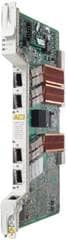
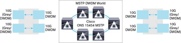
The 4-port 10 Gigabit Small Form-Factor Pluggable (XFP)-based 10 Gigabit Ethernet transponder card for the Cisco® ONS 15454 Multiservice Transport Platform (MSTP) simplifies the integration and transport of OTU2, 10 Gigabit Ethernet (10GE), 10 Gigabit Fibre Channel (10G FC), and OC-192/STM-64 interfaces and services into enterprises or metropolitan-area (metro) and regional service provider networks (Figure 1).
Background
Metro transport networks must support numerous service demands, from low-rate DS-1/T1, DS-3/E3, 10/100BASE-T, and OC-3/STM-1 to higher-rate OC-12/STM-4, Gigabit Ethernet, OC-48/STM-16, OC-192/STM-64, 10 Gigabit Ethernet, 10 Gigabit Fibre Channel, and OC-768/STM-256 services. The flexibility to support multiple rates brings huge savings in terms of operating and management costs.
Product Overview
The OTU2 XPonder consists of a 4-port XFP-based 10-Gigabit transponder that supports multiple bit-rate signals over a 100-GHz-spaced, ITU-compliant wavelength:
● OC-192/STM-64 (9.95328 Gbps)
● 10GE WAN PHY (9.95328 Gbps)
● 10GE LAN PHY (10.3125 Gbps)
● 10G FC (10.518 Gbps)
● OTU-2
◦ Standard G.709 (10.70923 Gbps)
◦ G.709 overclocked to transport 10GE as defined by ITU-T G; Sup43 Clause 7.1 (11.0957 Gbps)
◦ G.709 overclocked to transport 10GE as defined by ITU-T G; Sup43 Clause 7.2 (11.0491 Gbps)
◦ G.709 proprietary overclocking mode to transport 10G FC (11.3168 Gbps)
The OTU2 XPonder card is a plug-in module to the Cisco ONS 15454 MSTP, enabling a cost-effective architecture for delivering high-rate 10-Gbps services. The OTU2 XPonder card architecture contains a single client interface that is mapped to a single line interface, without accessing the Cisco ONS 15454 shelf cross-connect fabric (Figure 2).
You can independently configure each of the four interfaces to support the Optical Transport Network (OTN) wrapper. Combining the XFP and OTN configuration enables multiple configurations. For example, two gray XFPs with no OTN on 2-port and 2-DWDM XFPs with OTN wrapper enabled allow this card to act as two 10G transponders in a single board. Using amplification and dispersion compensation, the OTU2 XPonder card is capable of a 1000-km reach. When operated within the outlined specifications, each card will transport the 10-Gbps signal with a maximum bite error rate (BER) of 10E-15.
The OTU2 XPonder cards are deployable in the 12 multiservice interface card slots of the Cisco ONS 15454 platform, in systems with or without cross-connect cards. The only required common card is the appropriate timing, communications, and control card (TCC2P). It is therefore possible to have twenty-four 10G transponders on a single Cisco ONS 15454 MSTP shelf.
Operating Modes
You can configure boards to operate in the following modes:
● Two 10G transponders
● Two 10G regenerators, Forward Error Correction/Enhanced Forward Error Correction (FEC/E-FEC) equipping the four ports with DWDM XFP
● One 10G regenerator, E-FEC/E-FEC equipping two ports with DWDM XFP
● Fiber-switched protected 10G transponder
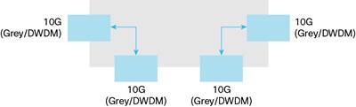
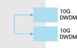
In the operating mode shown in Figure 3, the Cisco ONS 15454 OTU2 XPonder card behaves like two 10G multirate transponders. Port 1 behaves as a client connected with port 3, which behaves as a trunk. The same applies to port 2 as a client and port 4 as a trunk. In this configuration, G.709 on the client port is disabled.
Proper pluggables are inserted in the ports according to traffic requirements.
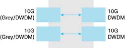
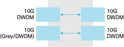
In the operating mode shown in Figure 4, the Cisco ONS 15454 OTU2 XPonder card behaves like two 3R regenerators. Port 1 behaves as a trunk connected with port 3, which behaves as a trunk. The same is true for ports 2 and 4. In this configuration you can enable G.709 on all the ports. Please note that the FEC coding algorithm is asymmetric because ports 1 and 2 support standard FEC (GFEC ITU-T G.975) whereas ports 3 and 4 support E-FEC (ITU-T G.975.1).
Proper pluggables are inserted in the ports according to traffic requirements.
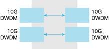
In the operating mode shown in Figure 5, the Cisco ONS 15454 OTU2 XPonder card behaves like a single 3R regenerator. Only ports 3 and 4 are enabled as trunks, whereas ports 1 and 2 are deactivated.
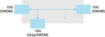
In the operating mode shown in Figure 6, the Cisco ONS 15454 OTU2 XPonder card behaves like an MR 10G transponder and an MR 3 regenerator with FEC on one port and EFEC on the other port.
In the operating mode shown in Figure 7, the Cisco ONS 15454 OTU2 XPonder card provides a DWDM trunk protection for a single client input.
Proper pluggables are inserted in the ports according to traffic requirements.
Pluggable Interfaces
The OTU2 XPonder card is a plug-in module to the Cisco ONS 15454 MSTP, enabling a cost-effective architecture for delivering high-rate 10-Gbps services. The OTU2 XPonder card architecture contains a single client interface that is mapped to a single line interface, without accessing the Cisco ONS 15454 shelf cross-connect fabric. The interfaces are based on XFP Multi Source Agreement (MSA). Various types can be used depending on reach and application:
● ONS-XC-10G-S1= (P/N 10-2012-02)
◦ 10G-1200-SM-LL-L, 10GE BASE-LR, 10GE BASE-LW, OC-192 SR1, STM-64 I-64.1, and OTU-2 at 10.7G
● ONS-XC-10G-S1= (P/N 10-2012-03)
◦ 10G-1200-SM-LL-L, 10GE BASE-LR, 10GE BASE-WR, OC-192 SR1, STM-64 I.64, OTU-2 at 10.7G, 11.05G, and 11.09G
● ONS-XC-10G-I1= (P/N 10-2193-02)
◦ 10GE BASE-ER, 10GE BASE-EW, OC-192 IR2, and STM-64 S-64.2
● ONS-XC-10G-L2= (P/N 10-2194-02)
◦ 10GE BASE-ZR, OC-192 LR2, and G959.1 P1L1-2D2
● ONS-XC-10G-SR-MM= (P/N 10-2420-01)
◦ 1200-MX-SN-I, 10GE BASE-SR, OTU-2 at 10.7G, 11.05G, and 11.09
● ONS-XC-10G-xx.x (xx.x from 30.3 to 61.4 - P/N version 01)
◦ DWDM for 10GE LAN PHY; WAN PHY; STM-64; OC-192; 10G FC; and OTU2 at 10.7G, 11.05G, and 11.09G
● ONS-XC-10G-xx.x (xx.x from 30.3 to 61.4 - P/N version 02)
◦ DWDM for 10GE LAN PHY; WAN PHY; STM-64; OC192, 10G FC; and OTU2 at 10.7G, 11.05G, 11.09G, and 11.3G
● ONS-XC-10G-EPxx.x (xx.x from 30.3 to 61.4 - P/N version 01)
◦ DWDM for 10GE LAN PHY; WAN PHY; STM-64; OC192; 10G FC; and OTU2 at 10.7G, 11.05G, 11.09G, and 11.3G
● ONS-XC-10G-C (P/N 10-2480-01)
◦ DWDM for 10GE LAN PHY; WAN PHY; STM-64; OC192; 10G FC; and OTU2 at 10.7G, 11.05G, 11.09G, and 11.3G
Enhanced FEC Capability
An important feature of the OTU2 XPonder card is the ability to configure the FEC mode. Ports 1 and 2 have two modes of operation, NO FEC and FEC, whereas ports 3 and 4 can also be configured in E-FEC mode.
You can configure error-coding performance:
● NO FEC: No Forward Error Correction
● FEC: Standard G.975 Reed-Salomon algorithm
● E-FEC: Standard G.975.1 two orthogonally concatenated block (BCH) super FEC codes; this FEC scheme contains three parameterizations of the same scheme of two BCH codes, with the constructed code decoded iteratively to achieve the expected performance
Protocol Transparency
The OTU2 XPonder card provides transparent wavelength services on the Cisco ONS 15454 platform.
For SONET- or SDH-based client payloads, when provisioned in transparent operating mode, the card passes all of the SONET/SDH overhead bytes transparently. The card monitors important SONET/SDH overhead bytes, such as B1 (section BIP-8) and J0 (section trace), to allow fault isolation and performance-monitoring capabilities. Termination of the line data communications channel (LDCC) is user-provisionable to enable the platform processor to route the DCC information for intracarrier networking or to allow the DCC information to be transported untouched through the general communications channel (GCC) of the digital wrapper for intercarrier networking.
For 10 Gigabit Ethernet and OC-192/STM-64 payloads, digital-wrapper technology (G.709) is used to add a management wrapper to the service, allowing the OTU2 XPonder card to transparently forward the payload while enabling performance metrics to be derived to help ensure circuit service quality.
For OTU2 clients, the XPonder card can transparently transport OPUk and ODUk terminating OTUk as a fully standard G.709 regenerator.
LAN-to-WAN Conversion
The OTU2 XPonder card in the Cisco ONS 15454 MSTP Release 9.1 and later can convert incoming 10GE LAN PHY signals into 10GE WAN PHY signals at the far-end egress port.
The 10GE LAN PHY-to-WAN PHY conversion is implemented according to the standard defined in IEEE 802.3: WIS (WAN interface sublayer). The 10GE LAN PHY interfaces have an effective line rate of 10.3125 Gbps (10 Gbps of data traffic encoded in a 64B/66B protocol). The 10GE WAN PHY interfaces conform to the SONET/SDH standards to achieve 9.95328 Gbps and allow service providers to use their existing SONET/SDH Layer 1 infrastructure.
WAN PHY is used to transport 10 Gigabit Ethernet across SDH/SONET or WDM systems without having to directly map the Ethernet frames into SDH/SONET first. The WAN PHY variants correspond at the physical layer to 10GBASE-SR, 10GBASE-LR, 10GBASE-ER, and 10GBASE-ZR, respectively, and hence use the same types of fiber and support the same distances.
Proactive FRR Regeneration implementation
Fast Reroute (FRR) is a Layer 3 protection mechanism that allows for switching of the data path without relying on Layer 1 concerns. The switch in most of the cases happens with little or no loss of data and is guaranteed to happen within 50 milliseconds. The switch would indirectly be triggered by the events that would bring the interface down, resulting in almost certain data loss during the time when defects are detected until a FRR switch is completed.
With IP over DWDM (IPoDWDM), the FEC circuitry resides on a router line card. Therefore, the router has visibility into the BER statistics before the FEC mechanism corrects these errors, allowing the router to realize that the working path is degrading beyond a reasonable point (which is defined by a user-settable threshold). At this point, the router can start its protection logic and establish a protection path while traffic continues to flow on the degrading working path. Depending on the failure mode, the router may have tens or even hundreds of milliseconds to move away from the working path before the FEC mechanism fails.
The FEC mechanism detects failures before they actually happen and also corrects errors introduced during transmission or due to a degrading signal. It was proposed that the DWDM PLIMS trigger an FRR switch based on the number of FEC corrected bits. The number of FEC corrected bits would provide a good indication that the line is about to have a failure. FEC-based FRR therefore allows for triggering the switch before that failure happens with little or no loss of data. In fact, the FEC function is able to correct a high BIR (up to 10E-3) providing an error-free signal to the line card connected to the PLIM. Triggering the FRR with a lower BER will cause a FRR before any packet is lost.
The prevailing video encoding is based on MPEG-2 and MPEG-4 standards, which use differential coding of the frame with reference to a full frame that is sent only relatively infrequently. When this frame (called the I-frame) is lost, a large number of users may experience a visible outage on their screens, lasting for up to several seconds. High-resolution encoding schemes, such as MPEG-4, are actually more susceptible to longer outages because I‑frames are less common in the data stream. For this reason we argue that it is important to strive to minimize the packet loss even below the SONET/SDH benchmark, ideally aiming for zero packet loss.
Starting with Release 9.2, OTU2XP cards support Proactive Protection Regeneration, which notifies the routers of the incoming FEC errors. This feature involves modifying the G709 protection bytes in ODverHead FRR Regen is supported on ports of OTU2XP only when the card is in the “Standard Regen” and “Enhanced FEC” card modes for 10GE payloads.
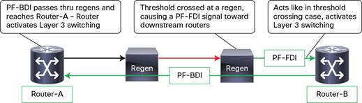
● When a span between two Routers an OTU2 XP is used as OTU2 Regen is degrading, the downstream router will not be aware of it. (Therefore, the router will not switch to an alternate path.)
● The OTU2-XP will signal to the downstream router about the degradation. This signal is PF-FDI (using the APS/PCC bytes of the G.709 ODU OH).
● The router integrates pre-FEC error backward defect indicator (PF-FDI) for three frames and then acts as if it has detected the BER threshold crossing.
● Router B activates its Layer 3 switching.
● Router B raises a PF-BDI flag to ask router A to switch. This PF-BDI will propagate through the OTU2-XP.
● When router A gets this PF-BDI message, router A also activates its Layer 3 switching.
OTU2-XP allows you to extend FRR when OTU2 regeneration is required between the routers, sending PF-FDI when it sees a degrading link.
Flow-Through Timing
The OTU2 XPonder card allows the timing to “flow through” from client to line optical interfaces. Receive timing from one interface (client or line) is used to time the other transmitter interface (line or client). This flow-through timing enables the transported signal to remain independent from the node timing. It is also possible to extract the clock from any of the available ports and pass it to the TCC, but the card does not use the clock coming from the TCC.
Flexible Protection Mechanisms
The Cisco ONS 15454 OTU2 XPonder card provides flexible protection capabilities for both client and DWDM line interfaces, supporting numerous network configurations to uphold the various service-level agreements (SLAs) required by the customer application.
● Unprotected client and line: This configuration has no client terminal interface, transponder card, or DWDM line protection. The client signal is transported over a single unprotected transponder card. This configuration is suitable for transporting client payloads over a DWDM network that is being protected by a Layer 2 or Layer 3 protocol.
● Y-cable client interface: This configuration provides transponder equipment protection without client terminal equipment interface protection. A single client interface is split into two transponder cards using a Y-protection device.
● Fiber-switched protection: This configuration provides redundant DWDM trunk interface protection for a single unprotected client interface.
Management
The Cisco ONS 15454 provides comprehensive management capabilities to support operations, administration, maintenance, and provisioning (OAM&P) capabilities through the integrated Cisco Transport Controller Craft Interface with support from the Cisco Transport Manager Element Management System (EMS). The Cisco ONS 15454 OTU2 XPonder card incorporates provisionable digital-wrapper (G.709) functions, providing per-wavelength performance-management capabilities, especially for services being transported transparently across the network. Without the digital-wrapper functions, a carrier transporting a service transparently would be unable to identify network impairments that may degrade the transported signal and exceed SLA requirements.
The GCC of the digital wrapper allows a separate communications channel on a per-wavelength basis. This GCC allows the Cisco ONS 15454 MSTP to extend its advanced network autodiscovery capabilities to DWDM-based services. The integrated Cisco ONS 15454 MSTP Transport Controller Craft Manager and the Cisco Transport Manager EMS give you OAM&P access for the system.
Performance Monitoring
The performance-monitoring capabilities of the Cisco ONS 15454 OTU2 XPonder card provide support for both transparent and nontransparent signal transport. Calculation and accumulation of the performance-monitoring data is in 15-minute and 24-hour intervals.
For SONET/SDH signals, standard performance-monitoring and threshold-crossing conditions and alarms are supported per Telcordia GR-474, GR-2918, ITU G.783, and ETS 300 417-1 standards.
Table 1. SONET/SDH Performance Monitoring
| SONET Performance Monitoring |
Section |
Line (Near End) |
Line (Far End) |
| Number of coding violations (CV) |
CV-S |
CV-L |
CV-L |
| Number of errored seconds (ES) |
ES-S |
ES-L |
ES-L |
| Number of severely errored seconds (SES) |
SES-S |
SES-L |
SES-L |
| Number of severely errored frame seconds (SEFS) |
SEFS-S |
- |
- |
| Number of unavailable seconds (UAS) |
- |
UAS-L |
UAS-L |
| Number of failure counts (AIS/RFI detected) (FC) |
- |
FC-L |
FC-L |
| SDH Performance Monitoring |
Regenerator Section |
Multiplex Section |
Multiplex Section |
| Number of errored seconds (ES) |
RS-ES |
MS-ES |
MS-ES |
| Error seconds ratio (ESR) |
RS-ESR |
MS-ESR |
MS-ESR |
| Number of severely errored seconds (SES) |
RS-SES |
MS-SES |
MS-SES |
| Severely errored seconds ratio (SESR) |
RS-SESR |
MS-SESR |
MS-SESR |
| Number of background block errors (BBE) |
RS-BBE |
MS-BBE |
MS-BBE |
| Background block errors ratio (BBER) |
RS-BBER |
MS-BBER |
MS-BBER |
| Number of unavailable seconds (UAS) |
RS-UAS |
MS-UAS |
MS-UAS |
| Number of errored blocks (EB) |
RS-EB |
MS-EB |
MS-EB |
For 10 Gigabit Ethernet signals, standard performance parameters for transmit and receive signals are based on Remote Monitoring (RMON) Ethernet compliant with RFCs 1573, 1757, 2233, 2358, 3273, and 3635.
For 10G Fibre Channel the following parameters are available:
● txTotalPkts, rxTotalPkts, mediaIndStatsTxFramesBadCRC,
● mediaIndStatsRxFramesTruncated, ifOutOversizePkts, mediaIndStatsRxFramesTooLong,
● mediaIndStatsRxFrameBadCRC, ifOutOctects, ifInOctects, ifInErros
Each digital-wrapper channel is monitored per ITU-T digital-wrapper requirements (G.709).
Table 2. OTN Performance Monitoring
| OTUk SM Counters |
ODUk PM Counters |
Description |
| BBE-SM |
BBE-PM |
Number of background block errors |
| BBER-SM |
BBER-PM |
Background block errors ratio |
| ES-SM |
ES-PM |
Number of errored seconds |
| ESR-SM |
ESR-PM |
Errored seconds ratio |
| SES-SM |
SES-PM |
Number of errored seconds ratio |
| SESR-SM |
SESR-PM |
Severely errored seconds ratio |
| UAS-SM |
EAS-PM |
Number of unavailable seconds |
| FC-SM |
FC-PM |
Number of failure counts |
FEC/EFEC performance monitoring parameters are also available; they are listed in Table 3.
Table 3. FEC Performance Monitoring
| Counters |
Description |
| Bit errors |
Number of corrected bit errors |
| Uncorrectable words |
Number of uncorrectable words |
Optical parameters on the DWDM line interface are supported, including laser bias, transmit optical power, and receiver optical power.
The OTU2 XPonder card incorporates faceplate-mounted LEDs to provide a quick visual check of the operational status of the card. An orange circle is printed on the faceplate, indicating the shelf slots where the card can be installed.
Application Description
The Cisco ONS 15454 OTU2 XPonder card provides the capability to support two 10G transponders on a single-slot card, doubling the 10G wavelength density over the Cisco ONS 15454 shelf (Figure 9). Using DWDM XFP capability delays the cost for additional wavelength.
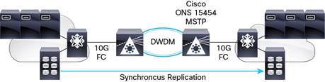
The OTU2 XPonder card provides a full set of 10G Fibre Channel performance-monitoring parameters (Figure 10). Even if it is not equipped with the distance-extension mechanism, the XPonder easily supports 10G Fibre Channel generated by Cisco MDS 9000 Series interfaces.
In a single shelf up to an eighteen 10G Fibre Channel signals terminal system can be accommodated.
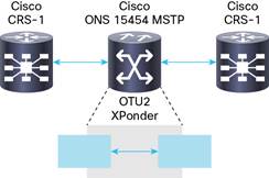
The OTU2 XPonder card provides the capability to support the 3R function in a single card. Because two ports can support E-FEC and two ports can support GFEC only, two possible configurations are allowed, depending on network topology: single regeneration E-FEC/E-FEC or double regeneration FEC/E-FEC. Regeneration is fully compliant with the G.709 standard, allowing you to transparently transport the ODU2 frame and terminate the OTU frame. It also can be used as a double regeneration for DWDM XENPAK/X2/XFP optical pluggable interfaces placed on other Cisco routers or switches in IPoWDM scenarios.
The Cisco Advantage
The Cisco ONS 15454 optical transport solution offers significant advantages over traditional network elements offering 10-Gbps interfaces, including the following:
● Outstanding service densities: The Cisco ONS 15454 platform supports up to 240 Gigabit Ethernet interfaces per shelf. When this platform is installed in a typical central-office bay frame, a bay can support up to 960 Gigabit Ethernet interfaces.
● Common line cards and chassis: Optical line cards are not restoration-type-dependent, reducing sparing costs and technician confusion. Additionally, as networks and customer interface demands evolve, you can easily redeploy optical circuit packs as necessary.
● Single software load: One software load supports all restoration types, eliminating unnecessary guesswork when ordering. All protection configurations are covered by a single right-to-use software license. After you purchase the software, all features and functions are available to you.
● Common chassis: A common chassis supporting all optical interface speeds allows the technician to spend time deploying bandwidth and services instead of learning about multiple equipment platforms. Many equipment vendors offer optical-line-speed-specific platforms (for example, OC-3/STM-1 or OC-12/STM-4) and categorize platforms by restoration mechanisms (for example, UPSR/SNCP, 2F-BLSR/MS-SPR, and 4F-BLSR/MS-SPR). This approach both causes ordering confusion and brings into question whether the inventoried equipment will accommodate the functions required to support the desired application. The line-rate and restoration flexibility of the Cisco ONS 15454 platform makes ordering and deployment quick and easy.
● Multiservice interface selection: DS-1/E1 through OC-192/STM-64, Ethernet, Fast Ethernet, Gigabit Ethernet, and 10 Gigabit Ethernet interfaces are all supported, thus eliminating the “missing-interface” problem that occurs with many vendors’ bit-rate-specific product offerings.
The Cisco ONS 15454 MSTP, the industry’s leading metro optical transport platform, delivers supercharged SONET/SDH transport, integrated optical networking, superior multiservice interfaces, and competitive economic benefits.
Cisco ONS 15454 OTU2 XPonder Card Features and Specifications
Compact Design
● Single-width card slot design for high-density, 10 Gigabit multirate solutions
● Up to 12 Cisco ONS 15454 OTU2 XPonder cards per shelf assembly (240 Gbps), and up to 36 cards per bay (720 Gbps)
Flexible Restoration Options
● Fiber switched
● Client Y-protection
● Unprotected (0 + 1)
Regulatory Compliance
Table 4 lists regulatory compliance information, Table 5 gives system requirements, Table 6 gives card specifications, and Table 7 gives ordering information.
Table 4. Regulatory Compliance Information
|
● Mexico
|
|
|
● EN or IEC 60825-1 Consol. Ed. 1.2 - incl. am1+am2 (2001-08)
|
|
Table 5. System Requirements
| Component |
Cisco ONS 15454 ANSI |
Cisco ONS 15454 ETSI |
| Processor |
TCC2P and TCC2 |
TCC2P and TCC2 |
| Cross-connect |
All (not required) |
All (not required) |
| Shelf assembly |
15454-SA-HD or 15454-SA-HD-DDR shelf assembly with CC-FTA version fan-tray assembly |
15454-SA-ETSI shelf assembly with SDH CC-FTA version fan-tray assembly |
| System software |
Release 9.0 or later |
Release 9.0 or later |
| Slot compatibility |
1 to 6 and 12 to 17 |
1 to 6 and 12 to 17 |
Table 6. Card Specifications
| Specification |
|
| Management |
|
| Card LEDs
● Failure (FAIL)
● Active/standby (ACT/STBY)
● Signal fail (SF)
Client port LEDS
● Active input signal
DWDM port LEDs
● Active input signal
● Output wavelength
|
Red Green/yellow Yellow
Green
Green Green |
| Power |
|
| Card power draw
● Typical
● Maximum
|
51W (with no pluggables) 70W (fully loaded) |
| Physical |
|
| Occupies one slot |
|
| 2.43 lb (1.1 kg) |
|
| Reliability and Availability |
|
| MTBF |
348,046 hours |
| Latency TXP Mode (End to End) |
|
| 10.4 microsecond |
|
| Latency Regenerator Mode (Unit Level) |
|
| G.709 On - Standard FEC G.709 On - Enhanced FEC |
14.2 microseconds 147.6 microseconds |
| Operating Environment |
|
| Temperature |
23 to 131°F (-5 to 55°C) |
| Humidity |
5 to 95% noncondensing |
| Storage Environment |
|
| Temperature |
23 to 131°F (-5 to 55°C) |
| Humidity |
5 to 95% noncondensing |
Table 7. Ordering Information
| Part Number |
Description |
| 15454-OTU2-XP= |
Ethernet 4-10 Gigabit Ethernet Xponder |
| ONS-XC-10G-xx.x= |
OC-192/STM64/10 Gigabit Ethernet, XFP, 15xx.xx, 100 GHz, LC |
| ONS-XC-10G-S1= |
10 Gigabit SFP OC-192/STM-64/10 GE/10-Gbps Fibre Channel, 1310 SR-SM LC connectors |
| ONS-XC-10G-I2= |
XFP - OC192/STM64/10GE - 1550 IR/SH2 - SM LC |
| ONS-XC-10G-L2= |
XFP - OC192/STM64 - 1550 LR2 - SM LC |
| ONS-XC-10G-SR-MM= |
XFP - 10GE/10G FC - 850 SR - MM LC |
| ONS-XC-10G-C= |
10G Multirate Full C Band Tunable DWDM XFP, 50 GHz, LC |
| ONS-XC-10G-EPxx.x= |
10G MR, XFP, Edge Performance 15xx.xx, 100 GHz, LC |
For pluggable support and software release dependency, please refer to the Pluggables Configuration Guide at: http://www.cisco.com/en/US/prod/collateral/optical/ps5724/ps2006/brochure_c02-452560.html.
 Feedback