- Node Reference
- Turning Up a Node
- Performing Node Acceptance Tests
- Network Reference
- Turning Up a Network
- Creating Optical Channel Circuits and Provisionable Patchcords
- Monitoring Performance
- Managing the Node
- Changing DWDM Card Settings
- Alarm and TCA Monitoring and Management
- Managing Network Connectivity
- Upgrade, Add, and Remove Cards and Nodes
- Maintaining the Node
- Administrative and Service States
- SNMP
- CTC Enhancements, Operations, and Shortcuts
- Network Element Defaults
- Index
- NTP-G341 Setting Up Secure Access to TL1
- OpenSSH Version
- NTP-G29 Setting Up SNMP
- NTP-G328 Adding, Modifying, or Deleting ANS Parameters
- NTP-G30 Installing the DWDM Cards
- NTP-G179 Installing the Transponder and Muxponder Cards
- NTP-G123 Installing the Filler Cards
- NTP-G34 Installing Fiber-Optic Cables on DWDM Cards and DCUs
- NTP-G140 Installing Fiber-Optic Cables Between Terminal, Hub, or ROADM Nodes
- DLP-G315 Installing Fiber-Optic Cables From the 32WSS/32DMX Cards to the Standard Patch Panel Tray
- DLP-G316 Installing Fiber-Optic Cables from TXP, MXP Cards to the Standard Patch Panel Tray
- DLP-G356 Installing Fiber-Optic Cables from the 32WSS/32DMX Cards to the Deep Patch Panel Tray
- DLP-G427 Rerouting Fiber-Optic Cables in the 40-Channel Patch Panel Tray
- DLP-G428 Installing Fiber-Optic Cables from the 40-WSS-C/40-WSS-CE and 40-DMX-C/40-DMX-CE Cards to the 40-Channel Patch Panel Tray
- DLP-G357 Installing Fiber-Optic Cables from the TXP, MXP Cards to the Deep Patch Panel Tray or 40-Channel Patch Panel Tray
- DLP-G496 Creating an SNMPv3 User
- DLP-G497 Create MIB Views
- DLP-G498 Create Group Access
- DLP-G499 Configure SNMPv3 Trap Destination
- DLP-G500 Deleting SNMPv3 Trap Destination
- DLP-G501 Creating Notification Filters
- DLP-G502 Manually Configuring the SNMPv3 Proxy Forwarder Table
- DLP-G503 Automatically Configuring the SNMPv3 Proxy Forwarder Table
- DLP-G504 Manually Configuring the SNMPv3 Proxy Trap Forwarder Table
- DLP-G505 Automatically Configuring the SNMPv3 Proxy Trap Forwarder Table
- DLP-G789 Enable RSVP on an Interface
- DLP-G790 Create a Static LMP Connection
Turning Up a Node
This chapter explains how to provision a single Cisco NCS node and turn it up for service, including assigning the node name, date, and time; provisioning timing references; provisioning network attributes such as IP address and default router; setting up users and user security; installing cards; and creating DWDM connections.
 Note | The procedures and tasks described in this chapter for the Cisco NCS platform is applicable to the Cisco NCS 2002 and Cisco NCS 2006 platforms, unless noted otherwise. |
Note | Cisco Transport Controller (CTC) views referenced in these procedures depend on the mode. In single-shelf mode, the views are network, node, and card. In multishelf mode, the views are network, multishelf, shelf, and card. For more information about CTC views, refer to CTC Enhancements, Operations, and Shortcuts. |
Note | In this chapter, “100G-LC-C card” refers to the 15454-M-100G-LC-C card. “10x10G-LC” refers to the 15454-M-10x10G-LC card. “CFP-LC” refers to the 15454-M-CFP-LC card. |
- NTP-G341 Setting Up Secure Access to TL1
- OpenSSH Version
- NTP-G29 Setting Up SNMP
- NTP-G328 Adding, Modifying, or Deleting ANS Parameters
- NTP-G30 Installing the DWDM Cards
- NTP-G179 Installing the Transponder and Muxponder Cards
- NTP-G123 Installing the Filler Cards
- NTP-G34 Installing Fiber-Optic Cables on DWDM Cards and DCUs
- NTP-G140 Installing Fiber-Optic Cables Between Terminal, Hub, or ROADM Nodes
- NTP-G185 Installing Fiber-Optic Cables between Mesh Nodes
- NTP-G191 Installing Fiber-Optic Cables on Passthrough ROADM Nodes
- NTP-G141 Installing Fiber-Optic Cables for Y-Cable Protection Modules
- NTP-G39 Verifying OSCM Transmit Power
- NTP-G210 Provisioning Node for SNMPv3
- NTP-G211 Provisioning Node to Send SNMPv3 Traps
- NTP-G212 Manually Provisioning a GNE/ENE to Manage an ENE using SNMPv3
- NTP-G213 Automatically Provisioning a GNE to Manage an ENE using SNMPv3
- NTP-G214 Manually Provisioning a GNE/ENE to Send SNMPv3 Traps using SNMPv3
- NTP-G215 Automatically Provisioning a GNE/ENE to Send SNMPv3 Traps Using SNMPv3
- NTP-G355 Provisioning OTDR for TNCS-O Cards
NTP-G341 Setting Up Secure Access to TL1
|
This procedure provisions the nodes for secure access to TL1. |
|
| NTP-G26 Set Up CTC Network Access | |
OpenSSH Version
The OpenSSH version that is currently supported is 3.5.9.1 and will be upgraded in a future release.
Note | The OpenSSH has been upgraded to Cisco SSH Release 1.4. |
NTP-G29 Setting Up SNMP
|
This procedure provisions the SNMP parameters so that you can use SNMP management software with the Cisco NCS. |
|
| Step 1 | In node view (single-shelf mode) or multishelf view (multishelf mode), click the tabs. | ||||
| Step 2 | In the Trap Destinations area, click Create. | ||||
| Step 3 | Complete the following in the
Create SNMP Trap Destination dialog box.
| ||||
| Step 4 | Click the node IP address in the Trap Destinations area. Verify the SNMP information that appears in the Selected Destination list. | ||||
| Step 5 | If you want the SNMP agent to accept SNMP SET requests on certain MIBs, click the Allow SNMP Sets check box. If this box is not checked, SET requests are rejected. | ||||
| Step 6 | If you want to set up the
SNMP proxy feature to allow network management, message reporting, and
performance statistic retrieval across firewalls, click the Allow SNMP Proxy
check box located on the SNMP tab.
| ||||
| Step 7 | Click Apply. | ||||
| Step 8 | If you are setting up SNMP
proxies, you can set up to three relays that send SNMP trap error counts back
to the NE for each trap destination address:
| ||||
| Step 9 | Click Apply.
Stop. You have completed this procedure. |
DLP-G351 Deleting a Card in CTC
|
This task deletes a card from an NCS slot that is provisioned in CTC. |
|
Note | It is recommended that the card be physically removed from its slot after deleting it from CTC. |
| Step 1 | Verify that the following
conditions are not present. (During node turn-up, these conditions are normally
not present):
If any of these conditions exist, do not continue. You will not be able to delete the card until the card is removed from protection groups; circuits, DCC, and GCCs are deleted; a different timing source is provisioned, and the LMP link or channel is deleted.
|
| Step 2 | On the shelf graphic in CTC, right-click the card that you want to remove and choose Delete Card. |
| Step 3 | Return to your originating procedure (NTP). |
DLP-G353 Pre-provisioning a Slot
|
This task pre-provisions a NCS slot in CTC. Pre-provisioning of all the slots in the shelf is normally performed when you complete the NTP-G143 Importing the Cisco Transport Planner NE Update Configuration File procedure. Use this task if you need to manually pre-provision a slot. All slot pre-provisioning must be based on the Cisco Transport Planner shelf layout prepared for your site. |
|
| Step 1 | In node view (single-shelf mode) or multishelf view (multishelf mode), right-click an empty slot where you want to install a card. | |||||||||||||||||||||||||||||||||||||||||||||||||||||||||||||||||||||||||||||||||||||||||||||||||||||||||||||||||||||||||||||||||||||||||||||||||||||||||||||||||||||||||||||||||||||||
| Step 2 | From the Add Card shortcut
menu, choose the card type that will be installed based on the
Cisco Transport Planner shelf layout. Only cards that can be installed in the
slot appear in the Add Card shortcut menu. The following table shows the Add
Card shortcut menu, submenu, card groups, and menu options or cards that they
reference.
| |||||||||||||||||||||||||||||||||||||||||||||||||||||||||||||||||||||||||||||||||||||||||||||||||||||||||||||||||||||||||||||||||||||||||||||||||||||||||||||||||||||||||||||||||||||||
| Step 3 | Repeat
Step 2 until all the
cards shown in the Cisco Transport Planner shelf layout are provisioned in CTC.
Stop. You have completed this procedure. | |||||||||||||||||||||||||||||||||||||||||||||||||||||||||||||||||||||||||||||||||||||||||||||||||||||||||||||||||||||||||||||||||||||||||||||||||||||||||||||||||||||||||||||||||||||||
DLP-G693 Configuring the Amplifier Card
|
This task configures the optical parameters and threshold values of the amplifier card. |
|
| Step 1 | Display the amplifier card in card view. | |||||||||||||||
| Step 2 | Click the tabs. | |||||||||||||||
| Step 3 | Select the working mode from the Card Working Mode drop-down list. | |||||||||||||||
| Step 4 | Change to node view (single-shelf mode) or multishelf view (multishelf mode), then click the tabs. | |||||||||||||||
| Step 5 | From the Selector area, select the amplifier slot. If the default parameters are present, continue with Step 6. If not, click Add to add the Channel LOS Threshold, Amplifier Tilt, Power, and Amplifier Working Mode parameters. To add the ANS parameters, see the DLP-G541 Adding an ANS Parameter task for instructions. | |||||||||||||||
| Step 6 | Click the value of the ANS
parameter that you want to modify and enter the new value specified in the
following table. To modify the ANS parameters, see the
DLP-G681 Modifying an ANS Parameter
task for instructions.
| |||||||||||||||
| Step 7 | Click Apply. | |||||||||||||||
| Step 8 | Click the tabs. | |||||||||||||||
| Step 9 | Click Launch ANS. | |||||||||||||||
| Step 10 | In the Apply Launch ANS dialog box, click Yes. | |||||||||||||||
| Step 11 | In the Launch ANS confirmation dialog box, click OK. | |||||||||||||||
| Step 12 | In node view (single-shelf mode) or multishelf view (multishelf mode), click the tabs. | |||||||||||||||
| Step 13 | Verify the following in the Results column: | |||||||||||||||
| Step 14 | Verify that the Set By column displays t he value “ANS” or “APC” as the application that sets the ANS parameter. | |||||||||||||||
| Step 15 | Return to your originating procedure (NTP). |
DLP-G694 Configuring the PSM Card
| Step 1 | In node view (single-shelf mode) or multishelf view (multishelf mode), click the tabs. | |||||||||||||||
| Step 2 | From the Selector area, select the PSM slot. If the default parameters are present, continue with Step 3. If not, click Add to add the Channel LOS Threshold and VOA Attenuation parameters. To add the ANS parameters, see the DLP-G541 Adding an ANS Parameter for instructions. | |||||||||||||||
| Step 3 | Click the value of the ANS
parameter that you want to modify and enter the new value specified in the
following table. To modify the ANS parameters, see the
DLP-G681 Modifying an ANS Parameter
for instructions.
| |||||||||||||||
| Step 4 | Click Apply. | |||||||||||||||
| Step 5 | Click the tabs. | |||||||||||||||
| Step 6 | Click Launch ANS. | |||||||||||||||
| Step 7 | In the Apply Launch ANS dialog box, click Yes. | |||||||||||||||
| Step 8 | In the Launch ANS confirmation dialog box, click OK. | |||||||||||||||
| Step 9 | In node view (single-shelf mode) or multishelf view (multishelf mode), click the tabs. | |||||||||||||||
| Step 10 | Verify the following in the Results column: | |||||||||||||||
| Step 11 | Verify that the Set By column displays t he value “ANS” or “APC” as the application that sets the ANS parameter. | |||||||||||||||
| Step 12 | Return to your originating procedure (NTP). |
NTP-G328 Adding, Modifying, or Deleting ANS Parameters
|
This procedure allows you to add, modify, or delete ANS parameters for a DWDM node. |
|
Note | It is recommended that you use the Cisco Transport Planner XML configuration file to provision the ANS parameters instead of manually adding all the parameters in CTC. ANS provisioning parameters must be manually changed only by Cisco qualified personnel. Provisioning the ANS parameters incorrectly (either as preamplifier or booster input power thresholds) may impact traffic. |
|
DLP-G541 Adding an ANS Parameter
| Step 1 | In node view (single-shelf mode) or multishelf view (multishelf mode), click the tabs. | ||
| Step 2 | Click Add. The Add ANS Parameter dialog box appears. | ||
| Step 3 | Select the ANS parameter from the Parameter drop-down list. | ||
| Step 4 | In the Port Selection area, complete the following fields:
| ||
| Step 5 | Choose the granularity as OTS or OCH from the Granularity drop-down list.
| ||
| Step 6 | Type or choose the value for the ANS parameter in the Value field. | ||
| Step 7 | Click OK. | ||
| Step 8 | Return to your originating procedure (NTP). |
DLP-G681 Modifying an ANS Parameter
Note | Do not begin this procedure until the Cisco Transport Planner NE Update file is created for the node. You must import the new NE Update file and run ANS to recalculate the ANS parameters for the node. |
 Caution | Modifying ANS parameters on one node requires ANS upgrades on all the other nodes within the network. Do not begin this procedure until you are prepared to complete the upgrade on all the network nodes. |
Caution | This procedure will affect the service of unprotected circuits that pass through the node. |
| Step 1 | In node view (single-shelf mode) or multishelf view (multishelf mode), click the tabs. | |||||||||||||||||||||||||||||||||||||||||||||||||||
| Step 2 | Click the value of the ANS
parameter that you want to modify and enter the new value.
| |||||||||||||||||||||||||||||||||||||||||||||||||||
| Step 3 | Click Apply. | |||||||||||||||||||||||||||||||||||||||||||||||||||
| Step 4 | Click the tabs. | |||||||||||||||||||||||||||||||||||||||||||||||||||
| Step 5 | Click Launch ANS. | |||||||||||||||||||||||||||||||||||||||||||||||||||
| Step 6 | In the Apply Launch ANS dialog box, click Yes. | |||||||||||||||||||||||||||||||||||||||||||||||||||
| Step 7 | In the Launch ANS confirmation dialog box, click OK. | |||||||||||||||||||||||||||||||||||||||||||||||||||
| Step 8 | In node view (single-shelf mode) or multishelf view (multishelf mode), click the tabs. | |||||||||||||||||||||||||||||||||||||||||||||||||||
| Step 9 | Verify the following in the Results column: | |||||||||||||||||||||||||||||||||||||||||||||||||||
| Step 10 | Verify that the Set By column displays t he value “ANS” or “APC” as the application that sets the ANS parameter. | |||||||||||||||||||||||||||||||||||||||||||||||||||
| Step 11 | Return to your originating procedure (NTP). |
DLP-G542 Deleting an ANS Parameter
| Step 1 | In node view (single-shelf mode) or multishelf view (multishelf mode), click the tabs. | ||
| Step 2 | Click the ANS parameter you want to remove.
| ||
| Step 3 | Click Remove, and then Yes. | ||
| Step 4 | Return to your originating procedure (NTP). |
NTP-G30 Installing the DWDM Cards
|
This procedure describes how to install the DWDM multiplexer, demultiplexer, wavelength selective switch, wavelength cross-connect, OSC, PSM, and optical amplifier cards. |
|
|
|
 Warning | This warning symbol means danger. You are in a situation that could cause bodily injury. Before you work on any equipment, be aware of the hazards involved with electrical circuitry and be familiar with standard practices for preventing accidents. To see translations of the warnings that appear in this publication, refer to the Regulatory Compliance and Safety Information document for the appropriate Cisco chassis. Statement 274 |
Warning | During this procedure, wear grounding wrist straps to avoid ESD damage to the card. Do not directly touch the backplane with your hand or any metal tool, or you could shock yourself. Statement 94 |
Warning | Class I (CDRH) and Class 1M (IEC) laser products. Statement 1055 |
Warning | Invisible laser radiation may be emitted from the end of the unterminated fiber cable or connector. Do not view directly with optical instruments. Viewing the laser output with certain optical instruments (for example, eye loupes, magnifiers, and microscopes) within a distance of 100 mm may pose an eye hazard. Statement 1056 |
Warning |
High-performance devices on this card can get hot during operation. To remove the card, hold it by the faceplate and bottom edge. Allow the card to cool before touching any other part of it or before placing it in an antistatic bag. Statement 201
Warning | The optical Add/Drop cards and ROADM cards need a maximum of 15 minutes to warm up to ambient temperature, after it is inserted into a shelf. The card configurations or settings are unavailable during this period. |
Caution | Always use the supplied electrostatic discharge (ESD) wristband when working with a powered NCS. For detailed instructions on how to wear the ESD wristband, refer to the Electrostatic Discharge and Grounding Guide for Cisco NCS 2000 Series. |
Note | For United States installations, complies with the United States Federal Drug Administration Code of Federal Regulations Title 21, Sections 1040.10 and 1040.11, except for deviations pursuant to Laser Notice No. 50, dated July 26, 2001. |
Note | If protective clips are installed on the backplane connectors of the cards, remove the clips before installing the cards. |
Note | If you install a card incorrectly, the FAIL LED flashes continuously. |
The line cards released before R10.5 need a new bootcode to be installed in Cisco NCS 2015 chassis. These cards upgrade to a new bootcode automatically when they are installed between slots 2 and 7.
-
The TXP/MXP cards like OTU2-XP, 40E-MXP-C, PSM, TXP-MR-10E do not boot in slots 8, 9, and 10.
-
Optical amplifier line cards do not boot in slots 8, 9, and 10. These cards do not appear in the Inventory tab in CTC.
-
When the TNCS/TNCS-O card is installed only in slot 1, the AR_XPE, AR_XP and AR_MXP cards do not boot in slots 8, 9, 10, 15, and 16. When the TNCS card is installed only in slot 17, these cards do not boot in slots 11, 12, 13, 15, and 16.
-
When an old line card and a new card are installed in the adjacent slots simultaneously in slots between slot 2 and 7, either of the cards or both the cards do not boot.
-
Old line cards do not boot in slot 15 and slot 16. An INC_BOOTCODE (Incompatible Bootcode) alarm is raised in this scenario.
The INC_BOOTCODE alarm is a transient alarm raised at the shelf. For more information on the INC_BOOTCODE alarm, see Cisco NCS 2000 Series Troubleshooting Guide, Release 10.x.x.
Workaround:
-
Remove the card that did not install correctly from the slot.
-
Install the card in any slots between slot 2 and 7. This upgrades the bootcode for the card. The line cards supported in Cisco NCS 2015 can now be installed in any slots between slot 2 and 16.
Note |
For instructions on proper handling of the 80-WXC-C card, see 80-WXC-C Card Handling.
| Step 1 | If the node requires a custom
NE default settings to be installed on the node, complete the
NTP-G136 Importing Network Element Defaults.
If not, continue with
Step 2.
| ||
| Step 2 | Verify that you have one of
the following guides for the DWDM card installation:
| ||
| Step 3 | If the slots are preprovisioned, continue with Step 4. | ||
| Step 4 | Remove a DWDM card from its packaging, then remove the protective caps from the backplane connectors. (Safety caps are typically yellow.) | ||
| Step 5 | Open the card latches/ejectors. | ||
| Step 6 | Use the latches/ejectors to firmly slide the card along the slot guide rails until the card plugs into the receptacle at the back of the slot. The correct slot is designated by the Cisco Transport Planner shelf layout. | ||
| Step 7 | Verify that the card is
inserted correctly. Simultaneously close the latches/ejectors on the card.
| ||
| Step 8 | If the card does not boot up
properly or the LED activity is not similar to the activity in
Step 7, check the
following:
| ||
| Step 9 | Repeat Steps 5 through 8 until all the DWDM cards are installed in the node. | ||
| Step 10 | If an OPT-PRE card (or OPT-AMP-17-C, OPT-AMP-C, OPT-EDFA-17, OPT-EDFA-24, or OPT-EDFA-35 card in OPT-PRE card mode) is installed, complete one of the following steps for each OPT-PRE card based on the Cisco Transport Planner shelf layout. If an OPT-PRE is not installed, you have completed this procedure.
|
NTP-G179 Installing the Transponder and Muxponder Cards
|
This procedure describes how to install the NCS transponder and muxponder cards. |
|
|
TXP_MR_10G, TXP_MR_10E, TXP_MR_10E_C, TXP_MR_10E_L, TXP_MR_10EX_C, TXP_MR_2.5G, TXPP_MR_2.5G, 40E-TXP-C, 40ME-TXP-C, MXP_2.5G_10G, MXPP_2.5G_10G, MXP_2.5G_10E, MXP_2.5G_10E_C, MXP_2.5G_10E_L, MXP_2.5G_10EX_C, MXP_MR_2.5G, MXP_MR_10DME_C, MXP_MR_10DME_L, MXP_MR_10DMEX_C, 40G-MXP-C, 40E-MXP-C, 40ME-MXP-C, AR_MXP, AR_XP, AR_XPE, 100G-LC-C, 10x10G-LC, CFP-LC, 100G-CK-C, 100G-ME-C, 100ME-CKC, 100GS-CK-LC, 200G-CK-LC, WSE, GE_XP, 10GE_XP, GE_XPE, 10GE_XPE, ADM-10G, or OTU2_XP cards (as applicable) |
|
Warning | During this procedure, wear grounding wrist straps to avoid ESD damage to the card. Do not directly touch the backplane with your hand or any metal tool, or you could shock yourself. Statement 94 |
Warning | Class 1 laser product. Statement 1008 |
Warning | Invisible laser radiation may be emitted from the end of the unterminated fiber cable or connector. Do not view directly with optical instruments. Viewing the laser output with certain optical instruments (for example, eye loupes, magnifiers, and microscopes) within a distance of 100 mm may pose an eye hazard. Statement 1056 |
Warning | Class I (CDRH) and Class 1M (IEC) laser products. Statement 1055 |
Caution | Always use the supplied ESD wristband when working with a powered NCS. For detailed instructions on how to wear the ESD wristband, see the Electrostatic Discharge and Grounding Guide for Cisco NCS 2000 Series. |
Caution | A fan-tray assembly (15454E-CC-FTA for the ETSI shelf or 15454-CC-FTA for the ANSI shelf) must be installed in a shelf where a GE, ADM-10G, or OTU2_XP card is installed. |
Caution | The fan-tray assembly 15454-M6-FTA2 (for the M6 chassis) or 15454-M2-FTA2 (for the M2 chassis) must be installed in the shelf where a 100G-LC-C, 10x10G-LC, or 100G-CK-C card is installed. The fan-tray assembly 15454-M6-FTA2 (for the M6 chassis) must be installed in the shelf where a CFP-LC card is installed. |
Note | The 100G-LC-C, 100G-CK-C, 10x10G-LC, or CFP-LC cards can be installed on the NCS 2002 or NCS 2006 chassis mounted with either of the following:
|
Note |
|
Note | For US installations, complies with the US Federal Drug Administration Code of Federal Regulations Title 21, Sections 1040.10 and 1040.11, except for deviations pursuant to Laser Notice No. 50, dated July 26, 2001. |
Note | If protective clips are installed on the backplane connectors of the cards, remove the clips before installing the cards. |
Note | If you install a card incorrectly, the FAIL LED flashes continuously. |
| Step 1 | Display the Cisco Transport Planner shelf layout for the node where you will install the card. | ||||||
| Step 2 | Remove the card from its packaging, then remove the protective clips from the backplane connectors. | ||||||
| Step 3 | Open the card latches/ejectors. | ||||||
| Step 4 | Use the latches/ejectors to firmly slide the card along the guide rails until the card plugs into the receptacle at the back of the slot designated by the Cisco Transport Planner shelf layout. | ||||||
| Step 5 | Verify that the card is
inserted correctly and simultaneously close the latches/ejectors on the card.
| ||||||
| Step 6 | If the card does not boot up
properly or the LEDs do not progress through the activities described in
Step 5, check the
following:
| ||||||
| Step 7 | If the card requires a Small
Form-factor Pluggable (SFP, SFP+, XFP, CXP, or CPAK) or a C Form -factor
Pluggable (CFP) connector, complete one of the following tasks:
| ||||||
| Step 8 | If you need to remove an SFP,
SFP+, XFP, CXP, CFP, or CPAK, complete the
DLP-G728 Remove PPM from the
Line Card
task.
Stop. You have completed this procedure. |
NTP-G123 Installing the Filler Cards
|
This procedure explains how to install the filler cards (blank faceplates). The filler card aids in maintaining proper air flow and electro-magnetic interference (EMI) requirements. |
|
|
NTP-G30 Installing the DWDM Cards NTP-G31 Installing the DWDM Dispersion Compensating Units |
|
Warning | Blank faceplates (filler panels) serve three important functions: they prevent exposure to hazardous voltages and currents inside the chassis; they contain electromagnetic interference (EMI) that might disrupt other equipment; and they direct the flow of cooling air through the chassis. Do not operate the system unless all cards and faceplates are in place. Statement 156 |
Caution | Always use the supplied ESD wristband when working with a powered NCS. For detailed instructions on how to wear the ESD wristband, refer to the Electrostatic Discharge and Grounding Guide for Cisco NCS 2000 Series. |
Note | In a NCS 2006 shelf assembly, the line card fillers (15454-M-FILLER) can be installed in any unused line card slots (Slots 1 through 7), and a control card filler (15454-MT-FILLER) can be installed in any unused control card slot (Slot 1 or Slot 8). In an NCS 2002 shelf assembly, the line card filler (15454-M-FILLER) can be installed in any unused line card slots (Slot 2 or Slot 3). |
NTP-G34 Installing Fiber-Optic Cables on DWDM Cards and DCUs
|
This procedure attaches fiber-optic cables on the DWDM cards and DCUs. |
|
Warning | Class I (CDRH) and Class 1M (IEC) laser products. Statement 1055 |
Caution | To comply with the Telcordia GR-1089 NEBS, Issue 5 standard, do not use optical fibers with exposed metallic ferrules. Exposed metallic ferrules may result in ESD damage to the system and can be service affecting. |
Note | For US installations, complies with the US Federal Drug Administration Code of Federal Regulations Title 21, Sections 1040.10 and 1040.11, except for deviations pursuant to Laser Notice No. 50, dated July 26, 2001. |
Note | In this procedure, you will generally connect fibers in an Side B-to-Side A or Side B-to-Side B pattern only. “Side A” refers to cards and ports in Slots 1 through 8. “Side B” refers to cards and ports installed in Slots 10 through 17. |
Note | You will install fiber-optic cables on TXP, MXP, GE_XP, 10GE_XP, GE_XPE, 10GE_XPE, ADM-10G, and OTU2_XP cards later in the chapter during the NTP-G140 Installing Fiber-Optic Cables Between Terminal, Hub, or ROADM Nodes. |
| Step 1 | Refer to the DLP-G349 Using the Cisco Transport Planner Internal Connections Report to install cables to the DWDM cards. | ||
| Step 2 | Verify that the appropriate fiber optic cables are available to complete the connections shown in the Cisco Transport Planner Internal Connections report: | ||
| Step 3 | Complete the for all fiber connections, even new fiber. Dust particles can degrade performance. Put caps on any fiber connectors that are not used. | ||
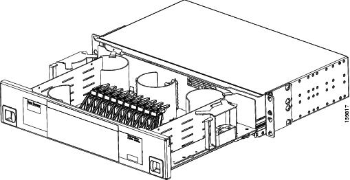
| Step 4 | On the front of the fiber-storage tray (usually installed below the node you are fibering), push the tabs on the left and right sides inward to release the lock on the tray. | ||
| Step 5 | Pull the fiber-storage tray away from the shelf until it is fully opened. | ||
| Step 6 | Open the fold-down door that
at the bottom of the shelf assembly to expose the cable-routing channel.
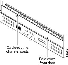 | ||
| Step 7 | Using the Cisco Transport Planner Internal Connections Report, connect one end of the fiber cable plug into the Origination Position. | ||
| Step 8 | Route the fiber cable on the card faceplate through the fiber clip on the faceplate, if provided. (Fiber clips are factory-attached to the faceplates of 32DMX, OSCM, OSC-CSM, OPT-PRE, OPT-BST, OPT-BST-E, OPT-BST-L, OPT-AMP-L, OPT-AMP-17-C, OPT-AMP-C, OPT-RAMP-C, OPT-RAMP-CE, OPT-EDFA-17, OPT-EDFA-24, and OPT-EDFA-35 cards.) | ||
| Step 9 | Route the fiber cable through the cable-routing channel and cutout on the appropriate side of the shelf assembly, as necessary. | ||
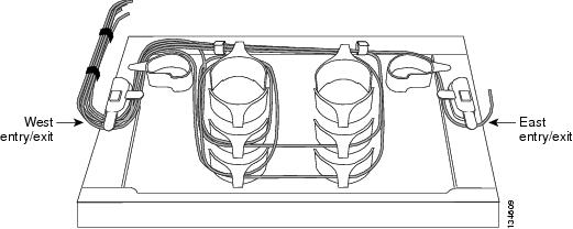
| Step 10 | As needed, route slack
fiber-optic cable around the round cable retainers in the fiber-storage tray.
| ||
| Step 11 | Route the fiber cable out either side of the fiber-storage tray as necessary. | ||
| Step 12 | Plug the other end of the
cable into the Destination position.
| ||
| Step 13 | Repeat Steps 4 through 12 until you have connected the intra-shelf fibers according to the Cisco Transport Planner Internal Connections report. | ||
| Step 14 | To close the fiber-storage
tray, push the tray back toward the rack until it locks into place.
Stop. You have completed this procedure. |
DLP-G349 Using the Cisco Transport Planner Internal Connections Report
|
This task describes how to use the Cisco Transport Planner Internal Connections report to install cables on the DWDM cards. |
|
|
NTP-G31 Installing the DWDM Dispersion Compensating Units
|
|
| Step 1 | Display the Cisco Transport
Planner Internal Connections report for the node that you are provisioning. The
Internal Connections report is presented in two views, a patchcord installation
view and a software provisioning view. The
Patchcord installation
view lists all the patchcord connections that the installer has to
mechanically cable within the site between the different ports of the DWDM
cards. The
SW Provisioning
view contains all the connections to be manually set or removed via
CTC with respect to the default connections that are automatically generated by
the system software running on the node.
The tables identify the patchcords that you must cable by their endpoints. Starting from the left side of report, Position identifies the fiber origination point. The location shown in the next Position to right is the destination point for the fiber connection. The patchcord endpoints are identified by site, assembly shelf, slot, and port number. Information provided by the Internal Connections Software report includes:
| ||||
| Step 2 | Return to your originating procedure (NTP). |
NTP-G140 Installing Fiber-Optic Cables Between Terminal, Hub, or ROADM Nodes
|
This procedure routes fiber-optic cables from the DWDM optical cards in a terminal, hub, or ROADM node to the patch panel, and from the patch panel to TXP, MXP, GE_XP, 10GE_XP, GE_XPE, 10GE_XPE, or ADM-10G cards. |
|
|
|
| Step 1 | Determine which type of node
you are fibering.
The following node types require the listed equipment. The cards and patch panels should already be installed before you begin this procedure.
| ||
| Step 2 | On the front of the patch panel tray, push the tabs on the left and right sides inward to release the lock on the tray. | ||
| Step 3 | Pull the patch
panel tray away from the shelf until it is fully opened.
| ||
| Step 4 | Depending on the
type of patch panel tray you are using:
| ||
| Step 5 | To close the
patch panel tray, unlock it by pressing the red latch in the top left corner,
and then push the tray back toward the rack until it locks into place.
Stop. You have completed this procedure. |
DLP-G315 Installing Fiber-Optic Cables From the 32WSS/32DMX Cards to the Standard Patch Panel Tray
|
This task describes how to route fiber-optic cables from 32WSS, and 32DMX cards in a terminal, hub, or ROADM node to the standard patch panel. |
|
|
The following node types require the following equipment. The cards and patch panels should already be installed before you begin this procedure.
|
|
|
NTP-G34 Installing Fiber-Optic Cables on DWDM Cards and DCUs |
|
Note | For a ROADM or hub node, two patch panels will be used, one for Side B side and one for Side A. The Side B 32WSS/32DMX card will connect to the Side B patch panel. The Side A 32WSS/32DMX card will connect to the Side A patch panel. |
| Step 1 | Choose either the Side B or Side A to cable the 32WSS and 32DMX cards for a ROADM node | ||
| Step 2 | On the patch panel, pull up
firmly on the two latches and use them to slide the patch panel up until it
snaps in place above the tray.
 | ||
| Step 3 | At the 32WSS card in the node, plug the MPO connector of an MPO cable into the
top Add RX (30.3–36.6) port of the card. If you are connecting a subsequent MPO
cable, plug the MPO connector into the first vacant Add RX card port below the
last MPO cable that was installed.
 | ||
| Step 4 | Route the
MPO cable slack through the patch panel tray as necessary.
| ||
| Step 5 | While facing the front of the
patch panel, at the rear side of the patch panel, plug the eight LC-connector
fan-out cables on the MPO cable into their corresponding connectors on the
bottom row of the patch panel. You should plug the fan-out cables from left to
right (as you face the patch panel), following the numbers tagged (1 through 8)
on the cables.
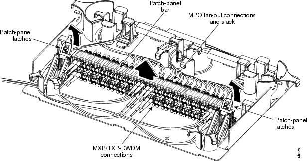
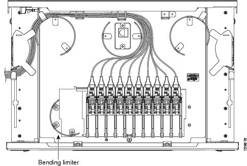
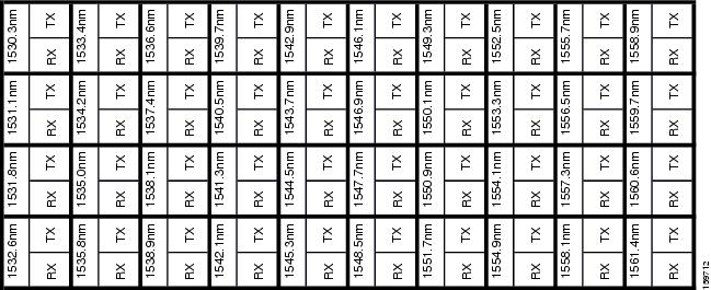
The following figure shows the patch panel connectors from the rear of the patch panel tray. 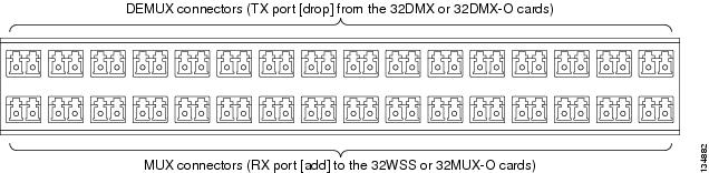 The following figure shows the assigned wavelengths for each port on the patch panel, as indicated at the top of the patch panel bar. The numbers on the patch panel bar correspond to a wavelength on the ITU grid.  | ||
| Step 6 | As necessary, repeat Steps 3 through 5 for the remaining three Add RX ports on the 32WSS card, until all 32 LC connectors on the bottom row of the rear of the patch panel are connected. | ||
| Step 7 | At the adjacent 32DMX card in the same side of the shelf, plug the MPO connector of an MPO cable into the top Drop TX (30.3–36.6) port of the 32DMX card. If you are connecting a subsequent MPO cable, plug the MPO connector into the first vacant Drop TX card port below the last MPO cable that was installed. | ||
| Step 8 | Route the MPO cable slack
through the patch panel tray as necessary.
| ||
| Step 9 | While facing the front of the patch panel, at the rear of the patch panel, plug the eight LC-connector fan-out cables on the MPO cable into their corresponding connectors on the top row of the patch panel. You should plug the fan-out cables from left to right (as you face the patch panel), following the numbers tagged (1 through 8) on the cables. | ||
| Step 10 | As necessary, repeat Steps 7 through 9 for the remaining three Drop TX ports on the 32DMX card, until all 32 LC connectors on the top row of the rear of the patch panel are connected. | ||
| Step 11 | For a hub or ROADM node, repeat Steps 2 through 10 to cable the other side of the shelf to the second patch panel. For a terminal node, go to Step 12. | ||
| Step 12 | Return to your originating procedure (NTP). |
DLP-G316 Installing Fiber-Optic Cables from TXP, MXP Cards to the Standard Patch Panel Tray
|
This task describes how to route fiber-optic cables from the patch panel to TXP, MXP, GE_XP, 10GE_XP, GE_XPE, 10GE_XPE, ADM-10G, or OTU2_XP cards. |
|
|
TXP, MXP, GE_XP, 10GE_XP, GE_XPE, 10GE_XPE, ADM-10G, or OTU2_XP card(s) |
|
|
NTP-G34 Installing Fiber-Optic Cables on DWDM Cards and DCUs |
|
| Step 1 | At the appropriate TXP, MXP, GE_XP, 10GE_XP, GE_XPE, 10GE_XPE, ADM-10G, or OTU2_XP card, plug one end of a fiber-optic cable into the TX port of the DWDM adapter. | ||
| Step 2 | As needed, route slack
fiber-optic cable around the round cable retainers in the fiber-storage tray.
| ||
| Step 3 | On the DWDM (front) side of
the patch panel, plug the other end of the cable into the connector on the
bottom row that corresponds to the wavelength to which the TXP, MXP, GE_XP,
10GE_XP, GE_XPE, 10GE_XPE, ADM-10G, or OTU2_XP port is tuned.
The following figure shows the patch panel connectors from the front of the patch panel tray. 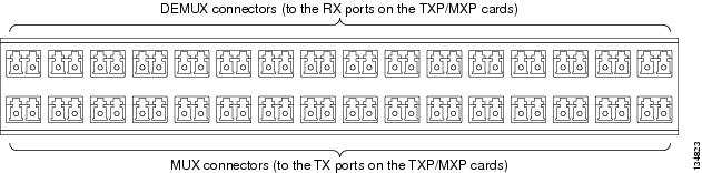 | ||
| Step 4 | Plug one end of a fiber-optic cable into the RX port of the DWDM adapter on the TXP, MXP, GE_XP, 10GE_XP, GE_XPE, 10GE_XPE, ADM-10G, or OTU2_XP card. | ||
| Step 5 | On the DWDM (front) side of the patch panel, plug the other end of the cable into the connector on the top row that corresponds to the wavelength to which the TXP, MXP, GE_XP, 10GE_XP, GE_XPE, 10GE_XPE, ADM-10G, or OTU2_XP card is tuned. | ||
| Step 6 | Repeat Steps 1 through 5 for all of the TXP, MXP, GE_XP, 10GE_XP, GE_XPE, 10GE_XPE, ADM-10G, or OTU2_XP cards that you want to connect to this patch panel. | ||
| Step 7 | Return to your originating procedure (NTP). |
DLP-G356 Installing Fiber-Optic Cables from the 32WSS/32DMX Cards to the Deep Patch Panel Tray
|
This task describes how to route fiber-optic cables from 32WSS, and 32DMX cards in a terminal, hub, or ROADM node to the deep patch panel tray. |
|
|
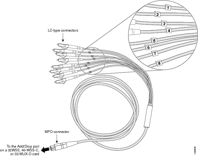
The following node types require the following equipment. The cards and patch panels should already be installed before you begin this procedure. For terminal nodes, one of the following card sets: Plus one deep patch panel tray, preinstalled with MPO cables (each MPO cable is terminated on one end with one MPO connector and on the other end with eight LC-type connectors) For hub nodes, one of the following card sets: Plus two deep patch panel trays, preinstalled with MPO cables (each MPO cable is terminated on one end with one MPO connector and on the other end with eight LC-type connectors) For ROADM nodes, one of the following card sets: Plus two deep patch panel trays, preinstalled with MPO cables (each MPO cable is terminated on one end with one MPO connector and on the other end with eight LC-type connectors) |
|
|
NTP-G34 Installing Fiber-Optic Cables on DWDM Cards and DCUs |
|
Note | For a ROADM or hub node, two patch panels will be used, one for Side A (Slots 1 through 6) and one for Side B (Slots 12 through 17). The Side B 32WSS/32DMX card will connect to the Side B patch panel. The Side A 32WSS/32DMX card will connect to the Side A patch panel. The MPO cables in the patch panel are preinstalled and routed out of the right side of the patch panel tray. |
| Step 1 | Choose either Side A or Side B of the shelf to cable the 32WSS and 32DMX cards for a ROADM node | ||
| Step 2 | On the patch panel, locate the MPO connectors (Figure 2). | ||
| Step 3 | Route the preinstalled MPO
cables out of the tray to the right or left.
 | ||
| Step 4 | At the 32WSS
card in the node, plug the MPO connector labeled 1 RX on an MPO
cable (Figure 2) into the top Add RX (30.3–36.6)
port of the card.
| ||
| Step 5 | Plug the MPO connector labeled 2-RX into the Add RX (38.1–44.5) port on the card. | ||
| Step 6 | Plug the MPO connector labeled 3-RX into the Add RX (46.1–52.5) port on the card. | ||
| Step 7 | Plug the MPO connector
labeled 4-RX into the Add RX (54.1–60.6) port on the card.
The following figure shows the deep patch panel ports and corresponding wavelengths. 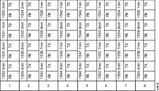 | ||
| Step 8 | At the adjacent 32DMX card in the same side of the shelf, plug the MPO connector labeled 1 TX on the MPO cable (Figure 2) into the top Drop TX (30.3–36.6) port of the card (Figure 2). | ||
| Step 9 | Plug the MPO connector labeled 2-TX into the Drop TX (38.1–44.5) port on the card. | ||
| Step 10 | Plug the MPO connector labeled 3-TX into the Drop TX (46.1–52.5) port on the card. | ||
| Step 11 | Plug the MPO connector
labeled 4-TX into the Drop TX (54.1–60.6) port on the card.
| ||
| Step 12 | For a hub or ROADM node, repeat Steps 2 through 11 to cable the other side of the shelf to the second patch panel. For a terminal node, go to Step 13. | ||
| Step 13 | Return to your originating procedure (NTP). |
DLP-G427 Rerouting Fiber-Optic Cables in the 40-Channel Patch Panel Tray
|
This task reroutes the MPO cables that are preinstalled in the 40-channel patch panel tray. The cables exit to the left when shipped; this task reroutes the cables out of the right side of the tray. Use this task when you want to connect these MPO cables to cards installed on the right side of the shelf. |
|
| Step 1 | Carefully unwind all of the
MPO cables in the patch panel tray and gently set the cables to the side of the
tray, out of the way of the internal hardware.
  |
| Step 2 | Slide each of the ten LC-port adapter packs upward. |
| Step 3 | Unscrew the two screws in the bottom left bending limiter and remove the bending limiter. |
| Step 4 | Remove the single screw below the center of the patch panel to free the patch panel hardware. |
| Step 5 | Slide the patch panel to the left, and reinstall the screw below the center of the patch panel. |
| Step 6 | Install the bending limiter to the right of the patch panel by installing the two screws. |
| Step 7 | Carefully route all of the MPO cables around the bending limiter and out the exit on the right side of the patch panel tray. |
| Step 8 | Slide each of the ten LC-port adapter packs downward. |
| Step 9 | Return to your originating procedure (NTP). |
DLP-G428 Installing Fiber-Optic Cables from the 40-WSS-C/40-WSS-CE and 40-DMX-C/40-DMX-CE Cards to the 40-Channel Patch Panel Tray
|
This task describes how to route fiber-optic cables from 40-WSS-C/40-WSS-CE and 40-DMX-C/40-DMX-CE cards in an expanded ROADM, terminal, or hub node to the 40-channel (80-port) patch panel tray (15454-PP-80). |
|
|
The following node types require the following equipment. The cards and patch panels should already be installed before you begin this procedure. Plus one 40-channel patch panel tray, preinstalled with MPO cables (each MPO cable is terminated on one end with one MPO connector and on the other end with eight LC-type connectors) Plus two 40-channel patch panel trays, preinstalled with MPO cables (each MPO cable is terminated on one end with one MPO connector and on the other end with eight LC-type connectors) |
|
|
NTP-G34 Installing Fiber-Optic Cables on DWDM Cards and DCUs DLP-G427 Rerouting Fiber-Optic Cables in the 40-Channel Patch Panel Tray |
|
Note | For a ROADM node, two patch panels will be used, one for the Side A and one for Side B. The Side B 40-WSS-C/40-WSS-CE card will connect to the Side B patch panel. The Side A 40-WSS-C/40-WSS-CE will connect to the Side A patch panel. The MPO cables in the patch panel are preinstalled and routed out of the left side of the patch panel tray. |
| Step 1 | Choose either the Side A or
Side B side of the shelf to cable the 40-WSS-C/40-WSS-CE and 40-DMX-C/40-DMX-CE
cards.
| ||
| Step 2 | On the patch panel, locate the MPO cables and connectors. | ||
| Step 3 | At the 40-WSS-C/40-WSS-CE card in the node, plug the MPO connector labeled 1 RX on an MPO cable (Figure 2) into the top Add RX (30.3–35.8) port of the card. | ||
| Step 4 | Plug the MPO connector labeled 2-RX into the Add RX (36.6–42.1) port on the card. | ||
| Step 5 | Plug the MPO connector labeled 3-RX into the Add RX (42.9–48.5) port on the card. | ||
| Step 6 | Plug the MPO connector labeled 4-RX into the Add RX (49.3–54.9) port on the card. | ||
| Step 7 | Plug the MPO connector
labeled 5-RX into the Add RX (55.7–61.4) port on the card.
| ||
| Step 8 | At the adjacent 40-DMX-C/40-DMX-CE card in the same side of the shelf, plug the MPO connector labeled 1 TX on the MPO cable into the top Drop TX (30.3–35.8) port of the card. | ||
| Step 9 | Plug the MPO connector labeled 2-TX into the Drop TX (36.6–42.1) port on the card. | ||
| Step 10 | Plug the MPO connector labeled 3-TX into the Drop TX (42.9–48.5) port on the card. | ||
| Step 11 | Plug the MPO connector labeled 4-TX into the Drop TX (49.3–54.9) port on the card. | ||
| Step 12 | Plug the MPO connector
labeled 5-TX into the Drop TX (55.7–61.4) port on the card.
| ||
| Step 13 | Repeat Steps 2 through 12 to cable the other side of the shelf to the second patch panel. | ||
| Step 14 | Return to your originating procedure (NTP). |
DLP-G357 Installing Fiber-Optic Cables from the TXP, MXP Cards to the Deep Patch Panel Tray or 40-Channel Patch Panel Tray
|
This task describes how to route fiber-optic cables from the deep patch panel (32-channel) or 40-channel patch panel to TXP, MXP, GE_XP, 10GE_XP, GE_XPE, 10GE_XPE, ADM-10G, or OTU2_XP cards. |
|
|
TXP, MXP, GE_XP, 10GE_XP, GE_XPE, 10GE_XPE, ADM-10G, or OTU2_XP card(s) Deep (32-channel) patch panel tray or 40-channel patch panel tray |
|
|
NTP-G34 Installing Fiber-Optic Cables on DWDM Cards and DCUs |
|
| Step 1 | Refer to the Cisco Transport Planner Internal Connections Report to connect the TXP, MXP, GE_XP, 10GE_XP, GE_XPE, 10GE_XPE, ADM-10G, or OTU2_XP card to the proper (Side A or Side B) patch panel. At the appropriate TXP, MXP, GE_XP, 10GE_XP, GE_XPE, 10GE_XPE, ADM-10G, or OTU2_XP card, plug one end of a fiber-optic cable into the TX port of the DWDM adapter. | ||
| Step 2 | As needed, route slack
fiber-optic cable around the round cable retainers in the fiber-storage tray.
| ||
| Step 3 | Plug the other end of the cable into the RX connector on the patch panel that corresponds to the wavelength to which the TXP, MXP, GE_XP, 10GE_XP, GE_XPE, 10GE_XPE, ADM-10G, or OTU2_XP port is tuned. (See Figure 2 for a view of the wavelengths assigned to the deep patch panel connectors or Figure 1 for a view of the wavelengths assigned to the 40-channel patch panel connectors). | ||
| Step 4 | On the patch panel tray, slide each of the ten LC-port adapter packs upward. | ||
| Step 5 | Plug one end of a fiber-optic cable into the RX port of the DWDM adapter on the TXP, MXP, GE_XP, 10GE_XP, GE_XPE, 10GE_XPE, ADM-10G, or OTU2_XP card. | ||
| Step 6 | Plug the other end of the cable into the TX connector on the patch panel that corresponds to the wavelength to which the TXP, MXP, GE_XP, 10GE_XP, GE_XPE, 10GE_XPE, ADM-10G, or OTU2_XP port is tuned. | ||
| Step 7 | Repeat Steps 1 through 6 for each TXP, MXP, GE_XP, 10GE_XP, GE_XPE, 10GE_XPE, ADM-10G, or OTU2_XP card that you want to connect to this patch panel. | ||
| Step 8 | Return to your originating procedure (NTP). |
DLP-G530 Installing Fiber-Optic Cables from the 40-SMR1-C, 40-SMR2-C, or 80-WXC-C Cards to the 15216-MD-40 or 15216-MD-48 Patch Panel Tray
|
Purpose |
This task describes how to route fiber-optic cables from the 40-SMR1-C1, 40-SMR2-C1, or 80-WXC-C2 cards in a ROADM, terminal, or hub node to the 15216-MD-40 or 15216-MD-48 patch panel tray. |
|
Tools/Equipment |
The following node types require the following equipment. The cards and patch panels should already be installed before you begin this procedure. Terminal nodes:
Hub nodes:
ROADM nodes: |
|
Prerequisite Procedures |
Install and route fiber-optic cables on the patch panel. For more information, see the required installation guide:
|
|
Required/As Needed |
As needed |
|
Onsite/Remote |
Onsite |
|
Security Level |
None |
Note | The 40-SMR1-C and 40-SMR2-C cards can be connected only to the odd patch panel (15216-MD-40-ODD, 15216-EF-40-ODD, or 15216-MD-48-ODD). The 80-WXC-C card can be connected to the odd patch panel (15216-MD-40-ODD, 15216-EF-40-ODD, or 15216-MD-48-ODD) and the even patch panel (15216-MD-40-EVEN, 15216-EF-40-EVEN, or 15216-MD-48-EVEN) in the presence of interleaver and deinterleaver pluggable (15216-MD-ID-50 or 15216-MD-48-CM). |
Note | For optical interconnections between the odd patch panel, interleaver and deinterleaver module, and the even patch panel, see the “Installing Cisco ONS 15216-MD-ID-50 Optical Interleaver and Deinterleaver Pluggable” or “Installing the Cisco ONS 15216-MD-48-CM Interleaver and Deinterleaver Pluggable” guide. |
Note | For a ROADM node, two patch panels will be used, one for the Side A (Slots 1 through 6) and one for Side B (Slots 12 through 17). The Side B 40-SMR1-C or 40-SMR2-C card will connect to the Side B patch panel. The Side A 40-SMR1-C or 40-SMR2-C will connect to the Side A patch panel. |
| Step 1 | Choose Side A or Side B of the shelf to route the cables from the 40-SMR1-C, 40-SMR2-C, or 80-WXC-C card. | ||
| Step 2 | On the 15216 patch panel, locate the COM TX port and insert one end of an LC-LC cable. | ||
| Step 3 | Route the LC-LC cable through the 15216 patch panel to the 40-SMR1-C card, 40-SMR2-C card, or 80-WXC-C card on Side A of the node. | ||
| Step 4 | Connect the other end of the LC-LC cable to the ADD RX port on the 40-SMR1-C or 40-SMR2-C cards or the AD port on the 80-WXC-C card. | ||
| Step 5 | On the 15216 patch panel, locate the COM RX port and insert one end of an LC-LC cable. | ||
| Step 6 | Route the LC-LC cable through the 15216 patch panel to the 40-SMR1-C, 40-SMR2-C or 80-WXC-C card on Side A of the node. | ||
| Step 7 | Connect the other end of the
LC-LC cable to the DROP TX port on the 40-SMR1-C, 40-SMR2-C, or 80-WXC-C card.
| ||
| Step 8 | For a hub or
ROADM node, repeat Steps 2 through 7 to cable the other side of the shelf to
the second patch panel. For a terminal node, go to Step 9.
| ||
| Step 9 | Return to your originating procedure (NTP). |
NTP-G185 Installing Fiber-Optic Cables between Mesh Nodes
|
This procedure describes how to install fiber-optic cables to create mesh nodes. You must route fiber-optic cables from:
|
|||
|
Mesh nodes require the following equipment. The cards and patch panels should already be installed before you begin this procedure.
|
|||
|
NTP-G34 Installing Fiber-Optic Cables on DWDM Cards and DCUs DLP-G427 Rerouting Fiber-Optic Cables in the 40-Channel Patch Panel Tray |
|||
| Step 1 | Open the patch panel tray:
| ||
| Step 2 | Complete the DLP-G430 Installing Fiber-Optic Cables from the 40-MUX-C and 40-DMX-C Cards to the 40-Channel Patch Panel Tray. | ||
| Step 3 | Complete the DLP-G431 Installing Fiber-Optic Cables from the 40-WXC-C, or 40-SMR2-C Cards to a Mesh Patch Panel Tray. | ||
| Step 4 | Close the patch
panel tray:
Stop. You have completed this procedure. |
DLP-G430 Installing Fiber-Optic Cables from the 40-MUX-C and 40-DMX-C Cards to the 40-Channel Patch Panel Tray
|
This task describes how to route fiber-optic cables from 40-MUX-C and 40-DMX-C cards in mesh node to the 40-channel (80-port) patch panel tray (15454-PP-80). In a mesh node, one 40-channel patch panel tray is required for each direction. The Side A 40-MUX-C and 40-DMX-C cards will connect to the Side A 40-channel patch panel. The Side B 40-MUX-C and 40-DMX-C cards will connect to the Side B 40-channel patch panel, and so forth, up to a maximum of an eight-degree mesh node (Sides A through H). |
|
|
The cards and patch panels should already be installed before you begin this procedure. |
|
|
NTP-G34 Installing Fiber-Optic Cables on DWDM Cards and DCUs DLP-G427 Rerouting Fiber-Optic Cables in the 40-Channel Patch Panel Tray |
|
| Step 1 | Choose Side A of the shelf to
cable the 40-MUX-C and 40-DMX-C cards.
| ||
| Step 2 | On the patch panel, locate the MPO cables and connectors. | ||
| Step 3 | At the 40-MUX-C card in the node, plug the MPO connector labeled 1 RX on an MPO cable into the top Add RX (30.3–35.8) port of the card. | ||
| Step 4 | Plug the MPO connector labeled 2-RX into the Add RX (36.6–42.1) port on the card. | ||
| Step 5 | Plug the MPO connector labeled 3-RX into the Add RX (42.9–48.5) port on the card. | ||
| Step 6 | Plug the MPO connector labeled 4-RX into the Add RX (49.3–54.9) port on the card. | ||
| Step 7 | Plug the MPO connector labeled 5-RX into the Add RX (55.7–61.4) port on the card. | ||
| Step 8 | At the adjacent 40-DMX-C card in the same side of the shelf, plug the MPO connector labeled 1 TX on the MPO cable. | ||
| Step 9 | Plug the MPO connector labeled 2-TX into the Drop TX (36.6–42.1) port on the card. | ||
| Step 10 | Plug the MPO connector labeled 3-TX into the Drop TX (42.9–48.5) port on the card. | ||
| Step 11 | Plug the MPO connector labeled 4-TX into the Drop TX (49.3–54.9) port on the card. | ||
| Step 12 | Plug the MPO connector
labeled 5-TX into the Drop TX (55.7–61.4) port on the card.
| ||
| Step 13 | Repeat Steps 2 through 12 for the remaining sides of the mesh node (Sides B through H, depending on the type of mesh node you want to cable). | ||
| Step 14 | Return to your originating procedure (NTP). |
DLP-G431 Installing Fiber-Optic Cables from the 40-WXC-C, or 40-SMR2-C Cards to a Mesh Patch Panel Tray
|
This task connects fiber-optic cables from the 40-WXC-C or 40-SMR2-C cards in a mesh node to the 4-degree (PP-MESH-4 or 15454-PP-4-SMR) or 8-degree (PP-MESH-8) mesh patch panel. The four-degree patch panel allows up to 4 sides to be used per node, while the eight-degree patch panel allows up to 8 sides to be used per node. |
|||
|
The cards and patch panel trays should already be installed before you begin this procedure.
|
|||
|
|||
| Step 1 | Choose Side A of the shelf to cable the 40-WXC-C, or 40-SMR2-C card to the mesh patch panel. | ||
| Step 2 | On the mesh patch panel, locate the EXP TX A port (for PP-MESH-4 and PP-MESH-8) or EXP-A port (for 15454-PP-4-SMR) and insert one end of an MPO-MPO cable. | ||
| Step 3 | Route the MPO cable through the mesh patch panel and out to the 40-WXC-C, or 40-SMR2-C card on Side A of the node. | ||
| Step 4 | Connect the other end of the
MPO cable to the EXP RX port on the 40-WXC-C, or EXP port on the 40-SMR2-C
card.
| ||
| Step 5 | On the PP-MESH-4 or PP-MESH-8 mesh patch panel, locate the COM RX A port and insert one end of an LC-LC cable. | ||
| Step 6 | Route the LC cable through the mesh patch panel to the 40-WXC-C card on Side A of the node. | ||
| Step 7 | Connect the other end of the LC cable to the EXP TX port on the 40-WXC-C. | ||
| Step 8 | Repeat Steps
1 through
7 as necessary to
cable Sides B through D for a 4-degree patch panel, and Sides B through H for
an 8-degree patch panel.
|
NTP-G191 Installing Fiber-Optic Cables on Passthrough ROADM Nodes
|
This procedure routes fiber-optic cables from a 32WSS card in a ROADM node in one shelf to the corresponding 32WSS card in a ROADM node in another shelf. The purpose of this routing is to connect East and West intershelf ROADMs in a passthrough configuration. |
|
|
Each ROADM node requires the listed equipment. The cards and fiber-storage trays should already be installed before you begin this procedure. |
|
|
DLP-G348 Using the Cisco Transport Planner Shelf Layout Report
|
|
| Step 1 | Choose either the East or West side of the first shelf to cable the 32WSS card for the first ROADM node. | ||
| Step 2 | Choose the corresponding West or East side of the second shelf to cable the 32WSS card for the second ROADM node. | ||
| Step 3 | On the front of the fiber-storage tray that will be used for routing the fiber-optic cable, push the tabs on the left and right sides inward to release the lock on the tray. | ||
| Step 4 | Pull the fiber-storage tray away from the shelf until it is fully opened. | ||
| Step 5 | Open the fold-down door
located at the bottom of both shelf assemblies to expose the cable-routing
channels for each.
| ||
| Step 6 | Plug one end of the first 3-meter fiber-optic cable into the EXP-TX connector on the first 32WSS card. | ||
| Step 7 | Route the fiber-optic cable through the shelf cable-routing channel and cutout on the appropriate side of the shelf assembly, as necessary. | ||
| Step 8 | Route the fiber-optic cable through the vertical fiber guide as needed to reach the entry to the fiber-storage tray. | ||
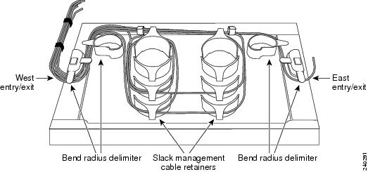
| Step 9 | Thread the cable into the fiber-storage tray at the appropriate side and around the first bend radius delimiter as shown in Figure 2. | ||
| Step 10 | As needed, route slack
fiber-optic cable around the slack management cable retainers in the
fiber-storage tray.
| ||
| Step 11 | Thread the fiber cable through the second bend delimiter and out the appropriate side of the fiber-storage tray as necessary. | ||
| Step 12 | Route the fiber-optic cable through the vertical fiber guide as needed to reach the second ROADM shelf where the second 32WSS is located. | ||
| Step 13 | Route the fiber-optic cable through the shelf cutout and through the shelf cable routing channel as needed. | ||
| Step 14 | Plug the end of the 3-meter fiber-optic cable into the EXP-RX port of the second 32WSS card. | ||
| Step 15 | Plug one end of the second 3-meter fiber-optic cable into the EXP-TX connector on the second 32WSS card. | ||
| Step 16 | Follow Step 7 through Step 14 to connect the EXP-TX connector of the second 32WSS card to the EXP-RX port of the first 32WSS card. | ||
| Step 17 | Close the fold-down doors
located at the bottom of both shelf assemblies and slide the fiber-storage tray
back into its normal locked position.
Stop. You have completed this procedure. |
NTP-G141 Installing Fiber-Optic Cables for Y-Cable Protection Modules
|
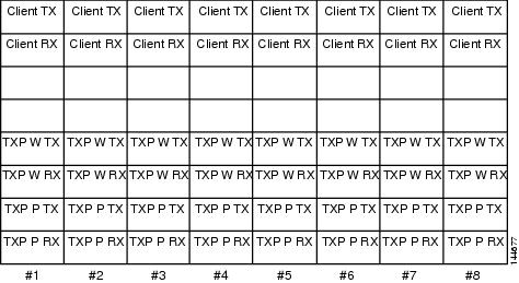
This procedure installs and routes fiber-optic cables from the client signal to the Y-cable protection module (single mode or multimode), and from the Y-cable module to the transponder node. Using one Y-cable protection module, you can protect one client signal with two TXP, MXP, AR_MXP, AR_XP, AR_XPE, GE_XP, 10GE_XP, GE_XPE, 10GE_XPE, or OTU2_XP cards, and two client signals with four TXP, MXP, GE_XP, 10GE_XP, GE_XPE, 10GE_XPE, or OTU2_XP cards. You can use Y-cable protection modules that you have installed in a FleyLayer shelf, or Y-cable modules installed in a Y-cable module tray. |
|
Note | To use Y-cable protection for GE_XP, 10GE_XP, GE_XPE, and 10GE_XPE cards, the cards must be provisioned in 10GE MXP, 20GE MXP, or 10GE TXP mode. Y-cable protection cannot be used for GE_XP, 10GE_XP, GE_XPE, and 10GE_XPE cards that are provisioned in L2-over-DWDM mode. |
| Step 1 | As needed, complete the DLP-G375 Installing Fiber-Optic Cables on the Y-Cable Modules in the FlexLayer Shelf. |
| Step 2 | As needed, complete the
DLP-G376 Installing Fiber-Optic Cables on the Y-Cable Modules in the Y-Cable Module Tray.
Stop. You have completed this procedure. |
DLP-G375 Installing Fiber-Optic Cables on the Y-Cable Modules in the FlexLayer Shelf
|
This task installs fiber-optic cables from the TXP, MXP, GE_XP, 10GE_XP, GE_XPE, 10GE_XPE, AR_MXP, AR_XP, or AR_XPE cards to the Y-cable modules installed in the FlexLayer shelves, and from the Y-cable modules to the client devices. |
|
| Step 1 | Referring to the
Cisco Transport Planner Internal Connections Report, install a fiber-optic
cable between a TXP, MXP, GE_XP, 10GE_XP, GE_XPE, 10GE_XPE, AR_MXP, AR_XP, or
AR_XPE card and a Y-cable module.
If you want to protect one client signal or protect two client signals using a single Y-cable module, connect the fiber-optic cables according to the following tables. | ||||||||||||||||||||||||||||
| Step 2 | As needed, route slack fiber-optic cable around
the round cable retainers in the fiber-storage tray as you install cables
between the Y-cable module and the TXP, MXP, GE_XP, 10GE_XP, GE_XPE, or
10GE_XPE cards (Figure 2).
| ||||||||||||||||||||||||||||
| Step 3 | Install a fiber-optic cable between the client device and the Y-cable module where you just installed a fiber-optic cable to the TXP, MXP, GE_XP, 10GE_XP, GE_XPE, or 10GE_XPE card. | ||||||||||||||||||||||||||||
| Step 4 | Repeat Steps 1 through 3 for each Y-cable module you need to use for Y-cable protection. | ||||||||||||||||||||||||||||
| Step 5 | Return to your originating procedure (NTP). |
DLP-G376 Installing Fiber-Optic Cables on the Y-Cable Modules in the Y-Cable Module Tray
|
This task installs fiber-optic cables from the TXP, MXP, GE_XP, 10GE_XP, GE_XPE, or 10GE_XPE cards to the Y-cable modules installed in the Y-cable module tray, and from the Y-cable modules to the client devices. |
|
|
Fiber-optic cables (4-meter [13.12-foot]), single-mode or multimode as appropriate |
|
| Step 1 | Open the drawer of the tray by pushing inward on the latches located at the left and right front of the tray. | ||||||
| Step 2 | On each Y-cable module you will connect, use the tab to slide the module up so that it is fully extended and easily accessible in the tray. | ||||||
| Step 3 | Referring to the
Cisco Transport Planner Internal Connections Report, install a 4-meter
(13.12-foot) fiber-optic cable (single-mode or multimode, as appropriate)
between a TXP, MXP, GE_XP, 10GE_XP, GE_XPE, or 10GE_XPE card and the Y-cable
module installed farthest to the left. Proceed according to the port label
affixed to the front of the tray to identify the ports on each installed
module.
As needed, route slack fiber-optic cable around the round cable retainers in theY-cable module tray as you install cables between the Y-cable module and the TXP, MXP, GE_XP, 10GE_XP, GE_XPE, or 10GE_XPE card as shown in the following figure. 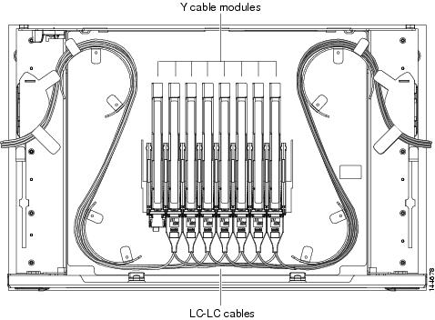
| ||||||
| Step 4 | Referring to the Cisco Transport Planner Internal Connections Report, install a fiber-optic cable of adequate length (single-mode or multimode, as appropriate) between the Y-cable module and the client signal that you want to protect. | ||||||
| Step 5 | As needed, route slack fiber-optic cable around the round cable retainers in theY-cable module tray as you install cables between the Y-cable module and the TXP, MXP, GE_XP, 10GE_XP, GE_XPE, or 10GE_XPE card. | ||||||
| Step 6 | Repeat Steps 2 to 5 for each Y-cable module you need to use for Y-cable protection. | ||||||
| Step 7 | To close the tray, unlock the drawer from the open position by depressing the red lock at the back left of the tray and push the tray closed. | ||||||
| Step 8 | Return to your originating procedure (NTP). |
NTP-G39 Verifying OSCM Transmit Power
|
This procedure verifies that the transmit power for the ONS 15454 OSCM and the OSC-CSM cards is correct. |
|
| Step 1 | Disable automatic laser shutdown (ALS) on Side A or (for terminal nodes) the terminal side OSCM or OSC-CSM card: |
| Step 2 | If an OSC-CSM or OSCM card is installed on Side B, complete the following steps. If not, continue with Step 3. |
| Step 3 | Complete the DLP-G314 Verifying OSCM Transmit Power. |
| Step 4 | Change ALS to Auto Restart on the Side A or (for terminal nodes) the terminal side OSCM or OSC-CSM card: |
| Step 5 | If an OSC-CSM or OSCM card is
installed on Side B, complete the following steps. If not, you have completed
this procedure.
|
DLP-G314 Verifying OSCM Transmit Power
|
This task verifies that the transmit power of the OSCM card is correct. |
|
| Step 1 | Display the OSCM card in card view. |
| Step 2 | Click the tabs. |
| Step 3 | Record the Port 3 (OSC TX) Power value: _____. |
| Step 4 | Change to node view (single-shelf mode) or multishelf view (multishelf mode), then click the tabs. |
| Step 5 | Record the OSC Power value under the OSCM card in the tree view. |
| Step 6 | If the power value recorded
in
Step 3 is not within
the range of +/– 0.5 dBm recorded in
Step 5, complete the
following steps. Otherwise, continue with
Step 7.
|
| Step 7 | Return to your originating procedure (NTP). |
NTP-G210 Provisioning Node for SNMPv3
| Step 1 | In node view, click the tabs. | ||||
| Step 2 | Complete the following tasks
as required:
|
NTP-G211 Provisioning Node to Send SNMPv3 Traps
| Step 1 | In node view, click the tabs. |
| Step 2 | Complete the following tasks
as required:
|
NTP-G212 Manually Provisioning a GNE/ENE to Manage an ENE using SNMPv3
|
This procedure describes how to manually configure a GNE/ENE to allow the NMS to manage an ENE using SNMPv3. |
|
| Step 1 | Go to network view. |
| Step 2 | Double-click the ENE. |
| Step 3 | Click and note the context engine ID. The is required in Step 7. |
| Step 4 | Double-click the GNE. |
| Step 5 | Complete the DLP-G496 Creating an SNMPv3 User to create an SNMPv3 user on the GNE. |
| Step 6 | Complete the following tasks as needed on the ENE: |
| Step 7 | Complete the
DLP-G502 Manually Configuring the SNMPv3 Proxy Forwarder Table. Use the context engine ID from
Step 3, the local user
details created in
Step 5, and the remote
user created in
Step 6.
Stop. You have completed this procedure. |
NTP-G213 Automatically Provisioning a GNE to Manage an ENE using SNMPv3
|
This procedure describes how to automatically configure a GNE to allow an NMS to manage an ENE using SNMPv3. |
|
| Step 1 | Go to network view. | ||
| Step 2 | Double-click the GNE. | ||
| Step 3 | Complete the DLP-G496 Creating an SNMPv3 User to create an SNMPv3 user on the GNE. | ||
| Step 4 | Complete the
DLP-G503 Automatically Configuring the SNMPv3 Proxy Forwarder Table.
Use the GNE user that you defined in
Step 3 when you
configure the Proxy Forwarder table.
|
NTP-G214 Manually Provisioning a GNE/ENE to Send SNMPv3 Traps using SNMPv3
|
This procedure describes how to manually configure the GNE/ENE to allow an ENE to send SNMPv3 traps to the NMS. |
|
| Step 1 | Go to network view. |
| Step 2 | Double-click the GNE. |
| Step 3 | Complete the DLP-G496 Creating an SNMPv3 User to create an SNMPv3 user on the GNE. |
| Step 4 | On the GNE, complete the DLP-G499 Configure SNMPv3 Trap Destination. The target IP address must be the IPv4 or IPv6 address of the NMS. For the UDP Port number, use the port number on which the NMS is listening for traps. Use the user name configured in Step 3. Also, specify a target tag name. |
| Step 5 | Double-click the ENE. |
| Step 6 | Complete the DLP-G496 Creating an SNMPv3 User to create an SNMPv3 user on the ENE. |
| Step 7 | Complete the following tasks
as required:
|
| Step 8 | On the ENE, complete the DLP-G499 Configure SNMPv3 Trap Destination. The target IP address should be the IP address of the GNE. The UDP port number is 161. Use the user name configured in Step 6. |
| Step 9 | From the network view, click the tabs. |
| Step 10 | Complete the
DLP-G504 Manually Configuring the SNMPv3 Proxy Trap Forwarder Table.
The source of
the trap must be the IP address of the ENE. For the field, provide the of the
ENE. Also, you need to specify the target tag defined in
Step 4, and the
incoming user details configured in
Step 6.
Stop. You have completed this procedure. |
NTP-G215 Automatically Provisioning a GNE/ENE to Send SNMPv3 Traps Using SNMPv3
|
This procedure describes how to automatically configure the GNE/ENE to allow an ENE to send SNMPv3 traps to the NMS. |
|
| Step 1 | Go to Network View. |
| Step 2 | Double-click the GNE. |
| Step 3 | Complete the task DLP-G496 Creating an SNMPv3 User to create an SNMPv3 user on the GNE. |
| Step 4 | On the GNE, complete the
following tasks:
|
DLP-G496 Creating an SNMPv3 User
| Step 1 | In node view, click the tabs. |
| Step 2 | Click Create. |
| Step 3 | In the Create User dialog
box, enter the following information:
|
| Step 4 | Click OK to create an SNMP user. |
| Step 5 | Return to your originating procedure. |
DLP-G497 Create MIB Views
| Step 1 | In node view, click the tabs. |
| Step 2 | Click Create. |
| Step 3 | In the Create Views dialog
box, enter the following information:
|
| Step 4 | Click OK to save the information. |
| Step 5 | Return to your originating procedure. |
DLP-G498 Create Group Access
|
This procedure creates a user group and configures the access parameters for the users in the group. |
|
| Step 1 | In node view, click the tabs. | ||
| Step 2 | Click Create. | ||
| Step 3 | In the Create Group Access
dialog box, enter the following information:
| ||
| Step 4 | Click OK to save the information. | ||
| Step 5 | Return to your originating procedure . |
DLP-G499 Configure SNMPv3 Trap Destination
| "Login to CTC" in System Setup and Software Installation Guide for Cisco NCS 4000 Series | |
| Step 1 | In node view, click the tabs. |
| Step 2 | Click Create. |
| Step 3 | In the Configure SNMPv3 Trap
dialog box, enter the following information:
|
| Step 4 | Click OK to save the information. |
| Step 5 | Return to your originating procedure . |
DLP-G500 Deleting SNMPv3 Trap Destination
DLP-G501 Creating Notification Filters
| Step 1 | In node view, click the tabs. |
| Step 2 | Click Create. |
| Step 3 | In the Create Notify dialog
box, enter the following information:
|
| Step 4 | Click OK to save the information. |
| Step 5 | Return to your originating procedure (NTP). |
DLP-G502 Manually Configuring the SNMPv3 Proxy Forwarder Table
|
This procedure creates an entry in the SNMPv3 Proxy Forwarder Table. |
|
|
Login to CTC in System Setup and Software Installation Guide for Cisco NCS 4000 Series. |
|
| Step 1 | In network view, click . |
| Step 2 | In the SNMPv3 Proxy Server area, complete the following: |
| Step 3 | In the SNMPv3 Proxy Forwarder Table area, click Manual Create. |
| Step 4 | In the Manual
Configuration of SNMPv3 Proxy Forwarder dialog box, enter the following
information:
|
| Step 5 | Click OK to save the information. |
| Step 6 | Return to your originating procedure. |
DLP-G503 Automatically Configuring the SNMPv3 Proxy Forwarder Table
|
This procedure creates an entry in the SNMPv3 Proxy Forwarder Table. |
|
|
Login to CTC in System Setup and Software Installation Guide for Cisco NCS 4000 Series. |
|
| Step 1 | In network view, click tabs. | ||
| Step 2 | In the SNMPv3 Proxy Server area, complete the following: | ||
| Step 3 | In the SNMPv3 Proxy Forwarder Table area, click Auto Create. | ||
| Step 4 | In the Automatic
Configuration of SNMPv3 Proxy Forwarder dialog box, enter the following
information:
| ||
| Step 5 | Click OK to save the settings. | ||
| Step 6 | Return to your originating procedure. |
DLP-G504 Manually Configuring the SNMPv3 Proxy Trap Forwarder Table
|
This procedure creates an entry in the SNMPv3 Proxy Trap Forwarder Table. |
|
| Step 1 | In network view, click tabs. |
| Step 2 | In the SNMPv3 Proxy Server area, complete the following: |
| Step 3 | In the SNMPv3 Proxy Trap Forwarder Table area, click Manual Create. |
| Step 4 | In the Manual
Configuration of SNMPv3 Proxy Trap Forwarder dialog box, enter the following
information:
|
| Step 5 | Click OK to save the information. |
| Step 6 | Return to your originating procedure (NTP). |
DLP-G505 Automatically Configuring the SNMPv3 Proxy Trap Forwarder Table
|
This procedure creates an entry in the SNMPv3 Proxy Trap Forwarder Table automatically. |
|
|
Login to CTC in System Setup and Software Installation Guide for Cisco NCS 4000 Series. |
|
| Step 1 | In network view, click tabs. |
| Step 2 | In the SNMPv3 Proxy Server area, complete the following: |
| Step 3 | In the SNMPv3 Proxy Trap Forwarder Table area, click Auto Create. |
| Step 4 | In the Automatic
Configuration of SNMPv3 Proxy Trap Forwarder dialog box, enter the following
information:
|
| Step 5 | Click OK to save the information. |
| Step 6 | Return to your originating procedure. |
DLP-G789 Enable RSVP on an Interface
|
This procedure enables RSVP on an interface for OCH unnumbered tunnel creation. |
|
| Step 1 | In node view (single-shelf mode) or multishelf view (multishelf mode), click the tabs. |
| Step 2 | Choose the interface from the Interface drop-down list. |
| Step 3 | Click Refresh. |
| Step 4 | In the Card area, double-click the slot that you want to configure. |
| Step 5 | In the Slot drop-down, select the required controller. |
| Step 6 | Click Apply to save the information. |
| Step 7 | Return to your originating procedure (NTP). |
DLP-G790 Create a Static LMP Connection
|
This procedure creates a static LMP connection between NCS 4000 (UNI-C) and NCS 2000 (UNI-N) nodes for OCH unnumbered tunnel creation. |
|
| Step 1 | In network view, click the tabs. |
| Step 2 | Click Create. |
| Step 3 | In the
LMP Creation
pane, complete the following:
|
| Step 4 | Click Next. |
| Step 5 | In the LMP Termination pane, complete the following: |
| Step 6 | Click Next. |
| Step 7 | In the Optical Parameters pane, enter the description, label and so on (optional) and click Next. |
| Step 8 | In the Alien Wavelength pane, complete the following: |
| Step 9 | In the Alien wavelength pane, click Finish. |
| Step 10 | Return to your originating procedure (NTP). |
NTP-G355 Provisioning OTDR for TNCS-O Cards
|
This procedure describes how to provision OTDR for the TNCS-O cards. |
|
| TNCS-O cards | |
| Step 1 | Complete the DLP-G793 Configuring Common OTDR Parameters for OTDR Scan on TNCS-O Cards. |
| Step 2 | Complete the DLP-G782 Configuring OTDR Port Values on TNCS-O Cards. |
| Step 3 | Complete the DLP-G783 Provisioning OTDR Scan Recurrence on TNCS-O Cards. |
| Step 4 | Complete the
DLP-G784 Configuring Threshold Values for OTDR Scan on TNCS-O Cards.
Stop. You have completed this procedure. |
DLP-G793 Configuring Common OTDR Parameters for OTDR Scan on TNCS-O Cards
|
(Cisco NCS 2006, NCS 2015) This task lets you configure common OTDR parameters for OTDR scan on TNCS-O cards. |
|
|
|
|
Note | Each step of this procedure is optional and is not required for the OTDR scan. |
| Step 1 | In the node view, click . | ||
| Step 2 | Check the Automatic OTDR Scan at System Start-up, Fiber Cut & Repair check box if you want the OTDR scan to start automatically after the LOS alarm is raised and cleared. | ||
| Step 3 | In the OTDR Start Delay (Min) field, enter the delay (in minutes) required before the automatic OTDR scan begins. The default value is 5 mins.
| ||
| Step 4 | Check the Automatic Baseline Save on Fiber Repair check box to set an automatic OTDR scan that you configure as a baseline scan. | ||
| Step 5 | Check the Automatic OTDR Scan on Span Loss Increase check box to set an automatic OTDR scan on increase in span loss and enter the desired span loss threshold value (in dB) in the Span Loss Increase Threshold field. The default value is 2.
OTDR scan starts automatically on the fiber if the measured span loss on the fiber is greater than the threshold value configured. | ||
| Step 6 | Check the Automatic OTDR Scan on Excessive ORL from Span check box to activate an automatic OTDR scan when the configured ORL threshold value in the Baseline Thresholds tab is less than the current ORL value.
The scan is executed in Hybrid mode; however, the scan is downgraded to Fast mode if the OSC connection is not available. | ||
| Step 7 | Check the Use Absolute Threshold for OTDR Alarms check box to raise the OTDR alarms using the Absolute algorithm. The absolute threshold values will be used.
If this check box is unchecked, the OTDR alarms are raised using the Baseline algorithm.
| ||
| Step 8 | Check the Prevent Circuit Creation on Span with Outstanding OTDR Alarms check box to prevent the creation of circuit on a span that has OTDR alarms. | ||
| Step 9 | Check the Prevent Circuit Creation on Span Never Scanned check box to raise the OTDR-SCAN-NOT-COMPLETED alarm on a span that has not gone through OTDR scan in TX direction. | ||
| Step 10 | Click Apply. | ||
| Step 11 | Return to your originating procedure (NTP). |
DLP-G782 Configuring OTDR Port Values on TNCS-O Cards
|
(Cisco NCS 2006, NCS 2015) This task configures the OTDR port values on TNCS-O cards for each sector required for an OTDR scan. |
|
|
|
|
| Step 1 | In the node view, click Provisioning > WDM-ANS > OTDR > Side. | ||||||||||||||||||||||||||||||||||||||||||||||||||||||||||||||||||||||||||||||||||||
| Step 2 | Select the port to be
configured for the OTDR scan from the
OTDR
Position drop-down list.
| ||||||||||||||||||||||||||||||||||||||||||||||||||||||||||||||||||||||||||||||||||||
| Step 3 | Equipment Insertion Loss for OTDR (Display only) Displays the sum of insertion loss caused by the amplifiers and patchcords for OTDR port in each direction.
The insertion loss is also caused by the span loss on the fiber between the two nodes. | ||||||||||||||||||||||||||||||||||||||||||||||||||||||||||||||||||||||||||||||||||||
| Step 4 | In the
Config tab, for each sector, CTC displays a table
with the default values for the following columns:
| ||||||||||||||||||||||||||||||||||||||||||||||||||||||||||||||||||||||||||||||||||||
| Step 5 | Check the Enable ORL Continue Measurement on RX Direction check box to enable the Optical Return Loss (ORL) measurement in the RX direction.
ORL represents the total reflected optical power from a complete fiber link. This includes the natural backscattered power of the fiber and the reflected power coming from optical connectors, fiber splicing, or other discontinuities along the link. ORL is expressed with a positive number and defined with the following formula: ORL [dB] = P_in [dB] – P_out [dB] where P_in is the total incident power entering the fiber link and P_out is the total reflected power. Higher ORL values are desirable for the fiber because they indicate lower back reflection. For example, an ORL of 40 dB is better than 20 dB. | ||||||||||||||||||||||||||||||||||||||||||||||||||||||||||||||||||||||||||||||||||||
| Step 6 | Enter the refresh rate (in mins) for ORL measurement in the Valid Refresh Rate field.
ORL measurement in RX direction can be scheduled between 5 to 1440 minute intervals. | ||||||||||||||||||||||||||||||||||||||||||||||||||||||||||||||||||||||||||||||||||||
| Step 7 | Click Apply. | ||||||||||||||||||||||||||||||||||||||||||||||||||||||||||||||||||||||||||||||||||||
| Step 8 | Return to your originating procedure (NTP). |
DLP-G783 Provisioning OTDR Scan Recurrence on TNCS-O Cards
|
(Cisco NCS 2006, NCS 2015) This task lets you provision OTDR scan recurrence on TNCS-O cards. |
|
|
|
|
| Step 1 | In the node view, click . | ||
| Step 2 | From the OTDR Position drop-down list, select the port on which you want to provision a recurring scan. | ||
| Step 3 | Equipment Insertion Loss for OTDR (Display only) Displays the sum of insertion loss caused by the amplifiers and patchcords for OTDR port in each direction. | ||
| Step 4 | In the
Recurrence area, choose a sector for the scan from
the
Sector drop-down list.
| ||
| Step 5 | Choose
Enable to schedule a recurring OTDR scan on the
selected port, or choose
Disable to disable a recurring scan on the port. If
you select
Enable, go to
Step 5.
If you select
Disable, go to
Step 9.
| ||
| Step 6 | Select the direction of the
scan from the
Direction drop-down list. The available directions
for the scan are:
| ||
| Step 7 | In the
Recurrence Type
area, choose the type of scan to be performed.
The available recurrence types are: | ||
| Step 8 | Select the
desired values from the Day, Hours, and Min drop-down lists to schedule a
periodic scan.
| ||
| Step 9 | Select the
desired values from the Day, Hours, and Min drop-down lists to schedule a delta
scan.
| ||
| Step 10 | Click Apply. | ||
| Step 11 | Return to your originating procedure (NTP). |
DLP-G784 Configuring Threshold Values for OTDR Scan on TNCS-O Cards
|
(Cisco NCS 2006, NCS 2015) This task configures the threshold values for OTDR scan on TNCS-O cards. |
|
|
|
|
| Step 1 | In the node view, click . | ||||||||||||||||||||||||||||||||||||||||||||||||||||||
| Step 2 | From the OTDR Position drop-down list, select the port to be configured with threshold values. | ||||||||||||||||||||||||||||||||||||||||||||||||||||||
| Step 3 | Equipment Insertion Loss for OTDR (Display only) Displays the sum of insertion loss caused by the amplifiers and patchcords for OTDR port in each direction. | ||||||||||||||||||||||||||||||||||||||||||||||||||||||
| Step 4 | Choose a sector from the
Sector drop-down list.
The default Loss Threshold and Reflection Threshold values for the corresponding sector are displayed in CTC. You can also configure these thresholds.
For more information on the OTDR alarms, see Cisco NCS 2000 Series Troubleshooting Guide, Release 10.x.x | ||||||||||||||||||||||||||||||||||||||||||||||||||||||
| Step 5 | Enter the absolute ORL threshold values in the TX and RX directions.
| ||||||||||||||||||||||||||||||||||||||||||||||||||||||
| Step 6 | Click Apply. | ||||||||||||||||||||||||||||||||||||||||||||||||||||||
| Step 7 | Return to your originating procedure (NTP). |
 Feedback