Introduction
 Note |
Starting with Release 11.1.4, ONS 15454 M12 chassis and TCC3 card are not supported on the ONS 15454 DWDM and WSON software packages. You must not attempt to upgrade ONS 15454 M12 nodes from a previous release to Release 11.1.4. |
This document describes Cisco Transport Controller (CTC) alarm and threshold crossing alert (TCA) monitoring and management. To troubleshoot specific alarms, refer to the Cisco ONS 15454 DWDM Troubleshooting Guide and Cisco NCS 2000 Series Troubleshooting Guide.
CTC detects and reports alarms generated by the Cisco ONS 15454 and the Optical Networking System (ONS), and Network Convergence System (NCS). You can use CTC to monitor and manage alarms at card, node, or network level. You can also view alarm counts on the LCD front panel.
Note |
Cisco ONS 15454 M2 chassis has reached its end-of-life status. For more information, see the Retirement Notification page. |
Note |
The procedures and tasks described in this document for the Cisco ONS 15454 platform is applicable to the Cisco ONS 15454 M2 and Cisco ONS 15454 M6 platforms, unless noted otherwise. |
Note |
The procedures and tasks described in this document for the Cisco NCS platform is applicable to the Cisco NCS 2002 and Cisco NCS 2006 platforms, unless noted otherwise. |
Note |
Unless otherwise specified, “ONS 15454” refers to both ANSI and ETSI shelf assemblies. |
This document includes the following topics.
Overview
CTC detects and reports alarms generated by the Cisco ONS 15454, Cisco NCS and the larger network. You can use CTC to monitor and manage alarms at the card, node, or network level. Default alarm severities conform to the Telcordia GR-474-CORE standard, but you can set alarm severities in customized alarm profiles or suppress CTC alarm reporting. For a detailed description of the standard Telcordia categories employed by Optical Networking System (ONS) and Network Convergence System(NCS) nodes, refer to the Cisco ONS 15454 DWDM Troubleshooting Guide and Cisco NCS 2000 Series Troubleshooting Guide.
Note |
ONS 15454 and NCS alarms can also be monitored and managed through Transaction Language One (TL1) or a network management system (NMS). |
Alarm Counts on the LCD for a Node, Slot, or Port
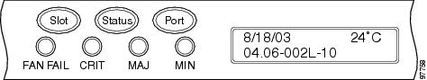
You can view node, slot, or port-level alarm counts and summaries using the buttons on the ONS 15454 and NCS LCD panels. The Slot and Port buttons toggle between display types; the Slot button toggles between node display and slot display, and the Port button toggles between slot and port views. Pressing the Status button after you choose the display mode changes the display from alarm count to alarm summary.
The ONS 15454 and NCS have a one-button update for some commonly viewed alarm counts. If you press the Slot button once and then wait eight seconds, the display automatically changes from a slot alarm count to a slot alarm summary. If you press the Port button to toggle to port-level display, you can use the Port button to toggle to a specific slot and to view each port’s port-level alarm count. The following figure shows the LCD panel layout.
Note |
In the ONS 15454 M2 and NCS 2002 shelf assembly, the LCD panel and the Slot, Port, and Status buttons are present on the fan-tray assembly. In the ONS 15454 M6 and NCS 2006 shelf assembly, the LCD is a separate unit installed above the external connection unit (ECU) and ECU2; the Slot, Port, and Status buttons are present on the LCD unit. |
Alarm Display
In the card, node, or network CTC view, click the Alarms tab to display the alarms for that card, node, or network. The Alarms window shows alarms in compliance with Telcordia GR-253-CORE. This means that if a network problem causes two alarms, such as loss of frame (LOF) and loss of signal (LOS), CTC only shows the LOS alarm in this window because it supersedes the LOF and replaces it.
The Path Width column in the Alarms and Conditions tabs expands on the alarmed object information contained in the access identifier (AID) string (such as “STS-4-1-3”) by giving the number of STSs contained in the alarmed path. For example, the Path Width tells you whether a critical alarm applies to an STS1 or an STS48c. The column reports the width as a 1, 3, 6, 12, 48, etc. as appropriate, understood to be “STS-N.”
The following table lists the column headings and the information recorded in each column.
|
Column |
Information Recorded |
|
Num |
Sequence number of the original alarm. (The column is hidden by default; to view it, right-click a column and choose Show Column > Num.) |
|
Ref |
Reference number of the original alarm. (The column is hidden by default; to view it, right-click a column and choose Show Column > Ref.) |
|
New |
Indicates a new alarm; to change this status, click either the Synchronize button or the Delete Cleared Alarms button. |
|
Date |
Date and time of the alarm. |
|
Node |
Shows the name of the node where the condition or alarm occurred. (Visible in network view.) |
|
Object |
TL1 access identifier (AID) for the alarmed object; for an STSmon or VTmon, this is the monitored STS or VT. |
|
Eqpt Type |
If an alarm is raised on a card, the card type in this slot. |
|
Slot |
If an alarm is raised on a card, the slot where the alarm occurred [appears only in network and node view (single-shelf mode) or shelf view (multishelf mode)]. |
|
Port |
If an alarm is raised on a card, the port where the alarm is raised; for STSTerm and VTTerm, the port refers to the upstream card it is partnered with. |
|
Path Width |
Indicates how many STSs are contained in the alarmed path. This information complements the alarm object notation, which is explained in the Cisco ONS 15454 DWDM Troubleshooting Guide and Cisco NCS 2000 Series Troubleshooting Guide. |
|
Sev |
Severity level: CR (Critical), MJ (Major), MN (minor), NA (Not Alarmed), NR (Not Reported). |
|
ST |
Status: R (raised), C (clear), T (transient). |
|
SA |
When checked, indicates a service-affecting alarm. |
|
Cond |
The error message/alarm name; these names are alphabetically defined in the Cisco ONS 15454 DWDM Troubleshooting Guide and Cisco NCS 2000 Series Troubleshooting Guide. |
|
Description |
Description of the alarm. |
The following table lists the color codes for alarm and condition severities.
|
Color |
Description |
|
Red |
Raised Critical (CR) alarm |
|
Orange |
Raised Major (MJ) alarm |
|
Yellow |
Raised Minor (MN) alarm |
|
Magenta (pink) |
Raised Not Alarmed (NA) condition |
|
Blue |
Raised Not Reported (NR) condition |
|
White |
Cleared (C) alarm or condition |
This section contains the following topics.
Viewing Alarms by Time Zone
By default, alarms and conditions are displayed with the time stamp of the CTC workstation where you are viewing them. However, you can set the node to report alarms (and conditions) using the time zone where the node is located.
Controlling Alarm Display
You can control the display of the alarms shown on the Alarms window. The following table shows the actions you can perform in the Alarms window.
|
Button/Check Box/Tool |
Action |
|
Filter button |
Allows you to change the display on the Alarms window to show only alarms that meet a certain severity level, occur in a specified time frame, or reflect specific conditions. For example, you can set the filter so that only critical alarms display in the window. If you enable the Filter feature by clicking the Filter button in one CTC view, such as node view (single-shelf mode) or shelf view (multishelf mode), it is enabled in the others as well (card view and network view). |
|
Synchronize button |
Updates the alarm display. Although CTC displays alarms in real time, the Synchronize button allows you to verify the alarm display. This is particularly useful during provisioning or troubleshooting. |
|
Delete Cleared Alarms button |
Deletes, from the view, alarms that have been cleared. |
|
AutoDelete Cleared Alarms check box |
If checked, CTC automatically deletes cleared alarms. |
|
Filter tool |
Enables or disables alarm filtering in the card, node, or network view. When enabled or disabled, this state applies to other views for that node and for all other nodes in the network. For example, if the Filter tool is enabled in the node (default login) view Alarms window, the network view Alarms window and card view Alarms window also show the tool enabled. All other nodes in the network also show the tool enabled. |
Filtering Alarms
The alarm display can be filtered to prevent display of alarms with certain severities or alarms that occurred between certain dates and times. You can set the filtering parameters by clicking the Filter button at the bottom-left of the Alarms window. You can turn the filter on or off by clicking the Filter tool at the bottom-right of the window. CTC retains your filter activation setting. For example, if you turn the filter on and then log out, CTC keeps the filter active the next time you log in.
Conditions Tab
The Conditions window displays retrieved fault conditions. A condition is a fault or status detected by ONS 15454 and NCS hardware or software. When a condition occurs and continues for a minimum period, CTC raises a condition, which is a flag showing that this particular condition currently exists on the ONS 15454 and NCS.
The Conditions window shows all conditions that occur, including those that are superseded. For instance, if a network problem causes two alarms, such as LOF and LOS, CTC shows both the LOF and LOS conditions in this window (even though LOS supersedes LOF). Having all conditions visible can be helpful when troubleshooting the ONS 15454 and NCS. If you want to retrieve conditions that obey a root-cause hierarchy (that is, LOS supersedes and replaces LOF), you can exclude the same root causes by checking the “Exclude Same Root Cause” check box in the window.
Fault conditions include reported alarms and Not Reported or Not Alarmed conditions. Refer to the trouble notifications information in the Cisco ONS 15454 DWDM Troubleshooting Guide and Cisco NCS 2000 Series Troubleshooting Guide for more information about alarm and condition classifications.
Controlling the Conditions Display
You can control the display of the conditions on the Conditions window. The following table shows the actions you can perform in the window.
|
Button |
Action |
|---|---|
|
Retrieve |
Retrieves the current set of all existing fault conditions, as maintained by the alarm manager, from the ONS 15454 and NCS. |
|
Filter |
Allows you to change the Conditions window display to only show the conditions that meet a certain severity level or occur in a specified time frame. For example, you can set the filter so that only critical conditions display on the window. There is a Filter button on the lower-right of the window that allows you to enable or disable the filter feature. |
|
Exclude Same Root Cause |
Retrieves conditions that obey a root-cause hierarchy (LOS supersedes and replaces LOF). |
Retrieving and Displaying Conditions
The current set of all existing conditions maintained by the alarm manager can be seen when you click the Retrieve button. The set of conditions retrieved is relative to the CTC view. For example, if you click the button while displaying the node view (single-shelf mode) or shelf view (multishelf mode), node-specific conditions appear. If you click the button while displaying the network view, all conditions for the network (including ONS 15454 and NCS nodes and other connected nodes) appear, and the card view shows only card-specific conditions.
You can also set a node to display conditions using the time zone where the node is located, rather than the time zone of the PC where they are being viewed.
Conditions Column Descriptions
The following table lists the Conditions window column headings and the information recorded in each column.
|
Column |
Information Recorded |
|
Date |
Date and time of the condition. |
|
Node |
Shows the name of the node where the condition or alarm occurred. (Visible in network view.) |
|
Object |
TL1 AID for the condition object. For an STSmon or VTmon, the object. |
|
Eqpt Type |
Card type in this slot. |
|
Slot |
Slot where the condition occurred (appears only in network and node view). |
|
Port |
Port where the condition occurred. For STSTerm and VTTerm, the port refers to the upstream card it is partnered with. |
|
Path Width |
Width of the data path. |
|
Sev |
Severity level: CR (Critical), MJ (Major), MN (Minor), NA (Not Alarmed), NR (Not Reported). |
|
SA |
Indicates a service-affecting alarm (when checked). |
|
Cond |
The error message/alarm name; these names are alphabetically defined in the Cisco ONS 15454 DWDM Troubleshooting Guide and Cisco NCS 2000 Series Troubleshooting Guide. |
|
Description |
Description of the condition. |
Note |
All alarms, their severities, and service-affecting statuses are also displayed in the Condition tab unless you choose to filter the alarm from the display using the Filter button. |
Filtering Conditions
The condition display can be filtered to prevent display of conditions (including alarms) with certain severities or that occurred between certain dates. You can set the filtering parameters by clicking the Filter button at the bottom-left of the Conditions window. You can turn the filter on or off by clicking the Filter tool at the bottom-right of the window. CTC retains your filter activation setting. For example, if you turn the filter on and then log out, CTC keeps the filter active the next time your user ID is activated.
Viewing History
The History window displays historic alarm or condition data for the node or for your login session. You can chose to display only alarm history, only events, or both by checking check boxes in the History > Shelf window. You can view network-level alarm and condition history, such as for circuits, for all the nodes visible in network view. At the node level, you can see all port (facility), card, STS, and system-level history entries for that node. For example, protection-switching events or performance-monitoring threshold crossings appear here. If you double-click a card, you can view all port, card, and STS alarm or condition history that directly affects the card.
Note |
In the Preference > General tabs, the Maximum History Entries value only applies to the Session window. |
Different views of CTC display different kinds of history:
-
The History > Session window is shown in network view, node view (single-shelf mode) or shelf view (multishelf mode), and card view. It shows alarms and conditions that occurred during the current user CTC session.
-
The History > Shelf window is only shown in node view (single-shelf mode) or shelf view (multishelf mode). It shows the alarms and conditions that occurred on the node since CTC software was operated on the node.
-
The History > Card window is only shown in card view. It shows the alarms and conditions that occurred on the card since CTC software was installed on the node.
 Tip |
Double-click an alarm in the History window to display the corresponding view. For example, double-clicking a card alarm takes you to card view. In network view, double-clicking a node alarm takes you to node view (single-shelf mode) or shelf view (multishelf mode). |
If you check the History window Alarms check box, you display the node history of alarms. If you check the Events check box, you display the node history of Not Alarmed and transient events (conditions). If you check both check boxes, you retrieve node history for both.
History Column Descriptions
The following table lists the History window column headings and the information recorded in each column.
|
Column |
Information Recorded |
|
Num |
Num (number) is the quantity of alarm messages received, and is incremented automatically as alarms occur to display the current total of received error messages. (The column is hidden by default; to view it, right-click a column and choose Show Column > Num.) |
|
Ref |
Ref (reference) is a unique identification number assigned to each alarm to reference a specific alarm message that is displayed. (The column is hidden by default; to view it, right-click a column and choose Show Column > Ref.) |
|
Date |
Date and time of the condition. |
|
Node |
Shows the name of the node where the condition or alarm occurred. (Visible in network view.) |
|
Object |
TL1 AID for the condition object. For an STSmon or VTmon, the object. |
|
Slot |
Slot where the condition occurred [only displays in network view and node view (single-shelf mode) or shelf view (multishelf mode)]. |
|
Port |
Port where the condition occurred. For STSTerm and VTTerm, the port refers to the upstream card it is partnered with. |
|
Path Width |
Width of the data path. |
|
Sev |
Severity level: Critical (CR), Major (MJ), Minor (MN), Not Alarmed (NA), Not Reported (NR). |
|
ST |
Status: raised (R), cleared (C), or transient (T). |
|
SA |
Indicates a service-affecting alarm (when checked). |
|
Cond |
Condition name. |
|
Description |
Description of the condition. |
|
Eqpt Type |
Card type in this slot. |
Retrieving and Displaying Alarm and Condition History
You can retrieve and view the history of alarms and conditions, including transient conditions (passing notifications of processes as they occur) in the CTC History window. The information in this window is specific to the view where it is shown (that is, network history in the network view, node history in the node view (single-shelf mode) or shelf view (multishelf mode), and card history in the card view).
The node and card history views are each divided into two tabs. In node view (single-shelf mode) or shelf view (multishelf mode), when you click the Retrieve button, you can see the history of alarms, conditions, and transients that have occurred on the node in the History > Node window, and the history of alarms, conditions, and transients that have occurred on the node during your login session in the History > Session window. In the card-view history window, after you retrieve the card history, you can see the history of alarms, conditions, and transients on the card in the History > Card window, or a history of alarms, conditions, and transients that have occurred during your login session in the History > Session window. You can also filter the severities and occurrence period in these history windows.
Alarm History and Log Buffer Capacities
The ONS 15454 and NCS alarm history log, stored in the control cards RSA memory, contains four categories of alarms. These include:
-
CR severity alarms
-
MJ severity alarms
-
MN severity alarms
-
The combined group of cleared, Not Alarmed severity, and Not Reported severity alarms
Each category can store between 4 and 640 alarm chunks, or entries. In each category, when the upper limit is reached, the oldest entry in the category is deleted. The capacity is not user-provisionable.
CTC also has a log buffer, separate from the alarm history log, that pertains to the total number of entries displayed in the Alarms, Conditions, and History windows. The total capacity is provisionable up to 5,000 entries. When the upper limit is reached, the oldest entries are deleted.
Alarm Severities
Alarm severities follow the Telcordia GR-474-CORE standard, so a condition might be Alarmed at a severity of Critical [CR], Major [MJ], or Minor [MN]), Not Alarmed (NA), or Not Reported (NR). These severities are reported in the CTC software Alarms, Conditions, and History windows at all levels: network, shelf, and card.
The users can create their own profiles with different settings for some or all conditions and apply these wherever desired. (See the Alarm Profiles section.) For example, in a custom alarm profile, the default severity of a signal loss on data interface (SIGLOSS) alarm on an Ethernet port could be changed from major to critical.
Alarm Profiles
The alarm profiles feature allows you to change default alarm severities by creating unique alarm profiles for individual ports, cards, or nodes. A created alarm profile can be applied to any node on the network. Alarm profiles can be saved to a file and imported elsewhere in the network, but the profile must be stored locally on a node before it can be applied to the node or its cards.
CTC can store up to ten active alarm profiles at any time to apply to the node.
If one or more alarm profiles have been stored as files from elsewhere in the network onto the local PC or server hard drive where CTC resides, you can utilize as many profiles as you can physically store by deleting and replacing them locally in CTC so that only ten are active at any given time.
Creating and Modifying Alarm Profiles
Alarm profiles are created in the network view using the Provisioning > Alarm Profiles tabs. A default alarm severity following Telcordia GR-474-CORE standards is preprovisioned for every alarm. After loading the default profile or another profile on the node, you can clone a profile to create custom profiles. After the new profile is created, the Alarm Profiles window shows the original profile (frequently Default) and the new profile.
Note |
The alarm profile list contains a primary list of alarms that is used for a mixed node network. |
Note |
The Default alarm profile list contains alarm and condition severities that correspond when applicable to default values established in Telcordia GR-474-CORE. |
Note |
All default or user-defined severity settings that are Critical (CR) or Major (MJ) are demoted to Minor (MN) in non-service-affecting situations as defined in Telcordia GR-474-CORE. |
Tip |
To see the full list of profiles, including those available for loading or cloning, click the Available button. You must load a profile before you can clone it. |
Note |
Up to 10 profiles, including the two reserved profiles (Inherited and Default) can be stored in CTC. |
Wherever it is applied, the Default alarm profile sets severities to standard Telcordia GR-474-CORE settings. In the Inherited profile, alarms inherit, or copy, severity from the next-highest level. For example, a card with an Inherited alarm profile copies the severities used by the node housing the card. If you choose the Inherited profile from the network view, the severities at the lower levels (node and card) are copied from this selection.
You do not have to apply a single severity profile to the node-, card-, and port-level alarms. Different profiles can be applied at different levels. You could use the inherited or default profile on a node and on all cards and ports, but apply a custom profile that downgrades an alarm on one particular card. For example, you might choose to downgrade an OC-N unequipped path alarm (UNEQ-P) from Critical (CR) to Not Alarmed (NA) on an optical card because this alarm raises and then clears every time you create a circuit. UNEQ-P alarms for the card with the custom profile would not display on the Alarms tab (but they would still be recorded on the Conditions and History tabs.)
When you modify severities in an alarm profile:
-
All Critical (CR) or Major (MJ) default or user-defined severity settings are demoted to Minor (MN) in Non-Service-Affecting (NSA) situations as defined in Telcordia GR-474.
-
Default severities are used for all alarms and conditions until you create a new profile and apply it.
The Load and Store buttons are not available for Retrieve and Maintenance users.
The Delete and Store options will only display nodes to delete profiles from or store profiles to if the user has provisioning permission for those nodes. If the user does not have the proper permissions, CTC greys out the buttons and they are not available to the user.
Alarm Profile Buttons
The Alarm Profiles window displays six buttons at the bottom of the screen. The following table lists and describes each of the alarm profile buttons and their functions.
|
Button |
Description |
|
New |
Creates a new profile. |
|
Load |
Loads a profile to a node or a file. |
|
Store |
Saves profiles on a node (or nodes) or in a file. |
|
Delete |
Deletes profiles from a node. |
|
Compare |
Displays differences between alarm profiles (for example, individual alarms that are not configured equivalently between profiles). |
|
Available |
Displays all profiles available on each node. |
|
Usage |
Displays all entities (nodes and alarm subjects) present in the network and which profiles contain the alarm. Can be printed. |
Alarm Profile Editing
The following table lists and describes the five profile-editing options available when you right-click an alarm item in the profile column (such as Default).
|
Button |
Description |
|
Store |
Saves a profile in a node or in a file. |
|
Rename |
Changes a profile name. |
|
Clone |
Creates a profile that contains the same alarm severity settings as the profile being cloned. |
|
Reset |
Restores a profile to its previous state or to the original state (if it has not yet been applied). |
|
Remove |
Removes a profile from the table editor. |
Alarm Severity Options
To change or assign alarm severity, left-click the alarm severity you want to change in the alarm profile column. Seven severity levels appear for the alarm:
-
Not Reported (NR)
-
Not Alarmed (NA)
-
Minor (MN)
-
Major (MJ)
-
Critical (CR)
-
Use Default
Use Default severity levels only appear in alarm profiles. They do not appear when you view alarms, history, or conditions.
Row Display Options
In the network or node view (single-shelf mode) or shelf view (multishelf mode), the Alarm Profiles window (Alarm Profile Editor for node view) displays three check boxes at the bottom of the window:
-
Only show service-affecting severities—If cleared, the editor shows severities in the format sev1/sev2 where sev1 is a service-affecting severity and sev2 is not service-affecting. If checked, the editor only shows sev1 alarms.
-
Hide reference values—Highlights alarms with non-default severities by clearing alarm cells with default severities.
-
Hide identical rows—Hides rows of alarms that contain the same severity for each profile.
Apply Alarm Profiles
In the CTC node view, the Alarm Behavior window displays alarm profiles for the entire node and specific cards. In the card view, the Alarm Behavior window displays the alarm profiles for the selected card. Alarm profiles form a hierarchy. A node-level alarm profile applies to all cards in the node except cards that have their own profiles. A card-level alarm profile applies to all ports on the card.
At the node level, you can apply profile changes on a card-by-card basis or set a profile for the entire node.
External Alarms and Controls
External alarm inputs can be provisioned on the Alarm Interface Controller–International (AIC-I) card for external sensors such as an open door and flood sensors, temperature sensors, and other environmental conditions. External control outputs on these two cards allow you to drive external visual or audible devices such as bells and lights. They can control other devices such as generators, heaters, and fans.
Up to 12 external alarm inputs and four external controls are available with the AIC-I card. If you also provision the alarm extension panel (AEP), there are 32 inputs and 16 outputs. The AEP is compatible with the ONS 15454 and NCS ANSI shelf only. It is not compatible with the ONS 15454 and NCS ETSI shelf.
External Alarms
You can provision each alarm input separately. Provisionable characteristics of external alarm inputs include:
-
Alarm Type—List of alarm types.
-
Severity—CR, MJ, MN, NA, and NR.
-
Virtual Wire—The virtual wire associated with the alarm.
-
Raised When—Open means that the normal condition is no current flowing through the contact, and the alarm is generated when current does flow; closed means that normal condition is to have current flowing through the contact, and the alarm is generated when current stops flowing.
-
Description—CTC alarm log description (up to 63 characters).
Note |
If you provision an external alarm to raise when a contact is open, and you have not attached the alarm cable, the alarm will remain raised until the alarm cable is connected. |
Note |
When you provision an external alarm, the alarm object is ENV-IN-nn. The variable nn refers to the external alarm’s number, regardless of the name you assign. |
External Controls
You can provision each alarm output separately. Provisionable characteristics of alarm outputs include:
-
Control type.
-
Trigger type (alarm or virtual wire).
-
Description for CTC display.
-
Closure setting (manually or by trigger). If you provision the output closure to be triggered, the following characteristics can be used as triggers:
-
Local NE alarm severity—A chosen alarm severity (for example, major) and any higher-severity alarm (in this case, critical) causes output closure.
-
Remote NE alarm severity—Similar to local NE alarm severity trigger setting, but applies to remote alarms.
-
Virtual wire entities—You can provision an alarm that is input to a virtual wire to trigger an external control output.
-
Virtual Wires
Provisioning the AIC and AIC-I card provides a “virtual wires” option used to route external alarms and controls from different nodes to one or more alarm collection centers. In the following figure, smoke detectors at Nodes 1, 2, 3, and 4 are assigned to Virtual Wire #1, and Virtual Wire #1 is provisioned as the trigger for an external bell at Node 1.
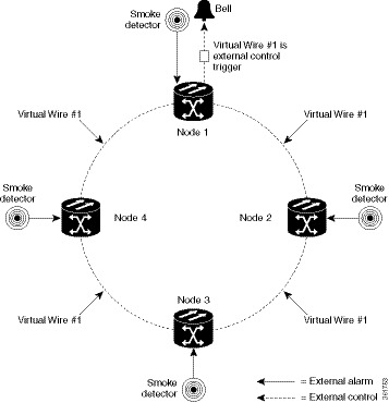
When using AIC virtual wires, you can:
-
Assign different external devices to the same virtual wire.
-
Assign virtual wires as the trigger type for different external controls.
Alarm Suppression
The following sections explain alarm suppression features for the ONS 15454 NCS.
Alarms Suppressed for Maintenance
When you place a port in OOS,MT administrative state, this raises the alarm suppressed for maintenance (AS-MT) alarm in the Conditions and History windows and causes subsequently raised alarms for that port to be suppressed.
Note |
AS-MT can be seen in the Alarms window as well if you have set the Filter dialog box to show NA severity events. |
While the facility is in the OOS,MT state, any alarms or conditions that are raised and suppressed on it (for example, a transmit failure [TRMT] alarm) are reported in the Conditions window and show their normal severity in the Sev column. The suppressed alarms are not shown in the Alarms and History windows. (These windows only show AS-MT). When you place the port back into IS,AINS administrative state, the AS-MT alarm is resolved in all three windows. Suppressed alarms remain raised in the Conditions window until they are cleared.
Alarms Suppressed by User Command
In the node view (single-shelf mode) or shelf view (multishelf mode) Provisioning > Alarm Profiles tabs > Alarm Behavior tabs, the ONS 15454 and NCS has an alarm suppression option that clears raised alarm messages for the node, chassis, one or more slots (cards), or one or more ports. Using this option raises the alarms suppressed by user command, or AS-CMD alarm. The AS-CMD alarm, like the AS-MT alarm, appears in the Conditions, and History windows. Suppressed conditions (including alarms) appear only in the Conditions window--showing their normal severity in the Sev column. When the Suppress Alarms check box is cleared, the AS-CMD alarm is cleared from all three windows.
Note |
AS-MT can be seen in the Alarms window as well if you have set the Filter dialog box to show NA severity events. |
A suppression command applied at a higher level does not supersede a command applied at a lower level. For example, applying a node-level alarm suppression command makes all raised alarms for the node appear to be cleared, but it does not cancel out card-level or port-level suppression. Each of these conditions can exist independently and must be cleared independently.
 Caution |
Use alarm suppression with caution. If multiple CTC or TL1 sessions are open, suppressing the alarms in one session suppresses the alarms in all other open sessions. |
Multishelf Configuration Alarming
Multishelf systems can share a single IP address among shelves and also correlate optical signal alarms. Ethernet alarm-raising for this configuration also differs from alarm-raising for single-shelf configurations. This section explains how alarms are viewed on a multishelf configuration, how alarm locations are determined, and how multishelf alarming differs from single-shelf alarming.
Viewing Multishelf Alarmed Entities
The multishelf view in CTC shows which slots are occupied in each shelf of the configuration as shown in the following figure.
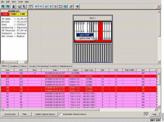
You can determine where an alarm is raised by viewing the Object column. The entry there (for example, FAC-1-3-1) tells you the entity (“fac,” or facility), shelf, slot, and port. In shelf view, the Alarms and Conditions tabs also contain a Shelf column that indicates where the alarmed card is located.
Multishelf-Specific Alarming
The following sections explain how Ethernet communication alarms and correlated multishelf alarms are processed in the ONS 15454 and NCS DWDM system.
Ethernet Communication Alarms
The Ethernet interface card (MS-ISC) that is required for multishelf configurations does not raise traditional Ethernet alarms, such as CARLOSS, that apply to transponder (TXP) or muxponder (MXP) client ports. Instead, MS-ISC card alarms are raised on the shelf as EQPT alarms. These alarms include Duplicate Shelf ID (DUP-SHELF-ID) and Shelf Communication Failure (SHELF-COMM-FAIL).
Multishelf Correlated Alarms
ITU-T G.798-based alarm correlation simplifies alarm reporting for DWDM channels. Communication failures including Loss of Signal (LOS), Loss of Signal Payload (LOS-P), and Optical Power Receive Fail-Loss of Light (OPWR-LFAIL) generate multiple conditions at each affected node and channel. Correlation simplifies troubleshooting because a single alarm is reported for each root cause. (The original alarms retain their severity in the Conditions window.)
The Payload Missing Indication (PMI) condition is raised at the far end to correlate optical multiplex section (OMS) and optical transmission section (OTS) communication failures. A single PMI condition is sent when every channel on the aggregated port is lost, that is, when there are no pass-through channels or active added channels in service. If there are added channels on the node, the Forward Defect Indication (FDI) condition is raised at the near end to indicate there are no pass-through optical channels (OCH) in service.
Threshold Crossing Alert Suppression
This section describes threshold crossing alert (TCA) suppression on TXP and MXP cards when they are installed in a DWDM node.
Overview
Threshold default settings define the default cumulative values (thresholds) beyond which a TCA will be raised. TCAs make it possible to monitor the network and detect errors early.
The following thresholds are monitored for TXP and MXP cards:
-
Optical Thresholds
-
ITU-T G.709 Thresholds
-
SONET and SDH Thresholds
-
FEC Thresholds
Threshold defaults are defined for near end and/or far end and at 15-minute or one-day intervals.
When LOS-P, LOS, or LOF alarms occur on the TXP./MXP cards, different TCAs are suppressed. Which TCAs are suppressed by an alarm depends on how the trunk is configured (ITU-T G.709, SONET, or SDH). The reason for suppressing the TCAs after the alarm occurs is to prevent a flood of TCAs after a system failure.
TCA suppression does not extend to optical thresholds such as OPR (optical power received). Optical threshold TCAs can effectively be suppressed by setting their thresholds to the maximum value.TCA suppression also does not extend to client ports; it only applies to TXP and MXP trunk ports when they are configured as ITU-T G.709, SONET, or SDH. TCA suppression does not extend to 10GE payloads.
Note |
Suppressed TCAs are not reported as Not Reported (NR) conditions. As a result, suppressed TCAs do not appear in the CTC Conditions tab and they cannot be retrieved with the RTRV-COND TL1 command. |
G.709, SONET, and SDH TCA Groups
This section lists the TCAs that are suppressed for each alarm. TCA suppression is determined by how framing is configured for TXP and MXP trunks.
The following table lists the TCAs for each type of trunk framing and alarm.
|
Alarm |
TXP/MXP Trunk Framing |
TCA Suppressed |
|
LOS-P and LOF |
G.709 |
BBE-SM ES-SM SES-SM UAS-SM FC-SM ESR-SM SESR-SM BBER-SM BBE-PM ES-PM SES-PM UAS-PM FC-PM ESR-PM SESR-PM BBER-PM BIT-EC UNC-WORDS |
|
LOS or LOF |
SONET |
ES-S SES-S SEFS-S CV-S ES-L SES-L UAS-L CV-L FC-L |
|
LOS or LOF |
SDH |
RS-ES RS-ESR RS-SES RS-SESR RS-BBR RS-BBER RS-UAS RS-EB MS-ES MS-ESR MS-SES MS-SESR MS-BBR MS-BBER MS-UAS MS-EB |
Procedures for Alarm Management
The following section lists procedures and tasks related to alarm management.
Before you Begin
This section lists the chapter procedures (NTPs) related to alarm management. Turn to a procedure for applicable tasks (DLPs).
-
NTP-G63 Document Existing Provisioning—Complete this procedure as needed to print or export node data.
-
NTP-G64 View Alarms, History, Events, and Conditions—Complete this procedure as needed to see alarms and conditions occurring on the node and a complete history of alarm and condition messages.
-
NTP-G65 Delete Cleared Alarms from Display—Complete this procedure as needed to delete cleared alarm information.
-
NTP-G66 View Alarm-Affected Circuits—Complete this procedure as needed to find circuits that are affected by a particular alarm or condition.
-
NTP-G67 View Alarm Counts on the LCD for a Node, Shelf, Slot, or Port—Complete this procedure as needed to see a statistical count of alarms that have occurred for a slot or port.
-
NTP-G68 Create, Download, and Assign Alarm Severity Profiles—Complete this procedure as needed to change the default severity for certain alarms, to assign the new severities to a port, card, or node, and to delete alarm profiles.
-
NTP-G69 Enable, Modify, or Disable Alarm Severity Filtering—Complete this procedure as needed to enable, disable, or modify alarm severity filtering in the Conditions, Alarms, or History screens at the node or network level.
-
NTP-G70 Suppress Alarms or Discontinue Alarm Suppression—Complete this procedure as needed to suppress reported alarms at the port, card, or node level and to disable the suppress command to resume normal alarm reporting.
-
NTP-G72 Provision External Alarms and Controls on the Alarm Interface Controller-International Card—Complete this procedure as needed to provision external alarms and controls on the Alarm Interface Controller–International (AIC-I) card.
-
NTP-G277 Provision Alarms and Controls on the TNC, TNCE, TNCS/TNCS-O, TSC, or TSCE Card—Complete this procedure as needed to provision external alarms and controls on the TNC, TNCE, TSC, or TSCE card.
NTP-G63 Document Existing Provisioning
|
Purpose |
Use this procedure to document existing provisioning by printing or exporting card, node, or network CTC information. You can export information as delineated text files to other applications. This procedure is useful for network record keeping and troubleshooting. |
|
Tools/Equipment |
A printer connected to the CTC computer by a direct or network connection |
|
Prerequisite Procedures |
|
|
Required/As Needed |
As needed |
|
Onsite/Remote |
Onsite or remote |
|
Security Level |
Retrieve or higher |
SUMMARY STEPS
- As needed, complete the DLP-G113 Print CTC Data task.
- As needed, complete the DLP-G114 Export CTC Data task.
DETAILED STEPS
|
Step 1 |
As needed, complete the DLP-G113 Print CTC Data task. |
|
Step 2 |
As needed, complete the DLP-G114 Export CTC Data task. Stop. You have completed this procedure. |
DLP-G113 Print CTC Data
|
Purpose |
This task prints CTC card, node, or network data in graphical or tabular format on a Windows-provisioned printer. |
|
Tools/Equipment |
Printer connected to the CTC computer by a direct or network connection |
|
Prerequisite Procedures |
"DLP-G46 Log into CTC" task in the "Connect the PC and Log into the GUI" document. |
|
Required/As Needed |
As needed |
|
Onsite/Remote |
Onsite or remote |
|
Security Level |
Retrieve or higher |
SUMMARY STEPS
- Click the tab (and subtab, if present) containing the information you want to print. For example, click the Alarms tab to print Alarms window data.
- From the File menu choose Print. The Print dialog box appears.
- In the Print dialog box, click a printing option:
- Entire Frame—Prints the entire CTC window including the graphical view of the card, node, or network. This option is available for all windows.
- Tabbed View—Prints the lower half of the CTC window containing tabs and data. The printout includes the selected tab (on top) and the data shown in the tab window. For example, if you print the History window Tabbed View, you print only history items appearing in the window. This option is available for all windows.
- Table Contents—Prints CTC data in table format without graphical representations of shelves, cards, or tabs. This option applies
to all windows except:
-
N ode view (single-shelf mode) or multishelf view (multishelf mode) Provisioning > General > General, Multishelf Config, and Power Monitor windows
-
Node view (single-shelf mode) or multishelf view (multishelf mode) Provisioning > Network > General window
-
Node view (single-shelf mode) or multishelf view (multishelf mode) Provisioning > Security > Policy, Access, Data Comm, and Legal Disclaimer windows
-
Node view (single-shelf mode) or multishelf view (multishelf mode) Provisioning > SNMP window
-
Node view (single-shelf mode) or shelf view (multishelf mode) Provisioning > Timing window > General and BITS Facilities windows
-
Node view (single-shelf mode) or multishelf view (multishelf mode) Provisioning > OSI > Main Setup window
-
Node view (single-shelf mode) or multishelf view (multishelf mode) Provisioning > OSI > TARP > Config window
-
Node view (single-shelf mode) or multishelf view (multishelf mode) Provisioning > Comm Channels > LMP > General window
-
Node view (single-shelf mode) or multishelf view (multishelf mode) Provisioning > WDM-ANS > Node Setup window
-
Node view (single-shelf mode) or shelf view (multishelf mode) Maintenance > Overhead XConnect window
-
Node view (single-shelf mode) or multishelf view (multishelf mode) Maintenance > Database window
-
Node view (single-shelf mode), multishelf view (multishelf mode), or shelf view (multishelf mode) Maintenance > Diagnostic window
-
Node view (single-shelf mode) or shelf view (multishelf mode) Maintenance > Protection window
-
Node view (single-shelf mode) or shelf view (multishelf mode) Maintenance > Timing > Source window
-
Node view (single-shelf mode) or shelf view (multishelf mode) Maintenance > DWDM > ROADM Power Monitoring window
-
- Click OK.
- In the Windows Print dialog box, click a printer and click OK.
- Repeat this task for each window that you want to print.
- Return to your originating procedure (NTP).
DETAILED STEPS
|
Step 1 |
Click the tab (and subtab, if present) containing the information you want to print. For example, click the Alarms tab to print Alarms window data. The print operation is available for all network, node, and card view windows. |
||
|
Step 2 |
From the File menu choose Print. The Print dialog box appears. |
||
|
Step 3 |
In the Print dialog box, click a printing option:
The Table Contents option prints all the data contained in a table and the table column headings. For example, if you print the History window Table Contents view, you print all data included in the table whether or not items appear in the window.
|
||
|
Step 4 |
Click OK. |
||
|
Step 5 |
In the Windows Print dialog box, click a printer and click OK. |
||
|
Step 6 |
Repeat this task for each window that you want to print. |
||
|
Step 7 |
Return to your originating procedure (NTP). |
DLP-G114 Export CTC Data
|
Purpose |
This task exports CTC table data as delineated text to view or edit the data in text editor, word processing, spreadsheet, database management, or web browser applications. |
|
Tools/Equipment |
None |
|
Prerequisite Procedures |
"DLP-G46 Log into CTC" task in the "Connect the PC and Log into the GUI" document. |
|
Required/As Needed |
As needed |
|
Onsite/Remote |
Onsite or remote |
|
Security Level |
Retrieve or higher |
SUMMARY STEPS
- Click the tab containing the information you want to export (for example, the Alarms tab or the Circuits tab).
- If you want to export detailed circuit information, complete the following:
- Choose Export from the File menu. The Export dialog box appears.
- In the Export dialog box, click a data format:
- As HTML—Saves data as a simple HTML table file without graphics. The file must be viewed or edited with applications such as Microsoft Internet Explorer or other applications capable of opening HTML files.
- As CSV—Saves the CTC table as comma-separated values (CSV). This option does not apply to the Node view (single-shelf mode) or shelf view (multishelf mode) Maintenance > Timing > Report window.
- As TSV—Saves the CTC table as tab-separated values (TSV).
- If you want to open a file in a text editor or word processor application, procedures will vary. Typically, you can use the File > Open command to view the CTC data, or you can double-click the file name and choose an application such as Notepad.
- If you want to open the file in spreadsheet and database management applications, procedures will vary. Typically, you need to open the application and choose File > Import, then choose a delimited file to format the data in cells.
- Node view (single-shelf mode) or multishelf view (multishelf mode) Provisioning > General > General, Multishelf Config, and Power Monitor windows
- Node view (single-shelf mode) or multishelf view (multishelf mode) Provisioning > Network > General window
- Node view (single-shelf mode) or multishelf view (multishelf mode) Provisioning > Security > Policy, Access, Data Comm, and Legal Disclaimer windows
- Provisioning > SNMP window
- Node view (single-shelf mode) or shelf view (multishelf mode) Provisioning > Timing > General and BITS Facilities windows
- Node view (single-shelf mode) or multishelf view (multishelf mode) Provisioning > OSI > Main Setup window
- Node view (single-shelf mode) or multishelf view (multishelf mode) Provisioning > OSI > TARP > Config window
- Node view (single-shelf mode) or multishelf view (multishelf mode) Provisioning > WDM-ANS > Node Setup window
- Node view (single-shelf mode) or multishelf view (multishelf mode) Provisioning > Comm Channels > LMP > General window
- Node view (single-shelf mode) or shelf view (multishelf mode) Maintenance > Overhead XConnect window
- Node view (single-shelf mode) or multishelf view (multishelf mode) Maintenance > Database window
- Node view (single-shelf mode), multishelf view (multishelf mode), or shelf view (multishelf mode) Maintenance > Diagnostic window
- Node view (single-shelf mode) or shelf view (multishelf mode) Maintenance > Protection window
- Node view (single-shelf mode) or shelf view (multishelf mode) Maintenance > Timing > Source windows
- Node view (single-shelf mode) or multishelf view (multishelf mode) Maintenance > DWDM > ROADM Power Monitoring window [ETSI only]
- Click OK.
- In the Save dialog box, enter a name in the File name field using one of the following formats:
- filename.html for HTML files
- filename.csv for CSV files
- filename.tsv for TSV files
- Navigate to a directory where you want to store the file.
- Click Save.
- Repeat the task for each window that you want to export.
- Return to your originating procedure (NTP).
DETAILED STEPS
|
Step 1 |
Click the tab containing the information you want to export (for example, the Alarms tab or the Circuits tab). |
||
|
Step 2 |
If you want to export detailed circuit information, complete the following:
|
||
|
Step 3 |
Choose Export from the File menu. The Export dialog box appears. |
||
|
Step 4 |
In the Export dialog box, click a data format:
|
||
|
Step 5 |
If you want to open a file in a text editor or word processor application, procedures will vary. Typically, you can use the File > Open command to view the CTC data, or you can double-click the file name and choose an application such as Notepad. Text editor and word processor applications format the data exactly as it is exported, including comma or tab separators. All applications that open the data files allow you to format the data. |
||
|
Step 6 |
If you want to open the file in spreadsheet and database management applications, procedures will vary. Typically, you need to open the application and choose File > Import, then choose a delimited file to format the data in cells. Spreadsheet and database management programs also allow you to manage the exported data.
The export operation applies to all tabular data except:
|
||
|
Step 7 |
Click OK. |
||
|
Step 8 |
In the Save dialog box, enter a name in the File name field using one of the following formats:
|
||
|
Step 9 |
Navigate to a directory where you want to store the file. |
||
|
Step 10 |
Click Save. |
||
|
Step 11 |
Repeat the task for each window that you want to export. |
||
|
Step 12 |
Return to your originating procedure (NTP). |
NTP-G64 View Alarms, History, Events, and Conditions
|
Purpose |
Use this procedure to view current or historical alarms and conditions for a card, node, or network. This information is useful for monitoring and troubleshooting hardware and software events. |
|
Tools/Equipment |
None |
|
Prerequisite Procedures |
"DLP-G46 Log into CTC" task in the "Connect the PC and Log into the GUI" document. |
|
Required/As Needed |
As needed |
|
Onsite/Remote |
Onsite or remote |
|
Security Level |
Provisioning or higher |
SUMMARY STEPS
- Complete the DLP-G115 View Alarms as needed.
- Complete the DLP-G116 View Alarm or Event History as needed.
- Complete the DLP-G117 Change the Maximum Number of Session Entries for Alarm History as needed.
- Complete the DLP-G118 Display Alarms and Conditions Using Time Zone as needed.
- Complete the DLP-G119 Synchronize Alarms as needed.
- Complete the DLP-G120 View Conditions as needed.
DETAILED STEPS
|
Step 1 |
Complete the DLP-G115 View Alarms as needed. |
|
Step 2 |
Complete the DLP-G116 View Alarm or Event History as needed. |
|
Step 3 |
Complete the DLP-G117 Change the Maximum Number of Session Entries for Alarm History as needed. |
|
Step 4 |
Complete the DLP-G118 Display Alarms and Conditions Using Time Zone as needed. |
|
Step 5 |
Complete the DLP-G119 Synchronize Alarms as needed. |
|
Step 6 |
Complete the DLP-G120 View Conditions as needed. Stop. You have completed this procedure. |
DLP-G115 View Alarms
|
Purpose |
Use this task to view current alarms on a card, node, or network. |
|
Tools/Equipment |
None |
|
Prerequisite Procedures |
"DLP-G46 Log into CTC" task in the "Connect the PC and Log into the GUI" document. |
|
Required/As Needed |
As needed |
|
Onsite/Remote |
Onsite or remote |
|
Security Level |
Provisioning or higher |
SUMMARY STEPS
- In card, node (single-shelf mode) or shelf view (multishelf mode), or network view, click the Alarms tab to view the alarms for that card, node, shelf, or network.
- If alarms are present, refer to the Cisco ONS 15454 DWDM Troubleshooting Guide and Cisco NCS 2000 Series Troubleshooting Guide for information and troubleshooting procedures.
- Return to your originating procedure (NTP).
DETAILED STEPS
|
Step 1 |
In card, node (single-shelf mode) or shelf view (multishelf mode), or network view, click the Alarms tab to view the alarms for that card, node, shelf, or network. The following table describes the columns in the Alarms window.
The following table lists the color codes for node alarm and condition severities.
|
||||||||||||||||||||||||||||||||||||||||||||||||||||||
|
Step 2 |
If alarms are present, refer to the Cisco ONS 15454 DWDM Troubleshooting Guide and Cisco NCS 2000 Series Troubleshooting Guide for information and troubleshooting procedures. |
||||||||||||||||||||||||||||||||||||||||||||||||||||||
|
Step 3 |
Return to your originating procedure (NTP). |
DLP-G116 View Alarm or Event History
|
Purpose |
This task is used to view past cleared and uncleared ONS 15454 and NCS alarm messages at the card, node, or network level. This task is useful for troubleshooting configuration, traffic, or connectivity issues that are indicated by alarms. |
|
Tools/Equipment |
None |
|
Prerequisite Procedures |
"DLP-G46 Log into CTC" task in the "Connect the PC and Log into the GUI" document. |
|
Required/As Needed |
As needed |
|
Onsite/Remote |
Onsite or remote |
|
Security Level |
Retrieve or higher |
Procedure
|
Step 1 |
Decide whether you want to view the alarm message history at the Network, node (single-shelf mode), multishelf (multishelf mode), shelf (multishelf mode), or card level. |
|
Step 2 |
To view alarm history for a single-shelf node: |
|
Step 3 |
To view alarm history for a multishelf node: |
|
Step 4 |
To view alarm history for a shelf within a multishelf: |
|
Step 5 |
To view network alarm history: |
|
Step 6 |
To view card alarm history: |
|
Step 7 |
Return to your originating procedure (NTP). |
DLP-G117 Change the Maximum Number of Session Entries for Alarm History
|
Purpose |
This task changes the maximum number of session entries included in the alarm history. Use this task to expand the history list to save information for future reference or troubleshooting. This task changes the maximum history entries recorded for CTC sessions. It does not affect the maximum number of history entries viewable for a network, node, or card. |
|
Tools/Equipment |
None |
|
Prerequisite Procedures |
"DLP-G46 Log into CTC" task in the "Connect the PC and Log into the GUI" document. |
|
Required/As Needed |
As needed |
|
Onsite/Remote |
Onsite or remote |
|
Security Level |
Provisioning or higher |
SUMMARY STEPS
- From the CTC Edit menu, choose Preferences.
- Click the up or down arrow buttons next to the Maximum History Entries field to change the entry.
- Click Apply and OK.
- Return to your originating procedure (NTP).
DETAILED STEPS
|
Step 1 |
From the CTC Edit menu, choose Preferences. The CTC Preferences dialog box appears as shown below 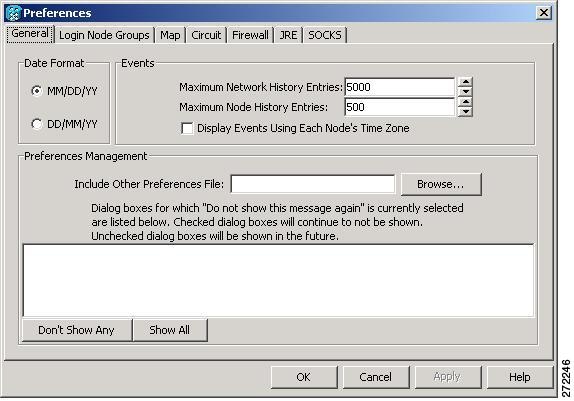 |
||
|
Step 2 |
Click the up or down arrow buttons next to the Maximum History Entries field to change the entry. |
||
|
Step 3 |
Click Apply and OK.
|
||
|
Step 4 |
Return to your originating procedure (NTP). |
DLP-G118 Display Alarms and Conditions Using Time Zone
|
Purpose |
This task changes the time stamp for events to the time zone of the ONS node reporting the alarm. By default, the events time stamp is set to the time zone for the CTC workstation. |
|
Tools/Equipment |
None |
|
Prerequisite Procedures |
"DLP-G46 Log into CTC" task in the "Connect the PC and Log into the GUI" document. |
|
Required/As Needed |
As needed |
|
Onsite/Remote |
Onsite or remote |
|
Security Level |
Provisioning or higher |
SUMMARY STEPS
- From the CTC Edit menu, choose Preferences.
- Check the Display Events Using Each Node’s Time Zone check box. The Apply button is enabled.
- Click Apply and OK.
- Return to your originating procedure (NTP).
DETAILED STEPS
|
Step 1 |
From the CTC Edit menu, choose Preferences. The CTC Preferences dialog box appears, see figure CTC Preferences Dialog Box |
|
Step 2 |
Check the Display Events Using Each Node’s Time Zone check box. The Apply button is enabled. |
|
Step 3 |
Click Apply and OK. |
|
Step 4 |
Return to your originating procedure (NTP). |
DLP-G119 Synchronize Alarms
|
Purpose |
This task is used to view ONS 15454 and NCS events at the card, node, or network level and to refresh the alarm listing so that you can check for new and cleared alarms and conditions. |
|
Tools/Equipment |
None |
|
Prerequisite Procedures |
"DLP-G46 Log into CTC" task in the "Connect the PC and Log into the GUI" document. |
|
Required/As Needed |
As needed |
|
Onsite/Remote |
Onsite or remote |
|
Security Level |
Retrieve or higher |
Procedure
|
Step 1 |
At card, node, or network view, click the Alarms tab. |
||
|
Step 2 |
Click Synchronize. This button causes CTC to retrieve a current alarm summary for the card, node, or network. This step is optional because CTC updates the Alarms window automatically as raise/clear messages arrive from the node.
|
||
|
Step 3 |
Return to your originating procedure (NTP). |
DLP-G120 View Conditions
|
Purpose |
This task is used to view conditions (events with a Not Reported [NR] severity) at the card, node, or network level. Conditions give you a clear record of changes or events that do not result in alarms. |
|
Tools/Equipment |
None |
|
Prerequisite Procedures |
"DLP-G46 Log into CTC" task in the "Connect the PC and Log into the GUI" document. |
|
Required/As Needed |
As needed |
|
Onsite/Remote |
Onsite or remote |
|
Security Level |
Retrieve or higher |
Conditions include all fault conditions raised on the node, whether or not they are reported.
Note |
Alarms and conditions can be unreported if they are filtered out of the display. See the DLP-G126 Enable Alarm Filtering for information on filtering. |
Events that are reported as Major (MJ), Minor (MN), or Critical (CR) severities are alarms. Events that are reported as Not Alarmed (NA) are conditions. Conditions that are not reported at all are marked Not Reported (NR) in the Conditions window severity column.
Conditions that have a default severity of Critical (CR), Major (MJ), Minor (MN), or Not Alarmed (NA) but are not reported due to exclusion or suppression are shown as NR in the Conditions window.
Note |
Current conditions are shown with the severity chosen in the alarm profile, if used. For more information about alarm profiles, see the NTP-G68 Create, Download, and Assign Alarm Severity Profiles.
Note |
When a port is placed in the Out-of-Service and Management, Maintenance (OOS-MA,MT) (ANSI) or Locked-enabled, maintenance (ETSI) service state, it raises an Alarms Suppressed for Maintenance (AS-MT) condition. For information about alarm and condition troubleshooting, refer to the Cisco ONS 15454 DWDM Troubleshooting Guide and Cisco NCS 2000 Series Troubleshooting Guide. |
Procedure
|
Step 1 |
From card, node, or network view, click the Conditions tab. |
|
Step 2 |
Check Retrieve. The Retrieve button requests the current set of fault conditions from the node, card, or network. The window is not updated when events change on the node. You must click Retrieve to see any changes. |
|
Step 3 |
If you want to apply exclusion rules, check the Exclude Same Root Cause check box at the node or network view, but do not check the Exclude Same Root Cause check box in card view. An exclusion rule eliminates all lower-level alarms or conditions that originate from the same cause. For example, a fiber break might cause a loss of signal (LOS) alarm, an alarm indication signal (AIS) condition, and a signal fail (SF) condition. If you check the Exclude Same Root Cause check box, only the LOS alarm will appear. According to Telcordia, exclusion rules apply to a query of “all conditions from a node.” |
|
Step 4 |
Return to your originating procedure (NTP). |
NTP-G65 Delete Cleared Alarms from Display
|
Purpose |
Use this procedure to delete Cleared (C) status alarms from the Alarms window or transient messages from the CTC History window. |
|
Tools/Equipment |
None |
|
Prerequisite Procedures |
"DLP-G46 Log into CTC" task in the "Connect the PC and Log into the GUI" document. |
|
Required/As Needed |
As needed |
|
Onsite/Remote |
Onsite or remote |
|
Security Level |
Retrieve or higher |
Procedure
|
Step 1 |
To delete cleared node-level or multishelf-level alarms: |
|
Step 2 |
To delete cleared card-level alarms: |
|
Step 3 |
To delete cleared network-level alarms: |
|
Step 4 |
To remove the transient messages from the History window, click Delete Cleared Alarms. Transient messages are single messages, not raise-and-clear pairs (that is, they do not have companion messages stating that they are cleared). Stop. You have completed this procedure. |
NTP-G66 View Alarm-Affected Circuits
|
Purpose |
Use this procedure to view all optical channel network connections (OCHNCs) optical channel client connections (OCHCC), optical channel trail, and ONS 15454 and NCS circuits, if any, that are affected by an alarm. |
|
Tools/Equipment |
None |
|
Prerequisite Procedures |
|
|
Required/As Needed |
As needed |
|
Onsite/Remote |
Onsite or remote |
|
Security Level |
Retrieve or higher |
Procedure
|
Step 1 |
In network, node, shelf, or card view, click the Alarms tab and then right-click anywhere in the row of an active alarm. |
|
Step 2 |
From the right-click menu, select the Select Affected Circuits option. The Circuits window appears with the affected OCHNC, OCHCC, or OCH trail circuit highlighted. Stop. You have completed this procedure. |
NTP-G348 Viewing Demoted Alarm List
|
Purpose |
Use this procedure to view all the alarms, if any that were demoted by the alarm. |
|
Tools/Equipment |
None |
|
Prerequisite Procedures |
|
|
Required/As Needed |
As needed |
|
Onsite/Remote |
Onsite or remote |
|
Security Level |
Retrieve or higher |
Procedure
|
Step 1 |
In network, node, shelf, or card view, click the Alarms tab and then right-click anywhere in the row of an active alarm or condition. |
|
Step 2 |
From the right-click menu, select the Show Demoted Alarms option. The alarms that were demoted by the root cause alarm are displayed. Stop. You have completed this procedure. |
NTP-G67 View Alarm Counts on the LCD for a Node, Shelf, Slot, or Port
|
Purpose |
Use this procedure to view an alarm summary for a node, shelf, slot, or port without using CTC. |
|
Tools/Equipment |
None |
|
Prerequisite Procedures |
“Install the Cisco NCS 2002 and Cisco NCS 2006 , Cisco ONS 15454, ONS 15454 M2, and ONS 15454 M6 Shelf” chapters in the Cisco ONS 15454 Hardware Installation GuideCisco NCS 2002 and Cisco NCS 2006 Hardware Installation Guide. |
|
Required/As Needed |
As needed |
|
Onsite/Remote |
Onsite |
|
Security Level |
None |
Note |
In the ONS 15454 M2 and NCS 2002 shelf assembly, the LCD panel and the Slot, Port, and Status buttons are present on the fan-tray assembly. In the ONS 15454 M6 and NCS 2006 shelf assembly, the LCD is a separate unit installed above the external connection unit (ECU) and ECU2; the Slot, Port, and Status buttons are present on the LCD unit. |
Procedure
|
Step 1 |
If you want to view the entire alarm summary:
|
||
|
Step 2 |
Press the Status button to see a summary of alarms and severities for the node. You will see a message similar to “Alm Ct: 2: MJ:2 MN:2,” meaning that there are two critical alarms, two major alarms, and two minor alarms. |
||
|
Step 3 |
If you want to see alarm counts for a particular shelf (node controller or subtending shelf) in a multishelf configuration, press the Slot button on that shelf until “Shelf” appears on the LCD. Then press the Port button until you see the direction, “Status=Alm Ct.” |
||
|
Step 4 |
Press the Status button to see a summary of alarms and severities for that particular shelf. |
||
|
Step 5 |
If you want to see alarm counts for a particular slot, such as the alarms for an OC-3 card in Slot 3, press the Slot button until you see “Slot-3” on the LCD. You will see the direction, “Status=Alm Ct Sum.” |
||
|
Step 6 |
Press the Status button to see a summary of alarms and severities against the slot. For example, you might see “Slot-3 Alm Sum:0 MJ:1 MN:2.” This means that there are no critical alarms, one major alarm, and two minor alarms against the slot. |
||
|
Step 7 |
If you want to view the alarms against a port on the card, such as Port 3 of the OC-3 card you viewed previously, press the Port button until you see “Port-3 Status=Alm Ct.” |
||
|
Step 8 |
Press Status to view alarm counts against the port. You will see a message similar to “Slot-3 Port-0 Ct:0 MJ:1 MN:0.” This means that there is one major alarm against this port. The shelf LCD panel on the shelf assembly is shown in Shelf LCD Panel . To return to the previous view from the Port screen, continue to press Port until the display cycles through all the ports on the slot. To return to the node menu from the Slot screen, press Slot until you cycle through all the slots and see “Node.” If you do not press any buttons, the LCD will return to its default display with the node name. However, if you did not cycle through the options to return to the node status, you will see the slot or port where you last checked status.
Stop. You have completed this procedure. |
NTP-G68 Create, Download, and Assign Alarm Severity Profiles
|
Purpose |
This procedure creates a customized alarm profile at the network, node, or card level. This procedure also provides links to tasks that describe how to assign custom severities individually to each port, card, or node, and to delete alarm profiles. |
|
Tools/Equipment |
None |
|
Prerequisite Procedures |
|
|
Required/As Needed |
As needed |
|
Onsite/Remote |
Onsite or remote |
|
Security Level |
Provisioning or higher |
SUMMARY STEPS
- To create, clone, or modify an alarm profile continue with the next step, or go to Step 3 to download an alarm profile.
- Complete the DLP-G121 Create a New or Cloned Alarm Severity Profile Using CTC. This task clones a current alarm profile, renames the profile, and customizes the new profile.
- Complete the DLP-G122 Download an Alarm Severity Profile Using CTC. This task downloads an alarm severity profile from a CD or a node.
- As necessary, complete the DLP-G123 Apply Alarm Profiles to Ports or the DLP-G124 Apply Alarm Profiles to Cards and Nodes.
- As necessary, complete the DLP-G125 Delete Alarm Severity Profiles Using CTC.
DETAILED STEPS
|
Step 1 |
To create, clone, or modify an alarm profile continue with the next step, or go to Step 3 to download an alarm profile. |
||
|
Step 2 |
Complete the DLP-G121 Create a New or Cloned Alarm Severity Profile Using CTC. This task clones a current alarm profile, renames the profile, and customizes the new profile. |
||
|
Step 3 |
Complete the DLP-G122 Download an Alarm Severity Profile Using CTC. This task downloads an alarm severity profile from a CD or a node.
|
||
|
Step 4 |
As necessary, complete the DLP-G123 Apply Alarm Profiles to Ports or the DLP-G124 Apply Alarm Profiles to Cards and Nodes. |
||
|
Step 5 |
As necessary, complete the DLP-G125 Delete Alarm Severity Profiles Using CTC. |
DLP-G121 Create a New or Cloned Alarm Severity Profile Using CTC
|
Purpose |
This task creates a custom severity profile or clones and modifies the default severity profile. |
|
Tools/Equipment |
None |
|
Prerequisite Procedures |
|
|
Required/As Needed |
As needed |
|
Onsite/Remote |
Onsite or remote |
|
Security Level |
Provisioning or higher |
SUMMARY STEPS
- From the CTC window View menu, select Go To Network View.
- To access the alarm profile editor from network view, click the Provisioning > Alarm Profile tab.
- If you want to create a new profile, click New. Continue with Step 9.
- If you want to create a profile using an existing profile located on the node, click Load and From Node in the Load Profiles dialog box.
- If you want to create a profile using an existing profile located in a file that is stored locally or on a network drive, click From File in the Load Profiles dialog box.
- Click OK.
- Right-click anywhere in the profile column to view the profile editing shortcut menu.
- Click Clone in the shortcut menu.
- In the New Profile dialog box, enter a name in the New Profile Name field.
- Click OK.
- Modify (customize) the new alarm profile:
- All Critical (CR) or Major (MJ) default or user-defined severity settings are demoted to Minor (MN) in Non-Service-Affecting (NSA) situations as defined in Telcordia GR-474-CORE.
- Default severities are used for all alarms and conditions until you create and apply a new profile.
- Changing a severity to inherited (I) or unset (U) does not change the severity of the alarm.
- After you have customized the new alarm profile, right-click the profile column to highlight it.
- Click Store.
- In the Store Profiles dialog box, click To Node(s) and go to Step 14.a, or click To File and go to Step 14.b.
- As needed, perform any of the following actions. The following options are located at the bottom of the Provisioning > Alarm Profile window.
- Click the Hide Identical Rows check box to configure the Alarm Profiles window to view rows with dissimilar severities.
- Click the Only show service-affecting severities check box to configure the Alarm Profiles window not to display Minor and some Major alarms that will not affect service.
- Return to your originating procedure (NTP).
DETAILED STEPS
|
Step 1 |
From the CTC window View menu, select Go To Network View. |
||
|
Step 2 |
To access the alarm profile editor from network view, click the Provisioning > Alarm Profile tab.
|
||
|
Step 3 |
If you want to create a new profile, click New. Continue with Step 9. |
||
|
Step 4 |
If you want to create a profile using an existing profile located on the node, click Load and From Node in the Load Profiles dialog box.
|
||
|
Step 5 |
If you want to create a profile using an existing profile located in a file that is stored locally or on a network drive, click From File in the Load Profiles dialog box. |
||
|
Step 6 |
Click OK. The alarm severity profile appears in the Alarm Profiles window. The alarm profile list contains a primary list of alarms that is used for a mixed node network. |
||
|
Step 7 |
Right-click anywhere in the profile column to view the profile editing shortcut menu. |
||
|
Step 8 |
Click Clone in the shortcut menu.
|
||
|
Step 9 |
In the New Profile dialog box, enter a name in the New Profile Name field. Profile names must be unique. If you try to import or name a profile that has the same name as another profile, CTC adds a suffix to create a new name. |
||
|
Step 10 |
Click OK. A new alarm profile (named in Step 9) is created.
(If you are creating profiles, you can apply these separately at any level. To do this, refer to the DLP-G124 Apply Alarm Profiles to Cards and Nodes.) |
||
|
Step 11 |
Modify (customize) the new alarm profile:
|
||
|
Step 12 |
After you have customized the new alarm profile, right-click the profile column to highlight it. |
||
|
Step 13 |
Click Store. |
||
|
Step 14 |
In the Store Profiles dialog box, click To Node(s) and go to Step 14.a, or click To File and go to Step 14.b. |
||
|
Step 15 |
As needed, perform any of the following actions. The following options are located at the bottom of the Provisioning > Alarm Profile window.
|
||
|
Step 16 |
Return to your originating procedure (NTP). |
DLP-G122 Download an Alarm Severity Profile Using CTC
|
Purpose |
This task downloads a custom alarm severity profile from a network-drive-accessible CD-ROM or hard disk location. |
|
Tools/Equipment |
None |
|
Prerequisite Procedures |
|
|
Required/As Needed |
As needed |
|
Onsite/Remote |
Onsite or remote |
|
Security Level |
Provisioning or higher |
Note |
You must always store the alarm profile after editing it. If you edit an alarm profile without saving it, changes to the profile will be lost if you change views in CTC. |
SUMMARY STEPS
- To access the alarm profile editor from network view, click the Provisioning > Alarm Profiles tabs.
- Click Load.
- If you want to download a profile that exists on the node, click From Node in the Load Profiles dialog box.
- If you want to download a profile that is stored locally or on a network drive, click From File in the Load Profile dialog box.
- Click OK.
- Right-click anywhere in the downloaded profile column to view the profile editing shortcut menu.
- Click Store.
- In the Store Profiles dialog box, click To Node(s).
- Return to your originating procedure (NTP).
DETAILED STEPS
|
Step 1 |
To access the alarm profile editor from network view, click the Provisioning > Alarm Profiles tabs.
|
||
|
Step 2 |
Click Load. |
||
|
Step 3 |
If you want to download a profile that exists on the node, click From Node in the Load Profiles dialog box.
|
||
|
Step 4 |
If you want to download a profile that is stored locally or on a network drive, click From File in the Load Profile dialog box. |
||
|
Step 5 |
Click OK. The downloaded profile appears at the right side of the Alarm Profiles window. |
||
|
Step 6 |
Right-click anywhere in the downloaded profile column to view the profile editing shortcut menu. |
||
|
Step 7 |
Click Store. |
||
|
Step 8 |
In the Store Profiles dialog box, click To Node(s). |
||
|
Step 9 |
Return to your originating procedure (NTP). |
DLP-G123 Apply Alarm Profiles to Ports
|
Purpose |
This task applies a custom or default alarm severity profile to a port or ports. |
|
Tools/Equipment |
None |
|
Prerequisite Procedures |
|
|
Required/As Needed |
As needed |
|
Onsite/Remote |
Onsite or remote |
|
Security Level |
Provisioning or higher |
Note |
You can also apply alarm profiles to cards using the DLP-G124 Apply Alarm Profiles to Cards and Nodes. |
SUMMARY STEPS
- In node view (single-shelf mode) or shelf view (multishelf mode), double-click the card that you want to change to open the card view.
- Click the Provisioning > Alarm Profiles > Alarm Behavior tabs.
- To apply profiles on a port basis:
- To apply profiles to all ports on a card:
- To reapply a previous alarm profile after you have applied a new one, select the previous profile and click Apply again.
- Return to your originating procedure (NTP).
DETAILED STEPS
|
Step 1 |
In node view (single-shelf mode) or shelf view (multishelf mode), double-click the card that you want to change to open the card view.
|
||
|
Step 2 |
Click the Provisioning > Alarm Profiles > Alarm Behavior tabs. Go to next step to apply profiles to a port. Go to DLP-G123 Apply Alarm Profiles to Ports to apply profiles to all ports on a card. |
||
|
Step 3 |
To apply profiles on a port basis:
|
||
|
Step 4 |
To apply profiles to all ports on a card: |
||
|
Step 5 |
To reapply a previous alarm profile after you have applied a new one, select the previous profile and click Apply again. |
||
|
Step 6 |
Return to your originating procedure (NTP). |
DLP-G124 Apply Alarm Profiles to Cards and Nodes
|
Purpose |
This task applies a custom or default alarm profile to cards or nodes. |
|
Tools/Equipment |
None |
|
Prerequisite Procedures |
|
|
Required/As Needed |
As needed |
|
Onsite/Remote |
Onsite or remote |
|
Security Level |
Provisioning or higher |
Note |
Alarm severity does not change for AR_MXP, AR_XP, and AR_XPE cards under the following conditions:
|
SUMMARY STEPS
- In node view (single-shelf mode) or shelf view (multishelf mode), click the Provisioning > Alarm Profiles > Alarm Behavior tab.
- To apply profiles to a card:
- To apply the profile to an entire node:
- Click Apply again.
- Return to your originating procedure (NTP).
DETAILED STEPS
|
Step 1 |
In node view (single-shelf mode) or shelf view (multishelf mode), click the Provisioning > Alarm Profiles > Alarm Behavior tab. |
|
Step 2 |
To apply profiles to a card:
|
|
Step 3 |
To apply the profile to an entire node:
|
|
Step 4 |
Click Apply again. |
|
Step 5 |
Return to your originating procedure (NTP). |
DLP-G125 Delete Alarm Severity Profiles Using CTC
|
Purpose |
This task deletes a custom or default alarm severity profile. |
|
Tools/Equipment |
None |
|
Prerequisite Procedures |
|
|
Required/As Needed |
As needed |
|
Onsite/Remote |
Onsite or remote |
|
Security Level |
Provisioning or higher |
SUMMARY STEPS
- To access the alarm profile editor from network view, click the Provisioning > Alarm Profiles tabs.
- Click the Alarm Type : Condition column.
- Click Delete.
- Click the node name in the Node Names list to highlight the profile location.
- Click the profile names that you want to delete in the Profile Names list.
- Click OK.
- Click Yes in the Delete Alarm Profile dialog box.
- Return to your originating procedure (NTP).
DETAILED STEPS
|
Step 1 |
To access the alarm profile editor from network view, click the Provisioning > Alarm Profiles tabs.
|
||||
|
Step 2 |
Click the Alarm Type : Condition column. |
||||
|
Step 3 |
Click Delete. The Select Node/Profile Combination for Delete dialog box appears.
|
||||
|
Step 4 |
Click the node name in the Node Names list to highlight the profile location.
|
||||
|
Step 5 |
Click the profile names that you want to delete in the Profile Names list. |
||||
|
Step 6 |
Click OK. |
||||
|
Step 7 |
Click Yes in the Delete Alarm Profile dialog box. |
||||
|
Step 8 |
Return to your originating procedure (NTP). |
NTP-G69 Enable, Modify, or Disable Alarm Severity Filtering
|
Purpose |
Use this procedure to start, change, or stop alarm filtering for one or more severities in the Alarms, Conditions, and History windows in all network nodes. |
|
Tools/Equipment |
None |
|
Prerequisite Procedures |
"DLP-G46 Log into CTC" task in the "Connect the PC and Log into the GUI" document. |
|
Required/As Needed |
As needed |
|
Onsite/Remote |
Onsite or remote |
|
Security Level |
Retrieve or higher |
SUMMARY STEPS
- As needed, complete the DLP-G126 Enable Alarm Filtering. This task enables alarm filtering at the card, shelf, node, and network views for all nodes in the network. Alarm filtering can be enabled for alarms, conditions, or events.
- As needed, complete the DLP-G127 Modify Alarm, Condition, and History Filtering Parameters to modify the alarm filtering for network nodes to show or hide particular alarms or conditions.
- As needed, complete the DLP-G128 Disable Alarm Filtering to disable alarm profile filtering for all network nodes.
DETAILED STEPS
|
Step 1 |
As needed, complete the DLP-G126 Enable Alarm Filtering. This task enables alarm filtering at the card, shelf, node, and network views for all nodes in the network. Alarm filtering can be enabled for alarms, conditions, or events. |
|
Step 2 |
As needed, complete the DLP-G127 Modify Alarm, Condition, and History Filtering Parameters to modify the alarm filtering for network nodes to show or hide particular alarms or conditions. |
|
Step 3 |
As needed, complete the DLP-G128 Disable Alarm Filtering to disable alarm profile filtering for all network nodes. Stop. You have completed this procedure. |
DLP-G126 Enable Alarm Filtering
|
Purpose |
This task enables alarm filtering for alarms, conditions, or event history in all network nodes. |
|
Tools/Equipment |
None |
|
Prerequisite Procedures |
"DLP-G46 Log into CTC" task in the "Connect the PC and Log into the GUI" document. |
|
Required/As Needed |
As needed |
|
Onsite/Remote |
Onsite or remote |
|
Security Level |
Retrieve or higher |
SUMMARY STEPS
- At the shelf, node, network, or card view, click the Alarms tab.
- Click the Filter tool icon on the right side of the bottom toolbar.
- If you want alarm filtering enabled when you view conditions, click on the Conditions tab and repeat Step 1 and Step 2.
- If you want alarm filtering enabled when you view alarm history, click on the Conditions tab and repeat Step 1 and Step 2.
- Return to your originating procedure (NTP).
DETAILED STEPS
|
Step 1 |
At the shelf, node, network, or card view, click the Alarms tab. |
||
|
Step 2 |
Click the Filter tool icon on the right side of the bottom toolbar.
Alarm filtering is enabled in the card, node, and network views of the same window for all nodes in the network. For example, if the Filter tool is enabled in the node view Alarms window, the network view Alarms window and card view Alarms window also show the tool enabled. |
||
|
Step 3 |
If you want alarm filtering enabled when you view conditions, click on the Conditions tab and repeat Step 1 and Step 2. |
||
|
Step 4 |
If you want alarm filtering enabled when you view alarm history, click on the Conditions tab and repeat Step 1 and Step 2. |
||
|
Step 5 |
Return to your originating procedure (NTP). |
DLP-G127 Modify Alarm, Condition, and History Filtering Parameters
|
Purpose |
This task changes alarm and condition reporting in all network nodes. |
|
Tools/Equipment |
None |
|
Prerequisite Procedures |
|
|
Required/As Needed |
As needed |
|
Onsite/Remote |
Onsite or remote |
|
Security Level |
Retrieve or higher |
SUMMARY STEPS
- At the shelf, node, network, or card view, click the Alarms tab, Conditions tab, or History tab.
- Click the Filter button on the left side of the bottom toolbar.
- In the Show Severity area, click the check boxes for the severities [Critical (CR), Major (MJ), Minor (MN), or Not Alarmed (NA)] that you want to be reported at the network level. Leave severity check boxes deselected (cleared) to prevent those severities from appearing.
- In the Time area, click the Show alarms between time limits check box to enable it. Click the up and down arrows in the From Date, To Date, and Time fields to modify the period of alarms that is shown.
- Click the Filter > Conditions tabs.
- Click Apply and OK.
- Return to your originating procedure (NTP).
DETAILED STEPS
|
Step 1 |
At the shelf, node, network, or card view, click the Alarms tab, Conditions tab, or History tab. |
||
|
Step 2 |
Click the Filter button on the left side of the bottom toolbar. The filter dialog box appears, displaying the General tab. In the General tab Show Severity area, you can choose which alarm severities will show through the alarm filter and provision a time period during which filtered alarms show through the filter. To change the alarm severities shown in the filter, go to the next step. To change the time period filter for the alarms, go to Step 4. |
||
|
Step 3 |
In the Show Severity area, click the check boxes for the severities [Critical (CR), Major (MJ), Minor (MN), or Not Alarmed (NA)] that you want to be reported at the network level. Leave severity check boxes deselected (cleared) to prevent those severities from appearing. When alarm filtering is disabled, all alarms show. |
||
|
Step 4 |
In the Time area, click the Show alarms between time limits check box to enable it. Click the up and down arrows in the From Date, To Date, and Time fields to modify the period of alarms that is shown. To modify filter parameters for conditions, continue with the next step. If you do not need to modify them, continue with Step 6. |
||
|
Step 5 |
Click the Filter > Conditions tabs. When filtering is enabled, conditions in the Show list are visible and conditions in the Hide list are invisible.
|
||
|
Step 6 |
Click Apply and OK. Alarm and condition filtering parameters are enforced when alarm filtering is enabled (see the DLP-G126 Enable Alarm Filtering), and the parameters are not enforced when alarm filtering is disabled (see the DLP-G128 Disable Alarm Filtering). |
||
|
Step 7 |
Return to your originating procedure (NTP). |
DLP-G128 Disable Alarm Filtering
|
Purpose |
This task turns off specialized alarm filtering in all network nodes so that all severities are reported in CTC. |
|
Tools/Equipment |
None |
|
Prerequisite Procedures |
|
|
Required/As Needed |
As needed |
|
Onsite/Remote |
Onsite or remote |
|
Security Level |
Retrieve or higher |
SUMMARY STEPS
- At node, network, or card view, click the Alarms tab.
- Alarm filtering is enabled if the tool is indented (the filter icon is blue) and disabled if the tool is raised (not selected; the filter icon is white). To disable alarm filtering, click the Filter tool icon on the right side of the bottom toolbar until it is raised (turns white).
- If you want alarm filtering disabled when you view conditions, click the Conditions tab and click the Filter tool.
- If you want alarm filtering disabled when you view alarm history, click the History tab and click the Filter tool.
- Return to your originating procedure (NTP).
DETAILED STEPS
|
Step 1 |
At node, network, or card view, click the Alarms tab. |
||
|
Step 2 |
Alarm filtering is enabled if the tool is indented (the filter icon is blue) and disabled if the tool is raised (not selected; the filter icon is white). To disable alarm filtering, click the Filter tool icon on the right side of the bottom toolbar until it is raised (turns white).
|
||
|
Step 3 |
If you want alarm filtering disabled when you view conditions, click the Conditions tab and click the Filter tool. |
||
|
Step 4 |
If you want alarm filtering disabled when you view alarm history, click the History tab and click the Filter tool. |
||
|
Step 5 |
Return to your originating procedure (NTP). |
NTP-G70 Suppress Alarms or Discontinue Alarm Suppression
|
Purpose |
Use this procedure to prevent alarms from being reported for a port, card, shelf, or node in circumstances when an alarm or condition is known to exist but you do not want to include it in the Alarms or History display. This procedure also provides a link to a task that explains how to resume normal alarm reporting by discontinuing the suppression. |
|
Tools/Equipment |
None |
|
Prerequisite Procedures |
"DLP-G46 Log into CTC" task in the "Connect the PC and Log into the GUI" document. |
|
Required/As Needed |
As needed |
|
Onsite/Remote |
Onsite or remote |
|
Security Level |
Provisioning or higher |
SUMMARY STEPS
- Complete the DLP-G129 Suppress Alarm Reporting to enable the node to send autonomous messages that clear specific raised alarms and cause suppressed alarms to appear in the Conditions window.
- Complete the DLP-G130 Discontinue Alarm Suppression to discontinue alarm suppression and resume normal alarm reporting.
DETAILED STEPS
|
Step 1 |
Complete the DLP-G129 Suppress Alarm Reporting to enable the node to send autonomous messages that clear specific raised alarms and cause suppressed alarms to appear in the Conditions window. Suppressing one or more alarms prevents them from appearing in the Alarm or History windows or in any other clients. The suppress command causes CTC to display them in the Conditions window with their severity, their severity color code, and their service-affecting status. |
|
Step 2 |
Complete the DLP-G130 Discontinue Alarm Suppression to discontinue alarm suppression and resume normal alarm reporting. Stop. You have completed this procedure. |
DLP-G129 Suppress Alarm Reporting
|
Purpose |
This task suppresses the reporting of ONS 15454 and NCS alarms at the node, shelf, card, or port level. |
|
Tools/Equipment |
None |
|
Prerequisite Procedures |
"DLP-G46 Log into CTC" task in the "Connect the PC and Log into the GUI" document. |
|
Required/As Needed |
As needed |
|
Onsite/Remote |
Onsite or remote |
|
Security Level |
Provisioning or higher |
Caution |
If multiple CTC/TL1 sessions are open, suppressing alarms in one session suppresses the alarms in all other open sessions. |
Note |
Alarm suppression at the node level does not supersede alarm suppression at the card or port level. Suppression can exist independently for all three entities, and each entity will raise separate alarms suppressed by the user command (AS-CMD) alarm. |
Procedure
|
Step 1 |
From the network view, right-click the node you want to suppress alarms and choose Open Node. From node view, click the Provisioning > Alarm Profiles > Alarm Behavior tabs. |
|
Step 2 |
To suppress alarms for the entire node: |
|
Step 3 |
To suppress alarms for individual cards, go to the shelf view and click the Provisioning > Alarm Profiles > Alarm Behavior tabs: |
|
Step 4 |
To suppress alarms for ECU or ECU2 multishelf ports, go to the shelf view and click the Provisioning > Alarm Profiles > ECU or ECU2 Multishelf Ports Alarm Suppression tabs: |
|
Step 5 |
To suppress alarms for individual card ports, double-click the card in node view.
Alarms that apply directly to this port will change appearance as described in Step 2. (However, alarms raised on the entire card will remain raised.) A raised AS-CMD alarm that shows the port as its object will appear in either alarm window. For example, if you suppressed alarms for Port 1 on the Slot 16 OC-48 card, the alarm object will show “FAC-16-1.” |
|
Step 6 |
Return to your originating procedure (NTP). |
DLP-G130 Discontinue Alarm Suppression
|
Purpose |
This task discontinues alarm suppression and reenables alarm reporting on a port, card, shelf, or node. |
|
Tools/Equipment |
None |
|
Prerequisite Procedures |
|
|
Required/As Needed |
As needed |
|
Onsite/Remote |
Onsite or remote |
|
Security Level |
Provisioning or higher |
Caution |
If multiple CTC sessions are open, discontinuing suppression in one session will discontinue suppression in all other open sessions. |
SUMMARY STEPS
- To discontinue alarm suppression for the entire node:
- To discontinue alarm suppression for individual cards:
- To discontinue alarm suppression for ECU or ECU2 ports, from the shelf view click the Provisioning > Alarm Profiles > ECU or ECU2 Multishelf Ports Alarm Suppression tabs:
- To discontinue alarm suppression for card ports, from the card view click the Provisioning > Alarm Profiles > Alarm Behavior tabs.
- Return to your originating procedure (NTP).
DETAILED STEPS
|
Step 1 |
To discontinue alarm suppression for the entire node:
Suppressed alarms will reappear in the Alarms window. (They might have previously been cleared from the window using the Synchronize button.) The AS-CMD alarm with the System object will be cleared in all views. |
|
Step 2 |
To discontinue alarm suppression for individual cards:
Suppressed alarms will reappear in the Alarms window. (They might have previously been cleared from the window using the Synchronize button.) The AS-CMD alarm with the slot object (for example, SLOT-16) will be cleared in all views. |
|
Step 3 |
To discontinue alarm suppression for ECU or ECU2 ports, from the shelf view click the Provisioning > Alarm Profiles > ECU or ECU2 Multishelf Ports Alarm Suppression tabs:
|
|
Step 4 |
To discontinue alarm suppression for card ports, from the card view click the Provisioning > Alarm Profiles > Alarm Behavior tabs.
Suppressed alarms will reappear in the Alarms window. (They might have previously been cleared from the window using the Synchronize button.) The AS-CMD alarm with the port object (for example, FAC-16-1) will be cleared in all views. |
|
Step 5 |
Return to your originating procedure (NTP). |
NTP-G72 Provision External Alarms and Controls on the Alarm Interface Controller-International Card
|
Purpose |
Use this procedure to create external (environmental) alarms and external controls for the AIC-I card. |
|
Tools/Equipment |
An AIC-I card must be installed in Slot 9. |
|
Prerequisite Procedures |
“DLP-G34 Install the AIC-I Card” in the Cisco ONS 15454 Hardware Installation Guide. |
|
Required/As Needed |
As needed |
|
Onsite/Remote |
Onsite or remote |
|
Security Level |
Provisioning or higher |
Note |
On the ONS 15454 ANSI shelf, the AIC-I card alarm provides direct alarm contacts (external alarm inputs and external control outputs) routed through the backplane to wire-wrap pins accessible from the back of the shelf. If you install an Alarm Expansion Panel (AEP), the AIC-I alarm contacts cannot be used. Only the AEP alarm contacts can be used. For further information about the AEP, see “NTP-G9 Install the Alarm Expansion Panel (ANSI Only)” and the “NTP-G11 Install an External Wire-Wrap Panel on the AEP (ANSI Only)” in the Cisco ONS 15454 Hardware Installation Guide. The ONS 15454 ETSI shelf is not compatible with the AEP. |
Note |
For information about the AIC-I external alarms, external controls, and virtual wire, refer to the External Alarms and Controls. |
SUMMARY STEPS
- If you are using an ONS 15454 ANSI shelf, verify the backplane wiring. If you are using the AEP, see the “NTP-G9 Install the Alarm Expansion Panel (ANSI Only)” in the Cisco ONS 15454 Hardware Installation Guide . Otherwise, see the “NTP-G10 Attach Wires to Alarm, Timing, LAN, and Craft Pin Connections” in the Cisco ONS 15454 Hardware Installation Guide for information about the ONS 15454 backplane pins.
- If you are using an ONS 15454 ETSI shelf, verify the alarm contact wiring. See the “NTP-G10 Attach Wires to Alarm, Timing, LAN, and Craft Pin Connections” in the Cisco ONS 15454 Hardware Installation Guide for information about the ONS 15454 SDH contacts.
- Complete the "DLP-G46 Log into CTC" task in the "Connect the PC and Log into the GUI" document. If you are already logged in, continue with the next step.
- In node or shelf view, double-click the AIC-I card on the shelf graphic. The card view appears.
- Click the Provisioning > Card tabs.
- In the Alarm Contacts area, click the Add Extension radio button if you are using the AEP. Clicking this option will choose the External Alarm input/output type and the AEP extension type; it will give you access to 16 external alarm contacts.
- If you did not click Add Extension, in the Input/Output area choose either External Alarm or External Control. (External Alarm will limit your input/output options as explained in the previous step.) Choosing External Control will enable both external alarms and external controls. This will convert four of the external alarm contacts to external controls, leaving 12 available external control contacts. The extension type for both options is AEP.
- If you are provisioning external alarms, click the External Alarms tab. If you are not provisioning external alarms, skip Step 9 and go to Step 12.
- For external alarms, complete the following fields:
- Enabled—Check the check box to activate the fields for the alarm input number.
- Alarm Type—Choose an alarm type from the drop-down list.
- Severity—Choose a severity
from the drop-down list.
The severity determines the alarm’s severity in the Alarms and History tabs and determines whether the LEDs are activated. Critical (CR), Major (MJ), and Minor (MN) alarms activate the LEDs. Not Alarmed (NA) and Not Reported (NR) events do not activate LEDs, but do report the information in CTC.
- Virtual Wire—Choose the virtual wire number from the drop-down list if you want to assign the external device to a virtual wire. Otherwise, do not change the None default.
- Raised When—From the drop-down list, choose the contact condition (open or closed) that triggers the alarm.
- Description—A default description is provided; enter a different description if needed. (Double-click the cell and highlight the text to change it.)
- To provision additional devices, complete Step 9 for each additional device.
- Click Apply.
- For external controls, click the External Controls tab and complete the following fields for each control wired to the ONS 15454 backplane (ANSI) or FMEC connector pins (ETSI):
- Enabled—Check this check box to activate the fields for the alarm input number.
- Control Type—Choose the control type from the drop-down list: air conditioner, engine, fan, generator, heat, light, sprinkler, or miscellaneous.
- Trigger Type—Choose a trigger type: a local minor, major, or critical alarm; a remote minor, major, or critical alarm; or a virtual wire activation.
- Description—Enter a description. (Double-click on the cell and highlight the text to change it.)
- To provision additional external controls, complete Step 12 for each device.
- Click Apply.
DETAILED STEPS
|
Step 1 |
If you are using an ONS 15454 ANSI shelf, verify the backplane wiring. If you are using the AEP, see the “NTP-G9 Install the Alarm Expansion Panel (ANSI Only)” in the Cisco ONS 15454 Hardware Installation Guide . Otherwise, see the “NTP-G10 Attach Wires to Alarm, Timing, LAN, and Craft Pin Connections” in the Cisco ONS 15454 Hardware Installation Guide for information about the ONS 15454 backplane pins.
|
||
|
Step 2 |
If you are using an ONS 15454 ETSI shelf, verify the alarm contact wiring. See the “NTP-G10 Attach Wires to Alarm, Timing, LAN, and Craft Pin Connections” in the Cisco ONS 15454 Hardware Installation Guide for information about the ONS 15454 SDH contacts.
|
||
|
Step 3 |
Complete the "DLP-G46 Log into CTC" task in the "Connect the PC and Log into the GUI" document. If you are already logged in, continue with the next step. |
||
|
Step 4 |
In node or shelf view, double-click the AIC-I card on the shelf graphic. The card view appears. |
||
|
Step 5 |
Click the Provisioning > Card tabs. |
||
|
Step 6 |
In the Alarm Contacts area, click the Add Extension radio button if you are using the AEP. Clicking this option will choose the External Alarm input/output type and the AEP extension type; it will give you access to 16 external alarm contacts. |
||
|
Step 7 |
If you did not click Add Extension, in the Input/Output area choose either External Alarm or External Control. (External Alarm will limit your input/output options as explained in the previous step.) Choosing External Control will enable both external alarms and external controls. This will convert four of the external alarm contacts to external controls, leaving 12 available external control contacts. The extension type for both options is AEP. |
||
|
Step 8 |
If you are provisioning external alarms, click the External Alarms tab. If you are not provisioning external alarms, skip Step 9 and go to Step 12. |
||
|
Step 9 |
For external alarms, complete the following fields:
|
||
|
Step 10 |
To provision additional devices, complete Step 9 for each additional device. |
||
|
Step 11 |
Click Apply. When you provision an external alarm, the alarm object is ENV-IN-nn. The variable nn refers to the external alarm’s number, regardless of the name you assign. |
||
|
Step 12 |
For external controls, click the External Controls tab and complete the following fields for each control wired to the ONS 15454 backplane (ANSI) or FMEC connector pins (ETSI):
|
||
|
Step 13 |
To provision additional external controls, complete Step 12 for each device. |
||
|
Step 14 |
Click Apply.
Stop. You have completed this procedure. |
NTP-G277 Provision Alarms and Controls on the TNC, TNCE, TNCS/TNCS-O, TSC, or TSCE Card
|
Purpose |
Use this procedure to configure and view external (environmental) alarms and external controls for the TNC, TNCE, TNCS/TNCS-O, TSC, or TSCE card. |
|
Tools/Equipment |
The TNC/TNCE/TSC/TSCE cards must be installed in Slot 1 or 8. The TNCS/TNCS-O cards must be installed in Slots 1 and 17. |
|
Prerequisite Procedures |
“DLP-G604 Install the TNC, TNCE, TSC, or TSCE Card” in the Cisco ONS 15454 Hardware Installation Guide. "DLP-L62 Installing the TNC, TNCE, TSC, TSCE, or TNCS/TNCS-O Card" in the Cisco NCS 2002 and Cisco NCS 2006 Hardware Installation Guide. |
|
Required/As Needed |
As needed |
|
Onsite/Remote |
Onsite or remote |
|
Security Level |
Provisioning or higher |
Note |
For information about external alarms and external controls, refer to the External Alarms and Controls. |
Note |
You can configure up to 14 alarm input ports in the external alarms mode. You can configure up to 10 alarm input ports and four alarm output ports in the external control mode. |
SUMMARY STEPS
- Verify the ECU or ECU2 connections.
- Complete the "DLP-G46 Log into CTC" task in the "Connect the PC and Log into the GUI" document. If you are already logged in, continue with Step 4.
- In node view, click the Provisioning > Alarm Extenders > Alarm Dry Contacts Mode tab.
- Choose whether to configure the alarms as external alarms or external controls.
- If you are configuring external alarms, click the External Alarms tab.
- For configuring external alarms, complete the following fields and click Apply:
- Enabled—Check the check box to activate the fields for the alarm input number.
- Alarm Type—Choose an alarm type from the drop-down list.
- Severity—Choose a severity
from the drop-down list.
The severity determines the alarm’s severity in the Alarms and History tabs.
- Virtual Wire—Choose the virtual wire number from the drop-down list if you want to assign the external device to a virtual wire. Otherwise, do not change the None value.
- Raised When—From the drop-down list, choose the contact condition (open or closed) that triggers the alarm.
- Description—Enter a description. (Double-click on the cell and highlight the text to change it.)
- If you are configuring external controls, click the External Controls tab.
- For configuring external controls, complete the following fields and click Apply:
- Enabled—Check this check box to activate the fields for the alarm input number.
- Control Type—Choose the control type from the drop-down list: air conditioner, engine, fan, generator, heat, light, sprinkler, or miscellaneous.
- Trigger Type—Choose a trigger type: a local minor, major, or critical alarm; a remote minor, major, or critical alarm; or a virtual wire activation.
- Description—Enter a description. (Double-click on the cell and highlight the text to change it.)
- If you want to add new alarm types, complete the following:
- If you want to view the external alarms and external controls, click the Maintenance > Alarm Extenders tab.
DETAILED STEPS
|
Step 1 |
Verify the ECU or ECU2 connections.
For information on pinouts of external alarms and external controls, see the Alarm, Timing, LAN, and Craft Pin Connections section. |
||
|
Step 2 |
Complete the "DLP-G46 Log into CTC" task in the "Connect the PC and Log into the GUI" document. If you are already logged in, continue with Step 4. |
||
|
Step 3 |
In node view, click the Provisioning > Alarm Extenders > Alarm Dry Contacts Mode tab. |
||
|
Step 4 |
Choose whether to configure the alarms as external alarms or external controls.
|
||
|
Step 5 |
If you are configuring external alarms, click the External Alarms tab. |
||
|
Step 6 |
For configuring external alarms, complete the following fields and click Apply:
|
||
|
Step 7 |
If you are configuring external controls, click the External Controls tab. |
||
|
Step 8 |
For configuring external controls, complete the following fields and click Apply:
|
||
|
Step 9 |
If you want to add new alarm types, complete the following:
|
||
|
Step 10 |
If you want to view the external alarms and external controls, click the Maintenance > Alarm Extenders tab. Stop. You have completed this procedure. |
Additional References
Related Documents
Use this document in conjunction with the other release-specific documentation listed in this table:
| Link | Description |
|---|---|
| Cisco ONS Documentation Roadmap |
Provides quick access to publications of Cisco ONS releases. |
|
Cisco ONS 15454 DWDM Control Card and Node Configuration Guide |
Provides background and reference material and procedures for installation and configuration of control cards and node configuration on Cisco ONS 15454 dense wavelength division multiplexing (DWDM) systems. |
|
Cisco ONS 15454 DWDM Line Card Configuration Guide |
Provides background and reference material and procedures for installation and configuration of line cards on Cisco ONS 15454 dense wavelength division multiplexing (DWDM) systems. |
|
Cisco ONS 15454 DWDM Network Configuration Guide |
Provides background and reference material, procedures for turn up, provisioning, and maintenance of Cisco ONS 15454 dense wavelength division multiplexing (DWDM) systems. |
|
Cisco ONS 15454 DWDM Troubleshooting Guide |
Provides general troubleshooting instructions, alarm troubleshooting instructions, and a list of error messages that apply to the Cisco ONS 15454 dense wavelength division multiplexing (DWDM) systems. |
| Release Notes for Cisco ONS 15454 |
Provides information about new features and enhancements for the Cisco ONS 15454 DWDM platforms. |
| Cisco ONS 15454 Hardware Installation Guide |
Provides installation information of the Cisco ONS 15454 hardware. |
| Cisco ONS 15454 DWDM Licensing Guide |
Provides information about installing and managing Cisco ONS 15454 DWDM licenses. |
| Cisco ONS SDH TL1 Command Guide
Cisco ONS SONET TL1 Command Guide |
Provides a comprehensive list of TL1 commands. |
|
Installing the GBIC, SFP, SFP+, XFP, CXP, CFP, and CPAK Optical Modules in Cisco ONS Platforms |
Provides information about the Pluggable Port Modules support. |
| Link | Description |
|---|---|
|
Cisco NCS 2000 Series Documentation Roadmap |
Provides quick access to publications of Cisco NCS 2000 Series releases. |
|
Cisco NCS 2000 Series Control Card and Node Configuration Guide |
Provides background and reference material and procedures for installation and configuration of control cards and node configuration on Cisco NCS 2000 Series systems. |
|
Cisco NCS 2000 Series Line Card Configuration Guide |
Provides background and reference material and procedures for installation and configuration of line cards on Cisco NCS 2000 Series systems. |
|
Cisco NCS 2000 Series Network Configuration Guide |
Provides background and reference material, procedures for turn up, provisioning, and maintenance of Cisco NCS 2000 Series systems. |
|
Cisco NCS 2000 Series Troubleshooting Guide |
Provides general troubleshooting instructions, alarm troubleshooting instructions, and a list of error messages that apply to the Cisco NCS 2000 Series systems. |
|
Release Notes for Cisco NCS 2000 Series |
Provides information about new features and enhancements for the Cisco NCS 2000 Series systems. |
|
Cisco NCS 2000 Series Hardware Installation Guide |
Provides installation information of the Cisco NCS 2000 Series hardware. |
|
Cisco NCS 2000 Series Licensing Configuration Guide |
Provides information about installing and managing NCS licenses. |
|
Cisco NCS 2000 Series TL1 Command Guide |
Provides a comprehensive list of TL1 commands. |
|
Installing the GBIC, SFP, SFP+, XFP, CXP, CFP, and CPAK Optical Modules in Cisco NCS Platforms |
Provides information about the Pluggable Port Modules support. |
Technical Assistance
| Link | Description |
|---|---|
|
The Cisco Support website provides extensive online resources, including documentation and tools for troubleshooting and resolving technical issues with Cisco products and technologies. To receive security and technical information about your products, you can subscribe to various services, such as the Product Alert Tool (accessed from Field Notices), the Cisco Technical Services Newsletter, and Really Simple Syndication (RSS) Feeds. Access to most tools on the Cisco Support website requires a Cisco.com user ID and password. |
Short Description
Cisco and the Cisco logo are trademarks or registered trademarks of Cisco and/or its affiliates in the U.S. and other countries. To view a list of Cisco trademarks, go to this URL: https://www.cisco.com/c/en/us/about/legal/trademarks.html. Third-party trademarks mentioned are the property of their respective owners. The use of the word partner does not imply a partnership relationship between Cisco and any other company. (1721R)
Communications, Services, and Additional Information
-
To receive timely, relevant information from Cisco, sign up at Cisco Profile Manager.
-
To get the business results you’re looking for with the technologies that matter, visit Cisco Services.
-
To submit a service request, visit Cisco Support.
-
To discover and browse secure, validated enterprise-class apps, products, solutions and services, visit Cisco DevNet.
-
To obtain general networking, training, and certification titles, visit Cisco Press.
-
To find warranty information for a specific product or product family, access Cisco Warranty Finder.
Cisco Bug Search Tool
Cisco Bug Search Tool (BST) is a web-based tool that acts as a gateway to the Cisco bug tracking system that maintains a comprehensive list of defects and vulnerabilities in Cisco products and software. BST provides you with detailed defect information about your products and software.
 Feedback