Bring Up Your NCS 1000 Devices

This chapter describes the overall architecture of the Optical Automation Solution (OAS) and explains the roles of the Cisco Network Convergence System (NCS) 1010, NCS 1014, and NCS 1004 platforms within the solution.

NCS 1000 platform architecture overview

The OAS solution integrates the NCS 1010 Optical Line System (OLS) with NCS 1014 and NCS 1004 transponder shelves to support metro, long-haul, and submarine deployments.

  • Supports advanced coherent optics, including 400G ZR and ZR+ modules and digital coherent optics.

  • Runs Cisco IOS XR operating system (IOS XR) with automation features such as Zero Touch Provisioning and streaming telemetry.

  • Uses integrated optical line cards to simplify field deployments and monitoring.

Platform components

The sample topology in this document uses these platforms to build the Optical Automation Solution network.

  • NCS 1010: 3RU OLS chassis with chassis, breakout patch panel, and 32-channel mux and demux panels.

  • NCS 1014: 2RU transponder chassis for high-performance transport applications.

  • NCS 1004: 2RU transponder chassis for universal transport deployments.

Topology context and analogy

This table describes how OAS and non-OAS deployments differ in architecture, platform roles, and topology placement.

Table 1. Deployment context

Focus

Description

Example topology

An OAS deployment can place NCS 1010 Optical Line Terminal (OLT) and In-Line Amplifier (ILA) nodes at the line system layer and connect NCS 1014 and NCS 1004 shelves at sites that need transponder capacity.

Non-OAS deployment

Deployments that use only transponder shelves without an optical line system do not meet the OAS end-to-end architecture described in this guide.

Transport backbone analogy

Think of the NCS 1010 as the backbone roadway, while the NCS 1014 and NCS 1004 shelves provide the lanes that carry the traffic.

NCS 1010 hardware and software support

Identify the major hardware components and the software stack used by the NCS 1010 Optical Line System.

Main chassis components.

  • Backplane and embedded timing unit (EITU) are fixed in the chassis.

  • Power supply unit (PSU), CPU, fan trays, and optical tray are field replaceable.

Table 2. NCS 1010 hardware inventory

Item

Role

Replaceable

Notes

Backplane

Chassis interconnect

No

Fixed in chassis

EITU

Timing

No

Embedded timing unit

Optical tray

Line system optics

Yes

Customer configurable

PSU and fans

Power and cooling

Yes

Redundant fan trays

Software components and features.

  • IOS XR 7 provides administration and control plane services.

  • OSA and CMA are IOS XR components that enable NCS 1010 functionality.

Table 3. Software stack components

Item

Role

Component type

Notes

IOS XR 7

Control Plane

Operating system

Supports automation features

OSA

Optical Service Agent

IOS XR component

Works between control/management planes and hardware abstraction layers

CMA

Cisco Multiplexer Agent

IOS XR component

Software abstraction layer that manages optical muxponder/transponder hardware

Third-party apps

Platform extensibility

Containers

Supported on the platform

Table 4. IOS XR capabilities

Attribute

Availability

Notes

Zero Touch Provisioning

Supported

Use for automated bring-up

Streaming telemetry

Supported

Use for monitoring


Note


Validate the exact feature set against the IOS XR release notes for your deployment.


NCS 1014 overview

The NCS 1014 chassis delivers a universal transponder solution that supports metro, long-haul, and submarine deployments.

  • Supports transponder and line system cards in a 2RU form factor.

  • Designed for high-performance optical transport applications.

  • Integrates with the OAS end-to-end solution alongside NCS 1010.

Deployment guidance

Use the NCS 1014 where transponder capacity is required.

  • Install the chassis in a rack that meets EIA, ANSI, or ETSI requirements.

  • Follow the power and grounding requirements for the site.

  • Deploy NCS 1014 shelves at aggregation sites that terminate optical channels from the NCS 1010 line system.

  • If a site only requires line system functions, use the NCS 1010 without adding transponder shelves.

  • Think of the NCS 1014 as the translator that converts high-speed optical signals for network transport.

For more details about NCS 1014 deployment guidance, see Hardware Installation Guide for Cisco NCS 1014.

NCS 1004 overview

The NCS 1004 provides high-performance transponder capabilities for metro, long-haul, and submarine applications.

  • Delivers a 2RU chassis optimized for transport use cases.

  • Supports universal transponder functions in the Optical Access System (OAS) architecture.

  • Pairs with NCS 1010 line system nodes in OAS deployments.

Deployment guidance

Use the NCS 1004 where a compact transponder shelf is required.

  • Install the chassis in an EIA, ANSI, or ETSI rack.

  • Follow site power and grounding requirements.

  • Use NCS 1004 shelves at sites that require a smaller footprint while maintaining high-capacity transport.

  • If a site requires only line system functions, use the NCS 1010 without transponder shelves.

  • Think of the NCS 1004 as a compact transponder rack that fits in tighter spaces while still carrying heavy traffic.

For more details about the NCS 1004 deployment guidance, see Hardware Installation Guide for Cisco NCS 1004.
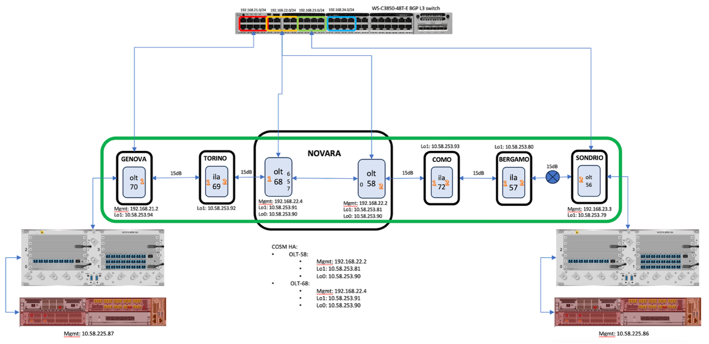
Prerequisites

Collect the required addressing and host information for each node in the topology.

Required details to gather before installation for each node in the topology.

  • Hostname for each node.

  • Management and loopback IP addresses.

  • Indicate the node role, such as OLT, ILA, OLA, or transponder shelf.

  • DCN plans to ensure proper management connectivity.

  • Access to servers such as NTP, TACACS, and Smart Licensing for software downloads.

Figure 1. Sample topology addressing
Table 5. Sample topology addressing

Node type

Hostname

Mgmt0 IP

Mgmt2 IP

Loopback1 IP

(OSC/COSM)

Loopback0 IP

(COSM- HA)

NCS1K-OLT-C

onc-oltc-225-70

10.58.225.70

192.168.21.2

10.58.253.94

NCS1K-ILA-C

onc-ilac-225-69

10.58.225.69

10.58.253.92

NCS1K-OLT-C

onc-oltc-225-68

10.58.225.68

192.168.22.4

10.58.253.91

10.58.253.90

NCS1K-OLT-C

onc-oltc-225-58

10.58.253.58

192.168.22.2

10.58.253.81

10.58.253.90

NCS1K14

onc-kepler-225-87

10.58.225.87

NCS1K04

onc-bh-225-93

10.58.225.93

Management interface requirements

This table describes the data that must be confirmed before installation, along with its status and related notes.

Table 6. Data to confirm before installation

Item

Status

Notes

IP plan

Complete

Validated with design team

Hostname list

Complete

Aligned with naming standards


Note


Adjust the addressing table to match the customer topology.


Install Cisco NCS 1010, NCS 1014, and NCS 1004 hardware

Prepare the hardware so it is ready for initial configuration.

Use these hardware-installation tasks in sequence. Each linked procedure is kept as a separate task step in the child topics.

Before you begin

Verify that the rack, power, grounding, hardware placement, cabling, and passive-connection details meet the site design and Cisco installation requirements.

Procedure


Step 1

Prepare and install the NCS 1010 chassis and required modules for the site.

For more details, see Install the NCS 1010 chassis and modules.

Step 2

Connect the NCS 1010 chassis to the approved site power feed.

For more details, see Connect power to the NCS 1010.

Step 3

Install the NCS 1010 passive modules and breakout hardware from the site design.

For more details, see Install NCS 1010 passive modules.

Step 4

Prepare and install the NCS 1014 chassis and required modules for the site.

For more details, see Install the NCS 1014 chassis and modules.

Step 5

Install NCS 1014 power components, pluggables, and air-filter hardware.

For more details, see Complete NCS 1014 power, pluggables, and air-filter installation.

Step 6

Prepare and install the NCS 1004 chassis in the site rack.

For more details, see Install the NCS 1004 chassis.

Step 7

Install the NCS 1004 controller and line cards required by the bill of materials.

For more details, see Install NCS 1004 controller and line cards.

Step 8

Install the NCS 1004 FRUs, pluggables, air filter, and fiber-management hardware.

For more details, see Install NCS 1004 field-replaceable units and fiber management.

Step 9

Connect NCS 1004 power and complete final fiber and passive connections.

For more details, see Connect NCS 1004 power and complete passive connections.


All hardware is installed and ready for console access and initial configuration.

Install the NCS 1010 chassis and modules

Install the NCS 1010 chassis and field-replaceable modules required for the site.

Complete these procedures before applying site power or completing passive-module connections.

Before you begin

Verify rack space, grounding, and site installation readiness for NCS 1010.

Procedure


Step 1

Verify rack space, grounding, airflow, tools, and safety requirements before installing Cisco NCS 1010.

For more details, see Prepare to install Cisco NCS 1010.

Step 2

Mount the Cisco NCS 1010 chassis in the approved EIA, ANSI, or ETSI rack.

For more details, see Install Cisco NCS 1010 on an EIA, ANSI, or ETSI rack.

Step 3

Install the required Cisco NCS 1010 modules in their assigned chassis slots.

For more details, see Install Cisco NCS 1010 modules.

Step 4

Insert and seat the NCS 1010 power supply unit in the assigned slot.

For more details, see Install PSU.

Step 5

Install and secure the NCS 1010 controller card.

For more details, see Install controller.

Step 6

Install and secure the required NCS 1010 line card.

For more details, see Install line card.

Step 7

Install the fan tray and confirm it is fully seated.

For more details, see Install fan tray.

Step 8

Install the fan filter after the fan tray is in place.

For more details, see Install fan filter.

Step 9

Install the protection cover as required by the hardware procedure.

For more details, see Install the protection cover.


The NCS 1010 chassis and modules are installed.

Connect power to the NCS 1010

Connect AC or DC power to the NCS 1010 chassis.

Select the procedure that matches the power design for the site.

Before you begin

Install the NCS 1010 chassis, PSU, and required protection hardware.

Procedure


Step 1

Connect the NCS 1010 chassis to the approved AC power source when the site uses AC feeds.

For more details, see Connect AC power to Cisco NCS 1010.

Step 2

Connect the NCS 1010 chassis to the approved DC power source when the site uses DC feeds.

For more details, see Connect DC power to Cisco NCS 1010.


Power connections for NCS 1010 are complete.

Install NCS 1010 passive modules

Install passive modules and breakout patch panels according to the site design.

Confirm module placement, port labels, and LED states before completing fiber connections.

Before you begin

Review the CONP design for required passive modules and breakout patch panels.

Procedure


Step 1

Identify the breakout patch panels and passive modules required for the NCS 1010 site.

For more details, see Cisco NCS 1000 breakout patch panel and modules overview.

Step 2

Install the Cisco NCS 1000 breakout patch panel in the planned location.

For more details, see Cisco NCS 1000 breakout patch panel.

Step 3

Install the Cisco NCS 1000 breakout modules required by the site design.

For more details, see Cisco NCS 1000 breakout modules.

Step 4

Match breakout module port labels to the cabling plan before connecting fibers.

For more details, see Breakout modules port label descriptions.

Step 5

Check breakout module LED states after installing and cabling the passive modules.

For more details, see Breakout module LEDs.


NCS 1010 passive module references are reviewed and the passive hardware can be installed according to the site design.

Install the NCS 1014 chassis and modules

Install the NCS 1014 chassis and core modules required for the OAS site.

Complete these procedures before power, pluggable, and air-filter installation.

Before you begin

Verify rack, power, grounding, and fiber-management readiness for NCS 1014.

Procedure


Step 1

Mount the Cisco NCS 1014 chassis in the approved EIA, ANSI, or ETSI rack.

For more details, see Install the Cisco NCS 1014 chassis on an EIA, ANSI, or ETSI rack.

Step 2

Confirm NCS 1014 power and grounding requirements before installing powered components.

For more details, see General power and grounding requirements.

Step 3

Attach the fiber management bracket to the slider rail before routing fibers.

For more details, see Attach the fiber management bracket to the slider rail.

Step 4

Install the SSD in the NCS 1014 chassis.

For more details, see Install the solid state drive (SSD).

Step 5

Install the fan unit and confirm it is fully seated.

For more details, see Install the fan unit.

Step 6

Install and secure the NCS 1014 controller.

For more details, see Install the controller.

Step 7

Attach the fiber management bracket for the installed module layout.

For more details, see Attach the fiber management bracket.

Step 8

Adjust the fiber management bracket for the planned fiber routing.

For more details, see Adjust the fiber management bracket.

Step 9

Install and secure the required NCS 1014 line card.

For more details, see Install the line card.


The NCS 1014 chassis and core modules are installed.

Complete NCS 1014 power, pluggables, and air-filter installation

Complete the remaining NCS 1014 hardware installation after the chassis and core modules are installed.

Select the AC or DC power procedure that matches the site design.

Before you begin

Install the NCS 1014 chassis, controller, fan unit, and line cards.

Procedure


Step 1

Install the NCS 1014 power supply units in the assigned slots.

For more details, see Install the power supply units (PSUs).

Step 2

Connect the NCS 1014 chassis to the approved DC power source when the site uses DC feeds.

For more details, see Connect DC power to the Cisco NCS 1014 chassis.

Step 3

Connect the NCS 1014 chassis to the approved AC power source when the site uses AC feeds.

For more details, see Connect AC power to the Cisco NCS 1014 chassis.

Step 4

Install the required pluggables in the NCS 1014 ports.

For more details, see Install the pluggables.

Step 5

Install the NCS 1014 air filter after module installation is complete.

For more details, see Install the air filter.


NCS 1014 power, pluggables, and air-filter installation is complete.

Install the NCS 1004 chassis

Install the NCS 1004 chassis according to site rack and grounding requirements.

Complete chassis installation before installing controllers, line cards, and field-replaceable units.

Before you begin

Verify rack compatibility, grounding, and power-feed readiness for NCS 1004.

Procedure


Step 1

Confirm that the site rack supports the NCS 1004 chassis before installation.

For more details, see Rack compatibility.

Step 2

Mount the NCS 1004 chassis in the approved EIA, ANSI, or ETSI rack.

For more details, see Install NCS 1004 on an EIA, ANSI, or ETSI rack.

Step 3

Apply the NCS 1004 stacking requirements if multiple chassis share the rack space.

For more details, see Stacking NCS 1004.

Step 4

Confirm NCS 1004 power and grounding requirements before installing powered components.

For more details, see General power and grounding requirements.

Step 5

Verify the NCS 1004 power supply type against the site power design.

For more details, see Power supply.


The NCS 1004 chassis is installed and ready for module installation.

Install NCS 1004 controller and line cards

Prepare and install the NCS 1004 controller and supported line-card hardware.

Use the line-card-specific references that match the hardware in the site bill of materials.

Before you begin

Install the NCS 1004 chassis.

Procedure


Step 1

Review the NCS 1004 module installation sequence before inserting cards.

For more details, see Install Cisco NCS 1004 modules.

Step 2

Confirm that the controller card is supported for the NCS 1004 chassis.

For more details, see Supported controller cards.

Step 3

Install and secure the NCS 1004 controller card.

For more details, see Install controller.

Step 4

Identify the NCS 1004 line-card type required by the site bill of materials.

For more details, see About line cards.

Step 5

Use the 1.2T line-card requirements when the site includes a 1.2T card.

For more details, see 1.2T line card.

Step 6

Use the 1.2TL line-card requirements when the site includes a 1.2TL card.

For more details, see 1.2TL line card.

Step 7

Use the 2-QDD-C line-card requirements when the site includes a 2-QDD-C card.

For more details, see 2-QDD-C line card.

Step 8

Use the OTN-XP line-card requirements when the site includes an OTN-XP card.

For more details, see OTN-XP line card.

Step 9

Use the QXP-K9 line-card requirements when the site includes a QXP-K9 card.

For more details, see QXP-K9 line card.


The NCS 1004 controller and line-card references are complete for the installed hardware.

Install NCS 1004 field-replaceable units and fiber management

Complete NCS 1004 module, field-replaceable unit, pluggable, air-filter, and fiber-management installation.

Use the fiber-management procedure that matches the installed line-card type.

Before you begin

Install the NCS 1004 chassis and identify the installed line-card type.

Procedure


Step 1

Insert and secure the selected NCS 1004 line card in the assigned slot.

For more details, see Install line card.

Step 2

Install the NCS 1004 power supply in the assigned slot.

For more details, see Install power supply.

Step 3

Install the fan unit and confirm it is fully seated.

For more details, see Install fan unit.

Step 4

Attach the fiber management bracket before routing fibers to the line cards.

For more details, see Attach fiber management bracket.

Step 5

Adjust fiber management for installed 1.2T, 1.2TL, 2-QDD-C, or QXP-K9 line cards.

For more details, see Adjust fiber management bracket of the 1.2T, 1.2TL, 2-QDD-C, and QXP-K9 line cards.

Step 6

Adjust fiber management for an installed OTN-XP line card.

For more details, see Adjust fiber management bracket of the OTN-XP line card.

Step 7

Install the required pluggables in the NCS 1004 ports.

For more details, see Install pluggables.

Step 8

Confirm the NCS 1004 air-filter requirements for the installed chassis.

For more details, see Air filter.

Step 9

Install the NCS 1004 air filter.

For more details, see Install air filter.


The NCS 1004 field-replaceable units, pluggables, air filter, and fiber-management hardware are installed.

Connect NCS 1004 power and complete passive connections

Complete NCS 1004 power connections and final OAS fiber and passive connections.

Complete all fiber and port connections according to the network design. Use the Brk-8 module for internal degree connections when required. Based on the design, internal degree connections can also be established directly through LC ports instead of through the Brk-8 module.

Before you begin

Install the required NCS 1004 modules and review the CONP design output for site passive connections.

Procedure


Step 1

Connect the NCS 1004 chassis to the approved DC power source when the site uses DC feeds.

For more details, see Connect DC power to NCS 1004.

Step 2

Connect the NCS 1004 chassis to the approved AC power source when the site uses AC feeds.

For more details, see Connect AC power to NCS 1004.

Step 3

Use the CONP NFV and connection reports to complete passive and fiber connections.

For more details, see Review the CONP NFV and connection reports.


NCS 1004 power and final site passive connections are complete.

What to do next

Proceed to day-0 configuration for each node.

NCS 1010 setup and initial configuration

This subsection covers the essential steps to prepare and configure the NCS 1010 device for operation.

  • Boot the chassis and access the XR console.

  • Complete day-0 configuration using the recommended manual approach or ZTP.

  • Configure management, loopback, and neighbor interfaces based on the topology.

NCS1010 bootup process

After installing the hardware, boot the Cisco NCS 1010 system. Connect to the XR console port and power on the system. NCS 1010 completes the boot process using the pre-installed OS image. If no image is available, NCS 1010 can be booted using iPXE or an external bootable USB drive.

Use any one of the tasks to boot the NCS 1010 chassis.

Once booted, please verify the system using the steps in the Cisco NCS 1010 Deployment Guide.

Configure NCS 1010 day-0 settings

Prepare the NCS 1010 for day-1 configuration and network onboarding by completing the day-0 sub tasks.

Procedure


Step 1

Complete the manual bring-up workflow.

See Manually bring up NCS1000.

Step 2

Configure NTP for time synchronization.

See NTP server configuration.

Step 3

Configure SNMP if monitoring is required.

See SNMP configuration (optional).


Manually bring up NCS1010, NCS1014, and NCS1004

Complete the manual day-0 bring-up for NCS1010, NCS1014, and NCS1004 by following the prerequisite setup and configuration tasks in sequence.

NCS1010 supports two different approaches for bring-up: manual and ZTP. This workflow covers the manual approach.

Before you begin

  • Ensure that the NCS 1010 bring-up configuration is completed on all nodes in the topology before proceeding with this section.

  • The interfaces come up only after the configuration is applied across all nodes and the fiber connections are completed correctly.

Follow these steps to complete the manual day-0 bring-up for NCS 1010, NCS 1014, and NCS 1004.

Procedure

Step 1

Complete prerequisites and access setup.

See Prepare access and initial credentials.

Step 2

Configure management and loopback addressing.

See Configure management and loopback addressing.

Step 3

Configure OSPF and verify neighbors.

See Configure OSPF and verify neighbors.

Step 4

Configure routing policies and BGP, then update OSPF.

See Configure routing policies, static routes, and BGP.

Step 5

Validate controllers, alarms, and span loss.

See Validate controllers and alarms.


The NCS1010/NCS1014/NCS1004 system is brought up to day-0 configuration and ready for downstream workflows.

Prepare access and initial credentials on NCS1010

Establish console access, set root credentials, and apply a hostname so the node can be configured.

Follow these steps to prepare access and initial credentials on the node.

Procedure

Step 1

Configure DHCP settings if required for IP address assignment.

A DHCP server is required for this configuration.

For more details, see Cisco NCS 1010 Deployment Guide, Cisco IOS XR Releases.

Step 2

Connect to the node through the console port, configure the root-system username, and use these credentials to log in later.

Example:

          ---------------------
Enter root-system username: xxxxxx
Enter secret:
Enter secret again:
Use the 'configure' command to modify this configuration.
User Access Verification
Username:
Password: xxxxxx
---------------------
          

Step 3

Assign a hostname to the node.

Example:

RP/0/RP0/CPU0:ios#config
RP/0/RP0/CPU0:ios(config)#hostname onc-oltc-225-70
RP/0/RP0/CPU0:ios(config)#commit
RP/0/RP0/CPU0:ios(config)#end
          

The node is accessible with root credentials and has a hostname assigned.

What to do next

Next, complete Configure management and loopback addressing.

Configure management and loopback addressing

Assign management and loopback IP addressing and verify interface status before and after addressing.

Before you begin

Follow these steps to configure management and loopback addressing.

Procedure

Step 1

View the interface status before addressing.

Example:

RP/0/RP0/CPU0:onc-oltc-225-70#show ipv4 interface brief
          
Table 7. Interface status before addressing

Interface

IP-Address

Status

Protocol

Vrf-Name

Loopback1

unassigned

Down

Down

default

GigabitEthernet0/0/0/0

unassigned

Down

Down

default

MgmtEth0/RP0/CPU0/0

unassigned

Down

Down

default

PTP0/RP0/CPU0/0

unassigned

Down

Down

default

MgmtEth0/RP0/CPU0/1

unassigned

Down

Down

default

PTP0/RP0/CPU0/1

unassigned

Down

Down

default

MgmtEth0/RP0/CPU0/2

unassigned

Down

Down

default

MgmtEth0/RP0/RCOM0/0

unassigned

Down

Down

default

Step 2

Assign IP addresses for management, GigabitEthernet, and Loopback interfaces based on the addressing plan.

Example:

RP/0/RP0/CPU0:onc-oltc-225-70#configure
RP/0/RP0/CPU0:onc-oltc-225-70(config)#interface Loopback1
RP/0/RP0/CPU0:onc-oltc-225-70(config-if)# ipv4 address 10.58.253.94 255.255.255.255
RP/0/RP0/CPU0:onc-oltc-225-70(config-if)# interface MgmtEth0/RP0/CPU0/0
RP/0/RP0/CPU0:onc-oltc-225-70(config-if)# ipv4 address 10.58.225.70 255.255.255.0
          

Step 3

Configure the management interface.

Example:

RP/0/RP0/CPU0:onc-oltc-225-70(config-if)#interface MgmtEth0/RP0/CPU0/2
RP/0/RP0/CPU0:onc-oltc-225-70(config-if)# ipv4 address 192.168.21.2 255.255.255.0
          

These items outline the management interface design choices by node type for this topology document

  • OLT: MgmtEth0/RP0/CPU0/2 required for DHCP relay and remote management.

  • ILA: MgmtEth0/RP0/CPU0/2 required for neighbor connectivity.

This table describes the management interface requirements:

Table 8. Interface requirements

Node type

MgmtEth0/RP0/CPU0/2

Required

Purpose

OLT

Yes

Required

DHCP relay and remote management

ILA

Yes

Required

Neighbor connectivity

TXP shelves

No

Not required

Not applicable

Step 4

Configure loopback addresses on both NCS 1010 OLTs participating in Cisco Optical Site Manager HA.

Example:

RP/0/RP0/CPU0:onc-oltc-225-58(config)#interface Loopback0
RP/0/RP0/CPU0:onc-oltc-225-58(config-if)#ipv4 address 10.58.253.90 255.255.255.255
RP/0/RP0/CPU0:onc-oltc-225-68(config)#interface Loopback0
RP/0/RP0/CPU0:onc-oltc-225-68(config-if)#ipv4 address 10.58.253.90 255.255.255.255
          
Example:

Note


These IP address should be same on the NCS 1010 HA hosts.

Step 5

Configure neighbor connectivity for OLT and ILA nodes.

Not required for TXP shelves for NCS 1014 and NCS 1004.

Example:

RP/0/RP0/CPU0:onc-oltc-225-70(config-if)#interface GigabitEthernet0/0/0/0
RP/0/RP0/CPU0:onc-oltc-225-70(config-if)# ipv4 point-to-point
RP/0/RP0/CPU0:onc-oltc-225-70(config-if)# ipv4 unnumbered Loopback1
RP/0/RP0/CPU0:onc-oltc-225-70(config-if)# lldp
RP/0/RP0/CPU0:onc-oltc-225-70(config-lldp)#  enable
RP/0/RP0/CPU0:onc-oltc-225-70(config-lldp)#  commit
          

Step 6

For ILA nodes, configure the second neighbor interface.

Example:

RP/0/RP0/CPU0:onc-ilac-225-69(config-if)#interface GigabitEthernet0/0/0/2
RP/0/RP0/CPU0:onc-ilac-225-69(config-if)# ipv4 point-to-point
RP/0/RP0/CPU0:onc-ilac-225-69 (config-if)# ipv4 unnumbered Loopback1
RP/0/RP0/CPU0:onc-ilac-225-69 (config-if)# lldp
RP/0/RP0/CPU0:onc-ilac-225-69 (config-lldp)#  enable
RP/0/RP0/CPU0:onc-ilac-225-69 (config-lldp)#  commit
RP/0/RP0/CPU0:onc-ilac-225-69 (config-lldp)#  end
          

Step 7

View the interface status after addressing.

Example:

RP/0/RP0/CPU0:onc-oltc-225-70#show ipv4 interface brief
          
Table 9. Interface status after addressing

Interface

IP-Address

Status

Protocol

Vrf-Name

Loopback1

10.58.253.94

Up

Up

Default

GigabitEthernet0/0/0/0

10.58.253.94

Up

Up

Default

MgmtEth0/RP0/CPU0/0

10.58.225.70

Up

Up

Default

PTP0/RP0/CPU0/0

unassigned

Down

Down

Default

MgmtEth0/RP0/CPU0/1

unassigned

Down

Down

Default

PTP0/RP0/CPU0/1

unassigned

Down

Down

Default

MgmtEth0/RP0/CPU0/2

192.168.21.2

Up

Up

Default

MgmtEth0/RP0/RCOM0/0

unassigned

Down

Down

Default

Step 8

Configure SSH (secure shell).

Example:

RP/0/RP0/CPU0:onc-oltc-225-70(config)#config
RP/0/RP0/CPU0:onc-oltc-225-70(config)#ssh server rate-limit 600
RP/0/RP0/CPU0:onc-oltc-225-70(config)#ssh server session-limit 110
RP/0/RP0/CPU0:onc-oltc-225-70(config)#ssh server v2
RP/0/RP0/CPU0:onc-oltc-225-70(config)#ssh server vrf default
RP/0/RP0/CPU0:onc-oltc-225-70(config)#ssh server netconf vrf default
RP/0/RP0/CPU0:onc-oltc-225-70(config)#commit
          

Step 9

Configure NETCONF-YANG over SSH to enable device management by Cisco Optical Site Manager.

Example:

RP/0/RP0/CPU0:onc-oltc-225-70(config)#netconf agent tty
RP/0/RP0/CPU0:onc-oltc-225-70(config-netconf-tty)#netconf-yang agent
RP/0/RP0/CPU0:onc-oltc-225-70(config-ncy-agent)# ssh
RP/0/RP0/CPU0:onc-oltc-225-70(config)#commit
          

IP addresses are assigned to the management and loopback interfaces.

What to do next

Next, complete Configure OSPF and verify neighbors.

Configure OSPF and verify neighbors

Configure OSPF on OLT and ILA nodes and verify neighbor adjacencies. The neighbours are visible only after the configuration is applied across all nodes and the fiber connections are completed correctly.

Follow these steps to configure OSPF and verify neighbors.

Procedure

Step 1

Configure OSPF in NCS1010 OLT nodes.

Example:
RP/0/RP0/CPU0:onc-oltc-225-70(config)#router ospf 1
RP/0/RP0/CPU0:onc-oltc-225-70(config-ospf)# distribute link-state
RP/0/RP0/CPU0:onc-oltc-225-70(config-ospf)# router-id 10.58.253.94
RP/0/RP0/CPU0:onc-oltc-225-70(config-ospf)# network point-to-point
RP/0/RP0/CPU0:onc-oltc-225-70(config-ospf)# area 0
RP/0/RP0/CPU0:onc-oltc-225-70(config-ospf-ar)#  interface Loopback1
RP/0/RP0/CPU0:onc-oltc-225-70(config-ospf-ar-if)#  interface GigabitEthernet0/0/0/0    
RP/0/RP0/CPU0:onc-oltc-225-70(config-ospf-ar-if)#commit
RP/0/RP0/CPU0:onc-oltc-225-70(config-ospf-ar-if)# end
          

Note


router-id must be modified for each node.

Step 2

Configuring OSPF settings for the interface on the ILA node and commit the changes.

Example:
RP/0/RP0/CPU0:onc-oltc-225-70(config)#router ospf 1
RP/0/RP0/CPU0:onc-oltc-225-70(config-ospf)# distribute link-state
RP/0/RP0/CPU0:onc-oltc-225-70(config-ospf)# router-id 10.58.253.94
RP/0/RP0/CPU0:onc-oltc-225-70(config-ospf)# network point-to-point
RP/0/RP0/CPU0:onc-oltc-225-70(config-ospf)# area 0
RP/0/RP0/CPU0:onc-oltc-225-70(config-ospf-ar)#  interface Loopback1
RP/0/RP0/CPU0:onc-oltc-225-70(config-ospf-ar-if)#  interface GigabitEthernet0/0/0/0    
RP/0/RP0/CPU0: onc-ilac-225-69(config-ospf-ar-if)#  interface GigabitEthernet0/0/0/2
RP/0/RP0/CPU0:onc-oltc-225-70(config-ospf-ar-if)#commit
RP/0/RP0/CPU0:onc-oltc-225-70(config-ospf-ar-if)# end

Note


router-id must be modified for each node.

Step 3

View OSPF neighbors using the show ospf neighbor command.

Example:

RP/0/RP0/CPU0:OLT-R-C-SITE-4#show ospf neighbor 
Mon Jul 25 09:22:58.684 UTC

* Indicates MADJ interface
# Indicates Neighbor awaiting BFD session up
Neighbors for OSPF 1
Total neighbor count: 2


Neighbor ID     Pri    State           Dead Time   Address              Interface
10.58.253.94     1     FULL/  -        00:00:38    10.58.253.94        GigabitEthernet0/0/0/0
    Neighbor is up for 1w1d
10.58.253.91     1     FULL/  -        00:00:38    10.58.253.91        GigabitEthernet0/0/0/2
    Neighbor is up for 3d06h
          

OSPF is configured and neighbor adjacency is verified.

What to do next

Next, complete Configure routing policies, static routes, and BGP.

Configure routing policies, static routes, and BGP

Configure routing policy, static routes, and BGP (OLT only), then update OSPF redistribution.

Before you begin

Follow these steps to configure routing policies and BGP, then update OSPF.

Procedure

Step 1

Configure route policy and static routes on OLT and ILA nodes.

Example:

RP/0/RP0/CPU0:onc-oltc-225-70#config
RP/0/RP0/CPU0:onc-oltc-225-70(config)#route-policy pass-all
RP/0/RP0/CPU0:onc-oltc-225-70(config-rpl)# pass    
RP/0/RP0/CPU0:onc-oltc-225-70(config-rpl)#end-policy
RP/0/RP0/CPU0:onc-oltc-225-70(config)#router static
RP/0/RP0/CPU0:onc-oltc-225-70(config-static)# address-family ipv4 unicast
RP/0/RP0/CPU0:onc-oltc-225-70(config-static-afi)# 0.0.0.0/0 10.58.225.1
RP/0/RP0/CPU0:onc-oltc-225-70(config-static-afi)# 10.58.251.0/24 10.58.253.1
          

Step 2

Configure BGP for SSH connectivity from DCN on OLT nodes only.

Example:

RP/0/RP0/CPU0:onc-oltc-225-70(config)#router bgp 1
RP/0/RP0/CPU0:onc-oltc-225-70(config-bgp)# bgp router-id 10.58.253.94
RP/0/RP0/CPU0:onc-oltc-225-70(config-bgp)# address-family ipv4 unicast
RP/0/RP0/CPU0:onc-oltc-225-70(config-bgp-af)#  redistribute connected
RP/0/RP0/CPU0:onc-oltc-225-70(config-bgp-af)#  redistribute ospf 1 route-policy pass-all
RP/0/RP0/CPU0:onc-oltc-225-70(config-bgp-af)#neighbor 192.168.21.1
RP/0/RP0/CPU0:onc-oltc-225-70(config-bgp-nbr)#  remote-as 100
RP/0/RP0/CPU0:onc-oltc-225-70(config-bgp-nbr)#  address-family ipv4 unicast
RP/0/RP0/CPU0:onc-oltc-225-70(config-bgp-nbr-af)#   route-policy pass-all in
RP/0/RP0/CPU0:onc-oltc-225-70(config-bgp-nbr-af)#   route-policy pass-all out
          

Step 3

Redistribute routes between OSPF and BGP.

Example:

RP/0/RP0/CPU0:onc-oltc-225-70(config-bgp-nbr-af)#router ospf 1
RP/0/RP0/CPU0:onc-oltc-225-70(config-ospf)# default-information originate
RP/0/RP0/CPU0:onc-oltc-225-70(config-ospf)# redistribute connected
RP/0/RP0/CPU0:onc-oltc-225-70(config-ospf)# redistribute bgp 1 route-policy pass-all
RP/0/RP0/CPU0:onc-oltc-225-70(config-ospf)# commit
          

Routing policy, static routes, and BGP are configured and OSPF redistribution is updated.

What to do next

Next, complete Validate controllers and alarms.

Validate controllers and alarms

Validate controller status, review alarms, and confirm span-loss after bring-up.

Before you begin

Follow these steps to validate controllers and alarms.

Procedure

Step 1

Verify the OSC Controller State is UP.

For ILA nodes, check both controllers.

Example:

RP/0/RP0/CPU0:onc-ilac-225-69#show controllers osc 0/0/0/0
Controller State: Up
Transport Admin State: In Service
Laser State: On
Last link flapped: 1w1d
Alarm Status:
-------------
Detected Alarms: None

Alarm Statistics:
-----------------
RX-LOS-P = 0
TX-POWER-FAIL-LOW = 0

Parameter Statistics:
---------------------
Total Tx Power = -7.92 dBm
Total Rx Power = -22.88 dBm
OSNR = 41.50 dB
RP/0/RP0/CPU0:onc-ilac-225-69#show controllers osc 0/0/0/2

Step 2

Check for active alarms and refer to the troubleshooting guide to clear them if necessary.

Example:

          RP/0/RP0/CPU0:onc-ilac-225-69#sh alarms brief system active
------------------------------------------------------------------------------------
Active Alarms
------------------------------------------------------------------------------------
Location        Severity     Group            Set Time                   Description
------------------------------------------------------------------------------------
0/PM1           Major        Environ          09/19/2025 13:29:25 UTC    Power Module Error (PM_VIN_VOLT_OOR)
0/PM1           Major        Environ          09/19/2025 13:29:25 UTC    Power Module Output Disabled (PM_OUTPUT_DISABLED)
0               Major        Environ          09/19/2025 13:29:25 UTC    Power Group Redundancy lost
0/RP0/CPU0      Minor        Software         09/19/2025 13:31:02 UTC    SW Upgrade is still allowed as SIA Grace Period is remaining
0/RP0/CPU0      Major        Software         09/19/2025 13:31:05 UTC    Communications Failure With Cisco Licensing Cloud
0/0/NXR0        Minor        Software         11/22/2025 11:50:38 UTC    Ots0/0/0/0 - Span Loss Value Out Of Range
0/0/NXR0        Minor        Software         11/24/2025 12:15:35 UTC    Ots0/0/0/2 - Span Loss Value Out Of Range
          

Step 3

Verify SSH connectivity to all nodes and check span loss after neighbor or full topology bring-up.

Example:

          RP/0/RP0/CPU0:onc-ilac-225-69#sh olc span-loss
------------------------------------------------------
Controller                                : Ots0/0/0/0
Neighbour RID                             : 10.58.253.94
Rx Span Loss                              : 14.62 dB
Rx OSC Span Loss                          : 14.91 dB
Rx Signal Span Loss                       : 14.62 dB
Rx Span Loss (with pumps off)             : NA
Estimated Rx Span Loss                    : NA
Tx Span Loss                              : 14.96 dB
Tx OSC Span Loss                          : 15.02 dB
Tx Signal Span Loss                       : 14.96 dB
Tx Span Loss (with pumps off)             : NA
Estimated Tx Span Loss                    : NA

Controller                                : Ots0/0/0/2
Neighbour RID                             : 10.58.253.91
Rx Span Loss                              : 14.41 dB
Rx OSC Span Loss                          : 14.59 dB
Rx Signal Span Loss                       : 14.41 dB
Rx Span Loss (with pumps off)             : NA
Estimated Rx Span Loss                    : NA
Tx Span Loss                              : 15.48 dB
Tx OSC Span Loss                          : 15.17 dB
Tx Signal Span Loss                       : 15.48 dB
Tx Span Loss (with pumps off)             : NA
Estimated Tx Span Loss                    : NA
          

Controllers are up, alarms are reviewed, and span-loss is validated.

NTP server configuration

NTP uses the User Datagram Protocol (UDP) as its transport protocol. All NTP communication uses Coordinated Universal Time (UTC). An NTP network usually receives its time from an authoritative time source, such as a radio clock or an atomic clock attached to a time server. NTP distributes this time across the network.

An NTP broadcast client listens for broadcast messages sent by an NTP broadcast server at a designated IPv4 address. The client synchronizes the local clock using the first received broadcast message.

Below are the steps for NTP configuration:

Procedure

Step 1

Synchronize Clock with NTP Server

Step 2

Verify the Status of the External Reference Clock


What to do next

Troubleshoot NTP Issues

SNMP configuration (optional)

SNMP is a framework that provides facilities for managing and monitoring network resources on the Internet. SNMP uses UDP for transport and uses port 161 for SNMP messages like walk and 162 for traps. This document lists the SNMP configuration(s) for monitoring the network if needed by the customer. SNMPv3 for walk and SNMP v2c for traps is covered.

Procedure

Step 1

Review the SNMP procedures and supported MIBs.

The procedure to configure SNMP on a 1010 device, along with the supported MIBS can be found Configuring SNMP.

Step 2

Set up SNMPv3 for secure access.

SNMPv3 is the most secure version of the protocol and setting it up can be found in the Setup SNMP Version 3.

For retrieving information from the device using snmpwalk, the following configurations are required.

Step 3

Configure the SNMP view.

Setup SNMP View: The Setup SNMP view command can block the user with only access to limited Management Information Base (MIB). By default, there is no SNMP view entry exists.

Example:
RP/0/RP0/CPU0:onc-oltc-225-70(config)#snmp-server view testview 1.3.6.1.2 included
RP/0/RP0/CPU0:onc-oltc-225-70(config)#snmp-server view testview ospf excluded

Step 4

Create an SNMP group and users.

Create snmp-server group: Create a group to map users with views.

Example:
RP/0/RP0/CPU0:onc-oltc-225-70(config)#snmp-server group testgroup v3 priv notify testview read testview

Create snmp users and assign to group.

Example:
RP/0/RP0/CPU0:onc-oltc-225-70(config)#snmp-server user snmpuser testgroup v3 auth sha <authpassword> priv aes 128 <privpassword>

Step 5

Verify SNMP configuration and optional tuning.

Note: The show running config shows additional key word encrypted for the passwords, followed by encrypted passwords.

Example:
RP/0/RP0/CPU0:onc-oltc-225-70#sh run snmp
snmp-server user snmpuser testgroup v3 auth sha encrypted 01100F175804575D72 priv aes 128 encrypted 110A1016141D595F50

Below additional configurations are typically used to ensure the queries don’t overload the system and also to retrieve information for long names.

Example:
RP/0/RP0/CPU0:onc-oltc-225-70(config)#snmp-server ifmib ifalias long
RP/0/RP0/CPU0:onc-oltc-225-70(config)#snmp-server ifindex persist
RP/0/RP0/CPU0:onc-oltc-225-70(config)#snmp-server ifmib stats cache
RP/0/RP0/CPU0:onc-oltc-225-70(config)#snmp-server logging threshold
RP/0/RP0/CPU0:onc-oltc-225-70(config)#oid-processing 1000
RP/0/RP0/CPU0:onc-oltc-225-70(config)#snmp-server logging threshold pdu-processing 2000

Sample configuration for SNMPwalk from the server.

Example:
snmpwalk -v3 -u snmpuser -l authpriv -a sha -A <authpassword> -x AES -X <privpassword> 10.78.60.234 .1.3.6.1.2
SNMPv2-MIB::sysDescr.0 = STRING: Cisco IOS XR Software, Version 25.1.1                                                                                                                                                 
 (NCS1010)                                                                                                                                                                                                             
Copyright (c) 2013-2025 by Cisco Systems, Inc.                                                                                                                                                                         
SNMPv2-MIB::sysObjectID.0 = OID: CISCO-SMI::ciscoProducts.3153                                                                                                                                                         
DISMAN-EVENT-MIB::sysUpTimeInstance = Timeticks: (38083) 0:06:20.83                                                                                                                                                    
SNMPv2-MIB::sysContact.0 = STRING: sirius-dt@cisco.com                                                                                                                                                                 
SNMPv2-MIB::sysName.0 = STRING: ios                                                                                                                                                                                    
SNMPv2-MIB::sysLocation.0 = STRING: IN, BGL-17-4-Y BLR [12.9629, 77.5775]                                                                                                                                              
SNMPv2-MIB::sysServices.0 = INTEGER: 78                                                                                                                                                                                
IF-MIB::ifNumber.0 = INTEGER: 16                                                                                                                                                                                       
IF-MIB::ifIndex.2 = INTEGER: 2                                                                                                                                                                                         
IF-MIB::ifIndex.3 = INTEGER: 3                                                                                                                                                                                         
IF-MIB::ifIndex.4 = INTEGER: 4
………….
………..

Step 6

Configure SNMP traps.

For receiving the automatic notifications from the device via snmp traps the following configurations are required as mentioned in SNMP Traps.

Different types of traps can be enabled. Trap types include alarms, configuration changes, authentication framework events, IEEE 802.1X events, and many Cisco-specific notifications.

Sample examples:

Example:
RP/0/RP0/CPU0:ios(config)#snmp-server traps alarm
RP/0/RP0/CPU0:ios(config)#snmp-server traps power
RP/0/RP0/CPU0:ios(config)#snmp-server traps config
RP/0/RP0/CPU0:ios(config)#snmp-server traps optical
RP/0/RP0/CPU0:ios(config)#snmp-server traps optical-ots

For V3 traps, server IP, userid and UDP port are needed as in the example given below.

Example:
RP/0/RP0/CPU0:ios(config)#snmp-server host <server-ip> traps version 3 priv <userid> udp-port <port#>

For V2 traps, server IP, protocol 2c, community name and UDP ports are needed.

Example:
RP/0/RP0/CPU0:ios(config)#snmp-server host <server-ip> traps version 2c public udp-port <port#>
RP/0/RP0/CPU0:ios(config)#snmp-server community snmpcommunity RO

The following output shows an SNMP trap received after the listener starts waiting for traps:


Received SNMPv2c Trap:                                                                                                                                                                                                 
Community: snmpcommunity                                                                                                                                                                                                      
From: 10.78.60.234                                                                                                                                                                                                     
sysUpTimeInstance = 01:13:42.70                                                                                                                                                                                        
snmpTrapOID.0 = clogMessageGenerated                                                                                                                                                                                   
clogHistFacility.0 = SECURITY-SSHD_SYSLOG_PRX                                                                                                                                                                          
clogHistSeverity.0 = info(7)                                                                                                                                                                                           
clogHistMsgName.0 = INFO_GENERAL                                                                                                                                                                                       
clogHistMsgText.0 = sshd[64262]: Connection closed by 10.78.60.234 port 58463                                                                                                                                          
clogHistTimestamp.0 = 01:13:42.00                                                                                                                                                                                      

Received SNMPv2c Trap:                                                                                                                                                                                                 
Community: public                                                                                                                                                                                                      
From: 10.78.60.234                                                                                                                                                                                                     
sysUpTimeInstance = 01:13:42.92                                                                                                                                                                                        
snmpTrapOID.0 = clogMessageGenerated                                                                                                                                                                                   
clogHistFacility.0 = SECURITY-SSHD_SYSLOG_PRX                                                                                                                                                                          
clogHistSeverity.0 = info(7)                                                                                                                                                                                           
clogHistMsgName.0 = INFO_GENERAL                                                                                                                                                                                       
clogHistMsgText.0 = sshd[64760]: Accepted authentication/pam for cisco from 10.78.60.234 port 58685 ssh2                                                                                                               
clogHistTimestamp.0 = 01:13:42.00 

Day-1 configuration

Direct operators to Cisco Optical Site Manager workflows for day-1 configuration tasks.

Day-1 configuration is performed in Cisco Optical Site Manager.

  • Follow the Cisco Optical Site Manager section for detailed workflows.

  • Ensure node credentials and IP addresses are available.

Typical day-1 activities.

  • Device onboarding and synchronization.

  • Topology and service configuration.

Validate the NCS 1010 setup

Confirm that software, hardware, and licensing are operational.

Perform these checks after initial configuration and before day-1 workflows.

Before you begin

Ensure the node is reachable and interfaces are up.

Procedure


Step 1

Verify Smart Licensing status.

Example:

show license status

Step 2

Run preliminary checks on the default setup.

Use the site checklist for preliminary validation items. Refer to preliminary checks for detailed procedures.

Step 3

Verify software and hardware status.

Example:

show platform
show inventory

The NCS 1010 is ready for operational use or day-1 configuration in Cisco Optical Site Manager (COSM).

Back up the current configuration

The ability to recover from a disaster is an essential part of any system maintenance plan. We recommend you backup the configurations in a secure remote location and verify that the transfer is a success, both before and after upgrade.

Before you begin

Verify connectivity to the local hard disk or remote server.

Procedure


Step 1

Copy the running configuration to the local hard disk.

Example:

RP/0/RP0/CPU0:ios#copy running-config harddisk:/running_config-<mmddyyyy>
Destination filename [running_config-<mmddyyyy>]?
Building configuration...
[OK]
Verifying checksum... OK

Step 2

Copy the configuration to a remote server.

Example:

RP/0/RP0/CPU0:ios#scp harddisk:/running_config-<mmddyyyy> <user>:<password>@<ip-address>:<location>

Step 3

Verify that the backup completed successfully.

Confirm the file exists on the local disk and the remote server.


The configuration backup is available for recovery if needed.

What to do next

Provide this information for Day1 configuration and to bring the network to operational IP’s of individual nodes with credentials.

Troubleshooting

Identify the correct troubleshooting guide based on the symptom.

Troubleshooting coverage areas.

  • Hardware alarms and platform issues.

  • Data path and optical application alarms.

  • Infrastructure alarms and system health.

Table 10. Troubleshooting entry points

Issue type

Primary guide

Troubleshoot NCS 1010 setup and upgrade

NCS 1010 troubleshoot guide

Data path alarms

Data path alarms guide

Optical application alarms

Optical application alarms guide

Infrastructure alarms

Infrastructure alarms guide

Table 11. Command quick reference

Command

Purpose

When to use

Notes

show alarms brief system active

Active alarms

During alarm triage

Check severity and timestamps

show controllers osc 0/0/0/0

Controller status

When OSC issues appear

Verify optical status

show olc span-loss

Span loss

After topology bring-up

Compare with design values

show ospf neighbor

OSPF adjacency

Neighbor device issues

Confirm adjacency state

Table 12. Alarm triage guide

Severity

Action

Notes

Major

Escalate

Follow hardware troubleshooting guide

Minor

Monitor

Review for recurring issues

Cisco IOS XR SMU installation procedures

Use the procedure that matches the software maintenance update workflow required for the selected Cisco IOS XR fixes.

You can install Cisco IOS XR SMUs by using a Golden ISO, the install source command, or the install package add source command. Use the method that matches the required fix and the reload control needed for the maintenance window.

Table 13. SMU installation procedures

Method

Use case

Procedure

Using a Golden ISO

Install the Cisco IOS XR software image and selected SMUs in one operation.

Install using a Golden ISO with bug fixes
Using the install source command

Install a software image or SMU package directly from a device path such as /harddisk:/.

Install using the install source command

Using the install package add source command

Install multiple SMUs together when control over reload timing is required.

Install additional RPMs and bug fixes

Install using a Golden ISO with bug fixes

Install a customized Golden ISO (GISO) that includes the Cisco IOS XR software image and selected SMUs in one operation.

A Golden ISO is a customized ISO that includes the standard base image with basic functional components, additional RPMs, SMUs, and configuration files as required. A Golden ISO upgrades the device to a version that has a predefined list of SMUs in a single operation.

Before you begin

  • Obtain the required Golden ISO for the device platform and Cisco IOS XR release.

  • Obtain the expected checksum for the Golden ISO.

  • Ensure that the device is reachable from the server that stores the Golden ISO.

  • Schedule a maintenance window because the installation can reload the device.

Procedure


Step 1

Verify the checksum of the downloaded Golden ISO, copy the image to the device hard disk, and confirm that the copied file is present.

Example:

server$ md5sum <giso-file>.iso
server$ scp <giso-file>.iso <username>@<device-ip>:/harddisk:/
RP/0/RP0/CPU0:router#run
[node0_RP0_CPU0:~]$ cd /harddisk\:
[node0_RP0_CPU0:/harddisk:]$ ls -ltra | grep -i <giso-file>.iso

Example from the OAS guide:

[syedsaah@vxr-sirius-04 Image]$ md5sum ncs1010-golden-x86_64-25.1.1-Feb27Drop2.iso
44dcd5214add0314116d109918bb926f  ncs1010-golden-x86_64-25.1.1-Feb27Drop2.iso
[syedsaah@vxr-sirius-04 Image]$ scp ncs1010-golden-x86_64-25.1.1-Feb27Drop2.iso cisco@4.33.7.61:/harddisk:/
Password:
ncs1010-golden-x86_64-25.1.1-Feb27Drop2.iso                                                               100% 2497MB  85.5MB/s   00:29
RP/0/RP0/CPU0:P2A_DT_07#run
Mon Feb 23 13:29:40.542 IST
[node0_RP0_CPU0:~]$ cd /harddisk\:
[node0_RP0_CPU0:/harddisk:]$ ls -ltra | grep -i ncs1010-golden-x86_64-25.1.1-Feb27Drop2.iso
-rwxrwxrwx.  1 root  root          2618347520 Feb 23 13:27 ncs1010-golden-x86_64-25.1.1-Feb27Drop2.iso

Step 2

Verify that the checksum of the copied Golden ISO matches the checksum that was calculated before the copy.

Example:

[node0_RP0_CPU0:/harddisk:]$ md5sum <giso-file>.iso

Example from the OAS guide:

[node0_RP0_CPU0:/harddisk:]$ md5sum ncs1010-golden-x86_64-25.1.1-Feb27Drop2.iso
44dcd5214add0314116d109918bb926f  ncs1010-golden-x86_64-25.1.1-Feb27Drop2.iso

Step 3

Install the Golden ISO from /harddisk:/.

Example:

RP/0/RP0/CPU0:router#install replace harddisk:/<giso-file>.iso commit noprompt

The install operation runs in the background.

Example from the OAS guide:

RP/0/RP0/CPU0:P2A_DT_07#install replace harddisk:/ncs1010-golden-x86_64-25.1.1-Feb27Drop2.iso commit noprompt
Mon Feb 23 13:31:48.714 IST
Install replace operation 204 has started
Install operation will continue in the background

Step 4

After the node is up, verify the software version and install request status.

Example:

RP/0/RP0/CPU0:router#show version
RP/0/RP0/CPU0:router#show install request

Confirm that the expected Cisco IOS XR version is active, the install request state is Success, and the current activity shows that no install operation is in progress.

Example from the OAS guide:

RP/0/RP0/CPU0:P2A_DT_07#show version
Mon Feb 23 13:50:15.241 IST
Cisco IOS XR Software, Version 25.1.1 LNT
Copyright (c) 2013-2025 by Cisco Systems, Inc.
Build Information:
Built By     : swtools
Built On     : Fri Feb 20 08:58:11 UTC 2026
Build Host   : iox-ucs-037
Workspace    : /auto/srcarchive12/prod/25.1.1/ncs1010/ws
Version      : 25.1.1
Label        : 25.1.1-Feb27Drop2
cisco NCS1010 (C3758 @ 2.20GHz)
cisco NCS1010-SA (C3758 @ 2.20GHz) processor with 32GB of memory
P2A_DT_07 uptime is 7 minutes
NCS 1010 - Chassis
RP/0/RP0/CPU0:P2A_DT_07#show install request
Mon Feb 23 13:50:29.368 IST
User request: install replace /harddisk:/ncs1010-golden-x86_64-25.1.1-Feb27Drop2.iso commit
Operation ID: 204
State:        Success since 2026-02-23 13:46:53 UTC+05:30
Current activity:    No install operation in progress
The following actions are available:
install package add
install package remove
install package upgrade
install package downgrade
install package replace
install package rollback
install replace
install rollback
install source
install replace reimage

Step 5

Verify the active and committed package summaries.

Example:

RP/0/RP0/CPU0:router#show install active summary
RP/0/RP0/CPU0:router#show install committed summary

Confirm that the expected label, optional packages, mandatory packages with bug fixes, and active or committed fixes are shown.

Example from the OAS guide:

RP/0/RP0/CPU0:P2A_DT_07#show install active summary
Mon Feb 23 13:51:05.379 IST
Active Packages:    XR: 156    All: 1400
Label:              25.1.1-Feb27Drop2
XR Software Hash:      3b41e8017f18853a6a9c1a9d5b3463a4c91b07e2cace3b746ef5a755138c3210
Optional Packages                                                        Version
---------------------------------------------------- ---------------------------
xr-bgp                                                            25.1.1v1.0.0-1
xr-healthcheck                                                    25.1.1v1.0.0-1
xr-ipsla                                                          25.1.1v1.0.0-1
xr-is-is                                                          25.1.1v1.0.0-1
xr-lldp                                                           25.1.1v1.0.0-1
xr-mpls-oam                                                       25.1.1v1.0.0-1
xr-netflow-stubs                                                  25.1.1v1.0.0-1
xr-netsim                                                         25.1.1v1.0.0-1
xr-olc                                                            25.1.1v1.0.0-1
xr-ospf                                                           25.1.1v1.0.0-1
xr-perfmgmt                                                       25.1.1v1.0.0-1
xr-track                                                          25.1.1v1.0.0-1
Mandatory Packages With Active Bugfixes                                  Version
---------------------------------------------------- ---------------------------
xr-diskboot                                                       25.1.1v1.0.1-1
xr-ncs1010-core                                                   25.1.1v1.0.1-1
xr-ncs1010-dri                                                    25.1.1v1.0.1-1
xr-ncs1010-forwarder                                              25.1.1v1.0.1-1
xr-ncs1010-fpd                                                    25.1.1v1.0.2-1
xr-ncs1010-os-oe                                                  25.1.1v1.0.1-1
Active Fixes (selected XR entries):
CSCwn69606: xr-diskboot, xr-ncs1010-dri, xr-ncs1010-os-oe
CSCwq77633: xr-ncs1010-core
CSCwr31650: xr-ncs1010-forwarder
CSCws41649: xr-ncs1010-fpd
CSCws74922: xr-ncs1010-fpd
RP/0/RP0/CPU0:P2A_DT_07#show install committed summary
Mon Feb 23 13:51:31.334 IST
Committed Packages: XR: 156    All: 1400
Label:              25.1.1-Feb27Drop2
XR Software Hash:      3b41e8017f18853a6a9c1a9d5b3463a4c91b07e2cace3b746ef5a755138c3210
Mandatory Packages With Committed Bugfixes                               Version
---------------------------------------------------- ---------------------------
xr-diskboot                                                       25.1.1v1.0.1-1
xr-ncs1010-core                                                   25.1.1v1.0.1-1
xr-ncs1010-dri                                                    25.1.1v1.0.1-1
xr-ncs1010-forwarder                                              25.1.1v1.0.1-1
xr-ncs1010-fpd                                                    25.1.1v1.0.2-1
xr-ncs1010-os-oe                                                  25.1.1v1.0.1-1
Committed Fixes (selected XR entries):
CSCwn69606: xr-diskboot, xr-ncs1010-dri, xr-ncs1010-os-oe
CSCwq77633: xr-ncs1010-core
CSCwr31650: xr-ncs1010-forwarder
CSCws41649: xr-ncs1010-fpd
CSCws74922: xr-ncs1010-fpd

The Golden ISO software changes are installed and committed on the device.

Install using the install source command

Install a Cisco IOS XR software image or SMU package from /harddisk:/ by using the install source command.

Use install source for the Installing Software image from harddisk workflow. Use this method when you want fewer commands and do not need control over the timing of the reload or restart. This method automatically applies changes, including reload or restart actions as required, without changing the entire image.

If you install SMUs individually, repeat this procedure for each SMU. Each individually installed SMU is treated as a separate transaction.

Before you begin

  • Obtain the required software image or SMU package for the device platform and Cisco IOS XR release.

  • Obtain the expected checksum for the software image or SMU package.

  • Ensure that the device is reachable from the server that stores the software image or SMU package.

  • Schedule a maintenance window if the installation requires a reload or process restart.

Procedure


Step 1

Copy the software image or SMU package to the device harddisk and verify the checksum of the copied file.

Example:

server$ scp <smu-package>.tgz <username>@<device-ip>:/harddisk:/
[node0_RP0_CPU0:/harddisk:]$ md5sum <smu-package>.tgz

Confirm that the checksum matches the expected checksum before installing the file.

Example from the OAS guide:

server$ scp ncs1010-x86_64-25.1.1-CSCwp05477-swtools-2025-10-08-2334.tgz <username>@<device-ip>:/harddisk:/
[node0_RP0_CPU0:/harddisk:]$ md5sum ncs1010-x86_64-25.1.1-CSCwp05477-swtools-2025-10-08-2334.tgz
4e156140f4481452599c44afbdadd13d  ncs1010-x86_64-25.1.1-CSCwp05477-swtools-2025-10-08-2334.tgz

Step 2

Install the software image or SMU package from /harddisk:/.

Example:

RP/0/RP0/CPU0:router#install source /harddisk:/<smu-package>.tgz

Example from the OAS guide:

RP/0/RP0/CPU0:router#install source /harddisk:/ncs1010-x86_64-25.1.1-CSCwp05477-swtools-2025-10-08-2334.tgz

Step 3

Wait for the install request state to change to Success, and then commit the installed SMU.

Example:

RP/0/RP0/CPU0:router#show install request
RP/0/RP0/CPU0:router#install commit

If the request shows Current activity: Await user input and install commit is available, run install commit.

Example from the OAS guide:

RP/0/RP0/CPU0:router#show install request
Mon Oct 13 07:40:19.516 UTC
User request: install source /harddisk:/ncs1010-x86_64-25.1.1-CSCwp05477-swtools-2025-10-08-2334.tgz
Operation ID: 26.1
State:        Success since 2025-10-13 07:38:28 UTC
Current activity:    Await user input
Time started:        2025-10-13 07:38:28 UTC
The following actions are available:
install package add
install package remove
install package upgrade
install package downgrade
install package replace
install package rollback
install replace
install rollback
install source
install commit
install replace reimage
RP/0/RP0/CPU0:router#install commit

Step 4

Repeat the copy, checksum, install, status, and commit actions for each SMU that must be installed individually.

Each individually installed SMU is treated as a separate transaction.


The Cisco IOS XR software image or SMU package is installed and committed on the device.

To install using package add source, see Install additional RPMs and bug fixes.