Operate Your Network with Cisco Optical Network Controller

Use this chapter to complete the installation of the Cisco Optical Network Controller, onboard the Cisco Optical Site Manager, provision circuits, and perform validation and troubleshooting workflows.

Cisco Optical Network Controller

Core capabilities

Cisco Optical Network Controller operates as a provisioning network controller for Cisco optical networks. The controller delivers these operational outcomes.

  • Centralizes onboarding of Cisco Optical Site Manager nodes.

  • Collects inventory and topology data from managed Cisco Optical Site Manager nodes.

  • Creates and deletes optical circuits through the Service Manager application.

  • Monitors topology changes and service updates.

  • Unifies topology, alarm, and performance monitoring views.

Install Cisco Optical Network Controller

The installation establishes the controller platform for user management, node onboarding, and circuit provisioning and monitoring.

Before you begin

  • Verify that you have a Cisco account and a valid license agreement to download images.

  • Identify whether this is a new deployment or a geo-redundant deployment.

Follow these steps to install Cisco Optical Network Controller.

Procedure


Step 1

Download these installation files from Software Download.

  • Download the .ova image for a new installation.
  • Download the .tar system pack image for upgrading Cisco Optical Network Controller to a newer version.
  • Download the .tar service pack image for updating an existing Cisco Optical Network Controller installation with bug fixes and enhancements.

For details about installation requirements, see Installation Requirements.

Step 2

Install Cisco Optical Network Controller using the OVA workflow.

  1. Review the deployment prerequisites in the installation guide.

  2. Deploy the OVA in VMware vSphere and complete the installation wizard.

For details about the OVA workflow, see Install Cisco Optical Network Controller Using VMware vSphere.

Step 3

Plan for the installation and deployment of geo-redundant Cisco Optical Network Controller.

  1. Review Install and deploy geo-redundant Cisco Optical Network Controller.

  2. Review Upgrade a standalone deployment to a geo-redundant deployment.

For details about switching active and standby roles, see Perform a switchover in a geo-redundant Cisco Optical Network Controller deployment.


Cisco Optical Network Controller is installed and ready for the required deployment model.

Upgrade a standalone Cisco Optical Network Controller deployment

Upgrade the standalone deployment so that Cisco Optical Network Controller runs the required software version.

Before you begin

  • Confirm that the target release is supported for the deployment.

  • Download the required upgrade image from Cisco Software Download.

Follow this step to upgrade the standalone deployment.

Procedure


Upgrade the standalone deployment to the new Cisco Optical Network Controller version.

For details about upgrades, see Upgrade a Standalone Deployment of Cisco Optical Network Controller to a new version.


The standalone Cisco Optical Network Controller deployment is upgraded to the target version.

Prepare for Cisco Optical Network Controller rollback scenarios

Rollback preparation helps you restore Cisco Optical Network Controller to a previous version when a valid database backup is available.

Before you begin

Follow this step to prepare for rollback scenarios.

Procedure


Prepare for rollback scenarios.

  • Back up the database before upgrades.

  • Install the older release using the matching OVA file when rollback is required.

  • Restore the database backup after the installation completes.

Note


Direct downgrades to older releases are not supported by Cisco Optical Network Controller. You can revert to a previous version only if a backup of the target Cisco Optical Network Controller database was created before the upgrade. For more details, see Backup and Restore Database.

For detailed instructions, see Backup and Restore Database.


The rollback prerequisites are identified before the Cisco Optical Network Controller upgrade.

Install a Cisco Optical Network Controller service pack

Install a service pack to update an existing Cisco Optical Network Controller deployment with bug fixes and enhancements.

Before you begin

  • Verify that the service pack is compatible with the installed Cisco Optical Network Controller version.

  • Download the required service pack image from Cisco Software Download.

Follow this step to install a service pack.

Procedure


Install a service pack to update your Cisco Optical Network Controller with bug fixes and enhancements.

To install a service pack, see Install a Cisco Optical Network Controller service pack.


The Cisco Optical Network Controller service pack is installed.

Operating Cisco Optical Network Controller

The workflow assumes Cisco Optical Network Controller is installed and reachable in the management network.

Summary

The process outlines the steps for administrators and operators to create users, onboard Cisco Optical Site Manager nodes, validate the discovery process, and provision circuits.

Workflow

The stages outline the complete workflow for operating the Cisco Optical Network Controller. Each stage must be completed before the next one begins to prevent circuit provisioning errors.

  1. Stage 1 — Log in with the administrator credentials created during installation and create users.
  2. Stage 2 — Onboard Cisco Optical Site Manager by Adding nodes using the interface or bulk import with Excel. For details about onboarding, see Onboard Cisco Optical Site Manager nodes in Cisco Optical Network Controller.
  3. Stage 3 — Validate topology and inventory.
    • Confirm Discovery Completed and Connected status for each node.
    • Review topology maps and site inventory views.
    For details about validation, see Validate Cisco Optical Site Manager inventory discovery and network topology.
  4. Stage 4 — Create and monitor circuits.
    • Use Service Manager to provision optical channel circuits.
    • Monitor circuit status and alarms using the monitoring workspace.
    For details about provisioning, see Provision CPCE services.

Log in to Cisco Optical Network Controller

Follow these steps to log into Cisco Optical Network Controller:

Procedure


Step 1

In the browser URL field, enter https://<virtual-ip>:8443/

Note


<virtual-ip> refers to the IP address or hostname of your Cisco Optical Network Controller deployment.

The browser displays the login page.

Step 2

Enter the username and password.

Username and password are provided by your system administrator.

Step 3

Click Login.

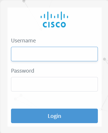
Figure 1. Log into Cisco Optical Network Controller
Screenshot of Log in Page

Create users in Cisco Optical Network Controller

Create a local user account in Cisco Optical Network Controller and define the user’s credentials, permissions, and status.

After the initial installation, use the administrator credentials established during setup to complete this task. Cisco Optical Network Controller provides these role levels.

Table 1. User access permisisons levels

Role

Permissions

Admin

No restrictions.

Supervisor

Similar to admin, but a supervisor user cannot perform user management and check logs.

Readonly

Can check data, but cannot provision resources.

Internal

Use this role during triage or troubleshooting to collect debug logs. We recommend using it only under the supervision of the Cisco Technical Assistance Center (TAC).

Before you begin

Before you begin:

  • Confirm the virtual IP used by Cisco Optical Network Controller.

  • Have the administrator username and password available.

Follow these steps to create users.

Procedure


Step 1

From the Cisco Optical Network Controller home page click Settings .

Step 2

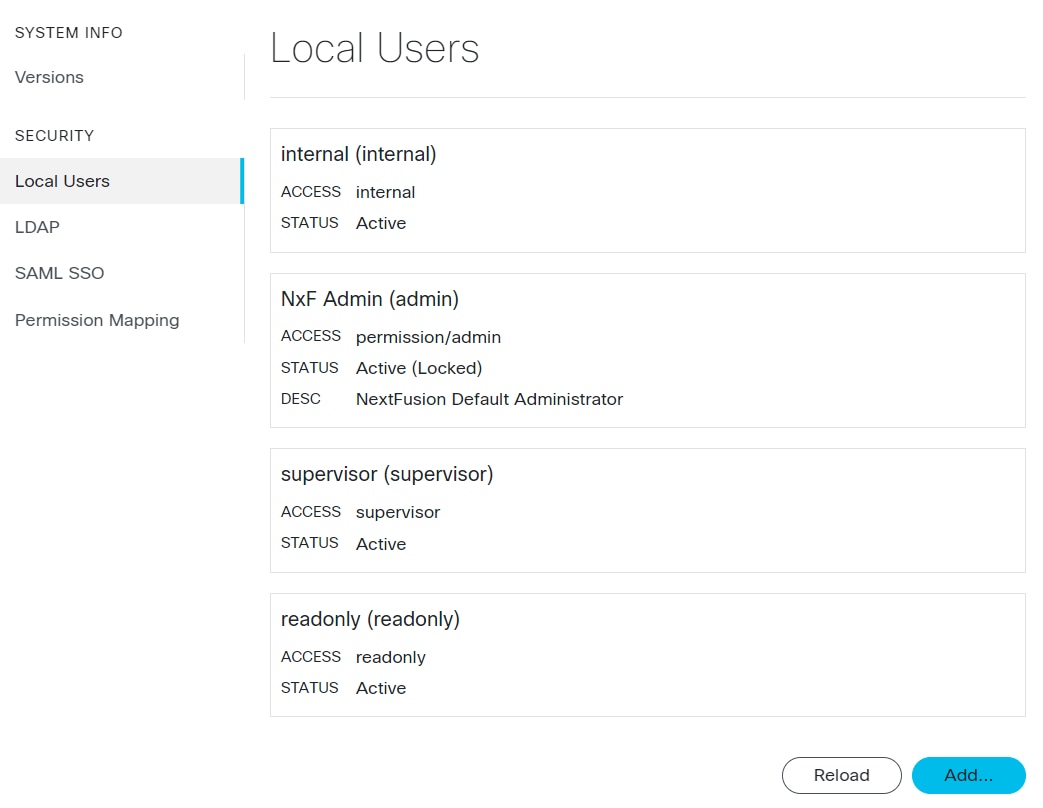
From the panel list, select Local Users and click Add .

Step 3

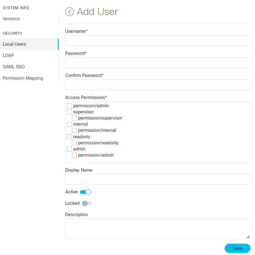
In the Add User screen, enter Username.

Step 4

Enter and confirm the password.

Step 5

Select the check box in the Access Permissions section to choose the access level for the user.

For more details about permisisons levels, see the Table 1 table.
Figure 2. Local Users
Screenshot of Local Users
Figure 3. Add User
Screenshot of Add User

Step 6

(Optional) Specify the Description and Display Name.

Step 7

Configure the user status by selecting the radio buttons. These radio buttons function independently, allowing both to be either enabled or disabled simultaneously.

Button

Action

Active

Enable or disable user login to Cisco Optical Network Controller.

Locked

Enable or disable user deletion.

When the lock is enabled, the user cannot be deleted. Disabling the lock allows the user to be deleted.

Step 8

Click Save.


Local users are created for ongoing Cisco Optical Network Controller operations.

Onboard Cisco Optical Site Manager nodes in Cisco Optical Network Controller

Onboarding Cisco Optical Site Manager nodes connects them to Cisco Optical Network Controller for discovery and provisioning. Only users with administrator or supervisor permissions can onboard nodes.

Before you begin

Log in to Cisco Optical Network Controller as an admin/supervisor user.

Follow any of these tasks to onboard Cisco Optical Site Manager nodes.

Procedure


Step 1

Onboard a single node using the Cisco Optical Network Controller interface.

For more details, see Add nodes on Cisco Optical Network Controller.

Step 2

Onboard multiple nodes using an Excel import.

For more details, see Import multiple nodes into Cisco Optical Network Controller.


Cisco Optical Site Manager nodes are onboarded and ready for discovery.

Add nodes on Cisco Optical Network Controller

Use this task to add a single Cisco Optical Site Manager node.

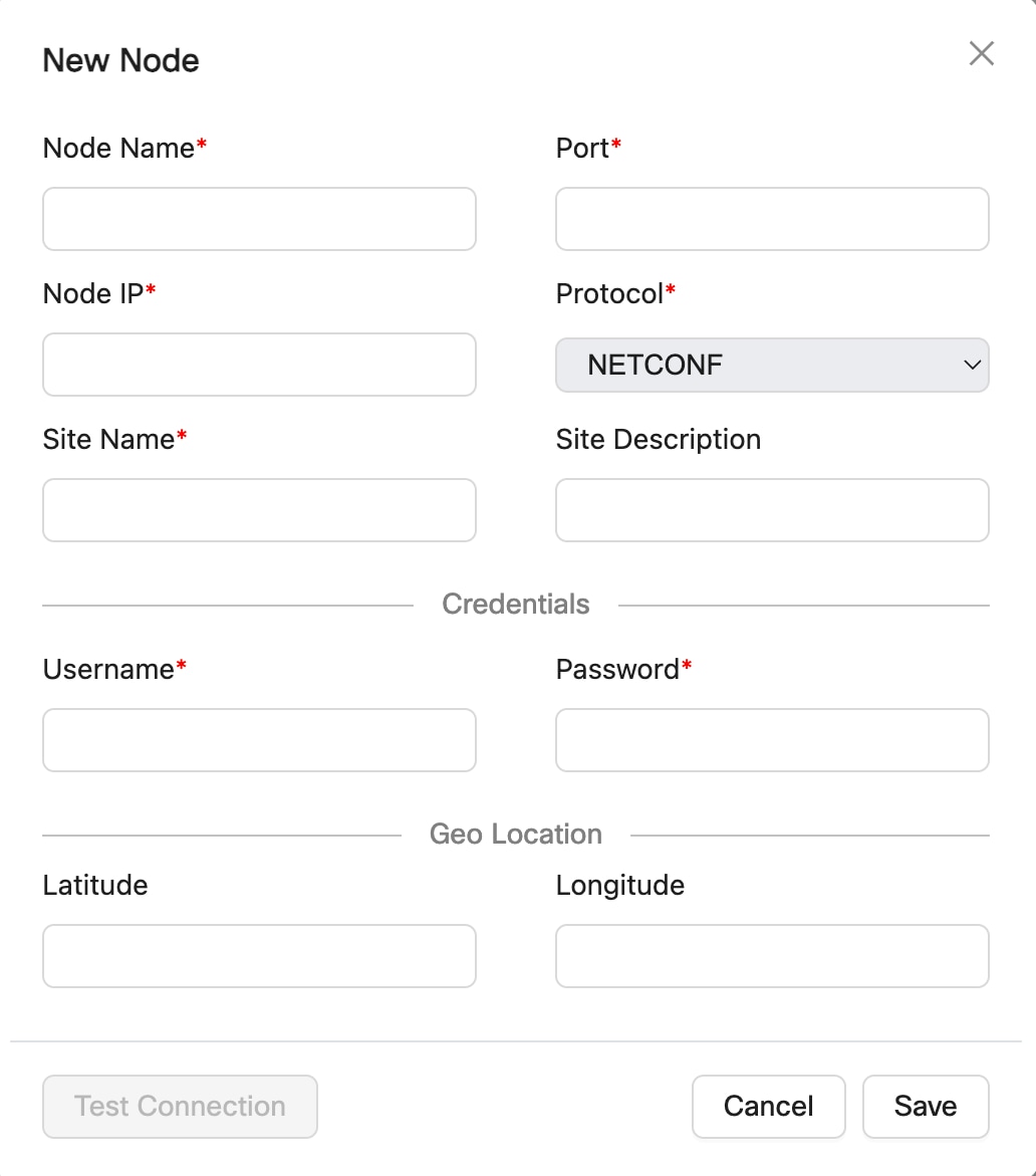
Figure 4. Add New Node
Before you begin

Verify these before addding to Cisco Optical Network Controller:

  • Verify the Cisco Optical Site Manager is reachable from Cisco Optical Network Controller server via DCN.

  • NETCONF port is enabled on the Cisco Optical Site Manager. For more details, see Enable NETCONF over SSH.

  • The COSM1K (NCS 1000 series) nodes must be added using port number 2022.

  • You must add only fully configured nodes. All passives and patchcords must already be created before you add a node.

Procedure

Step 1

Click Nodes in the left panel.

Step 2

Click New.

Step 3

In the New Node dialog box, enter the details necessary connect to the node.

Ensure that you enter valid a username and password of the node to enable Cisco Optical Network Controller to connect to the node. For details about field descriptions, see the Table 1 table.

Note


Use a Cisco Optical Site Manager administrator account to add and manage a Cisco Optical Site Manager node in Cisco Optical Network Controller. This account is required for onboarding and ongoing node operations, including performance monitoring collection, service provisioning and deletion, database backup and restore, and software download and activation. Other Cisco Optical Site Manager user roles are not supported for these operations.

Step 4

To test connectivity from Cisco Optical Network Controller to a Cisco Optical Site Manager node, perform these steps:

  1. (Optional) Click Test Connection to test the connectivity to the node.

    Note


    The Test Connection button is enabled only if the Node Name, Port and Node IP fields are filled.

    The Test Connection dialog opens for the selected node and shows the node name, node IP address, node port, connection status, and test duration..
  2. Click Try Again if you want to rerun the connection test.

  3. Click Ping if you want to verify node reachability from Cisco Optical Network Controller.

    The ping result shows the reachability status and test duration for the selected Cisco Optical Site Manager node.

Step 5

Click Save.

The new node is onboarded successfully and added to the Nodes table.

Cisco Optical Network Controller onboards the Cisco Optical Site Manager nodes.
Table 2. Add new node field descriptions

Field

Description

Mandatory

Node Name

Name of the new node you are adding.

Note


This name replaces the already configured Cisco Optical Site Manager node name.

Yes

Node IP

IP address of the new node which you are adding.

Note


Ensure that this IP does not overlap the Reserved internal IP addresses and subnets.

Yes

Port

The port number of the new node which you are adding.

Yes

Protocol

The protocol used for the new node which you are adding.

Yes

Site Name

The name of the site to which the new node belongs.

Yes

Username

The username for accessing the new node.

Yes

Note


Use an administrator account to add and manage a Cisco Optical Site Manager node in Cisco Optical Network Controller. This account is required for onboarding and ongoing node operations, including performance monitoring collection, service provisioning and deletion, database backup and restore, and software download and activation. Other Cisco Optical Site Manager user roles are not supported for these operations.

Password

The password for accessing the new node.

Yes

Site Description

The description of the site to which the new node belongs.

No

Latitude

The Latitude co-ordinate value that you want to assign for the new node to set its location on the map.

No

Longitude

The Longitude co-ordinate value that you want to assign for the new node to set its location on the map.

No

Import multiple nodes into Cisco Optical Network Controller

Use this task to import multiple nodes into Cisco Optical Network Controller by using a spreadsheet. The bulk import option enables you to add multiple nodes at the same time instead of adding them individually.

Cisco Optical Network Controller onboards nodes in batches:

  • XS profile: 2 nodes at a time

  • S and M profiles: 3 nodes at a time

Follow these steps to import multiple nodes from any spreadsheet into Cisco Optical Network Controller.

Procedure

Step 1

Click Nodes in the left panel.

Step 2

Click Import nodes to import the nodes in bulk.

Step 3

Click Dowload to download the node bulk import file template.

Step 4

For each node you want to import, enter its information in the appropriate columns in the dowloaded Excel sheet.

Step 5

In the Import xlsx dialog box, select the Excel sheet.

Figure 5. Import nodes
Screenshot of Import nodes
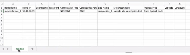
Screenshot of Bulk Import File

The sample bulk import template file includes these fields that you must fill out before importing the Excel sheet:

Table 3. Bulk Import File Template

Name

Description

Node Name

Name of the node Cisco Optical Site Manager node.

Note


This name replaces the already configured Cisco Optical Site Manager node name.

Node IP

The IP address of the node you are adding.

Note


Ensure that this IP does not overlap the Reserved internal IP addresses and subnets.

User Name

The username for accessing the new node.

Note


Use an administrator account to add and manage a Cisco Optical Site Manager node in Cisco Optical Network Controller. This account is required for onboarding and ongoing node operations, including performance monitoring collection, service provisioning and deletion, database backup and restore, and software download and activation. Other Cisco Optical Site Manager user roles are not supported for these operations.

Password

The password for accessing the new node.

Connectivity Type

The type of the protocol used for connecting the node.

Default: NETCONF

Connectivity Port

The port number of the node.

Port number 2022 for NCS 1000 series nodes.

Site Name

The name of the site to which the new node belongs.

Site Description

The description of the site to which the new node belongs.

Product Type

Set it as Cisco Optical Node.

Latitude

Specify the latitude co-ordinate value you want to assign to the new node to set its location on the map.

Longitude

Specify the longitude co-ordinate value you want to assign for the new node to set its location on the map.

After you upload the file, Cisco Optical Network Controller validates the entries and displays the message Import in progress while the nodes are being onboarded.


The new nodes are onboarded and added to the Nodes table. Wait until all nodes have completed onboarding.

What to do next

On the Nodes page, verify the total node count displayed at the top and match it with the number of nodes listed in the Excel file to ensure onboarding is complete.

Nodes

A node refers to a device in the network. You can add a single node or a set of nodes in the form of a batch at any given point in time.

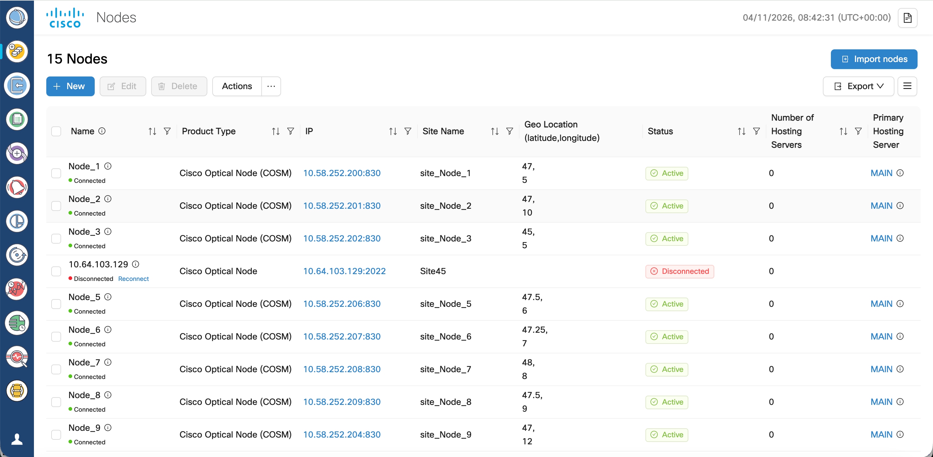
Use the Nodes screen to view the details of each node. The Nodes table displays the following details for each node:

  • Node Name: The name of the node. The node name provided by you must match the original node name used in Cisco Optical Site Manager. In case of any mismatch or discrepancy issues, user given name is configured on Cisco Optical Site Manager.

  • Product Type: The type of product the node belongs to. For example: Cisco Optical Site Manager.

  • IP: Port (NETCONF): The IP address of each node along with the port number.

  • Site Name: The location of the site that each node belongs to. For example: ROADM_Site_Bengaluru_33

  • Geo Location: The Geo location of each node in terms of the latitude and longitude values based on where exactly the node is situated in the world at any given time.

  • Status: The status of each node within the network to know whether it is active or disconnected.

  • Number of Hosting Servers: Define the number of SVO Line Cards present in the COSM NCS 2000 node.

  • Primary Hosting Server: Displays the active SVO line card hyperlink. Click the hyperlink to open the COSM admin plane for the hosting server.

  • Secondary Hosting Server: Displays the standby SVO line card hyperlink. Click the hyperlink to open the COSM admin plane for the hosting server.

  • Up Time: Displays the duration the COSM node is active.

  • Host Sync Error: Displays the sync error details.

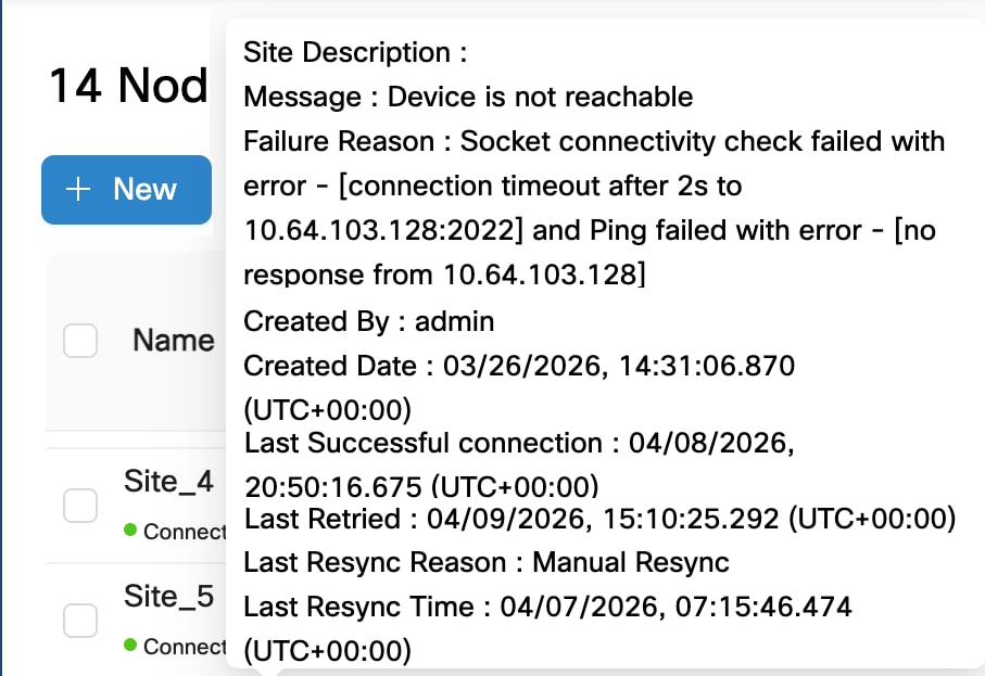
Hover over the information (i) icon that appears along with each node in this Node Name column to view these additional details of a node:

Figure 6. Additional details of a node
  • Site Description: A brief description of the site associated with the node.

  • Message: Displays information about any error conditions related to the node.

  • Failure Reason: Indicates why the node cannot connect or is unreachable. This field is only visible when a node is in Waiting_for_connection state.

    Here are example values for the field:

    • Socket connectivity check failed with error - [dial tcp 10.20.30.40:2020: connect: connection refused] but Ping succeeded

    • Socket connectivity check failed with error - [connection timeout after 2s to 10.20.30.40:22] and Ping failed with error - [no response from 10.20.30.40]

    • Socket connectivity check failed with error - [dial tcp 10.20.30.40:22: connect: no route to host] but Ping succeeded

  • Created by: Displays the user id that added the node.

  • Created Date: Shows the date and time when the node was added.

  • Modified Date: Shows the date and time when the node details were last updated.

  • Last Successful connection: Shows the date and time when the node last connected successfully.

  • Last Retried: Shows the date and time when the last connection attempt was made for this node. This field is only visible when a node is in Waiting_for_connection state.

  • Last Resync Reason: Shows the reason for the most recent resync of the node.

  • Last Resync Time: Shows the date and time when the most recent resync of the node occurred.

Figure 7. Nodes

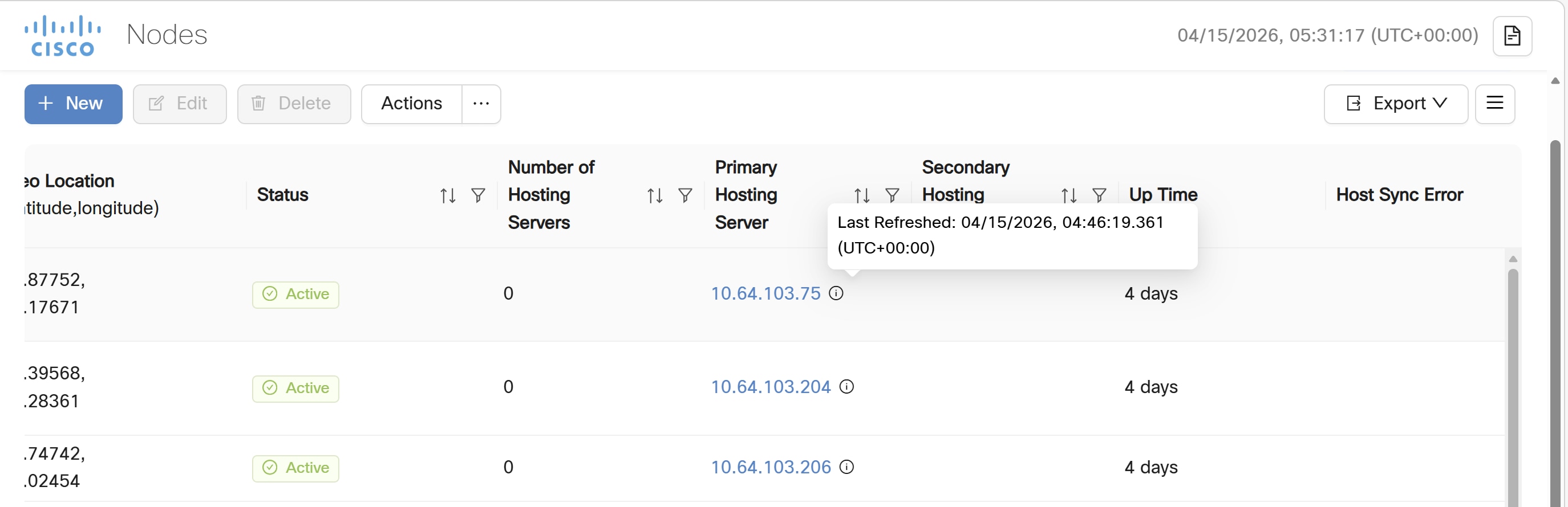
From release 26.1.1, the Nodes screen displays the last refreshed information for the primary hosting server. Hover over the i icon to get the latest refreshed information.

Figure 8. Last Refreshed information

Use the sort or filter options to sort and filter values in the table. You can also cross launch to Cisco Optical Site Manager using the links provided in this table.

Use the Actions button for synchronizing and configuring the network sync along with reconnecting the various nodes present in the network. These are the available options.

  • ReSync: Used for resyncing any selected node in the network.

  • ReSync All: Used for resyncing all the nodes in the network.

  • Reconnect: Used to reconnect any or all the nodes.

  • Configure Network Sync: Used for Daily Network Full Sync. Enable or Disable this functionality.

  • Test Connection: Used for sending pings to the far end node.

  • Resync Host Details: Used for resyncing NCS 2000 node with SVO line cards.


Note


  • Latitude and longitude values can be set in both Cisco Optical Site Manager and Cisco Optical Network Controller. The following scenarios are possible:

    • Geo location is set in both Cisco Optical Site Manager and Cisco Optical Network Controller: Cisco Optical Network Controller Geo location is used.

    • Geo location is set only in Cisco Optical Site Manager: Cisco Optical Site Manager Geo location is used .

    • Geo location is set only in Cisco Optical Network Controller: Cisco Optical Network Controller Geo location is used.

    • Geo location is not set in either Cisco Optical Network Controller or Cisco Optical Site Manager: You will be prompted to add the node in Topology with the edit button.

      For all the cases mentioned above, Cisco Optical Network Controller latitude and longitude value has a higher priority over the Cisco Optical Site Manager latitude and longitude values during the onboarding process. In case the Cisco Optical Network Controller latitude and longitude values are not provided, only then the Cisco Optical Site Manager latitude and longitude values are used.

  • Even if the user updates the Geo location in Cisco Optical Network Controller, it does not get updated in the Cisco Optical Site Manager device.

  • If the Geo location values that are coming from Cisco Optical Site Manager in a pre-filled format has more than four digits, then the length of the Geo location value is truncated to only four digits.

  • Node names are synchronized between Cisco Optical Network Controller and the nodes it manages. During onboarding, node name provided in Cisco Optical Network Controller is pushed to the node if the node has a different name. Changes made on Cisco Optical Site Manager is reverted as Cisco Optical Network Controller pushes the original name to Cisco Optical Site Manager.

    During a onboard and resync operation, Cisco Optical Network Controller pushes the current node name to the node, ensuring consistency even if changes were missed while the device was offline.


Validate node discovery and network topology in Cisco Optical Network Controller

Validation confirms that Cisco Optical Network Controller is ready for service provisioning on all the onboarded Cisco Optical Site Manager nodes.

Run this task after Cisco Optical Site Manager node onboarding is complete.

Follow these steps to validate Cisco Optical Site Manager node discovery and network topology.

Procedure


Step 1

Verify that the connectivity status for each onboarded Cisco Optical Site Manager node under the Node Name column is displayed as Connected.

Step 2

Verify that the Status for the node Name is displayed as Active.

Wait at least 60 seconds after discovery completes before sending TAPI requests.

Step 3

Select Topology in the left panel to display nodes and links on the map.

For details about topology review, see Topology in Cisco Optical Network Controller Configuration Guide.

Step 4

Verify that all the expected nodes and connections appear in the Topology page.

The topology view reflects the onboarded network.

Step 5

Click Inventory in the left panel to verify the detailed inventory for the site.

For details about inventory review, see Network Inventory in Cisco Optical Network Controller Configuration Guide.

Cisco Optical Network Controller displays all inventory items for the selected site. Click a node to view its details.


Node discovery, network topology, and network inventory views are validated and ready for circuit provisioning.

Circuits

The Service Manager application in Cisco Optical Network Controller provides centralized management of network services, particularly circuits. Use Service Manager to visualize, provision, monitor, edit, and delete circuits.

Supported circuit types

Cisco Optical Network Controller supports these DWDM circuit types in both GMPLS and CPCE control planes:

  • OCH-NC: Establishes connectivity between two optical nodes on a specified wavelength. The connection uses ports on multiplexer/demultiplexer and add/drop cards.

  • OCH-CC: Extends the OCH-NC to create an optical connection from the source client port to the destination client port of the TXP/MXP cards. An OCH-CC circuit represents the end-to-end client service through the DWDM system.

  • OCH-Trail: Transports OCH-CC circuits over the common trunk-to-trunk connection between transponder (TXP) or muxponder (MXP) line cards. When you create an OCH-CC between two TXP or MXP cards, Cisco Optical Network Controller automatically creates the corresponding OCH-Trail.

Provisioning behavior

A circuit represents an end-to-end connection and consists of an alternating series of cross-connections and link connections. The provisioning scope depends on the control plane:

  • For CPCE circuits, Cisco Optical Network Controller makes configuration changes across multiple participating nodes.

  • For GMPLS circuits, Cisco Optical Network Controller sends the circuit provisioning request only to the head node.

The Provisioning Wizard collects the required circuit information in a step-by-step workflow and generates the required configuration for the participating nodes. On the final page, review the inputs, update service parameters if required, and deploy the configuration.

Deployment and validation

Cisco Optical Network Controller deploys configuration changes as an atomic transaction. It makes a best effort to complete all operations together or none of them. If configuration fails on any device during a multi-node operation, rollback restores the participating nodes to their state before provisioning was attempted.

After provisioning is complete, the circuit appears in the Service List table. The lifecycle state initially appears as PLANNED and changes to INSTALLED after the circuit is installed. Monitor provisioned circuits by using the Circuit Monitoring Workspace. For details, see Provision CPCE services.

Cisco Optical Network Controller alarms

Cisco Optical Network Controller alarms help monitor network conditions and support troubleshooting across managed nodes, circuits, and network resources. The Alarms application provides active and historical alarm information, including severity, affected object, service impact, acknowledgement status, user notes, and correlation details. You can use alarm information to:

You can use alarm information to:

  • Review current and previous faults.

  • Identify root-cause conditions through network-level alarm correlation.

  • Forward selected alarms or events to external SNMP managers.

For more information, see Alarms and Alarms troubleshooting.

Cisco Optical Network Controller workspaces

Workspaces combine information from multiple Cisco Optical Network Controller applications into a single view. They help users review related topology, alarm, service, link, and performance information without switching between separate applications.

The available workspaces support these monitoring and management views:

Workspace Focus
Network Monitoring Workspace Provides a network-level view of node status, alarms, links, and performance metrics. Alarm details are displayed based on the node or link selected in the topology.
Circuit Monitoring Workspace Provides a circuit-level view of the service path, associated alarms, restoration events, and performance history.
Link Monitoring Workspace Provides a link-level view that integrates the links table, topology, alarms, PM history, and associated circuits. Selecting a link in the links list highlights it in topology, and selecting nodes or links in topology filters the links list.

Workspace panels are interactive and can include Alarms, Service List, Topology, Detailed Service Path, Links, and PM History views. Layout changes can be saved or reset, and contextual actions can cross-launch to related node, equipment, port, circuit, or link information.

For more information, see Workspaces.

Cisco Optical Network Controller PM history

The PM History application helps you view and generate performance monitoring reports for interfaces that are part of onboarded nodes. It is available in the Network Monitoring workspace for links and in the Service Monitoring workspace for circuits through the detailed service path.

PM History provides these capabilities:

  • Collects PM data from onboarded Cisco Optical Site Manager nodes at 15-minute and 24-hour intervals.

  • Displays PM data in tabular and graphical formats based on the selected node, interval, date and time range, interface type, port, and location.

  • Generates historical PM reports for Cisco Optical Network Controller entities such as circuits or services, links, and ports.

  • Retrieves older PM data from archived storage when the selected data is outside the active retention period.

For more information, see PM History.

Common failures and troubleshooting procedures for Cisco Optical Network Controller

This section lists common errors and their troubleshooting or workaround steps. If the issues persist after trying the suggested workarounds, contact Cisco TAC and collect a tech dump as described.

This section covers these Cisco Optical Network Controller troubleshooting areas:

  • Installation failures

  • Node addition, deletion, and resync operation failures

  • Topology failures

  • Circuit creation and deletion failures

  • Alien import and PM failures

If the issues are still not resolved by the suggested workarounds contact Cisco TAC after collecting tech dump.

Figure 9.

Installation failure

This table lists common installation failures and provides troubleshooting steps for each issue.

Table 4. Installation Failure

Reason

Description/Details

Troubleshooting

Workaround/Remarks

CONC UI Login Failures

Unable to login to CONC UI after installation

Check if admin password was created part of installation.

Also check if the password is specified correctly.

If admin password was not created during installation, create it and try login again

VM Login Failures

Unable to SSH to VM – It will continue to ask for password

This can happen when keys are not matched or ed25519 is not used for key generation

For accessing SSH, ed25519 key is required. The ed25519 key is different from the RSA key. So, follow the steps in installation documents for SSH Key Generation.

Ensure the public key specified during installation is matching with the private key used for login.

SSH connection time out

This can happen if both northbound and eastbound are in same network

Keep northbound and eastbound in separate network

ONC pods not coming up as ready

Some ONC pods are in Init:ContainerStatusUnknown and few others in ImagePullBackOff status when running

kubectl get pods –A command

Data Volume Size (GB) not mentioned correctly as per the VM Profile(XS, S, M) during installation

[OR] No Disk Space (/data) available when running “df -h” command

Reinstall ONC - Configure data volume according to the VM profile during installation

VM time is not in sync with NTP time

Validate if timezone is synced with NTP and the time is up to date post bring up boot up.

You can do this by using the command “timedatectl status”

It should show:

System clock synchronized: yes

NTP service: active

Check if NTP is configured correctly and VM time is in sync with it

Make sure the hardware clock ( ESXi Host ) is not far off the system time on all the nodes.

DNS not configured properly or DNS server not reachable

Check if DNS server was mentioned correctly during installation and the mentions DNS servers are reachable

Configure DNS server properly during installation.

Node addition failure

The table outlines node addition failures and the steps to resolve them.

Table 5. Node Addition Failure

Reason

Description/Details

Troubleshooting

Workarounds/Remarks

Connection Failure

UI status – Disconnected

Check connectivity to the Node by –

Check if the user provided details like Connectivity type, IP, Port, and node credentials are correctly mentioned in Cisco Optical Network Controller UI.

Correct the details provided in the Cisco Optical Network Controller UI.

Check if Ping to the node is working

Check if the node is properly configured and has proper network configuration.

Check if the Netconf connectivity to the node on the Netconf port is working.

Check if the Netconf and XR configuration is proper on the node

Collection Failure

UI status – Failed/Errored

Check the release on the NCS1010/COSM node.

COSM / NCS1010 should be running Supported Release versions.

If the issue occurs even when the required software versions are present call TAC.

Node deletion failure

Use this table to identify node deletion failures and find troubleshooting guidance.

Table 6. Node Deletion Failure

Reason

Description/Details

Troubleshooting

Workarounds/Remarks

Node is part of a Circuit

UI status – Circuit/Service spanning over the node

This is expected Cisco Optical Network Controller behavior.

Delete the Circuit/Connectivity-service (via NBI) and then try Node deletion.

Collection In Progress

UI Status – Node cannot be deleted because Collection is in Progress

This is expected Cisco Optical Network Controller behavior.

Wait for the collection to be completed and then try node deletion.

Resync in Progress

UI status – Node cannot be deleted because Collection is in Progress

This is expected Cisco Optical Network Controller behavior.

Wait for the Resync to be completed and then try node deletion.

Connectivity Check in Progress

UI status – Node cannot be deleted because Waiting for Connection

This is expected Cisco Optical Network Controller behavior.

Wait for the Resync/Recollection to be completed and then try node deletion.

Resync operation failure

This table lists common resync operation failures and provides troubleshooting steps for each issue.

Table 7. Resync Operation failure

Reason

Description/Details

Troubleshooting

Workaround/Remarks

Node not reachable

UI status –

Node – Disconnected

Status – Blank/Resync pending/Resync Failed

This is expected Cisco Optical Network Controller behavior.

Check if the node is properly configured and has proper network configuration.

Check if the Netconf and XR configuration is proper on the COSM/NCS1010 node.

Try Resync again

Check the release on the SVO/NCS1010 node for compatibility with Cisco Optical Network Controller release.

Node credentials changed on the node

UI status –

Node – Disconnected

Status –Blank/Resync pending/Resync Failed

This is expected Cisco Optical Network Controller behavior.

Edit the node credentials via Optical Network Controller UI and click OK. Resync will happen automatically.

Topology failure

The table outlines topology failures and the steps to resolve them.

Table 8. Topology Failure

Reason

Description/Details

Troubleshooting

Workaround/Remarks

Lat and Long not mentioned for nodes in Import Excel/Add Node UI Dialog

Some of the nodes in Node table are not displayed in Topology

This is expected Cisco Optical Network Controller behavior.

When user enters topology, ONC will display “There are a few nodes without geographical coordinates. Please click on the pen icon to assign them manually.” User need to click Pen icon and drag the nodes to required location. Alternately the latitude and longitude can be edited in Nodes Page. Click Nodes in the left panel. Click EDIT after selecting the node from the table.

Links do not show up in ONC

Some of the links which are up in network might not show up in ONC topology view

Check if neighbours are shown correctly in COSM Web UI – Node Functional View and Neighbors are shown correctly in Optical Setup -> Optical Configuration

Correct COSM errors if any.

Circuit creation failure

Use this table to identify circuit creation failures and find troubleshooting guidance.

Table 9. Circuit Creation Failure

Reason

Description/Details

Troubleshooting

Workaround/Remarks

No Route Available

Cisco Optical Network Controller UI status – NA

No route can be found by the Path Computation Engine. Could be expected behavior.

Check the topology and the route for the currently created services.

Wrong SIP Selection

Cisco Optical Network Controller status – NA

SIP UUIDs are not proper

Check the list of available SIPs and supply only SIPs returned from the T-API topology-context fetched by the Hierarchical Controller from Optical Network Controller as part of the get call.

Node(s) not reachable

Cisco Optical Network Controller status – NA

Circuit will move to Pending-Removal lifecycle state.

Check the node reachability and fix it

Delete the connectivity-service

Recreate the connectivity-service.

Routing constraint is Invalid

Cisco Optical Network Controller status – NA

Could be due to invalid UUIDs provided in the connectivity-service request constraints.

Check the list of available constraints and supply only valid constraints.

Routing Constraint Not Feasible

Cisco Optical Network Controller status – NA

Could be expected behavior since a route may not be available meeting the Constraint provided.

Check the topology and the constraint provided.

Circuit deletion failure

This table lists common circuit deletion failures and provides troubleshooting steps for each issue.

Table 10. Circuit Deletion Failure

Reason

Description/Details

Troubleshooting

Workaround/Remarks

Circuit Deletion attempted before circuit creation is completed

Connectivity-service lifecycle-state is Planned and same service deletion is attempted.

This is expected behavior.

Wait till the circuit lifecycle-state is either Installed or Pending-removal.

Invalid Circuit ID

Invalid connectivity-service UUID is provided

This is expected behavior.

Connectivity-service should be of an existing connectivity-service in the T-API connectivity-context.

Alien import failure

The table outlines alien import failures and the steps to resolve them.

Table 11. Alien import failure

Reason

Description/Details

Troubleshooting

Workaround/Remarks

Alien file format is not proper

UI status – Request Failed

This is expected Cisco Optical Network Controller behavior.

Please check the file format. Cisco Optical Network Controller supports XML file format from Cisco Optical Network Planner only.

PM failure

Use this table to identify PM failures and find troubleshooting guidance.

Table 12. PM failure

Reason

Description/Details

Troubleshooting

Workaround/Remarks

Node Reachability

Cisco Optical Network Controller UI status –

Node Status – Disconnected

This is expected Cisco Optical Network Controller behavior if the node is not reachable or the interface is not UP/Working on the node.

Check the node connectivity to the COSM node using Ping.

Node is onboarded recently

PM data is not shown for the node

This is expected Cisco Optical Network Controller behaviour – After the node is onboarded, it could take more than 15 min to show up 15 min PM data and 24 hours to show up 24 Hr PM data

Wait for the minimum duration (15 min or 24 Hr) for PM collection to start from ONC and show up in GUI

Cisco Optical Network Controller logs

Logs help you track user and system activity, export audit information, review developer logs, schedule archived log collection, and collect diagnostic data for support.

The Logs application organizes log data into tabs so that operators can find, filter, export, and archive log information from a single location. The log enhancements provide organized log management, filtering, pagination, export options, retention and archiving, and access control for different user roles.

  • Audit: Displays audit log entries with fields such as time, category, identifier, username, client IP, and message. Audit categories include system, node, inventory, topology, service, alarm, alien import, and site audit events.

  • Debug: Displays developer logs with filter options such as namespace, microservice, container, log level, time range, and search.

  • Archives: Provides access to archived audit logs and debug logs. Archived logs can be scheduled, downloaded, deleted, suspended, resumed, or modified based on operational requirements.

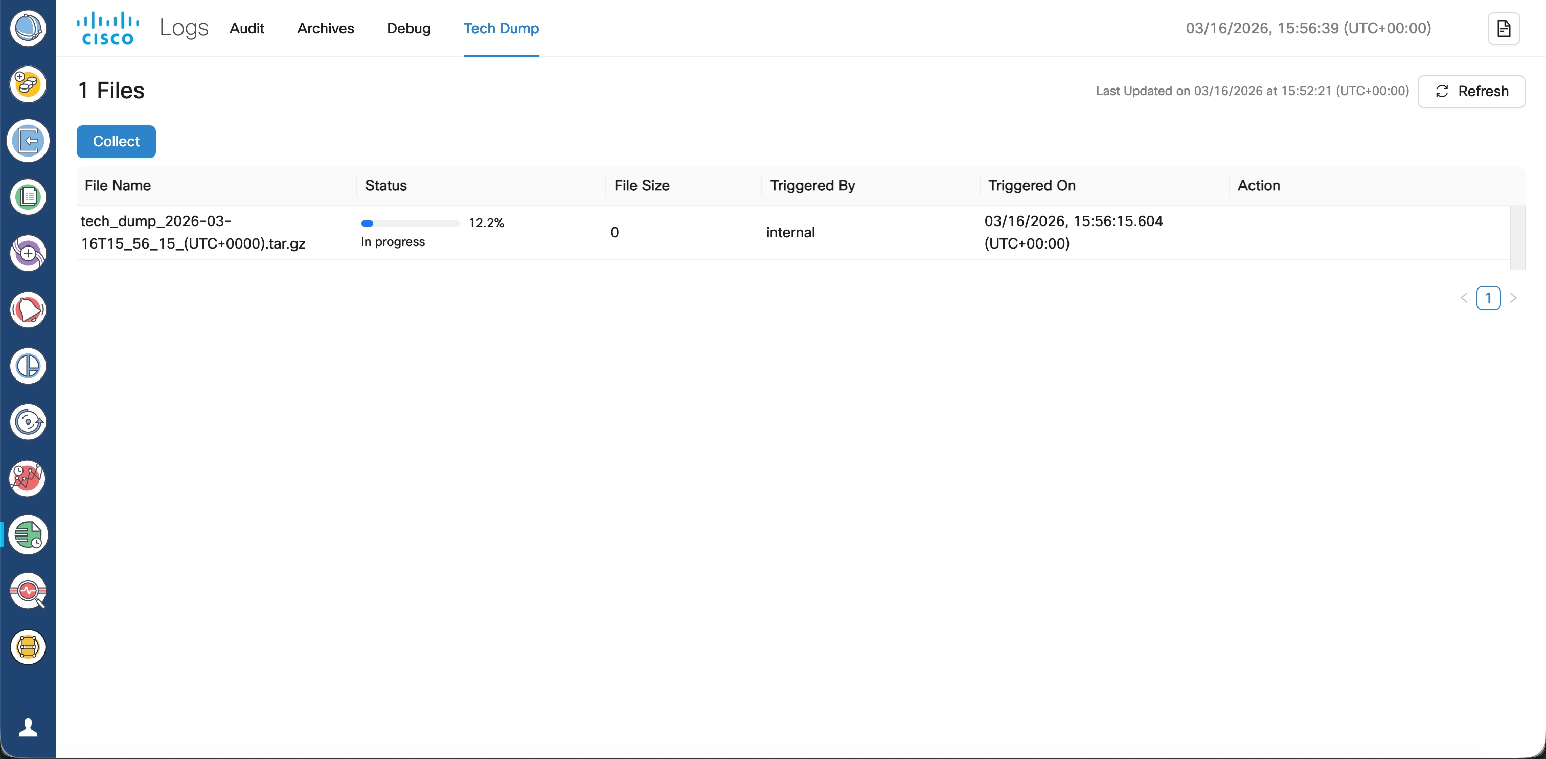
  • Tech Dump: Collects diagnostic data bundles that include system information, logs, configuration files, and operational data for troubleshooting.

For more information, see Logs.

Generate and download tech dump logs

Tech dump logs on Cisco Optical Network Controller are diagnostic data bundles. They collect detailed system information, logs, and state files to help with troubleshooting and support.

From R26.1.1, you can collect, download, and delete tech dump logs from the Tech Dump tab of Logs.

When you generate a tech dump, Cisco Optical Network Controller compiles logs, configuration files, and operational data into a single archive file.

Before you begin

Ensure that there is sufficient space on the VM hosting the Cisco Optical Network Controller.

Follow these steps to generate and download the tech dump logs:

Procedure

Step 1

Click Logs.

Step 2

Click Tech Dump tab.

For details about the field descriptions on this tab, see Table 1.

Step 3

Click the Collect button to initiate the log collection.

A confirmation message appears, stating that starting a new log collection will delete the existing log file.

Step 4

Click the Collect the DB dump check box if you also want to collect information about CONC databases.

Note


Selecting this check box does not collect any sensitive information, including device credentials.

Step 5

Click Collect on the dialog box.

Collected log files remain local to the current active VM. If a switchover occurs, these files are not available on the new active VM.

Wait for the log collection to finish.

Step 6

Click Download to download the logs or Delete to remove them.

Warning


Do not log out during the download, as it can cause the file download to fail.


A file named in the tech_dump_<timestamp>.tar.gz format is downloaded.

The Tech Dump tab displays these fields:

Table 13. Tech dump tab field descriptions

Field

Description

File Name

Displays the name of the generated tech-dump file, including timestamp and timezone.

Status

Shows the current state of the tech-dump file generation. A green check mark indicates successful completion.

File Size

Indicates the size of the generated tech-dump archive in MB.

Triggered By

Shows the user ID that triggered the tech-dump collection.

Triggered On

Shows the exact timestamp (date and time with timezone) when the tech-dump creation started.

Action

Provides available operations for the generated file:

  • Download: Download the collected logs.

  • Delete: Delete the collected logs.

Note


These options are not displayed when the log collection is in progress.

Outcome

After completing this chapter, Cisco Optical Network Controller is installed, configured, and ready for network operations.

Cisco Optical Site Manager nodes are onboarded, optical circuits are provisioned, and operational workflows such as monitoring, alarms, PM history, and troubleshooting are available for ongoing management.