Traffic Management with VOQs

Traffic management with VOQs

A traffic management model with Virtual Output Queue (VOQ) is a QoS queuing architecture that

  • enables per-egress interface queuing at ingress using VOQs

  • prevents head-of-line (HOL) blocking by isolating traffic destined for different egress interfaces, and

  • provides granular control over network traffic congestion and bandwidth allocation for data packets.

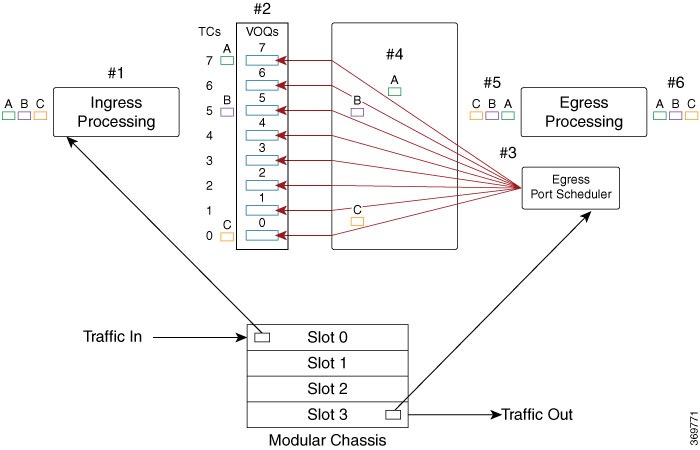
VOQs—VOQs are buffers at the ingress that holds traffic for a specific egress port, ensuring traffic is queued only when the destination is ready to receive. Your routers support up to eight output queues per main interface or physical port. For every egress output queue, the VOQ model earmarks buffer space on every ingress pipeline. This buffer space is in the form of dedicated VOQs. These queues are called virtual because the queues physically exist on the ingress interface only when the line card actually has packets enqueued to it.

Head-of-line blocking—In traditional ingress queuing systems, traffic destined for multiple egress ports may be held in a single shared queue. If the egress port for the first packet is congested, all subsequent packets—even those destined for other non-congested ports—are blocked from forwarding. This effect is referred to as head-of-line blocking and results in reduced traffic throughput and increased latency.

Key features of VOQ-based traffic management

These are the key features of the VOQ-based traffic management model:

  • Per-egress Queuing at Ingress: Virtual Output Queues are created per traffic class and per egress interface, allowing granular traffic isolation and precise scheduling.

  • Eight VOQs per Egress Port: For each egress interface, eight VOQs—corresponding to eight traffic classes—are reserved across all ingress interfaces, ensuring efficient prioritization of data packets.

    For more information on the various types of traffic classes and packet classification, see Classify Packets to Identify Specific Traffic.

  • Head-of-line Blocking Prevention: By dedicating VOQs for each destination, the model eliminates congestion caused by blocked packets for other egress ports.

  • Dynamic VOQ Instantiation: VOQs are created only when packets are present, optimizing buffer usage across ingress pipelines.

  • Connector Mesh: A logical mesh of connectors enables integrated handling of credit requests, grant responses, and data transmission between ingress and egress.

  • Credit-Based Scheduling: Egress ports issue credits to ingress VOQs based on availability, ensuring bandwidth is distributed according to QoS priorities.

  • Throughput Optimization and Loss Reduction: The architecture minimizes packet drops during congestion and maximizes throughput by forwarding only when the egress is ready.

Benefits of VOQ model

The VOQ-based traffic management model improves traffic handling efficiency and network performance by introducing a queuing architecture that

  • reduces head-of-line blocking by separating queues per egress destination,

  • minimizes packet drops by queuing only when egress resources are available, and

  • supports lossless packet forwarding for high-priority traffic under congestion scenarios.

Table 1. Differences between non-VOQ-based traffic management and VOQ-based traffic management

Non-VOQ-based traffic management

VOQ-based traffic management

Ingress queues traffic without visibility into egress port availability.

Ingress buffers traffic per egress port using dedicated VOQs.

Prone to congestion due to head-of-line blocking.

Prevents head-of-line blocking by isolating queues per destination.

Inefficient use of bandwidth when packets are dropped mid-pipeline at ingress due to congestion at the egress.

Minimizes wastage of router resources by dropping traffic packets only at ingress when egress is unavailable.

Limitations of VOQ model

Before you install the QoS features on your router, consider these limitations that could impact scalability, system memory usage, and system behavior under high-load conditions:

  • Replication overhead: Each egress queue must be replicated as an ingress VOQ on every slice of every NPU or ASIC. This increases memory usage significantly.

  • Reduced scalability: The total egress queue scale is lower due to the replication requirement, limiting system-wide queueing flexibility.

  • Resource consumption: As the number of egress ports or linecards increases, the system must replicate VOQs across all ingress NPUs, consuming significant buffer and memory resources.

    For example, adding a new NPU with 20 interfaces may require 160 additional VOQs on every existing NPU (20 interfaces × 8 traffic classes per interface).

  • On-chip buffer usage: In high-scale scenarios with 1000+ active VoQs, on-chip buffer (OCB) may be exhausted, causing unexpected traffic drops even when traffic rates are within shaping thresholds.

How traffic management with VOQs work

Summary

The key components involved in VOQ-based traffic management are:

  • Ingress Interface: Classifies, marks, and polices incoming data packets. The ingress interface is always mapped to a physical port.

  • Ingress VOQ: Buffers packets based on egress port and traffic class; instantiated dynamically when traffic is present. Every ingress interface port maintains eight VOQs—one for each traffic class—dedicated to a specific egress port.

  • Connectors: Logical links between ingress NPUs and egress ports that handle credit requests, grant responses, and data transmission across the fabric cards.

  • Egress Scheduler: Allocates credits based on available bandwidth and priority policies.

  • Egress Interface: Applies final markings and transmits packets to the next hop. The egress interface is always mapped to a physical port.

Traffic management with VOQs involves a coordinated sequence of queuing and scheduling actions between ingress and egress components to ensure efficient and lossless packet forwarding. The key components—ingress interface, Virtual Output Queues (VOQs), connector mesh, egress scheduler, and egress interface—work together to classify incoming traffic, buffer it per egress destination, allocate transmission credits based on availability, and transmit packets across the switch fabric with minimal latency and packet loss.

Workflow

Figure 1. Traffic flow from ingress port on slot 0 to egress port on slot 3

Theses stages describe how traffic management with VOQs work.

  1. The ingress interface classifies and marks incoming packets.

    The router receives packets—A (green), B (pink), and C (brown)—on the ingress interface. This is where packet marking, classification, and policing are applied based on QoS policies.


    Note


    This diagram illustrates a modular chassis with multiple slots (Slot 0 to Slot 3).


  2. The ingress interface maps packets to dedicated VOQs.

    Per traffic-class, each packet is enqueued into a VOQ corresponding to its egress port. For example, in the figure:

    • Packet A (green) is mapped to TC7,

    • Packet B (pink) is mapped to TC5, and

    • Packet C (brown) is mapped to TC0.

    This one-to-one VOQ mapping ensures proper congestion management and accurate scheduling for each flow.

  3. The egress scheduler allocates transmission credits.

    Based on the availability of egress bandwidth, the egress port scheduler issues credits that determine the sequence and rate of packet transmission towards the egress interface.

  4. The fabric switch forwards eligible packets to the egress port.

    Once credits are received, the eligible packets are transmitted across the fabric card toward the appropriate egress port.

  5. The egress interface marks and prepares packets for forwarding.

    At the egress interface, any final packet markings or required shaping is enforced before forwarding to the next hop.

  6. The router transmits packets to their outbound destination.

    At this stage, congestion is managed in such a way that no packets are dropped, and all packets are transmitted to the next hop.