Congestion Management

Traffic congestion management

Congestion management is a QoS traffic-management model that

  • defines how traffic is organized into queues when congestion occurs on an interface

  • defines how classified packets are mapped to those queues, and

  • defines how queues are scheduled for transmission based on priority or policy rules.

Key features for congestion management

  • Low Latency Queueing with Strict Priority Queueing: Ensures time-sensitive traffic (such as voice or real-time video) is placed in a strict-priority queue so it is serviced first, minimizing latency and jitter while other traffic is still managed fairly.

  • Traffic Shaping: Smooths traffic bursts by buffering and pacing packets so that the egress rate matches downstream link speeds or contracted rates, helping prevent congestion caused by data-rate mismatches.

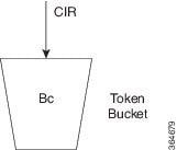
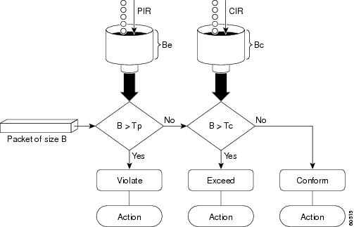
  • Traffic Policing: Enforces a maximum traffic rate on an interface using token-bucket algorithms and drops (or marks) packets that exceed the configured rate, helping protect bandwidth and maintain service quality across classes of traffic.

The table lists the key differences among Low Latency Queuing (with Strict Priority), Traffic Shaping, and Traffic Policing to help you understand how each feature manages traffic under congestion.

Table 1. Key differences among low latency queuing (with strict priority), traffic shaping, and traffic policing
Aspect LLQ with strict priority queuing Traffic shaping Traffic policing
Primary goal Prioritize time-sensitive traffic to minimize latency and jitter. Match traffic output rate to downstream speed or contracted profile. Enforce a maximum allowed traffic rate using token-bucket metering.
Behavior with excess traffic Strict priority can cause lower-priority queues to not get serviced if priority traffic is heavy. Buffers excess packets and sends them later. It smooths bursts. Does not buffer. Packets that exceed rate may be marked or dropped.
Traffic direction Egress Egress only (explicit). Ingress (egress policing is not supported).
Impact on other traffic May starve lower-priority queues unless an optional shaper is used. Prevents downstream bottlenecks by smoothing bursts; does not drop traffic by design. Can drop packets based on exceed/violate actions; partitions traffic into service classes.
Handling of traffic bursts Priority traffic bypasses others; does not inherently smooth bursts or buffer. Buffers bursts and releases later to match rate profile. Bursts may trigger exceed/violate events; uses burst parameters.

Low-latency queuing with strict priority queuing

Low-latency queuing with strict priority queuing is a QoS congestion management feature that

  • integrates strict priority queuing into the Class-Based Weighted Fair Queuing (CBWFQ) model

  • ensures delay-sensitive traffic is always dequeued ahead of other traffic classes, and

  • minimizes latency and jitter for critical applications such as voice and real-time video.

CBWFQ is a QoS scheduling model that assigns bandwidth to traffic classes based on configured weights and ensures each class receives its allocated portion of service during congestion.

Priority Queuing is a scheduling method that dequeues packets from the highest-priority queue before any other queue, allowing delay-sensitive traffic to pre-empt lower-priority classes; in strict priority mode, lower-priority queues may not be serviced if high-priority traffic is continuously present.

Table 2. Feature History Table

Feature Name

Release Information

Feature Description

Priority Propagation on Egress Queues

Release 25.3.1

Introduced in this release on: Centralized Systems (8400 [ASIC: K100])(select variants only*)

* This feature is now supported on Cisco 8404-SYS-D routers.

Priority Propagation on Egress Queues

Release 25.1.1

Introduced in this release on: Fixed Systems (8700 [ASIC: K100], 8010 [ASIC: A100])(select variants only*)

This feature is supported on:

  • 8712-MOD-M

  • 8011-4G24Y4H-I

Low Latency Queueing with Strict Priority Queueing

Release 25.1.1

Introduced in this release on: Fixed Systems (8010 [ASIC: A100])(select variants only*)

*This feature is supported on Cisco 8011-4G24Y4H-I routers.

Low Latency Queueing with Strict Priority Queueing

Release 24.4.1

Introduced in this release on: Fixed Systems (8700) (select variants only*)

This feature ensures that time-sensitive traffic receives dedicated priority, ensuring minimal latency and jitter while congestion for other types of traffic is managed fairly, guaranteeing high performance for critical applications and efficient overall traffic management.

*This functionality is now supported on Cisco 8712-MOD-M routers.

Priority Propagation on Egress Queues

Release 24.3.1

Introduced in this release on: Fixed Systems (8200 [ASIC: P100], 8700 [ASIC: P100])(select variants only*); Modular Systems (8800 [LC ASIC: P100])(select variants only*)

You can now ensure that high-priority traffic is consistently prioritized across multiple sub-interfaces on the same network port, enhancing the performance of critical applications.

This is achieved by enabling support for egress queuing policy maps that allow high-priority P1 traffic (on class TC7) to take precedence over non-P1 traffic across sub-interfaces. This feature ensures that critical traffic, such as voice or real-time video, is always given the highest priority, regardless of the sub-interface it is associated with, thereby maintaining optimal network performance and reducing latency for essential services.

*This feature is supported on:

  • 8212-48FH-M

  • 8711-32FH-M

  • 88-LC1-36EH

  • 88-LC1-12TH24FH-E

  • 88-LC1-52Y8H-EM

Low Latency Queueing with Strict Priority Queueing

Release 24.3.1

Introduced in this release on: Modular Systems (8800 [LC ASIC: P100]) (select variants only*), Fixed Systems (8200) (select variants only*), Fixed Systems (8700 (P100, K100)) (select variants only*)

This feature ensures that time-sensitive traffic receives dedicated priority, ensuring minimal latency and jitter while congestion for other types of traffic is managed fairly, guaranteeing high performance for critical applications and efficient overall traffic management.

*This feature is supported on:

  • 88-LC1-12TH24FH-E

  • 88-LC1-52Y8H-EM

  • 8212-48FH-M

  • 8711-32FH-M

Low Latency Queueing with Strict Priority Queueing

Release 24.2.11

Introduced in this release on: Modular Systems (8800 [LC ASIC: P100])(select variants only*)

With this feature, time-sensitive traffic receives dedicated priority, ensuring minimal latency and jitter while congestion for other types of traffic is managed fairly, guaranteeing high performance for critical applications and efficient overall traffic management.

You can also configure low latency queueing with strict priority queueing at the subinterface level, ensuring that the strict priority policy applies only to traffic on that specific subinterface, not the entire physical interface. This configuration is useful in scenarios where multiple services share the same physical link but have different QoS requirements.

*This feature is supported on 88-LC1-36EH.

Guidelines for configuring low-latency queuing with strict priority queuing

Priority and scheduling behavior

  • Only priority levels 1 to 7 are supported, where 1 is the highest and 7 is the lowest priority; the default CoSQ 0 has the lowest priority among all classes.

  • Egress policing is not supported, and in strict priority mode, heavy priority traffic can prevent lower-priority queues from being serviced.

  • The platform enforces a strict class hierarchy, where higher traffic classes take precedence over lower ones. This hierarchy can be redefined through an egress queuing policy map when configuring LLQ with strict priority.

  • When operating in strict-priority mode, egress scheduling follows the default class order TC7 >TC6 > TC5 > TC4 >TC3 > TC2 > TC1 > TC0, unless a queuing policy map overrides this behavior.

Shaping and rate control

  • You can configure shape average and queue-limit commands along with the priority command.

  • An optional shaper can be configured to cap the maximum traffic rate and prevent starvation of lower-priority traffic classes.

Interface-level configuration

LLQ with strict priority queuing can also be applied at the subinterface level, allowing strict priority behavior to affect only the specific subinterface rather than the entire physical interface.

Configure low-latency queuing with strict priority queuing

Before you begin

Ensure that you have an existing QoS class map that classifies the intended traffic.

Follow these steps to configure LLQ with strict priority on an egress interface.

Procedure


Step 1

Create or modify a policy-map that applies LLQ with strict priority.

This policy-map defines the class of traffic that receives strict priority handling.

Example:


            Router# configure
            Router(config)# policy-map test-priority-1
            Router(config-pmap)# class qos1
            Router(config-pmap-c)# priority level 7
            Router(config-pmap-c)# exit
            Router(config-pmap)# exit
          

The policy-map now includes a strict priority class with the specified priority level.

Step 2

(Optional) Shape the strict priority class to a specific bit rate.

Shaping prevents lower-priority queues from starving during high volumes of strict priority traffic.

Example:

Router(config-pmap-c)# shape average percent 40
          

Step 3

Apply the policy-map to the egress interface.

Attaching the policy-map makes strict priority queuing active for egress traffic on the specified interface.

Example:

Router(config)# interface HundredGigE 0/6/0/18
Router(config-if)# service-policy output test-priority-1
Router(config-if)# no shutdown
Router(config-if)# commit
          

The LLQ strict priority policy is now active on the selected output interface.

Step 4

Verify the strict priority behavior on the interface.

Confirm that the strict priority class (for example, HP7) is visible in the queue statistics.

Example:


            Router# show qos interface HundredGigE 0/6/0/18 output
            
            NOTE:- Configured values are displayed within parentheses
            Interface HundredGigE0/6/0/18 ifh 0x3000220  -- output policy
            NPU Id:                        3
            Total number of classes:       3
            Interface Bandwidth:           100000000 kbps
            VOQ Base:                      11176
            VOQ Stats Handle:              0x88550ea0
            Accounting Type:               Layer1 (Include Layer 1 encapsulation and above)
            ------------------------------------------------------------------------------
            Level1 Class (HP7)                       =   qos1
            Egressq Queue ID                         =   11177 (HP7 queue)
            TailDrop Threshold                       =   125304832 bytes / 10 ms (default)
            WRED not configured for this class
            
            Level1 Class (HP6)                       =   qos-2
            Egressq Queue ID                         =   11178 (HP6 queue)
            TailDrop Threshold                       =   125304832 bytes / 10 ms (default)
            WRED not configured for this class
            
            Level1 Class (class-default)
            Egressq Queue ID                         =   11176 (Default LP queue)
            Queue Max. BW.                           =   101803495 kbps (default)
            Queue Min. BW.                           =   0 kbps (default)
            Inverse Weight / Weight                  =   1 (BWR not configured)
            TailDrop Threshold                       =   1253376 bytes / 10 ms (default)
            WRED not configured for this class
          

The interface shows the strict priority class and confirms that LLQ with strict priority is functioning as expected.


Traffic shaping

Traffic shaping is a QoS congestion management feature that

  • regulates the flow of outbound traffic to match the speed or bandwidth profile of the downstream interface

  • buffers excess packets during congestion instead of dropping them, and

  • ensures traffic conforms to contracted or expected rate profiles to prevent bottlenecks in topologies with data-rate mismatches.

Key functions of traffic shaping

  • Buffering: is a key function of traffic shaping in which excess packets are temporarily stored instead of being dropped, allowing the system to release them later at a controlled rate when bandwidth becomes available.

  • Rate profiling: is a traffic-control concept that defines the maximum transmission rate a flow must conform to so that it matches the expected bandwidth or contract of the downstream interface.

Guidelines for configuring traffic shaping

Supported traffic direction

Only egress traffic shaping is supported.

Class and policy requirements

  • You must configure all eight qos-group classes—including class-default—in the egress QoS policy.

  • You can configure the shape average command together with the priority command when shaping traffic.

  • We recommended that you configure all eight traffic-class classes—including class-default—in the egress policies.

  • Only a limited set of traffic-class class combinations is supported.

Traffic-type considerations

Egress interfaces that carry both unicast and multicast traffic may handle traffic classes inconsistently when shaping is enabled. Therefore, configure shaping primarily on ports that carry only unicast traffic.

Configure traffic shaping

This procedure applies only to configuring traffic shaping on main interfaces.

Before you begin

Ensure that you have an existing QoS class map for the traffic class you intend to shape.

Follow these steps to configure traffic shaping on a main interface.

Procedure


Step 1

Create or modify a policy-map to configure traffic shaping for a specific class.

This policy-map defines the shaping rate applied to the outbound traffic class.

Example:

Router# configure
Router(config)# policy-map egress_policy1
Router(config-pmap)# class c5
Router(config-pmap-c)# shape average percent 40
Router(config-pmap-c)# exit
Router(config-pmap)# exit
          

The policy-map now includes a shaping configuration for the selected traffic class.

Step 2

Attach the shaping policy-map to the egress interface.

Applying the service policy activates traffic shaping for outbound traffic on that interface.

Example:

Router(config)# interface HundredGigE 0/1/0/0
Router(config-if)# service-policy output egress_policy1
Router(config-if)# commit
          

The traffic shaping configuration is now active on the selected output interface.

Running Configuration

policy-map egress_policy1
 class c5
  shape average percent 40
 !
 class class-default
 !
 end-policy-map
!

interface HundredGigE0/6/0/18
 service-policy input 100g-s1-1
 service-policy output egress_policy1
!

Step 3

Verify the shaping configuration on the interface.

Check that the class displays the expected shaping rate and queue behavior.

Example:

Router# show qos interface HundredGigE 0/6/0/18 output
            
 NOTE:- Configured values are displayed within parentheses
Interface HundredGigE0/6/0/18 ifh 0x3000220  -- output policy
NPU Id:                        3
Total number of classes:       2
Interface Bandwidth:           100000000 kbps
VOQ Base:                      11176
VOQ Stats Handle:              0x88550ea0
Accounting Type:               Layer1 (Include Layer 1 encapsulation and above)
------------------------------------------------------------------------------
Level1 Class                             =   c5
Egressq Queue ID                         =   11177 (LP queue)
Queue Max. BW.                           =   40329846 kbps (40 %)
Queue Min. BW.                           =   0 kbps (default)
Inverse Weight / Weight                  =   1 (BWR not configured)
Guaranteed service rate                  =   40000000 kbps
TailDrop Threshold                       =   50069504 bytes / 10 ms (default)
WRED not configured for this class

Level1 Class                             =   class-default
Egressq Queue ID                         =   11176 (Default LP queue)
Queue Max. BW.                           =   101803495 kbps (default)
Queue Min. BW.                           =   0 kbps (default)
Inverse Weight / Weight                  =   1 (BWR not configured)
Guaranteed service rate                  =   50000000 kbps
TailDrop Threshold                       =   62652416 bytes / 10 ms (default)
WRED not configured for this class
          

The interface output shows that shaping is applied with the configured rate and class behavior.


Egress class-level traffic shaping on subinterfaces

Egress class-level traffic shaping on subinterfaces is a QoS traffic shaping feature that

  • provides class-level rate limiters or shaping on each traffic class in an egress subinterface queuing policy map

  • provides granular control of outbound traffic on individual classes, and

  • enables efficient bandwidth allocation when multiple services share the same physical link or LAG.

Table 3. Feature History Table

Feature Name

Release Information

Feature Description

Egress class-level traffic shaping for subinterfaces

Release 25.3.1

Introduced in this release on: Centralized Systems (8400 [ASIC:K100]) )(select variants only*)

*This feature is now supported on the Cisco 8404-SYS-D routers.

Egress class-level traffic shaping for subinterfaces

Release 25.1.1

Introduced in this release on: Fixed Systems (8700 [ASIC: K100], 8010 [ASIC: A100])(select variants only*)

Egress class-level traffic shaping for subinterfaces is now supported on the fixed systems using K100 and A100 Silicon One ASICs.

This feature is supported on:

  • 8712-MOD-M

  • 8011-4G24Y4H-I

Egress class-level traffic shaping for subinterfaces

Release 24.3.1

Introduced in this release on: Fixed Systems (8200 [ASIC: P100], 8700 [ASIC: P100])(select variants only*); Modular Systems (8800 [LC ASIC: P100])(select variants only*)

You can now granularly control the traffic flow on each class in the egress queuing policy map ensuring optimal bandwidth allocation and improved network performance.

This is achieved by introducing support for enabling class-level rate limiting traffic shapers for each class in the egress subinterface-level (main and LAG) queuing policy maps.

*This feature is enabled by default and supported on:

  • 8212-48FH-M

  • 8711-32FH-M

  • 88-LC1-36EH

  • 88-LC1-12TH24FH-E

  • 88-LC1-52Y8H-EM

Guidelines for configuring egress class-level traffic shaping on subinterfaces

Traffic-type considerations

Shaping of multicast traffic is not supported on egress subinterfaces configured in the non-ETM mode.

Traffic policing

Traffic policing is a QoS congestion management feature that

  • limits the maximum rate of traffic entering or leaving an interface by enforcing compliance with a configured bandwidth profile

  • uses a token bucket algorithm to determine whether each packet conforms to or exceeds a configured rate profile and applies the corresponding transmit or drop action, and

  • applies immediate actions—such as transmitting, marking, or dropping packets—without buffering excess traffic.

Key concepts of traffic policing

  • Token bucket: is a rate-control mechanism that accumulates tokens at a configured rate and uses them to determine whether packets conform to or exceed a traffic policer’s allowed bandwidth profile.

  • Conform, exceed, and violate actions: are policing outcomes that classify each packet based on whether it fits within the allowed rate: conforming packets are transmitted, exceeding packets may be marked or dropped, and violating packets are typically dropped according to the configured policing mode.

  • Committed Information Rate (CIR): is the sustained bandwidth level that a policer guarantees for a traffic flow, defining the average rate at which tokens are added to the token bucket.

  • Peak Information Rate (PIR): is the upper bandwidth limit configured for two-rate policers, defining the maximum rate at which traffic is allowed to be sent when both the committed and peak token buckets contain sufficient tokens.

  • Committed Burst (Bc): or Committed Burst Size (CBS) is the maximum amount of data that can be sent at once while still conforming to the CIR, representing the number of bytes or time interval that the committed token bucket can hold at full capacity.

    This value represents the capacity of the primary token bucket. The larger the value, the more tolerant the policer is of momentary traffic bursts above the average rate.

  • Excess Burst (Be): or Excess Burst Size (EBS) is the additional amount of data that may be permitted beyond the committed burst when excess tokens are available, allowing short-term transmission above the CIR before packets are treated as exceeding or violating the rate.

    Excess Burst (Be) is an optional parameter used in traffic policing, specifically within a two-bucket, three-color policing mode, to allow for a secondary, higher level of burst tolerance beyond the Committed Burst (Bc)

Types of traffic policing modes

This section outlines the traffic-policing modes supported on your router.

  • Single-Rate policer

    • Single-rate two-color (1R2C) policer: is a rate-control mode that uses a single token bucket and classifies each packet as either conform or exceed based on the CIR, applying corresponding actions such as transmit or drop.

  • Two-rate policer

    • Two-rate three-color (2R3C) policer: is a metering mode that uses two token buckets—one for the CIR and one for the peak information rate (PIR)—to classify packets into conform, exceed, or violate actions, enforcing both a sustained rate limit and a peak rate limit.

Single-rate two-color policers

The single-rate two-color (1R2C) policer is a traffic-policing feature that

  • uses a single token bucket to meter packets against a configured committed information rate (CIR)

  • classifies each packet as either conforming or exceeding the allowed rate based solely on the available committed burst tokens, and

  • applies fixed policing actions—transmit for conforming packets and drop for exceeding packets—without buffering excess traffic.

Guidelines for configuring single-rate two-color policers

Default policer actions

  • The policer always transmits packets that conform to the CIR.

  • The policer always drops packets that exceed the CIR.

  • The default actions cannot be modified, regardless of class configuration or policy-map settings.

How the single-rate two-color policer works

Summary

The key components involved in the single-rate two-color policer are:

  • Traffic policer: A metering function on the interface that evaluates each packet against a configured committed information rate (CIR) and burst parameters, then applies a conform or exceed action based on that evaluation.

  • Token bucket (Tc): A logical bucket that accumulates tokens at the CIR up to a configured committed burst value (Bc). The number of tokens represents how much traffic can be sent at any given moment.

  • Committed information rate (CIR): The configured average rate (in bits per second) at which the policer replenishes tokens and against which packet sizes are evaluated.

The single-rate two-color policer meters traffic by updating a single token bucket at the committed information rate and comparing the size of each packet against the available tokens. Based on this comparison, the policer classifies each packet as conforming or exceeding the CIR and applies the corresponding default action. This process limits the maximum traffic rate on the interface without buffering excess packets.

Workflow

Figure 1. Workflow for single-rate two-color policers

These stages describe how the single-rate two-color policer works.

  1. The router receives packets on an interface with a single-rate two-color policer configured. The traffic policer on the interface inspects each incoming packet and prepares to meter it against the configured committed information rate (CIR) and burst parameters.
  2. The policer updates the token bucket based on the committed information rate. At every refresh interval, the policer adds tokens to the token bucket (Tc) at a rate equal to the CIR, up to the committed burst value (Bc). Tokens represent the amount of traffic that can be sent at the committed rate.
  3. The policer compares the packet size to the available tokens. For each packet of size B, the policer checks whether the current token count in the bucket is sufficient to accommodate the packet. If the bucket holds enough tokens, the packet can conform to the CIR; otherwise, the packet exceeds the CIR.
  4. The policer classifies conforming packets and applies the conform action. If the packet size B is less than or equal to the number of tokens in the bucket, the packet conforms. The policer decrements the token bucket by B and applies the conform action, which transmits the packet.
  5. The policer classifies exceeding packets and applies the exceed action. If the packet size B is greater than the number of available tokens in the bucket, the packet exceeds the CIR. The policer applies the exceed action, which drops the packet for the single-rate two-color policer. Excess packets are not buffered for later transmission.
  6. The policer continues metering traffic to enforce the configured rate.

Result

As traffic continues to arrive, the policer repeats the cycle of replenishing tokens, classifying packets as conform or exceed, and applying the corresponding actions. This ongoing process enforces the configured committed information rate on the interface without buffering excess packets.

Configure single-rate two-color policers

Before you begin

Prepare or identify a class map that matches the traffic you want to police.

Follow these steps to configure traffic policing (1R2C) on an ingress interface.

Procedure

Step 1

Create or modify a policy-map to apply the single-rate two-color policer to a traffic class.

This step creates a policy-map that applies a 1R2C policer to a class of traffic. The policer limits the rate for that class on the ingress interface.
Example:
Router# configure
Router(config)# policy-map test-police-1R2C
Router(config-pmap)# class dscp1
Router(config-pmap-c)# police rate 10 gbps
Router(config-pmap-c-police)# exit
Router(config-pmap-c)# exit
Router(config-pmap)# exit
          

The policy-map now includes a single-rate two-color policer that enforces a 10-Gbps committed rate for the dscp1 class.

Step 2

Attach the policing policy-map to the ingress interface.

Attaching the policy-map enables traffic policing on the selected interface in the ingress direction.
Example:
Router(config)# interface HundredGigE 0/0/0/18
Router(config-if)# service-policy input test-police-1R2C
Router(config-if)# commit
          

The single-rate two-color policer is now active on the specified input interface.

Running Configuration:

class-map match-any dscp1
 match dscp ipv4 1
 end-class-map
!
!
policy-map test-police-1R2C
 class dscp1
  police rate 10 gbps
  !
 !
 class class-default
  !
 !
 end-policy-map
!
!
interface HundredGigE0/0/0/8
service-policy input test-police-1R2C
!

Step 3

Verify the traffic policing configuration and policer statistics.

Example:
Router# show qos interface HundredGigE 0/0/0/8 input
NOTE:- Configured values are displayed within parentheses
Interface HundredGigE0/0/0/8 ifh 0xf0001e8  -- input policy
NPU Id:                        0
Total number of classes:       2
Interface Bandwidth:           100000000 kbps
Policy Name:                   test-police-1R2C
Accounting Type:               Layer1 (Include Layer 1 encapsulation and above)
------------------------------------------------------------------------------
Level1 Class                             =   dscp1
Policer committed rate                   =   10000000 kbps (10 gbits/sec)
Policer conform burst                    =   1024000 bytes (default)
Policer conform action                   =   Just TX
Policer exceed action                    =   DROP PKT

Level1 Class                             =   class-default
Policer not configured for this class
          

The output confirms that the input interface is using the test-police-1R2C policy and that the dscp1 class is policed at the configured rate with the expected conform and exceed actions.


Two-rate three-color policers

The two-rate three-color (2R3C) policer is a traffic-policing feature that

  • uses two token buckets, a committed bucket and a peak bucket, to meter traffic at both the committed information rate (CIR) and the peak information rate (PIR)

  • classifies each packet into one of three conformance levels—conform, exceed, or violate—based on the configured rates and burst parameters, and

  • applies predefined per-color actions in which conform and exceed traffic are transmitted and violate traffic is dropped.

Guidelines for configuring two-rate three-color policers

Default policer actions

  • The policer always transmits packets that conform to the committed or peak information rates.

  • The policer always drops packets that violate the configured rate thresholds.

  • You cannot modify these default actions, regardless of class configuration or policy-map settings.

How the two-rate three-color policer works

Summary

The key components involved in two-rate three-color policing are:

  • Committed information rate (CIR): The configured average rate (in bits per second) at which the policer replenishes tokens and against which packet sizes are evaluated.

  • Peak information rate (PIR): The higher metering rate that allows short-term bursts above the CIR, up to a configured peak limit.

  • Committed token bucket (Tc): A token bucket associated with the CIR that determines whether packets conform to the committed rate.

  • Peak token bucket (Tp): A token bucket associated with the PIR that determines whether packets exceed the committed rate but still remain within the peak rate.

The two-rate three-color policer uses the committed and peak token buckets together to meter packets against CIR and PIR and to assign a color-based action that enforces the configured traffic policy at the ingress interface.

Workflow

Figure 2. Workflow for two-rate three-color policers

These stages describe how the two-rate three-color policer works.

  1. The policer initializes the committed and peak token buckets. The committed bucket is sized by the committed burst (Bc), and the peak bucket is sized by the peak burst (Be). Both buckets start accumulating tokens as soon as the policer is active. Based on the configured committed information rate (CIR), peak information rate (PIR), and burst parameters, the router initializes the committed and peak token buckets used to meter incoming traffic.
  2. The policer refreshes tokens based on the CIR and PIR. When a packet arrives at the interface, then
    • the committed bucket is refilled at the CIR rate, up to Bc, and
    • the peak bucket is refilled at the PIR rate, up to Be.
    This dual-rate update occurs each time traffic arrives, ensuring both long-term and peak-rate metering.
  3. The policer evaluates the packet size against both token buckets. The policer compares the packet’s size (B) with the committed and then the peak bucket.
    Table 4. Packet evaluation against token buckets
    When… Then…
    the packet size B is less than or equal to the committed token bucket (Tc) the policer determines that the committed bucket has enough tokens and classifies the packet as conform.
    the packet size B is greater than Tc but less than or equal to the peak token bucket (Tp) the policer determines that the committed bucket overflows, but the peak bucket can accommodate the packet, and classifies it as exceed.
    the packet size B is greater than Tp the policer determines that neither bucket has enough tokens and classifies the packet as violate.
  4. The policer assigns a color to the packet based on CIR and PIR.
    Table 5. Packet color assignment
    When… Then…
    the packet size B is less than or equal to the committed token bucket (Tc) the policer assigns the packet the conform (green) color.
    the packet size B is greater than Tc but less than or equal to the peak token bucket (Tp) the policer assigns the packet the exceed (yellow) color because it does not fit in the committed bucket but still fits within the peak bucket.
    the packet size B is greater than Tp the policer assigns the packet the violate (red) color because it does not fit in either token bucket and exceeds the PIR.
  5. The policer applies the default transmit or drop actions for each color.
    Table 6. Color-based policer actions
    When… Then…
    a packet is classified as conform (green) the packet is transmitted, and the policer decrements both the committed and peak token buckets by the packet size B.
    a packet is classified as exceed (yellow) the packet is transmitted, the committed bucket is decremented by B, and the peak bucket is decremented by the overflow amount.
    a packet is classified as violate (red) the packet is dropped, and the peak token bucket is not decremented.

Result

As traffic continues to arrive, the policer repeatedly refreshes tokens in both the committed and peak buckets, evaluates packet sizes against the available tokens, assigns each packet a conform, exceed, or violate color, and applies the corresponding predefined actions. This continuous metering process enforces both the committed and peak information rates on the interface and ensures that exceeding and violating traffic is handled according to the policer’s color-based rules.

Configure two-rate three-color policers

Before you begin

Prepare or identify a class map that matches the traffic you want to police.

Follow these steps to configure two-rate three-color traffic policing (2R3C) on an ingress interface.

Procedure

Step 1

Create or modify a policy-map to apply the two-rate three-color policer to a traffic class.

This step creates a policy-map that applies a 2R3C policer to a class of traffic. The policer meters traffic using a committed information rate (CIR) and a peak information rate (PIR).
Example:
Router# configure
Router(config)# policy-map test-police-2R3C
Router(config-pmap)# class dscp1
Router(config-pmap-c)# police rate 10 gbps peak-rate 20 gbps
Router(config-pmap-c-police)# exit
Router(config-pmap-c)# exit
Router(config-pmap)# exit

The policy-map now includes a two-rate three-color policer with a 10 Gbps committed rate and a 20 Gbps peak rate for the dscp1 class.

Step 2

Attach the policing policy-map to the ingress interface.

Attaching the policy-map enables two-rate three-color traffic policing on the selected interface in the ingress direction.
Example:
Router(config)# interface HundredGigE 0/0/0/8
Router(config-if)# service-policy input test-police-2R3C
Router(config-if)# commit

The two-rate three-color policer is now active on the specified input interface.

Running Configuration:

class-map match-any dscp1
match dscp ipv4 1
end-class-map
!
!
policy-map test-police-2R3C
class dscp1
police rate 10 gbps peak-rate 20 gbps
!
!
class class-default
!
!
end-policy-map
!
!
interface HundredGigE0/0/0/8
service-policy input test-police-2R3C
!

Step 3

Verify the two-rate three-color traffic policing configuration and policer statistics.

  1. Verify the policer configuration applied on the ingress interface.

    Example:
    Router# show qos interface HundredGigE 0/0/0/8 input
    NOTE:- Configured values are displayed within parentheses
    |Interface HundredGigE0/0/0/8 ifh 0xf0001e8  -- input policy
    |NPU Id:||0
    |Total number of classes:       2
    |Interface Bandwidth:           100000000 kbps
    |Policy Name:|       test-police-2R3C
    |Accounting Type:|   Layer1 (Include Layer 1 encapsulation and above)
    |------------------------------------------------------------------------------
    |Level1 Class||     =   dscp1
    |Policer committed rate|       =   10000000 kbps (10 gbits/sec)
    |Policer peak rate||=   20000000 kbps (20 gbits/sec)
    |Policer conform burst|        =   1024000 bytes (default)
    |Policer exceed burst|         =   2048000 bytes (default)
    |Policer conform action|       =   Just TX
    |Policer exceed action|        =   DROP PKT
    |Policer violate action|       =   DROP PKT
    |
    |Level1 Class||     =   class-default
    |Policer not configured for this class
  2. Review detailed policer statistics on the ingress interface.

    Example:
    Router# policy-map interface HundredGigE 0/0/0/8 input
    |HundredGigE0/0/0/8 input: test-police-2R3C
    |
    |Class dscp1
    |Classification statistics          (packets/bytes)     (rate - kbps)
    |Matched| :           289228439/289228439000         27734775
    |Transmitted         :|56422213/56422213000          5410359
    |Total Dropped       :           232806226/232806226000         22324416
    |Policing statistics|    (packets/bytes)     (rate - kbps)
    |Policed(conform)    :|56422213/56422213000          5410359
    |Policed(exceed)     :|56422215/56422215000          5410358
    |Policed(violate)    :           176384011/176384011000         16914058
    |Policed and dropped :           232806226/232806226000
    |Class class-default
    |Classification statistics          (packets/bytes)     (rate - kbps)
    |Matched| :|61136620/61136620000          0
    |Transmitted         :|61136620/61136620000          0
    |Total Dropped       :|       0/0|        0
    |Policy Bag Stats time: 1570155764000  [Local Time: 10/04/19 02:22:44.000]

The output confirms that the input interface is using the test-police-2R3C policy and that the dscp1 class is metered at the configured committed and peak rates with the expected conform, exceed, and violate actions.