Classify Packets to Identify Specific Traffic

Packet classification

Packet classification is a process that

  • sorts network traffic into specific categories or classes based on predefined criteria

  • categorizes a packet within a specific class and assigns it a traffic descriptor to implement Quality of Service (QoS) policies where different traffic types (such as voice, video, or data) are treated according to their priority, and

  • ensures traffic flows meet the required network performance metrics, such as minimal delay, high throughput, or low packet loss.

A traffic descriptor is a set of specific attributes attached to a packet that

  • indicates the forwarding treatment (QoS) that the packet should receive, such as priority, bandwidth allocation, and queuing treatment

  • is used by traffic policers and traffic shapers to ensure that the packet adheres to a specified traffic profile or contract (such as rate limits or traffic priority), and

  • facilitates QoS handling throughout the network, allowing routers, switches, and other devices to apply the appropriate traffic management policies based on the packet’s markings (such as DSCP and IP Precedence).


Your router uses packet classification in a staged approach to identify, group, and assign QoS actions. The table summarizes these key stages and the corresponding sections for more detail.

Table 1. Understanding the Stages of Packet Classification

Stage

Description

See section

Packet classification technique

Determines how traffic is identified using methods such as IP Precedence and Differentiated Services Code Point.

Types of packet classification

Traffic class definition

Defines match criteria and logic for grouping similar packets.

Traffic classes in QoS

Traffic policy application

Applies QoS actions (mark, shape, police, queue) based on traffic classes.

Elements and supported actions of a traffic policy

Types of packet classification

Your router offers several advanced packet classification techniques to manage network traffic effectively. These methods help prioritize and control traffic flows based on network parameters. They ensure efficient resource use and QoS adherence. Also see Packet classification systems on your router.

Table 2. Packet Classification Types

Classification technique

What it is

Used for

IP Precedence

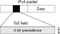
A 3-bit field in the IPv4 header, allowing traffic to be categorized into one of 8 priority levels, ranging from 0 (lowest priority) to 7 (highest priority).

Prioritizing traffic at the network edge when basic prioritization (like voice or video) is required.

Differentiated Services Code Point (DSCP)

A 6-bit field in the IP header used to classify traffic more granularly than IP precedence.

Common DSCP Values are:

  • Expedited Forwarding (EF): For real-time traffic such as voice and video (low latency)

  • Assured Forwarding (AF): For assured delivery of traffic, with different drop priorities.

  • Best Effort: For traffic that can be dropped during congestion if needed.

Fine-grained control over traffic, especially in large-scale networks where different types of traffic require varied treatment, such as real-time voice versus bulk data.

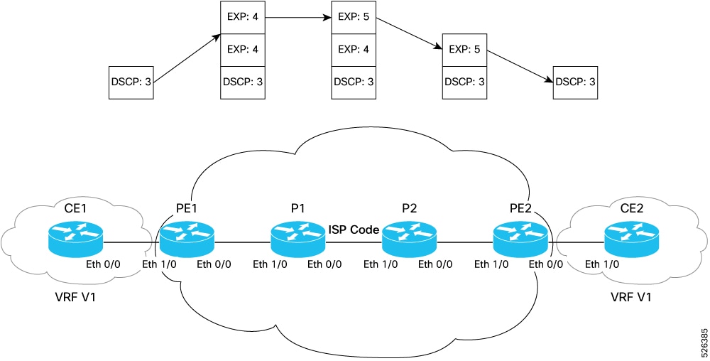
Experimental (EXP) bits in MPLS

A part of the MPLS label which uses 3 bits, allowing for 8 levels of priority.

MPLS VPNs and traffic engineering where precise control over traffic routing and prioritization is required.

Priority Code Point (PCP)

A 3-bit field in the Class of Service (CoS) portion of an Ethernet frame. It is used to prioritize Layer 2 (Ethernet) traffic. PCP values range from 0 to 7, with 0 being the lowest and 7 being the highest priority.

Ethernet networks and VLANs where Layer 2 traffic needs to be prioritized, such as voice traffic in a VLAN.

Drop Eligibility Indicator (DEI)

A part of the CoS field in the Ethernet header which indicates whether a packet is eligible to be dropped during congestion.

Ethernet networks where low-priority traffic (such as best-effort data) should be dropped first during periods of congestion.

QoS group

A technique to classify traffic based on QoS group numbers.

Grouping traffic flows for specialized handling or service-level agreements

Access Control Lists (ACLs)

A technique to classify traffic by matching specific attributes such as IP address, protocol type, and port numbers.

Custom traffic filtering or when you need to define very specific conditions for traffic classification.

The sections that follow focus on IP Precedence as an illustration of how typical packet classification techniques work.

IP Precedence to prioritize traffic

IP Precedence is a method for prioritizing network traffic by assigning a priority level to IP packets. It uses the first 3 bits of the Type of Service (ToS) field in the IPv4 header, allowing for 8 different priority levels (0-7). Each precedence level has a corresponding name defined in RFC 791.

Figure 1. Type of Service field in IPv4 header

Advantages of IP Precedence

  • Differentiated Services (DiffServ): You can assign higher priority to critical traffic (for example, VoIP) and lower priority to less time-sensitive traffic. You can do this by setting precedence levels and combining them with QoS queuing features to ensure service differentiation.

  • End-to-end QoS: When you set IP Precedence at the edge of your network, core network devices can enforce QoS policies based on those markings, ensuring consistent prioritization across the network.

  • Integration with QoS features: You can use IP Precedence with features like Low Latency Queuing (LLQ) and traffic shaping to manage congestion and bandwidth allocation.

  • Layer 2 mapping: You can map IP Precedence (Layer 3) values to Class of Service (CoS) values at Layer 2 (in the 802.1Q VLAN tag), extending QoS policies across different network segments.

Considerations for deploying IP Precedence in packet classification

  • Edge deployment: IP Precedence is usually deployed as close to the edge of the network or administrative domain as possible. This allows core network devices to implement QoS based on the precedence already set.

  • Reserved values: IP Precedence bit settings 6 and 7 are reserved for network control traffic, such as for routing updates. These values must not be used for user traffic.


  • Class-based marking and LLQ: Class-based unconditional packet marking and Low Latency Queuing (LLQ) features can use IP Precedence to classify and prioritize traffic.

How IP Precedence Works

Summary

The key components involved in applying IP Precedence are:

  • Edge router: Classifies and marks incoming traffic by setting the IP Precedence value in the packet header.

  • Policy map: Defines QoS policies that specify how traffic is handled based on its precedence level.

  • Network devices (such as core routers and switches): Reference the IP Precedence value to enforce traffic handling policies such as prioritization, bandwidth allocation, and congestion management.

The IP Precedence process involves marking packets at the edge of the network and applying QoS policies throughout the network path. The edge router assigns a precedence value to each packet based on policy configurations. This value is used by downstream devices to prioritize traffic, allocate bandwidth appropriately, and manage congestion.

Higher-precedence traffic is given preferential treatment in queuing and transmission, ensuring that critical applications—such as voice and video—are delivered with lower latency and better performance.

The process occurs in real time as packets are received and forwarded through the network. This ensures consistent traffic prioritization from edge to core.

Workflow

These stages describe the IP Precedence classification process:

  1. Edge router sets the IP Precedence value in the packet’s IPv4 header based on configured classification policies.

  2. Policy map defines how traffic should be treated based on the assigned IP Precedence value. This includes prioritization, bandwidth allocation, and congestion behavior.

  3. Network devices (such as core routers and switches) read the IP Precedence value and determine the appropriate handling of the packet:

    1. Prioritize higher-precedence packets in the queue.

    2. Allocate bandwidth as defined by the policy map.

    3. Drop lower-precedence packets first during congestion.

  4. All network devices continue to forward packets through the network, consistently applying QoS actions based on the IP Precedence value set at the edge.

Packet classification systems on your router

Your router uses two packet classification systems to determine traffic marking and policy application.

Traffic direction

Classification system

Ingress

QoS map and Ternary Content Addressable Memory (TCAM) are used to classify incoming traffic.

Egress

Only QoS map is used to classify outgoing traffic.

Selection of classification system

Your router determines the classification system based on the match conditions you configure in the QoS policy.

  • The router uses the QoS map when the policy matches on any of these fields:

    • DSCP

    • EXP

    • PCP

    • DEI

    • QoS group

  • If the match conditions do not include these fields, the router uses TCAM for classification.

Ternary Content Addressable Memory (TCAM) extends the concept of the Content Addressable Memory (CAM) table.

The table compares CAM and TCAM by match capabilities, use cases, and advantages in traffic classification.

Table 3. Comparison of CAM and TCAM

Attribute

CAM

TCAM

Match type

Exact match (0 or 1)

Ternary match (0, 1, or a wild card or “don’t care”)

Use case

MAC address lookup, switch port mapping

QoS policy classification, ACLs

Advantage

Enables fast lookups for simple key-value queries

Supports complex and flexible matching conditions

Traffic classes in QoS

The purpose of traffic classes is to define the criteria for identifying a specific type of traffic. Each class includes a name, match conditions, and logic to evaluate those match conditions. Traffic that matches a defined class is assigned to that class and treated according to the associated QoS policy.

Components of a traffic class

Component

Description

Name

The identifier assigned to the traffic class.

Match commands

The criteria used to classify packets

Match evaluation logic

Specifies whether the packet must match any or all defined conditions.

Packet classification behavior

When a packet arrives at the router, it is compared against the match commands defined in the traffic class. This table describes how the router classifies packets.

Classification case

Behavior

Packet matches class criteria

  • The packet is considered a member of that class, and

  • it is handled according to the QoS settings in the associated traffic policy.

Packet does not match any criteria

It is assigned to the default traffic class, which applies default forwarding behavior.

Traffic class configuration criteria

Match conditions

  • You can specify multiple values for the same match type in a single line of configuration. If the first value doesn’t match, the next value in the match statement is considered for classification.

  • You can use the not  keyword with a match command to classify traffic that does not match specific values.

  • Although all match commands are optional, you must configure at least one match criterion to define a valid traffic class.

Supported match types

Match Type Supported

Min, Max

Max Entries

Support for Match NOT

Support for Ranges

Direction Supported on Interfaces

IPv4 DSCP

IPv6 DSCP

(0,63)

64

Yes

Yes

Ingress

DSCP

Egress

IPv4 Precedence

IPv6 Precedence

(0,7)

8

Yes

No

Ingress

Precedence

Egress

MPLS Experimental Topmost

(0,7)

8

Yes

No

Ingress

Egress

Access-group

Not applicable

8

No

Not applicable

Ingress

Match qos-group

(1-31)

7 + class-default

No

No

Egress

Protocol

(0, 255)

1

Yes

Not applicable

Ingress

CoS

(0,7)

8

Yes

No

Ingress and Egress

DEI

(0,1)

2

Yes

No

Ingress and Egress

Match logic

  • The default behavior is match-any , where the packet must match at least one of the specified match statements for classification.

  • When you configure match-all , the packet must match all specified criteria to be considered part of the traffic class.

  • Although all match commands are considered optional, you must configure at least one match criterion to define a valid traffic class.

ACL considerations

  • The match access-group command does not support matching on packet length or time-to-live (TTL) fields.

  • When used in a class map, the ACL deny action is ignored. Traffic is classified solely on the basis of a match.

Egress classification rules

  • These match types are valid only in the egress direction:

    • match qos-group

    • match traffic-class

    • match dscp

    • match precedence

    • match mpls experimental (EXP)

  • The class-default implicitly matches qos-group 0 traffic.

  • You can classify traffic into up to seven distinct groups using match qos-group , with supported values ranging from qos-group 1 to qos-group 31 .

  • You cannot configure match qos-group 0 . In egress policies, qos-group 0 traffic is automatically matched by class-default .

Multicast and egress QoS handling

  • On your routers, multicast and unicast traffic follow different paths but converge at the egress in a fixed 20:80 multicast-to-unicast ratio per interface.

  • Egress QoS for multicast traffic treats traffic classes 0–5 as low-priority and traffic classes 6–7 as high priority. This prioritization behavior is not user-configurable.


  • Egress shaping does not apply to multicast traffic in high-priority traffic classes. Shaping is only effective for unicast traffic in these classes.

Ingress and egress traffic class considerations

  • If you assign a traffic class at ingress and do not define a matching class at egress, then the traffic will not be counted in the class-default at the egress policy map.

  • Only traffic class 0 maps to the egress class-default. Any non-zero traffic class assigned at ingress, but not mapped to an egress class or queue, will not be included in either the default class or any other class at egress.

Default traffic class behavior

  • Packets not matching any explicitly user-defined class are assigned to the default class (class-default .)

  • The default class always exists, even if not explicitly configured.

  • If no QoS actions are configured for the default class, packets receive no treatment—no marking, policing, shaping, or prioritization.

  • To apply QoS to unclassified traffic, configure actions under the default class in a policy map.

Layer 2 classification using Layer 3 headers

From Cisco IOS XR Release 7.2.12, classification on Layer 2 transport interfaces using Layer 3 header fields is supported. This capability is limited to physical and bundle main interfaces and does not apply to sub-interfaces.

Elements and supported actions of a traffic policy

Traffic policies define the QoS actions for traffic that matches one or more classes. These policies enforce how classified traffic is marked, shaped, policed, or prioritized on a router.

Elements of a traffic policy

A traffic policy contains these elements:

  • Name: Identifies the traffic policy. The name is referenced when you apply the policy to an interface.

  • Traffic class association: Specifies one or more traffic classes (defined using class-map) to include in the policy. The Modular QoS CLI (MQC) allows multiple traffic classes within a single policy.

  • QoS actions: Defines the actions to be applied to each traffic class. Supported actions include marking, policing, shaping, prioritizing, and queuing traffic.

Order of traffic class entries in a policy map

The order of class entries in a policy map determines how hardware evaluates the match rules.

  • Class match rules are programmed into the TCAM in the order specified in the policy map.

  • If a packet matches multiple classes, only the first matching class is used and only its configured actions are applied.

Number of classes per policy map

You can configure:

  • up to 8 traffic classes per ingress policy map, and

  • up to 8 traffic classes per egress policy map.

Supported QoS actions in a traffic policy map

In the MQC, you apply specific QoS actions in a policy-map after classifying traffic via class-map.

The table

  • outlines the supported actions

  • specifies the direction (ingress or egress) in which each action can be applied and,

  • helps prevent configuration errors by guiding you to apply only valid combinations.

Table 4. QoS actions supported in policy maps

QoS action

Direction

Notes

bandwidth remaining

Egress

Configures remaining bandwidth allocation for a class.

mark

Ingress and egress

See Packet Marking for marking options.

police

Ingress

Applies a traffic policing action.

priority

Egress

Supports priority levels 1 to 7.

queue-limit

Egress

Sets a threshold for queue depth.

shape

Egress

Configures traffic shaping per class.

red

Egress

Enables Random Early Detection (RED). Supports discard-class values:

  • 0—typically associated with default or lower-priority discard behavior.

  • 1—often used for slightly higher-priority traffic, still eligible for drop under congestion.

Configure packet classification and specify QoS actions

Use this task to classify traffic into user-defined classes and apply QoS actions such as traffic shaping. This helps manage bandwidth and prioritize traffic on an interface.

To classify and shape outgoing traffic, you apply a traffic policy to an interface. Classification is based on match criteria, such as QoS groups. Shaping controls the transmission rate of classified traffic.

Before you begin

Determine the match criteria for classifying traffic and the QoS actions based on the interface bandwidth.

Procedure


Step 1

Create a class map and specify the match criteria.

Example:

Router#configure
Router(config)#class-map match-any qos-1

This example creates a class map named qos-1 and specifies that traffic is matched if any of the defined conditions are met.

Step 2

Match traffic with QoS group 1 to the qos-1 class.

Example:

Router(config-cmap)#match qos-group 1
Router(config-cmap)#end-class-map
Router(config-cmap)#commit

QoS groups are internal markers that may be set based on ACLs, routing protocols, or other criteria.

Step 3

Create a policy map named test-shape-1 .

Example:

Router(config)#policy-map test-shape-1

Step 4

Bind or associate the qos-1 class to the policy map.

Example:

Router(config)#policy-map test-shape-1

Step 5

Specify QoS actions for the traffic class.

Example:

Router(config-pmap-c)#shape average percent 40
Router(config-pmap-c)#exit
Router(config-pmap)#end-policy-map

This example configures the policy to shape traffic in the qos-1 class to 40% of the interface bandwidth.

Step 6

Attach the traffic policy to an interface.

Example:

Router(config)#interface fourHundredGigE 0/0/0/2
Router(config-int)#service-policy output test-shape-1
Router(config-int)#commit

This example applies the policy map to the egress-direction of interface FourHundredGigE 0/0/0/2 .

Step 7

Verify policy configuration and traffic statistics.

Example:


Router# show qos interface fourHundredGigE 0/0/0/2 output

NOTE:- Configured values are displayed within parentheses
Interface FourHundredGigE0/0/0/2
  ifh 0x80000080 -- output policy
  NPU Id:                   0
  Total number of classes:    2
  Interface Bandwidth:        400000000 kbps
  Policy Name:                test-shape-1
  Accounting Type:            Layer1 (Include Layer 1 encapsulation and above)
------------------------------------------------------------------------------
Level1 Class
  =                      qos-1
    Level2 Class

Level1 Class
  =                      class-default

Node 0/0/CPU0, Interface FourHundredGigE0/0/0/2 Ifh 0x80000080 (FourHundredGigE) -- output policy
NPU Id:                                  0
Total number of classes:                   2
Interface Bandwidth:               400000000 kbps
Policy Name:                           test-shape-1
Accounting Type:                      Layer1 (Include Layer 1 encapsulation and above)
------------------------------------------------------------------------------
Level1 Class
  =                      qos-1
    Shape Average Rate(kbps)           160000000 (40%)
    Queue ID                             50331648 (LP queue)
    Tail Drop Packets                         0
    Tail Drop Bytes                           0

Level1 Class
  =                      class-default
    Queue ID                             50331647 (LP queue)
    Tail Drop Packets                         0
    Tail Drop Bytes                           0

The Shape Average Rate (kbps) 160000000 (40%) line shows the configured shaping rate (160 Gbps), which accounts for 40% of the 400 Gbps interface bandwidth.


Configure QoS actions for the default class

Use this task to apply a QoS marking action to unclassified traffic (the class-default class) in a traffic policy.

Traffic that does not match any user-defined class is automatically treated as part of the class-default class. Applying actions to this class ensures that even unclassified traffic receives appropriate QoS treatment, such as DSCP marking.

Use these steps to configure QoS actions for the default class.

Before you begin

Ensure that no other policy is applied to the same interface that would conflict with this default class policy.

Procedure


Step 1

Define a traffic policy and assign the default class.

Example:

Router# configure
Router(config)# policy-map egress_policy1
Router(config-pmap)# class class-default

This step creates a policy map named egress_policy1 and selects the class-default class, which handles all unmatched traffic.

Step 2

Set the QoS action—in this example, the DSCP value—for the default class.

Example:

Router(config-pmap-c)# set dscp default
Router(config-pmap-c)# exit
Router(config)# commit
This step marks all unclassified traffic with the DSCP value default (equivalent to DSCP 0 ), which typically indicates best-effort service.

The policy map egress_policy1 is created, and unclassified traffic is marked with DSCP 0 when the policy is applied to an interface.

Additional Guidelines for Packet Classification and QoS Actions

  • Hierarchical policy limitation: You cannot nest one policy map inside another or reference a policy map within another policy. Hierarchical policies are not supported.

  • Traffic rate accuracy: Traffic rate estimates in QoS statistics are approximations based on an exponential decay filter and may not reflect precise values.

  • BGP Flowspec impact: When a Flowspec police rule and a QoS policy apply to the same ingress traffic, the Flowspec action takes precedence. This may cause QoS counters for the policy map to display zero or incorrect values.

Enhanced Running Configuration Display for Policy Maps and Class Maps

Enhanced running configuration displays are CLI output improvements that

  • display each class map or policy map configuration instance on a separate line

  • improve readability of QoS configurations, and

  • aid in easier verification and troubleshooting.

Table 5. Feature History Table

Feature Name

Release Information

Feature Description

Enhanced Running Configuration Display for Policy Maps and Class Maps

Release 25.2.1

Introduced in this release on: Centralized Systems (8400 [ASIC: K100]) (select variants only*)

*This feature is now supported on Cisco 8404-SYS-D routers.

Enhanced Running Configuration Display for Policy Maps and Class Maps

Release 24.4.1

Introduced in this release on: Fixed Systems (8700) (select variants only*)

*Enhanced running configuration display for policy maps and class maps is now supported on Cisco 8712-MOD-M routers.

Enhanced Running Configuration Display for Policy Maps and Class Maps

Release 24.2.11

You can view each class map or policy map running configuration instance on a separate line.

The feature modifies the output display of this command:

CLI: show run formal

Before this enhancement, the running configuration outputs for policy maps and class maps were compressed and difficult to read. With this enhancement, the show run formal command outputs each QoS component—such as class maps and their matches, or policy maps and their associated classes—on dedicated lines.

Running Configuration Example

The configuration example associates policy map p1 with the class maps DSCP and MPLS .

After the configuration, its show run formal running configuration is displayed.

/* class map DSCP */
        
Router# config 
Router(config)# class-map match-any DSCP 
Router(config-cmap)# match dscp 1  
Router(config-cmap)# end-class-map  
        
/* class map MPLS */  
  
Router(config)# class-map match-any MPLS 
Router(config-cmap)# match mpls experimental topmost 2  
Router(config-cmap)# end-class-map  

/* DSCP-to-p1 association */  
        
Router(config)#  policy-map p1
Router(config-pmap)# class DSCP
Router(config-pmap-c)# bandwidth remaining ratio 80
Router(config-pmap-c)# root
 
/* MPLS-to-p1 association */  
        
Router(config)#  policy-map p1
Router(config-pmap)# class MPLS
Router(config-pmap-c)# bandwidth remaining ratio 60
Router(config-pmap-c)# exit
Router(config-pmap)# end-policy-map  
Router(config)# commit

Verification

The show run formal running configuration displays each class map and policy map running configuration instance on a separate line.

Router# show run formal
..
class-map match-any DSCP match dscp 1 
class-map match-any MPLS match mpls experimental topmost 2 
policy-map p1 class DSCP bandwidth remaining ratio 80 
policy-map p1 class MPLS bandwidth remaining ratio 60
..

show run and show run formal running configuration comparison:

Table 6. Configuration output before and after enhancement

Display aspect

Before enhancement (show run command )

After enhancement (show run formal )

Class map output

Compressed or inline

Shown on a separate line

Policy map class association

Merged into single policy block

Shown per class, each on a separate line

Troubleshooting readability

Moderate-to-low

High


Note


Use the show run formal command instead of the show run command to view the enhanced QoS configuration display with clearly separated class map and policy map lines.