Congestion Avoidance

Congestion Avoidance

Congestion avoidance is a traffic management technique that

  • helps prevent buffer overflows in network queues by managing packet drops before queues reach full capacity

  • monitors queue thresholds, and

  • triggers early drops of lower-priority packets to maintain the availability of buffer memory.

Queueing for congestion avoidance

Queuing for congestion avoidance manages queue buffers to prevent memory overflow in the ASIC or NPU. When queues fill beyond set thresholds, low-priority packets are dropped early to preserve memory for critical traffic and maintain overall system performance.

Shaping and scheduling context

  • Shaping buffers packets within a queue to smooth bursty traffic and control the transmission rate.

  • Scheduling moves packets out of queues based on priority and available bandwidth, ensuring traffic flow continuity.

Table 1. Feature History Table

Feature Name

Release Information

Feature Description

Queueing for Congestion Avoidance

Release 25.2.1 Introduced in this release on: Centralized Systems (8400 [ASIC: K100]) (select variants only*)

*This feature is now supported on the Cisco 8404-SYS-D routers.

Queueing for Congestion Avoidance

Release 24.4.1

Introduced in this release on: Fixed Systems (8700) (select variants only*)

You can shape traffic to control the traffic flow from queues and also configure queues to ensure certain traffic classes get a guaranteed amount of bandwidth.

*This functionality is now supported on Cisco 8712-MOD-M routers.

Queueing for Congestion Avoidance

Release 24.3.1

Introduced in this release on: Modular Systems (8800 [LC ASIC: P100]) (select variants only*), Fixed Systems (8200) (select variants only*), Fixed Systems (8700 (P100, K100)) (select variants only*) ,

You can shape traffic to control the traffic flow from queues and also configure queues to ensure certain traffic classes get a guaranteed amount of bandwidth.

*This feature is supported on:

  • 88-LC1-12TH24FH-E

  • 88-LC1-52Y8H-EM

  • 8212-48FH-M

  • 8711-32FH-M

Queueing for Congestion Avoidance

Release 24.2.11

Introduced in this release on: Modular Systems (8800 [LC ASIC: P100]) (select variants only*)

By placing packets in different queues based on priority, queueing helps prevent traffic congestion and ensures that high-priority traffic is transmitted with minimal delay. You can shape traffic to control the traffic flow from queues and also configure queues to ensure certain traffic classes get a guaranteed amount of bandwidth. Queueing provides buffers to temporarily store packets during bursts of traffic and also supports strategies that enable dropping lower-priority packets when congestion builds up.

*This feature is supported on 88-LC1-36EH.

Queuing modes

Your router line cards support two fixed queuing modes—8 xVOQ and 4xVOQ—that determine how many VOQs and related memory resources the system allocates to every interface. Selecting the appropriate mode lets you balance traffic-class isolation against logical-interface scale and is a mandatory first step before you apply any interface-level QoS policy.

Remember


From Release 7.2.12 onward, all Layer 3 queuing capabilities also apply to Layer 2 physical and bundle interfaces, but not to their sub-interfaces.


Table 2. Comparison of 8xVOQ and 4xVOQ queuing modes

Attribute

8xVOQ

4xVOQ

VOQs per interface

8

4

Supported internal traffic classes

8 (TC0–TC7), each mapped to a separate VOQ

8 mapped to 4; traffic classes must be remapped in the QoS policy

Logical-interface scale

Standard

Approximately double (since fewer VOQs per interface, the system supports twice the interfaces)

Default queue hierarchy

P1 + P2 + 6 PN hierarchy (main interface default)

Same hierarchy, but applies to only four VOQs

Typical use case

Maximum traffic-class isolation

High interface fan-out (number of active interfaces per line card or NPU) where fewer dedicated VOQs are acceptable


Note


P1 + P2 + 6 PN refers to the default queuing and scheduling hierarchy where:

  • P1—one hardware queue reserved for the single most critical class (TC 7).

  • P2—one queue for the next-most-critical class (TC 6).

  • 6 PN—six normal-priority queues, one each for TC 5, 4, 3, 2, 1, 0

That adds up to the eight VOQs  that the  8xVOQ mode allocates per interface. If you move the router to 4xVOQ mode, TC7 still maps to P1 and TC 6 to P2, but the eight internal traffic classes must be remapped so that the four VOQs can carry multiple classes.

In both modes, queues are allocated per interface regardless of policy applied.


Switch the queuing mode on the router

Use this task to change the system-wide Virtual Output Queue (VOQ) mode—8xVOQ for maximum traffic-class isolation or 4xVOQ for greater interface scale.

The VOQ mode change applies to the entire chassis. The change takes effect only after every line card reloads, which interrupts traffic.

Before you begin

Make a list of interfaces (main, sub-interfaces, and bundles) with egress queuing service policies attached.

Follow these steps to switch the queuing mode on the router.

Procedure


Step 1

Verify the current VOQ mode.

Example:

Router#show hw-module profile qos voq-mode
Current system VOQ mode: 8

This command confirms the chassis is running in 8xVOQ mode before you begin.

Step 2

Detach every egress queuing service policy from all interfaces.

Example:

Router#configure
Router(config)#interface TenGigE0/0/0/0
Router(config-if)#no service-policy output Q-OUT
Router(config-if)#exit
Router(config)#interface Bundle-Ether10
Router(config-if)#no service-policy output Q-OUT
Router(config-if)#exit
! …repeat “no service-policy output …” for every main interface, sub-interface, and bundle
Router(config)#commit
Router(config)#exit

Remove only the egress queuing (service-policy output … ) bindings. Retain ingress classification or marking policies.

Step 3

Configure the new VOQ mode and commit.

Example:

Router#configure
Router(config)#hw-module profile qos voq-mode 4
Router(config)#commit
Router(config)#exit

The voq-mode 4  setting applies to the entire chassis and persists across future reboots.

Step 4

Reload all nodes to program the new mode into the ASICs.

Example:

Router#admin
Router(admin)#reload location all
Proceed with reload the following node(s): 0/0/CPU0 0/RP0/CPU0 [confirm] y

All line cards reload. Traffic is interrupted until the router returns to the IOS XR prompt.

Step 5

Verify that the router is now running in 4xVOQ mode.

Example:

Router#show hw-module profile qos voq-mode
Current system VOQ mode: 4

Successful output confirms the chassis is operating in the new VOQ mode.


What to do next

After the change, review your QoS policies to be sure each hardware queue now aggregates the intended traffic classes, especially when you reduce the queue count from 8 to 4.

Queuing policy for main interfaces

After you set the chassis to 8xVOQ or  4xVOQ (see Switch the Queuing Mode on the Router), each main interface automatically receives the queue hierarchy described here.
Use this information to verify how each internal traffic class is handle and to decide whether you need a custom egress-queuing policy on the main interface.

The 8xVOQ configuration allocates: P1 to TC 7, P2 to TC 6, and PN0–PN5 to TC 5 through 0. (See Queuing modes)

Next steps:

  • If the default priority and bandwidth distribution is acceptable, no further action is required.

  • To change scheduling weights, shaping rates, or WRED profiles, create an egress queuing policy and attach it to the main interface (see Attach a Queuing Policy to an Interface).

Queuing policy behavior on subinterfaces

Table 3. Feature History Table

Feature Name

Release Information

Feature Description

Subinterface Queueing Policy

Release 25.2.1

Introduced in this release on: Centralized Systems (8400 [ASIC: K100]) (select variants only*)

*This feature is now supported on the Cisco 8404-SYS-D routers.

Subinterface Queueing Policy

Release 24.4.1 Introduced in this release on: Fixed Systems (8700) (select variants only*)

You can manage traffic flows with fine granularity by configuring QoS policies at the subinterface level.

*This functionality is now supported on Cisco 8712-MOD-M routers.

Subinterface Queueing Policy

Release 24.3.1

Introduced in this release on: Modular Systems (8800 [LC ASIC: P100]) (select variants only*), Fixed Systems (8200) (select variants only*), Fixed Systems (8700 (P100, K100)) (select variants only*)Modular Systems (8800 [LC ASIC: P100]) , Fixed Systems (8200) , Fixed Systems (8700 (P100, K100)) (select variants only*)

You can manage traffic flows with fine granularity by configuring QoS policies at the subinterface level.

*This feature is supported on:

  • 88-LC1-12TH24FH-E

  • 88-LC1-52Y8H-EM

  • 8212-48FH-M

  • 8711-32FH-M

Subinterface Queueing Policy

Release 24.2.11

Introduced in this release on: Modular Systems (8800 [LC ASIC: P100]) (select variants only*)

To manage traffic flows with fine granularity, you can configure QoS policies at the subinterface level. Also, with QoS support on mixed Layer 2 and Layer 3 subinterfaces under the same main interface, you can ensure that multiple traffic types with varying QoS requirements coexist on a single main physical interface.

*This feature is supported on 88-LC1-36EH.

A subinterface uses the main interface VOQs by default. When you apply an egress queuing policy, the router allocates a dedicated set of VOQs—4 or 8, depending on the chassis-wide VOQ mode you selected earlier. Each subinterface can host up to three QoS policies (ingress, egress marking, and egress queuing). If you remove the egress-queuing policy later, its VOQs are released and the subinterface traffic reverts to the main interface queues.

Use this table to understand the limits and defaults that apply after a policy is attached.

Attribute

8xVOQ

4xVOQ

VOQs per sub-interface

8

4

Default hierarchy

P1 + P2 + 6 PN

P1 + P2 + 2 PN


Note


  • P1—one hardware queue reserved for the single most critical class (typically TC 7).

  • P2—one queue for the next-most-critical class (typically TC 6).

  • PN (normal priority queues):

    • In 8×VOQ mode—one queue each for TC5, TC4, TC3, TC2, TC1, and TC0 (six PN queues).

    • In 4×VOQ mode—one queue each for TC1 and TC0 (two PN queues)

A line card has a fixed pool of VOQs and scheduler state blocks, so there is a limit to the number of policies you can deploy before resources are exhausted. To monitor the remaining VOQ and scheduler resources by viewing packet and byte counts per traffic class, as well as drops, which can indicate resource constraints, run the show controllers npu stats voq command.


Next steps:

  1. Decide which traffic classes need their own scheduler or shaper.

  2. Configure an egress queuing policy that defines those actions.

  3. Apply the policy with service-policy output <policy-name>  under the subinterface.

  4. Verify that the policy is active with show qos interface .

Congestion detection and handling

Your router assigns a virtual output queue (VOQ) to each traffic class, which uses both on-chip packet buffers and high-bandwidth memory (HBM). If the VOQ becomes congested, the router places excess packets in HBM and applies congestion-control mechanisms such as dynamic drop thresholds or packet marking.

The table lists congestion detection and handling techniques. Each technique includes a brief description and an analogy to help you relate it to a real-world scenario.

Table 4. Congestion handling techniques and their analogies

Technique

Short Description

Highway Traffic Analogy

Tail drop and the FIFO queue

Drops incoming packets once the queue reaches its configured limit; processes packets in arrival order with no traffic differentiation.

Like a toll booth that shuts its gate when the line of cars reaches the maximum allowed length (no exceptions).

Congestion avoidance in VOQs

Moves a VOQ from on-chip Shared Memory System (SMS) to HBM when congestion thresholds are exceeded.

Like diverting cars from the main highway lane to an overflow lane when the main lane gets jammed.

Dual queue limit

Configures two queue thresholds—one for high-priority traffic and one for low-priority traffic—to ensure critical flows continue during congestion.

Like having an express lane that closes early to non-emergency vehicles so ambulances can always get through.

Equitable traffic flow using fair VOQ

Allocates dedicated Virtual Output Queues (VOQs) per source to destination port pair to ensure fair bandwidth distribution across ports.

Like giving every on-ramp its own dedicated lane to the highway so no one ramp hogs the traffic flow.

Random Early Detection and TCP

Randomly drops packets before queues fill to signal senders to slow down, preventing sudden congestion.

Like a traffic light that occasionally turns red early to prevent gridlock at an intersection.

Explicit Congestion Notification

Marks packets instead of dropping them to signal congestion, preserving flow without packet loss.

Like flashing a warning sign telling drivers to slow down before a traffic jam, instead of stopping them completely.

Virtual Output Queue Watchdog

Detects and clears VOQs that are stuck and not transmitting, even when packets are queued.

Like a traffic sensor detecting a blocked lane and triggering a tow truck to clear it.

Tail drop and the FIFO queue

A tail-drop queue management method is a congestion avoidance mechanism that:

  • discards new packets once the output queue is full

  • treats every flow identically and,

  • operates on a first-in-first-out (FIFO) buffer that drains at the line-rate of the interface.

Key attributes of tail drop queue management

This table helps you understand the main features of tail drop queuing, including its discipline, drop policy, fairness, and how it is typically used to manage congestion.

Attribute

Description

Queue discipline

Packets exit in the order in which they arrive (First In, First Out).

Drop policy

When the queue reaches its limit, each subsequent packet is dropped until the backlog decreases below the limit.

Fairness

Does not differentiate between classes of traffic. It works best when simple best-effort service is acceptable.

Typical use

Basic congestion protection, especially on devices or on network links with limited buffer memory. It is commonly used as a default-queue management mechanism. You can also use tail drop as a foundation for more advanced QoS policies, such as priority queuing with explicit queue limits.

How tail drop works

In packet-switched networks, congestion occurs when traffic arriving at an interface exceeds the available buffer capacity.

Tail drop is a common approach. When the queue reaches its configured limit, all subsequent packets are discarded until space becomes available. This mechanism protects buffer memory and provides a straightforward form of congestion control.

Summary

The tail drop process consists of these key components:

  • Queuing subsystem: Enqueues incoming packets until the queue limit is reached.

  • Scheduler: Dequeues and transmits packets in FIFO order from the output queue.

  • Packet sender: Retransmits packets that are dropped.

Packets are enqueued in FIFO order until the queue reaches its configured limit. At that point, any new packets are tail-dropped (discarded). The sender must retransmit those packets. Once the scheduler transmits enough packets and the queue depth falls below the limit, enqueuing resumes.

Enqueuing resumes after the scheduler transmits enough packets and the queue depth falls below the limit.

Workflow

These stages describe how the tail-drop process protects buffer memory on an egress queue.

  1. When the queuing subsystem enqueues a packet, it is accepted if the queue depth is below the queue limit.
  2. When a new packet arrives and queue depth equals the queue limit, the packet is tail-dropped and the sender must retransmit.
  3. The scheduler transmits packets in FIFO order from the output queue. If the queue depth falls below the limit, packet enqueuing resumes.

Guidelines for configuring tail drop thresholds

Always configure queue-limit with priority, shape average, bandwidth, or bandwidth remaining. The only exception is for the default class. If you do not follow this approach, the router rejects the policy commit.


Efficient use of rate class profiles with tail drop thresholds

Fine-tune tail drop threshold values so that multiple traffic classes can share the same rate class profile.

This principle applies when configuring tail drop thresholds on routers where each ASIC supports a maximum of 64 rate class profiles. Rate class profiles define performance characteristics such as bandwidth limits, priority levels, queuing policies, and drop thresholds.

Because each ASIC can support only 64 rate class profiles, creating a unique profile for every traffic class quickly consumes available hardware resources. By allowing multiple traffic classes with the same tail drop threshold to share a profile, you conserve hardware resources and design a more scalable system.

If you configure each traffic class with a unique tail drop threshold, the device may exhaust the limited pool of available rate class profiles. This can lead to inefficient hardware utilization and restrict further QoS configuration flexibility.

Review your traffic classes and adjust tail drop thresholds so that classes with similar performance needs use the same profile. This approach preserves rate class profiles for essential use cases. It also ensures that critical services receive the required bandwidth and latency treatment.

Configure a tail drop threshold for a traffic class

Use this task to define the maximum queue length for a traffic class and set service attributes, so that packets beyond this limit are dropped.

You configure tail drop for a class in a policy map and then attach the policy map to an interface. You must specify queue limits and set either priority, average shaping, or bandwidth for non-default classes.

Before you begin

  • Determine your traffic class and required tail drop threshold.

  • Identify the interface for policy attachment.

Follow these steps to configure a tail drop threshold for a traffic class.

Procedure

Step 1

Define a class map and match the traffic class.

Example:
Router(config)#class-map qos-1
Router(config-cmap)#match traffic-class 1
Router(config-cmap)#commit

This step specifies the match criterion for a class map. In this example, packets belonging to class 1 are matched. Only traffic identified as class 1 will be selected for the policy actions associated with this class map.

Step 2

Create or modify a policy map and assign the class.

Example:
Router(config)#policy-map test-qlimit-1
Router(config-pmap)#class qos-1

This example  specifies a class named qos-1  within the policy map for further configuration. 

Step 3

Set the queue limit for the selected class.

Example:
Router(config-pmap-c)#queue-limit 100 us

This example sets the maximum queue length for the class to the buffer depth that corresponds to 100 microseconds of traffic at the interface rate. Packets arriving after this limit is reached are dropped (tail drop).

Step 4

Assign a priority level to the class.

Example:
Router(config-pmap-c)#priority level 7

Step 5

Enter interface configuration mode for the specified interface.

Example:
Router(config)#interface HundredGigE 0/6/0/18

Step 6

Apply the QoS policy map to the interface for outbound traffic.

Example:
Router(config)#interface HundredGigE 0/6/0/18
Router(config-if)#service-policy output test-qlimit-1
Router(config-if)#commit

This example attaches the policy map named test-qlimit-1  to the interface as an output (egress) service policy. All traffic leaving the interface is subject to the QoS rules defined in test-qlimit-1 .

Step 7

Verify the tail drop and queue configuration on an interface.

Example:
Router#show qos int hundredGigE 0/6/0/18 output 
Interface HundredGigE0/6/0/18 ifh 0x3000220  -- output policy
 
NPU Id:                        3
Total number of classes:       2
Interface Bandwidth:           100000000 kbps
VOQ Base:                      11176
VOQ Stats Handle:              0x88550ea0
Accounting Type:               Layer1 (Include Layer 1 encapsulation and above)
 
------------------------------------------------------------------------------
 
Level1 Class (HP7)                       =   qos-1
Egressq Queue ID                         =   11177 (HP7 queue)
TailDrop Threshold                       =   1253376 bytes / 100 us (100 us)
WRED not configured for this class
 
Level1 Class                             =   class-default
Egressq Queue ID                         =   11176 (Default LP queue)
Queue Max. BW.                           =   101803495 kbps (default)
Queue Min. BW.                           =   0 kbps (default)
Inverse Weight / Weight                  =   1 (BWR not configured)
TailDrop Threshold                       =   1253376 bytes / 10 ms (default)
  • qos-1  is shown as a high-priority class (HP7 ) with a queue-limit of 100 us.

  • The class-default  queue uses default values and does not have explicit priority or queue limit overrides.

  • Both classes show WRED not configured for this class because Weighted Random Early Detection (WRED) was not set.


The specified class will drop packets at the configured queue threshold, optimizing queue behavior according to the class’s service requirements.

Congestion avoidance in VOQs

Congestion avoidance in a VOQ protects the on-chip Shared Memory System (SMS) from overruns. When a VOQ’s SMS occupancy exceeds its eviction threshold, subsequent packet buffers for that VOQ are allocated from High-Bandwidth Memory (HBM). While the VOQ uses HBM, congestion controls from its policy map, such as Random Early Detection (RED) or Explicit Congestion Notification (ECN), apply. If no congestion controls are configured, the queue relies on tail drop. When the occupancy falls below the return threshold, buffer allocation shifts back to SMS.

Shared Memory System (SMS): SMS is the on-chip packet-buffer subsystem that provides primary buffer space for each virtual output queue (VOQ) under normal traffic conditions. It offers low latency and serves as the first stage of packet storage before any spillover to external memory.
High-Bandwidth Memory (HBM): HBM is an external, high-capacity packet-buffer attached to the NPU. When a VOQ’s SMS occupancy exceeds its eviction threshold, subsequent packet buffers for that VOQ are allocated from HBM. Once the queue drains below the return threshold, buffer allocation shifts back to SMS.

Remember


RED applies only to VOQs that are currently in HBM. Weighted Random Early Detection (WRED) is not supported.


Dual queue limit

A dual queue limit is a pair of length thresholds that

  • gives you flexibility to set two queue limits on a single policy map


  • an egress VOQ enforces based on the discard class—0 for low-priority or 1 for high-priority traffic—that you mark on the packets in an ingress policy, and


  • keeps critical traffic flowing even when buffer space is scarce.

Queue threshold limits for discard classes

When the queue grows:

  • packets marked discard-class 1  stop being enqueued once the queue length reaches the lower limit.

  • packets marked discard-class 0  can continue to fill the queue until it reaches the higher limit; only then are those packets dropped. 

Guidelines for configuring dual queue limits

This reference lists the guidelines you must follow when configuring dual queue limits. Dual limits use two thresholds (for discard-class 0 and discard-class 1 ) to control how different priority packets are dropped as the queue grows. Observing these guidelines ensures predictable drop behavior, prevents invalid configurations, and accounts for how NPUs enforce thresholds.
Table 5. Guidelines and rationale while configuring dual queue limits

Guideline

Rationale

Use the same unit—bytes, packets, or time—for both limits.

Mixed units are rejected. 

Set the discard-class 0 limit so that it is higher than the discard-class 1 limit.

Enforces a logical and deterministic drop behavior, ensuring that higher priority traffic is less likely to be dropped compared to lower priority traffic. Reversed values are rejected to maintain proper queue management and traffic prioritization.

Configure both limits to ensure a valid configuration. Defining only one discard class makes the queue limit invalid

By configuring both discard-class 0 and discard-class 1 limits, the router avoids ambiguous or undefined drop actions. This means that when the queue reaches these thresholds, packets are dropped in a controlled and expected manner according to their priority and limits.

Configure the thresholds per your requirement. The ASIC rounds each threshold value to the nearest hardware buffer block size.

Each NPU enforces limits only in fixed-size buffer blocks. Any value you enter is converted to the closest multiple, so the number shown in show qos interface output may differ slightly from what you configured, but the enforced limit matches that rounded value.


Remember


Dual limits protect against loss, not necessarily latency. This is because priority traffic may experience delays behind large low-priority bursts.


Configure dual queue limits

Before you begin

Ensure that packets are already classified and marked with discard-class 0  or discard-class 1  on ingress.

Follow these steps to configure dual queue limits on an egress policy map.

Procedure

Step 1

Create the egress policy map.

Example:
router(config)#policy-map EGRESS_DQL

Step 2

Enter the class that requires the dual limit.

Example:
router(config-pmap)#class TC7

Step 3

Set the high-priority threshold.

Example:
router(config-pmap-c)#queue-limit discard-class 0 100 mbytes

This example specifies that packet drops (or, RED or ECN marking, if configured) start when the queue’s total occupancy for all packets reaches about 100 MB. The NPU rounds this value to the nearest hardware buffer-block size before enforcing it.

Step 4

Set the low-priority threshold.

Example:
router(config-pmap-c)#queue-limit discard-class 50 mbytes

This example specifies that the queue start dropping (or marking) packets as soon as the total queue occupancy reaches about 50 MB.

Step 5

(Optional) Make the class strict-priority.

Example:
router(config-pmap-c)#priority level 1
router(config-pmap-c)#exit
 

This example instructs the scheduler to treat this class as strict-priority (low-latency) traffic. The class still follows the discard-class thresholds you set earlier (discard-class 1 drops at ~50 MB; discard-class 0 drops at ~100 MB).

Step 6

(Optional) Specify a bandwidth remaining weight for the default class.

Example:
Router(config-pmap)#class class-default
router(config-pmap-c)#bandwidth remaining ratio 1
router(config-pmap-c)#exit
 

This is an optional step. If you omit this command, the bandwidth remaining ratio defaults to 1.

Step 7

Verify that the dual queue limits are active on the egress interface.

Example:
Router#show qos interface hundredGigE 0/0/0/30 output 
NOTE:- Configured values are displayed within parentheses Interface HundredGigE0/0/0/30 ifh 0xf000210 -- output policy NPU Id:     0
Total number of classes:                  2
Interface Bandwidth:           100000000 kbps
Policy Name:                  egress_pol_dql
VOQ Base:                                                     464
Accounting Type:              Layer1 (Include Layer 1 encapsulation and above) VOQ Mode:    8
Shared Counter Mode:                           1
 Level1 Class (HP1)           = tc7
Egressq Queue ID              =          471 (HP1 queue)
Queue Max. BW.                =          no max (default)
Discard Class 1 Threshold     =  25165824 bytes / 2 ms (50 mbytes)
Discard Class 0 Threshold     =  75497472 bytes / 5 ms (100 mbytes)

WRED not configured for this class

Level1 Class                  =       class-default
Egressq Queue ID              =       464 (Default LP queue)
Queue Max. BW.                =       no max (default)
Inverse Weight / Weight       =      1 / (1)
TailDrop Threshold            =      749568 bytes / 6 ms (default)

WRED not configured for this class


What to look for:

  • Discard Class 1 Threshold shows the lower limit (~ 50 MB, rounded to the nearest hardware block).

  • Discard Class 0 Threshold shows the upper limit (~ 100 MB, also rounded).

  • Both values confirm enforcement of the dual-queue-limit pair on egress queue ID 471 for class tc7 .

  • class-default appears separately with its own tail-drop threshold and bandwidth-remaining weight. This is not affected by the dual limits.


Equitable traffic flow using fair VOQ

A Fair Virtual Output Queue (VOQ) is a queuing-allocation mechanism that

  • allocates a dedicated VOQ for every source-port and destination-port pair

  • distributes the bandwidth of each destination port evenly across all requesting source ports, and

  • supports 4-queue (fair-4) or 8-queue (fair-8) modes that you enable with hw-module profile qos voq-mode .

Per default behavior, an NPU slice shares four or eight VOQs per destination port; multiple source ports can therefore compete for the same queue and starve each other. Fair VOQ removes that contention by giving every port its own VOQ.

Table 6. Feature History Table

Feature Name

Release Information

Feature Description

Equitable Traffic Flow Using Fair VOQ on Cisco 8201-32FH Routers

Release 7.5.2

You can now ensure that the bandwidth available at the destination port for a given traffic class is distributed equally to all source ports requesting bandwidth on Cisco 8201-32FH routers.

Equitable Traffic Flow Using Fair VOQ

Release 7.3.3

Configuring this feature ensures that ingress traffic from various source ports on every network slice of an NPU is assigned a unique virtual output queue (VOQ) for every source port and destination port pair. This action ensures that the bandwidth available at the destination port for a given traffic class is distributed equally to all source ports requesting bandwidth.

In earlier releases, the traffic wasn’t distributed equitably because each slice wasn’t given its fair share of the output queue bandwidth.

This feature introduces the fair-4 and fair-8 keywords in the hw-module profile qos voq-mode command.

Balancing traffic shares between slices

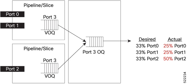
Consider two 100 G ports (port 0 and port 1) on slice 0 and one 100 G port (port 3) on slice 1, all sending traffic to the same destination port.

Without Fair VOQ, port 0 and port 1 share a single ingress VOQ and each receives ~25 % of the egress buffer traffic. The ingress VOQ in slice-1 is available exclusively for port-3, so port 3 receives ~50 % of the buffer traffic.

Figure 1. Existing behavior : Source ports on slice share one VOQ per destination port


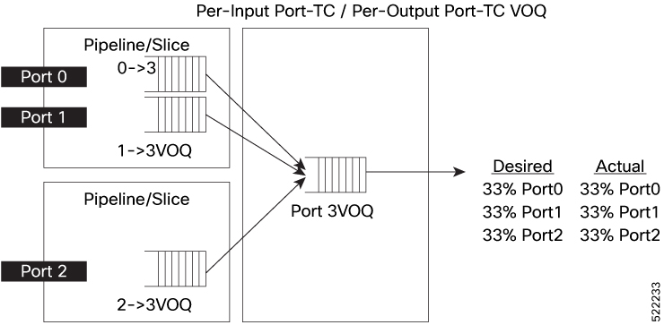
With Fair VOQ enabled, each ingress port has its own VOQ, so all three ports receive an equal 33 % share.

Figure 2. Fair VOQ behavior: each source port on slice has one dedicated VOQ per destination port 


Configuration options for fair VOQ modes and sharing of counters

You can configure fair VOQ for 8xVOQ mode (fair-8 ) and 4xVOQ mode (fair-4 ) using these options in the hw-module profile qos voq-mode command:
  • hw-module profile qos voq-mode fair-8

  • hw-module profile qos voq-mode fair-4

You can also share VOQ statistics counters in both fair VOQ modes. The table presents the supported counter options and other relevant information. (For details on why sharing counters is essential and how to configure counters sharing, see Sharing of VOQ statistics counters.)

Table 7. Fair VOQ modes and sharing counters

Fair VOQ mode

Dedicated counter (1 per VOQ)

Two VOQs share a counter

Four VOQs share a counter

Notes

fair-8

Not supported

Supported

Supported

Dedicated counters not supported in fair-8 mode. Use 2-per-counter for non-breakout and 4-per-counter for 4x breakout.

fair-4

Supported

Supported

Supported

Recommended: 2-per-counter for non-breakout, 4-per-counter for 4x breakout.

Guidelines and limitations for fair VOQ

Router support

Fair VOQ is available only on:

  • Cisco 8202 routers—12 × QSFP56-DD 400 G ports and 60 × QSFP28 100 G ports.

  • Cisco 8201-32FH routers—32 × QSFP-DD 400 G ports.

Router reload required

After you configure hw-module profile qos voq-mode in the fair-4 or fair-8 mode (and the matching counter-sharing value), you must reload the router for the new VOQ map to take effect.

Layer 2 traffic not supported

You cannot use fair VOQ for bridged (Layer 2) frames in either fair-4 or fair-8 mode because these frames are forwarded by slice-level queues.

Subinterface queuing unsupported

You cannot attach egress queuing service-policies to subinterfaces or bundle subinterfaces when fair VOQ is enabled, because those policies require dedicated VOQs. However, egress marking policies on subinterfaces are still supported.

ERSPAN mirroring traffic unsupported

If you rely on Encapsulated Remote Switched Port Analyzer (ERSPAN), disable fair VOQ because ERSPAN session traffic bypasses the fair VOQ mechanism.

Counter-sharing restrictions

hw-module profile stats voqs-sharing-counters 1 is not supported with fair-8 . Configure one of these valid pairs before you reload:

  • voq-mode fair-8 with voqs-sharing-counters 2 or 4

  • voq-mode fair-4  with voqs-sharing-counters 1, 2, or 4

If your applications use many hardware counters, do not use counter-share 2 because it may exhaust the available pool.

In these environments, use counter-share 4 or dedicated counters in fair-4 mode.

Breakout limited to 400 G ports

In fair VOQ mode (fair-4 or fair-8 ) on Cisco 8202 routers, physical-layer breakout is supported only on 400 G ports. 100 G breakout ports inherit their parent’s VOQ allocation

Additional CLI visibility

When you enable fair VOQ, the show controllers npu stats voq command adds the src-interface (logical ingress interface) and src-slice (NPU slice ID) fields. These fields are absent in slice-based VOQ mode.

Maximum supported interfaces by fair VOQ and counter sharing modes

The table shows how many interfaces are supported with only basic IPv4 settings—no QoS policies, ACLs, or sub-interfaces configured—under each combination of VOQ mode and counter-sharing option.
Table 8. Maximum interfaces based on fair VOQ Mode and counter sharing modes

VOQ Mode

Sharing Counter Mode

Maximum Interfaces for Cisco 8202

Maximum Interfaces for Cisco 8201-32FH

fair-8

1

The router doesn't support this combination.

The router doesn't support this combination.

fair-8

2

96 = 60 (100G) + 8x4 + 4 (400G) ==> you can configure only eight 400G interfaces in 4x10G or 4x25G breakout mode.

128 = 32x4 (4x10G or 4x25G - breakout on all 32 ports - 400G)

fair-8

4

108 = 60 + 12 x 4 (breakout on all 12 ports - 400G)

fair-4

1

96 = 60(100G) + 8x4 + 4 (400G) ==> you can configure only eight 400 G interfaces in 4x10G or 4x25G breakout mode.

fair-4

2

108 = 60 + 12 x4 (breakout on all 12 ports - 400G)

fair-4

4

108 = 60 + 12 x4 (breakout on all 12 ports - 400G)

Configure fair VOQ

Allocate a dedicated VOQ for every source-port and destination-port pair so that all ingress ports share egress buffers and scheduler time evenly.

Run this task on routers that support this feature when you need to remove slice-level VOQ contention. This configuration is typically used for 'many-to-one' traffic patterns, such as when many 100 G access links feed a few 400 G uplinks.

Before you begin

  • Choose your VOQ mode:

    • fair-8 : eight queues per port pair (finest statistics granularity)

    • fair-4 : four queues per port pair (largest interface scale)

Choose the counter sharing mode:

  • 4 : halves VOQ counter usage; best for routers that already track many ACL, QoS, or NetFlow statistics.

  • 2 : finer VOQ stats but doubles counter consumption; use only if you have free counter capacity.

Perform these steps on the active route processor.

Procedure

Step 1

Set the counter-sharing value.

Example:
Router(config)#hw-module profile stats voqs-sharing-counters 4

Replace 4 with 2 if finer VOQ accounting is needed and spare counters are available.

Step 2

Enable fair VOQ.

Example:
Router(config)#hw-module profile qos voq-mode fair-8

For higher port scales, choose fair-4 .

Note

 
If you configure fair-8 mode without counter sharing, configuration failures or unexpected behaviors may occur

Step 3

Commit the profile changes, then reload the entire chassis.

Example:
Router(config)#commit
Router#reload location all

Step 4

Verify that fair VOQ is active.

Example:
Router#show controllers npu stats voq ingress interface hundredGigE 0/0/0/20 instance 0 location 0/RP0/CPU0

 
Interface Name        =   Hu0/0/0/20
Interface Handle      =      f000118
Location              =   0/RP0/CPU0
Asic Instance         =            0
Port Speed(kbps)      =    100000000
Local Port            =        local
Src Interface Name    =          ALL
VOQ Mode              =       Fair-8
Shared Counter Mode   =            4
       ReceivedPkts    ReceivedBytes   DroppedPkts     DroppedBytes
-------------------------------------------------------------------
TC_{0,1} = 11110           1422080         0               0              
TC_{2,3} = 0               0               0               0              
TC_{4,5} = 0               0               0               0              
TC_{6,7} = 0               0               0               0 
Check for:
  • VOQ Mode : Fair-8

  • Shared Counter Mode : 4


The router runs in fair VOQ mode. Every ingress port owns eight dedicated queues per destination port, ensuring equitable buffer usage and scheduler time.

What to do next

If you need sub-interface queuing later, remove the profile (no hw-module profile qos voq-mode ), commit, and reload to return to slice-based VOQs.

Random Early Detection and TCP

Random early detection (RED) is a congestion avoidance mechanism that:

  • proactively manages queue lengths by randomly dropping packets before a queue becomes full

  • interacts with congestion control protocols such as Transmission Control Protocol (TCP) by signaling sources to reduce their transmission rate and,

  • helps maintain network stability and performance.

Understanding Random Early Detection Queue Size and TCP Congestion Control

  • RED operates on the average queue size—not the instantaneous queue size.

  • When RED is enabled, it starts dropping packets at a configurable rate as congestion occurs, prompting TCP senders to slow down.

RED packet drops for TCP congestion notification

If a network interface begins to experience congestion, RED randomly drops packets to notify TCP sources to reduce their sending rate before the queue overflows.

Random Early Detection as a traffic light for congestion control

RED is like a traffic light that occasionally turns red early to prevent cars from piling up at an intersection and smooth the overall flow.

Guidelines for configuring Random Early Detection

Recommendation for setting Random Early Detection thresholds

Configure Random Early Detection (RED) using the random-detect <min threshold> <max threshold> command with a maximum threshold higher than the system-supported minimum threshold value. This approach prevents configuration errors."

Requirement for configuring Random Early Detection with class policies

"When you configure random-detect on any class, including class-default, configure shape average or bandwidth remaining as well.

Caution when configuring queue limits

If you configure a queue-limit lower than the system minimum, the value changes to the supported minimum.

Tip for using Random Early Detection to smooth traffic flow

RED distributes packet drops over time, helping TCP adapt transmission rates gradually, which prevents sudden congestion and maintains low queue depths.

How Random Early Detection works

Random Early Detection (RED) is implemented on network devices to manage congestion by signaling Transmission Control Protocol (TCP) sources to adjust their sending rates before queue overflow occurs.

Summary

RED monitors the average queue size on an interface. When the average exceeds a minimum threshold, RED starts randomly dropping packets. If the average reaches a maximum threshold, all incoming packets may be dropped until congestion subsides. This proactive approach allows TCP to reduce its transmission rate, smoothing out traffic bursts and maintaining network performance.

Workflow

  1. The device calculates the average queue size.
  2. If the average queue size exceeds the minimum threshold, RED randomly drops incoming packets at a configured probability.
  3. TCP sources detect dropped packets, interpret this as congestion, and decrease their sending rates.
  4. As congestion clears and the average queue size decreases, the probability of drops is reduced, allowing normal transmission rates to resume.
    Table 9. Random Early Detection behavior based on average queue size

    When the average queue size

    Then

    is below the minimum threshold

    all packets are accepted.

    is between the minimum and maximum thresholds

    packets are randomly dropped with increasing probability.

    exceeds the maximum threshold

    all packets may be dropped.

Result

RED ensures that packet loss signals are spread over time, preventing global synchronization of TCP flows and keeping queue lengths manageable.

Configure Random Early Detection

Enable Random Early Detection (RED) on a network interface to proactively manage congestion and signal TCP sources to adjust their sending rates.

Before you begin

  • Ensure you know the system-supported minimum and maximum threshold values for RED.

  • Confirm that shape average or bandwidth remaining is configured if using RED.

Procedure

Step 1

Create or modify a policy map.

Example:
Router(config)#policy-map red-abs-policy 

This example creates a new policy map named red-abs-policy or edits it if it already exists. Policy maps are used to define QoS policies.

Step 2

Specify the traffic class within the policy.

Example:
Router(config-pmap)#class qos-1 

This example selects the traffic class named qos-1. QoS classes group traffic with similar requirements.


Step 3

Enable RED with minimum and maximum thresholds.

Example:
Router(config-pmap-c)#random-detect 10000000 20000000 

This example enables RED for this class with a minimum threshold of 10,000,000 bytes and a maximum threshold of 20,000,000 bytes. When the average queue size exceeds 10 MB, packets are randomly dropped with increasing probability. If the queue size exceeds 20 MB, all packets may be dropped.

Step 4

Shape the traffic for the class.

Example:
Router(config-pmap-c)#shape average percent 10 

This example configures traffic shaping for this class so the average bandwidth does not exceed 10% of the interface’s bandwidth

Step 5

Select the output interface.

Example:
Router(config)#interface HundredGigE0/0/0/12

Step 6

Apply the policy map to the interface.

Example:
Router(config-if)#service-policy output red-abs-policy
Router(config-if)#commit

This example applies the red-abs-policy as an output service policy on the interface. This activates the RED configuration on outbound traffic.

Step 7

Verify QoS policy application and RED status.

Example:
show policy-map interface HundredGigE0/0/0/12 output
 
Interface HundredGigE0/0/0/12 output: pm-out-queue
  Service-policy output: red-abs-policy
 
    Class-map: qos-1 (match-all)
      Queueing
        queue limit 75 Mbytes
        shape average 10000000 (bps)
        random-detect 10000000 20000000 (bytes)
      Packets matched: 125000
      Bytes matched: 300000000
      ...

In this example:

  • The policy map, red-abs-policy , is attached to the interface for outbound (output) traffic

  • Class-map [qos-1 (match-all) ]: 
Indicates the traffic class to which RED is applied.

  • queue limit (75 Mbytes ):
The maximum queue length for this class.

  • shape average [10000000 (bps) ]:
Traffic for this class is shaped to an average of 10 Mbps.

  • random-detect [10000000 20000000 (bytes) ]:
RED is enabled with a minimum threshold of 10 MB and a maximum threshold of 20 MB.

  • Packets matched and Bytes matched :
Shows how many packets or bytes have been processed by this class, confirming traffic is being handled by the policy.

Step 8

Verify RED and Explicit Congestion Notification (ECN) statistics.

Example:
show qos int HundredGigE0/0/0/12 output
 
Interface HundredGigE0/0/0/12 ifh 0x3000220 -- output policy
  NPU Id: 3
 
Level1 Class = qos-1
  Egressq Queue ID = 11177 (LP queue)
  Queue Max. BW. = 10082461 kbps (10 %)
  TailDrop Threshold = 12517376 bytes / 10 ms (default)
  Default RED profile
    RED Min. Threshold = 10000000 bytes
    RED Max. Threshold = 20000000 bytes
  RED random drops(packets/bytes): 150/2250000
  RED ecn marked & transmitted(packets/bytes): 300/4500000
 

In this example:

  • Egressq Queue ID and Queue Max. BW: Show the queue and its maximum bandwidth allocation.

  • TailDrop Threshold: The maximum amount of data the queue will hold before dropping packets (if not using RED).

  • Default RED profile: Confirms RED is active with the configured min/max thresholds.

  • RED random drops (packets/bytes) = 150/2250000 :
Number of packets and bytes that RED has randomly dropped to signal congestion.

  • RED ecn marked & transmitted(packets/bytes) = 300/4500000 : Number of packets that were marked with ECN and transmitted, if ECN is enabled. This allows TCP endpoints to recognize congestion without packet loss.


Explicit Congestion Notification

Explicit congestion notification (ECN) is a congestion avoidance mechanism that

  • is an extension to the Random Early Detection (RED) mechanism

  • enables routers and end hosts to detect network congestion by marking packets rather than dropping them and,

  • improves overall network performance without unnecessary packet loss.

RED is a queue management algorithm that preemptively drops packets to signal congestion, using thresholds and weights for different traffic classes. ECN builds on RED by introducing packet marking, which informs endpoints of congestion without incurring packet loss.

ECN standardization in IP networks

RFC 3168, "The Addition of Explicit Congestion Notification (ECN) to IP," specifies the use of ECN in IP networks, allowing routers to actively manage congestion signals.

How ECN marking works

In Random Early Detection (RED), routers signal congestion by dropping packets. With Explicit Congestion Notification (ECN), routers mark packets to signal congestion to endpoints, allowing your network devices to react without data loss.

Summary

The ECN process uses two bits in the IP header: ECT (ECN-Capable Transport) and CE (Congestion Experienced) to encode four possible states, which inform routers and endpoints of congestion status.

Workflow

These stages describe how ECN marking and congestion signaling work in a network:

  1. When packets enter the network, edge routers assign IP precedences.
  2. Core routers use RED and ECN to decide packet treatment according to queue lengths and IP precedences.
  3. When the average queue length is between the minimum threshold and the maximum threshold:
    • If a packet is ECN-capable (ECT=1 and CE=0, or ECT=0 and CE=1) and the RED algorithm determines that the packet would be dropped based on drop probability, the router marks it as "congestion experienced" (ECT=1, CE=1) and transmits it.
    • If a packet is not ECN-capable (ECT=0, CE=0), the router transmits it. If the queue length exceeds the maximum threshold, the router drops the packet.
    • If a packet is already marked as "congestion experienced" (ECT=1, CE=1), it is transmitted without further marking.
  4. If the queue length exceeds the maximum threshold, all packets are dropped, regardless of ECN marking.

Result

ECN reduces packet loss during congestion, improves network responsiveness, and allows endpoints to dynamically adjust sending rates in response to congestion signals.

ECN bit combinations and their meanings

ECN bit combinations in an IP header are shown with their meaning for congestion signaling and transport behavior.

ECT bit

CE bit

Combination

Meaning

0

0

00

Not ECN-capable

0

1

01

ECN Capable Transport: ECT(1)

1

0

10

ECN Capable Transport: ECT(0)

1

1

11

Congestion Experienced (CE)

ECN policy restrictions

Do not use ECN when configuring qos-group or MPLS experimental values with a traffic class in the ingress policy.

This restriction applies to ingress policies where multiple marking or classification features could conflict with ECN behavior.

Configure ECN in a policy map

Use this procedure to enable ECN marking in a class within a policy map for congestion management.

Before you begin

Ensure you have defined your policy map and class.

Follow these steps to configure ECN in a policy map.

Procedure

Step 1

Define a policy map and class, and allocate bandwidth.

Example:
Router#configure
Router(config)#policy-map policy1
Router(config-pmap)#class class1
Router(config-pmap-c)#bandwidth percent 50

Step 2

Set Random Early Detection (RED) thresholds for the class.

Example:
Router(config-pmap-c)#random-detect 1000 packets 2000 packets

Step 3

Enable ECN marking.

Example:
Router(config-pmap-c)#random-detect ecn
Router(config-pmap-c)#exit
Router(config-pmap)#exit
Router(config)#commit

Step 4

Check the policy map statistics on the relevant interface to verify the feature.

Example:
Router#show policy-map interface HundredGigE0/0/0/35 output 

HundredGigE0/0/0/35 output: egress_qosgrp_ecn

  Class class1

    Classification statistics          (packets/bytes)    (rate - kbps)
      Matched      :   2000000/1800000000                0
      Transmitted  :   1950000/1750000000                0
      Total Dropped:     50000/50000000                  0

    Queueing statistics
      Queue ID     : 10001
      Taildropped(packets/bytes)      : 30000/30000000
      WRED profile for
        RED Transmitted (packets/bytes)          : N/A
        RED random drops(packets/bytes)          : N/A
        RED maxthreshold drops(packets/bytes)    : N/A
        RED ecn marked & transmitted(packets/bytes): 47000/45000000

How to read the verification output:

  • Class class1 shows statistics for the class you configured.

  • Matched: Number of packets and bytes that match your class.

  • Transmitted: Number of packets and bytes successfully sent.

  • Total Dropped: Number of packets and bytes dropped for this class.

  • Taildropped: Packets dropped because the queue length exceeded the max threshold (2000 packets).

  • RED ecn marked & transmitted: Number of packets that were marked with ECN and transmitted (instead of being dropped).

    For example, 47,000 packets (45,000,000 bytes) were ECN marked and sent, as shown by 47000/45000000 .

  • RED random or maxthreshold drops are not applicable (N/A) in this ECN-only configuration

  • The RED ecn marked & transmitted value shows how effective ECN marking is. If this number increases, ECN works as intended

  • Taildropped packets should be minimal if ECN is reducing congestion effectively.


Virtual Output Queue Watchdog

A Virtual Output Queue (VOQ) watchdog is a congestion monitoring mechanism that

  • detects and handles Virtual Output Queues (VOQs) that remain idle despite containing packets and,

  • ensures QoS compliance by recovering from hardware or traffic-related stalls in queue transmission.

A VOQ is considered stuck if it contains packets but does not transmit for over one minute.

VOQ Watchdog in Q100 and Q200 ASICs for traffic disruption prevention

On Cisco 8000 routers using Silicon One Q100 or Q200 ASICs, the VOQ watchdog helps prevent traffic flow disruption caused by:

  • Priority Flow Control (PFC) pauses

  • Starvation of low-priority traffic classes

When a port’s high-priority traffic consumes all available bandwidth, lower-priority queues can become starved and stuck.

Table 10. Feature History Table

Feature Name

Release Information

Feature Description

Virtual Output Queue Watchdog

Release 25.1.1

Introduced in this release on: Fixed Systems ( 8010 [ASIC: A100])

This feature is now supported on:

  • 8011-4G24Y4H-I

Virtual Output Queue Watchdog

Release 24.2.11

We ensure the continuous movement of traffic queues, which is crucial for enforcing QoS policies, even when hardware issues disrupt the Virtual Output Queue (VOQ) and impede the flow of traffic. With this feature, if the router detects a stuck queue on a line card, it shuts down the line card, and if it detects a stuck queue on a fabric card, the router triggers a hard reset on the NPU. A queue is considered stuck only when there is no transmission for one minute.

The feature is disabled by default and can be enabled using the command hw-module voq-watchdog feature enable .

The feature is supported only on Cisco 8000 Series Routers (Modular) with Cisco Silicon One Q100 or Q200 ASICs.

The feature introduces these changes:

CLI:

Guidelines and restrictions for VOQ watchdog

Follow these guidelines and restrictions when enabling or disabling the VOQ watchdog feature.

  • Enablement scope: You can enable or disable the feature on both line and fabric cards. You cannot enable or disable the feature on only one type of card.

  • Line card shut down action: Disabling the shutdown action for line cards has no effect on fabric cards.

  • Fabric card restriction: You cannot disable the shutdown action on fabric cards.

  • Support: The VOQ watchdog feature is supported only on Cisco 8000 Series Routers with Cisco Silicon One Q200 ASICs.

These restrictions ensure consistent behavior across all cards and guarantee recovery on fabric cards, where the shutdown action cannot be disabled. This design prevents stuck VOQs in the fabric from persisting and disrupting overall system stability.

How VOQ watchdog works on line cards and fabric cards

To use the VOQ watchdog, enable it on both line cards and fabric cards. It is disabled by default.

Summary

Key components of the process are:

  • Router: Monitors and manages VOQs.

  • Line cards: Can be shut down if stuck VOQs are detected.

  • Fabric cards: Can be reset if stuck VOQs are detected.

Workflow

The VOQ watchdog process includes these stages:

  1. The router monitors VOQs for stuck conditions (no traffic movement for about one minute).
  2. If a stuck VOQ is detected:
    • The router raises a notification.
    • On line cards: By default, the affected line card is shut down.
    • On fabric cards: The affected fabric element (FE) is hard reset. After five hard resets, the fabric card undergoes a graceful reload.
    • Syslog messages are generated.
    • If shutdown action is disabled (hw-module voq-watchdog cardshut disable ), only a notification is sent.

    When VOQ watchdog is

    Then

    Disabled

    no stuck VOQs are detected, and no notifications or actions occur.

    Enabled and a stuck VOQ is detected on a line card

    the line card is shut down unless shutdown is disabled.

    Enabled and a stuck VOQ is detected on a fabric card

    the fabric card is hard reset. Shutdown cannot be disabled.

Result

The VOQ watchdog enables effective detection and remediation of stuck VOQs and maintains QoS and network stability.

VOQ watchdog behavior on line and fabric cards

By default, the VOQ watchdog feature is disabled on both line cards and fabric cards. In this state, stuck VOQs are not detected, and no syslog notifications are generated.

After you enable the feature using the hw-module voq-watchdog feature enable command, the router regularly checks for packets stuck in VOQs. When a stuck VOQ is detected, the router generates syslog notifications and takes recovery actions depending on the card type and configuration.

VOQ watchdog behavior on line cards

When enabled on line cards, the router monitors for stuck VOQs.

Default action: The affected line card is shut down, and syslog notifications are generated.

Optional behavior: You can prevent line card shutdowns by using the hw-module voq-watchdog cardshut disable command. The router still raises notifications, helping you identify the root cause of the problem.

Syslog Notification - Stuck VOQ; Action: Line card Shutdown
LC/0/0/CPU0:Feb 22 09:16:56.090 UTC: npu_drvr[203]: %FABRIC-NPU_DRVR-3-VOQ_HARDWARE_WATCHDOG : 
[7127] : npu[1]: hardware_watchdog.voq_error: VOQ slc:2 voqnum:19955 isinhbm:1 smscntxtnum:3 hbmcntxtnum:14 
isstuck:1 nochangesec:64 rdptr:1728 wrptr:1735 avblcrdts:-16668 is_fabric:0
LC/0/0/CPU0:Jan 30 15:10:57.299 UTC: npu_drvr[241]: 
%PKT_INFRA-FM-2-FAULT_CRITICAL : ALARM_CRITICAL : 
VOQ WATCHDOG Alarm : DECLARE :: Shutdown card due to voq watchdog error on ASIC 1

After disabling the shutdown action on the line card, the router displays these messages when it detects a stuck VOQ.

Syslog Notification - Stuck VOQ; Action: None
LC/0/0/CPU0:Feb 22 09:16:56.090 UTC: npu_drvr[203]: 
%FABRIC-NPU_DRVR-3-VOQ_HARDWARE_WATCHDOG : [7127] : 
npu[1]: hardware_watchdog.voq_error: VOQ slc:2 voqnum:19955 
isinhbm:1 smscntxtnum:3 hbmcntxtnum:14 isstuck:1 nochangesec:64 
rdptr:1728 wrptr:1735 avblcrdts:-16668 is_fabric:0  
Stuck VOQ; Action: None
LC/0/0/CPU0:Feb 22 09:16:56.090 UTC: npu_drvr[203]: 
%FABRIC-NPU_DRVR-3-VOQ_HARDWARE_WATCHDOG : [7127] : 
VOQ Watchdog Action Handling Skipped Due to User Configuration
VOQ watchdog behavior on fabric cards

When enabled on fabric cards, the router monitors for stuck VOQs.

Default action: The affected fabric element device is hard reset.

Additional safeguard: After five consecutive hard resets, the fabric card is reloaded gracefully.

Syslog Notification - Stuck VOQ; Action: None
RP/0/RP0/CPU0:Feb 22 09:16:47.721 UTC: npu_drvr[335]: 
%FABRIC-NPU_DRVR-3-ASIC_ERROR_ACTION : [7912] : 
npu[6]: HARD_RESET needed for hardware_watchdog.voq_error

Enable VOQ watchdog

Enable the VOQ watchdog to automatically detect and resolve stuck VOQs.

Before you begin

The device must be a Cisco 8000 Series Router with Silicon One Q100 or Q200 ASICs.

Follow these steps to enable the VOQ watchdog feature.

Procedure

Step 1

Enter global configuration mode and enable VOQ watchdog.

Example:
Router#config
Router(config)#hw-module voq-watchdog feature enable
Router(config)#commit

Step 2

(Optional) Prevent automatic shutdown of line cards.

Example:
Router(config)#hw-module voq-watchdog cardshut disable
Router(config)#commit

The router monitors for stuck VOQs and takes appropriate action according to your configuration.

Step 3

Display the running configuration.

Example:
Router#show running-config | include voq-watchdog
hw-module voq-watchdog feature enable
hw-module voq-watchdog cardshut disable   (if shutdown is disabled)

Step 4

Check the current watchdog status.

Example:
Router#show platform hardware voq-watchdog status
VOQ Watchdog Feature: Enabled
Card Shutdown: Disabled

Step 5

Review syslog messages for VOQ watchdog actions.

Example:
Router#show logging | include VOQ
%FABRIC-NPU_DRVR-3-VOQ_HARDWARE_WATCHDOG : VOQ slc:2 voqnum:19955 ... Stuck VOQ; Action: Line card Shutdown
%FABRIC-NPU_DRVR-3-VOQ_HARDWARE_WATCHDOG : VOQ Watchdog Action Handling Skipped Due to User Configuration
%FABRIC-NPU_DRVR-3-ASIC_ERROR_ACTION : npu[6]: HARD_RESET needed for hardware_watchdog.voq_error

The VOQ watchdog feature is enabled and operating based on your configuration