Priority Flow Control

Stages of Priority Flow Control configuration

Use this information to understand the key stages involved in configuring Priority Flow Control (PFC) on your router.

Each stage provides a high-level summary of the configuration flow, helping you locate the section that aligns with your operational goal, which could be selecting a PFC buffer mode, tuning Explicit Congestion Notification (ECN) thresholds, or enabling congestion protection for High Bandwidth Memory (HBM).

Table 1. Stages of Priority Flow Control Configuration

Stage

Description

See Section

Understand PFC fundamentals

Learn how PFC uses pause frames to prevent packet loss on congested queues.

Priority Flow Control

Select a PFC mode

Compare buffer-internal, buffer-extended, and buffer-extended hybrid modes and identify which one best suits your traffic profile, link distance, and latency targets.

Priority Flow Control modes

Configure buffer-internal mode

Configure pause-threshold, headroom, and ECN values; adjust ECN thresholds and marking probability.

buffer-internal mode

Configure ECN threshold and marking probability values

Optimize congestion handling by defining ECN minimum and maximum thresholds and marking probability for buffer-internal PFC.

Configurable ECN threshold and marking probability values

Configure buffer-extended and hybrid modes

Apply interface-level ECN and queue limit settings, define hybrid buffer partitions, and follow tuning guidelines for supported hardware.

buffer-extended mode

buffer-extended hybrid mode

Configure PFC on an interface

Enable PFC on specific interfaces so the router can send and respond to 802.1Qbb pause frames, generate pause-duration telemetry, and operate with PFC watchdog monitoring.

Configure PFC on interfaces

Detect and manage HBM congestion

Enable High Bandwidth Memory (HBM) congestion detection in the buffer-extended mode to monitor when VOQs spill into external memory and trigger pause protection if required.

High Bandwidth Memory congestion detection

Enable global pause protection

Configure global X-off frames to prevent packet drops when HBM congestion occurs on buffer-extended devices.

Global pause frames for High Bandwidth Memory congestion

Priority Flow Control

A priority flow control (PFC) is a link layer congestion management mechanism that

  • prevents frame loss due to congestion

  • pauses only the affected classes of service (CoS) instead of the entire link, and

  • uses pause frames with timers per CoS to temporarily stop traffic until congestion clears.

Additional information about PFC

  • PFC is standardized as IEEE 802.1Qbb.

  • This mechanism is also called Priority-Based Flow Control (PFC), Class-Based Flow Control (CBFC), or Per-Priority Pause (PPP).

  • Unlike IEEE 802.3x Flow Control (pause frames), which stops all traffic, PFC provides granularity at the CoS level.

  • PFC pause frame includes a two-octet timer per CoS, expressed in quanta (transmission time of 512 bits).

  • The timer range is 0 to 65,535 quanta. The maximum pause time depends on the interface speed.

  • Pause frames are not forwarded by the peer; they operate on a hop-by-hop basis only.

Table 2. Feature History Table

Feature Name

Release Information

Feature Description

Shortlink Priority Flow Control

Release 25.1.1

Introduced in this release on: Fixed Systems (8700 [ASIC:K100])(select variants only*)

*This feature is now supported on Cisco 8712-MOD-M routers.

Shortlink Priority Flow Control

Release 24.4.1

Introduced in this release on: Fixed Systems (8200 [ASIC: P100], 8700 [ASIC: P100])(select variants only*); Modular Systems (8800 [LC ASIC: P100])(select variants only*)

*This feature is now supported on:

  • 8212-48FH-M

  • 8711-32FH-M

  • 88-LC1-36EH

  • 88-LC1-12TH24FH-E

  • 88-LC1-52Y8H-EM

Priority Flow Control

Release 25.3.1

Introduced in this release on: Fixed Systems (8100 [ASIC: Q200], 8200 [ASIC: Q200]) (select variants only*)

You can now enable Priority Flow Control (PFC) to pause specific classes of traffic without impacting others during network congestion. This feature allows the device to apply flow control on a per-priority basis, preventing packet loss for critical traffic while maintaining overall network performance.

*This feature is supported on:

  • 8101-32FH

  • 8201-32FH

Priority Flow Control

Release 25.1.1

Introduced in this release on: Fixed Systems (8700 [ASIC:K100])(select variants only*)

*This feature is now supported on Cisco 8712-MOD-M routers.

Priority Flow Control

Release 24.4.1

Introduced in this release on: Fixed Systems (8200 [ASIC: P100], 8700 [ASIC: P100])(select variants only*); Modular Systems (8800 [LC ASIC: P100])(select variants only*)

*This feature is now supported on:

  • 8212-48FH-M

  • 8711-32FH-M

  • 88-LC1-36EH

Priority Flow Control on Cisco 8808 and Cisco 8812 Modular Chassis Line Cards

Release 7.5.3

Priority Flow Control is now supported on the following line card in the buffer-internal mode:

  • 88-LC0-34H14FH

The feature is supported in the buffer-internal and buffer-extended modes on:

  • 88-LC0-36FH

Apart from the buffer-external mode, support for this feature now extends to the buffer-internal mode on the following line cards:

  • 88-LC0-36FH-M

  • 8800-LC-48H

Shortlink Priority Flow Control

Release 7.3.3

This feature and the hw-module profile priority-flow-control command are supported on 88-LC0-36FH line card.

Priority Flow Control Support on Cisco 8800 36x400 GbE QSFP56-DD Line Cards (88-LC0-36FH-M)

Release 7.3.15

This feature and the hw-module profile priority-flow-control command are supported on 88-LC0-36FH-M and 8800-LC-48H line cards.

All previous functionalities and benefits of this feature are available on these line cards. However, the buffer-internal mode is not supported.

In addition, to use the buffer-extended mode on these line cards, you are required to configure the performance capacity or headroom values. This configuration requirement ensures that you can better provision and balance workloads to achieve lossless behavior, which in turn ensures efficient use of bandwidth and resources.

Priority Flow Control

Release 7.3.1

This feature and the hw-module profile priority-flow-control command are not supported.

PFC analogy

The PFC mechanism is like a multi-lane highway where only the congested lane is closed temporarily while others keep moving.

Benefits of Priority Flow Control

These benefits make Priority Flow Control (PFC) critical in converged networks carrying both lossy and lossless traffic.

  • Provides lossless transport for traffic classes that require it, for example, storage or Remote Direct Memory Access (RDMA) traffic.

  • Prevents head-of-line blocking by pausing only specific traffic classes.

  • Enhances coexistence of loss-sensitive and best-effort applications on the same link.

  • Reduces packet drops, retransmissions, and latency spikes for critical traffic.

How Priority Flow Control works

Summary

This process describes how Priority Flow Control (PFC) operates when congestion occurs on a link.

When a traffic class queue exceeds a configured threshold, the switch generates a PFC pause frame to upstream devices, temporarily stopping transmission for that specific class.

The process ensures that lossless traffic continues without packet drops while non-congested traffic flows normally.

Workflow

These stages describe how PFC manages congestion events on a link.

  1. Congestion detected: The switch/line card detects that a queue for a specific CoS is approaching a configured threshold.
  2. Pause frame generated: A PFC frame is sent upstream to the peer, with the CoS bit set and pause quanta specified.
  3. Traffic paused: The upstream device stops transmitting for that CoS, while all other traffic classes continue.
  4. Congestion clears: Once the downstream buffer drains, the switch stops sending pause frames or sends a pause frame with a timer value of zero.
  5. Traffic resumes: Normal transmission continues without packet loss for the protected class.

Priority Flow Control modes

A Priority Flow Control (PFC) operating mode is a configuration profile that

  • determines whether buffer thresholds and pause behaviors are set at the line-card or interface level

  • manages how Explicit Congestion Notification (ECN) and queue limits are applied and,

  • controls how memory resources are shared across lossless and lossy traffic.

Details about Priority Flow Control modes

  • Before you begin, verify whether each PFC operating mode is supported on your specific hardware and line card. Mode support varies across platforms. (See Hardware Support for Priority Flow Control.)

  • Only one mode can be active per line card at any time.

  • A selected mode applies to all ports on a line card.

  • Choose the appropriate mode based on network requirements such as link distance, latency sensitivity, and traffic isolation needs.

Table 3. Priority Flow Control modes and their details

buffer-internal

buffer-extended

buffer-extended hybrid

Configures pause-threshold, headroom, and ECN thresholds entirely inside the line-card profile.

Configures pause-threshold in the line-card profile, but moves ECN and queue limits into interface-level queuing policies.

Splits High-Bandwidth Memory (HBM) into two separate pools—one for lossless traffic and another for lossy traffic.

Effective queue limit = pause-threshold + headroom.

Enables flexible per-interface tuning.

Each pool can be individually sized (such as up to 8 GB each on high-capacity line cards).

Recommended for short-haul (less than 1 km), low-latency environments

Recommended for long-haul networks or networks with mixed traffic.

Recommended for deployments at high scale that require isolation between traffic types.

Hardware support for Priority Flow Control modes

The table lists hardware that supports Priority Flow Control (PFC) by release, and indicates the PFC mode available for each.
Table 4. PFC hardware support matrix

Release

Supported Hardware

PFC Mode

Release 25.3.1

  • 8101-32FH

  • 8201-32FH

buffer-extended, buffer-internal, and buffer-extended hybrid

Release 24.1.1
  • 8212-48FH-M

  • 8711-32FH-M

  • 88-LC1-36EH

buffer-extended and buffer-internal

Release 7.5.3

88-LC0-36FH

buffer-extended and buffer-internal

88-LC0-36FH-M

buffer-extended and buffer-internal

8800-LC-48H

buffer-extended and buffer-internal

88-LC0-34H14FH

buffer-internal

Release 7.3.15

  • 88-LC0-36FH-M

  • 88-LC0-36FH

buffer-extended

Release 7.0.11

8800-LC-48H

buffer-internal

Best practices for Priority Flow Control

Restrictions for Priority Flow Control

These restrictions are hardware or configuration conditions that can prevent Priority Flow Control (PFC) from functioning as intended.
  • Unsupported hardware: PFC is not supported on fixed chassis systems.

  • Unsupported interface types: Not supported on bundle interfaces, sub-interfaces, or when breakout is configured.

  • Unsupported modes: Not supported in 4XVOQ mode or when VOQ counter sharing is enabled.

  • Scope limitations: Applies only to 40 GbE, 100 GbE, and 400 GbE physical ports.

  • Consistency requirement: On modular chassis (such as 8808 and 8812), configure PFC consistently on all line cards.

Guidelines for configuring Priority Flow Control

Follow these guidelines to achieve efficient, interoperable PFC behavior.
  • Always configure PFC on both ends of a link for the same traffic classes (CoS symmetry).

  • Before enabling PFC, determine whether buffer-internal, buffer-extended, or buffer-extended hybrid mode is required for your deployment.

  • Validate hardware capacity and firmware prerequisites.

  • For multiline card systems, maintain consistent threshold and Explicit Congestion Notification (ECN) configurations across cards.

  • Use telemetry (pause-duration, ECN marks, and queue-occupancy counters) to tune thresholds over time.

  • Periodically verify show controllers npu priority-flow-control after configuration changes.

Accessing Priority Flow Control operational state programmatically

You can retrieve and monitor Priority Flow Control (PFC) configuration and statistics programmatically using a Cisco IOS XR data model.

  • Data model: Cisco-IOS-XR-ofa-npu-pfc-oper.yang

  • Access: via NETCONF or RESTCONF interfaces

  • Information available: PFC configuration state, pause statistics, and ECN counters

  • Reference guide: Programmability Configuration Guide for Cisco 8000 Series Routers

buffer-internal mode

A buffer-internal mode is a Priority Flow Control (PFC) operating mode that

  • configures pause-threshold, headroom, and ECN thresholds in the line card profile

  • calculates the effective queue limit as the sum of pause-threshold and headroom, and

  • applies uniformly to all ports on a line card.

Supporting details for buffer-internal mode

  • Explicit Congestion Notification (ECN) and queue-limit values in interface queuing policies are ignored when buffer-internal mode is active.

  • Recommended for short-haul PFC peers (less than 1 km apart) because thresholds are enforced close to the hardware buffers.

  • Provides predictable, lossless behavior for designated traffic classes.

Lane traffic analogy for buffer-internal mode

Each lane has a small local holding bay. As the bay fills, a yellow warning line (ECN threshold) signals drivers to ease off. If it continues filling to the red stop line (pause threshold), a stop sign is raised for that lane. Extra reserved space beyond the stop line (headroom) catches cars already en route while the stop takes effect.

Best practices for configuring buffer-internal mode

buffer-internal mode threshold ranges

Use this information to confirm valid threshold ranges and relationships for buffer-internal mode.

  • Pause threshold values: 307,200 to 422,400 bytes.

  • Headroom threshold values: 345,600 to 537,600 bytes.

  • Explicit Congestion Notification (ECN) threshold values: 153,600 to 403,200 bytes.

Guidelines to configure buffer-internal mode

Follow these guidelines to ensure a stable Priority Flow Control (PFC) configuration in the buffer-internal mode.
  • For Cisco 8808 and Cisco 8812 chassis, configure Priority Flow Control (PFC) thresholds on all line cards in the chassis.

  • Reload the line card whenever you add or remove a traffic class. You must also reload the line card when you configure the buffer-internal threshold values for the first time on a new traffic class.

  • Add or remove ECN configuration using the hw-module profile priority-flow-control command. Then, reload the line card to apply the ECN changes.

Restrictions while configuring buffer-internal mode

Enforce these restrictions while configuring the buffer-internal mode thresholds.
  • Ensure the ECN threshold value is less than the pause threshold value.

  • Ensure that the combined configuration values for pause threshold and headroom do not exceed 844,800 bytes; otherwise, the configuration is rejected.

  • Configure only one of buffer-internal, buffer-extended, or buffer-extended hybrid mode on each line card.

Configure buffer-internal thresholds

Use this task to configure pause-threshold, headroom, and Explicit Congestion Notification (ECN) thresholds for traffic classes in buffer-internal mode.

  • Applies uniformly to all interfaces on the line card.

  • Use only when buffer-extended or buffer-extended hybrid mode is not configured on the same line card.

Before you begin

Ensure that peer devices are also configured for Priority Flow Control on the same class of service (CoS).

Follow these steps to configure buffer-internal thresholds.

Procedure


Step 1

Enter the line card profile configuration.

Example:

Router(config)#hw-module profile priority-flow-control mode buffer-internal

This example selects buffer-internal mode for PFC on the line card.

Step 2

Configure thresholds per traffic class.

Example:

Router(config-pfc-profile)#traffic-class 3
Router(config-pfc-profile-tc)#pause-threshold 307200
Router(config-pfc-profile-tc)#headroom 345600
Router(config-pfc-profile-tc)#ecn-threshold 153600

Each value in this example is described here.

  • traffic-class 3 : Selects traffic class 3 out of 0–7. This TC is tied to a Layer 2 CoS (802.1p) or an internal mapping, so your QoS policy should map the desired CoS or DSCP to traffic class 3 if you want this class to be lossless.

  • pause-threshold 307200 : When instantaneous buffer occupancy for TC 3 reaches 307,200 bytes, the device starts sending PFC pause frames for priority 3. This prevents loss by pausing upstream senders before the queue overflows.

  • headroom 345600 : This is the reserved buffer for traffic class 3 to absorb traffic after a pause is asserted. It's the guaranteed space the queue can grow into while the pause takes effect.

  • ecn-threshold 153600 : Explicit Congestion Notification (ECN) marking begins once occupancy exceeds 153,600 bytes. This value should be lower than the pause threshold so congestion is signaled (via ECN) before resorting to PFC pauses.

Step 3

(Optional) Configure ECN maximum threshold and probability percentage (Pmax).

Example:

Router(config-pfc-profile-tc)#ecn-max-threshold 403200
Router(config-pfc-profile-tc)#probability-percentage 5
Router(config-pfc-profile-tc)#exit
Router(config-pfc-profile)#exit
Router(config)#commit

Here's what each value indicates in this example.

  • ecn-max-threshold 403200 : Upper bound of the ECN marking ramp. Between ecn-threshold and ecn-max-threshold , marking probability increases linearly. At or above this level, the marking probability reaches the configured maximum percentage (Pmax).

  • probability-percentage 5 : Indicates 5% as the maximum ECN marking probability (Pmax) at the ecn-max-threshold value. In effect, this means that there will be 0% marking at 153,600 bytes, linearly increasing to 5% at 403,200 bytes and above.

Step 4

View the configured thresholds and runtime counters for the specific line card.

Example:

Router#show controllers npu priority-flow-control location 0/0/CPU0
TC  Pause-threshold  Headroom  ECN-threshold  ECN-max  Pmax  TxPause
3   307200           345600    153600         403200   5%    24

Each value in this example is described here.

  • TC : Traffic Class (3)

  • Pause-threshold : 307,200 bytes (pause onset).

  • Headroom : 345,600 bytes (reserved buffer after pause).

  • ECN-threshold : 153,600 bytes (start of ECN marking).

  • ECN-max : 403,200 bytes (top of ECN ramp).

  • Pmax : 5% (maximum ECN marking probability).

  • TxPause : 24 (number of PFC pause frames transmitted for this TC).


Configurable ECN threshold and marking probability values

Configurable ECN threshold and marking probability values are Priority Flow Control (PFC) congestion optimization mechanisms that

  • activate Explicit Congestion Notification (ECN) thresholds before PFC pause thresholds

  • provide fine-grained control over when ECN marking begins and how marking probability increases, and

  • help prevent aggressive throttling of source traffic by signaling congestion early and gradually.

Priority Flow Control modes and support

  • This functionality is supported only when PFC is configured in buffer-internal mode.

  • In buffer-extended mode, ECN thresholds are derived from QoS policy maps and are documented under the Congestion Avoidance feature.

How Explicit Congestion Notification works within Priority Flow Control buffer-internal mode

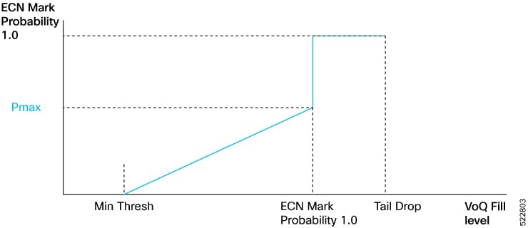
In buffer-internal mode, Explicit Congestion Notification (ECN) acts as an early congestion notifier within the PFC control loop. It gradually signals congestion to senders through ECN markings before resorting to link-level pause or packet drops.

Summary

The figure, ECN Mark Probability vs. Queue Length (VOQ Fill Levels) illustrates the progressive relationship between queue depth and router response:

  • ECN Min threshold: Start of the probabilistic marking region

  • ECN Max threshold : End of the linear region; ECN marking probability reaches Pmax

  • Pause threshold: Queue depth where PFC pause frames are triggered

  • Tail drop threshold: Final limit beyond which packets are dropped deterministically.

Workflow

Figure 1. ECN Mark Probability vs. Queue Length (VOQ Fill Levels)

The stages show how ECN, PFC, and tail drop operate sequentially as queue depth increases.

  1. Queue occupancy increases: The router monitors each traffic class queue within the Shared Memory System (SMS). ECN marking does not occur while depth is below the ECN Min Threshold.
  2. ECN marking begins (early warning): When queue depth exceeds the ECN Min Threshold, the router marks packets with ECN bits at a low probability. This action provides early congestion feedback to upstream devices.
  3. Marking probability rises linearly: As the queue grows from the ECN Min to Max threshold, marking probability increases linearly—from 0 percent to the configured Pmax value, for example, 5 percent.
  4. Full ECN marking region reached: After the ECN Max Threshold is crossed, marking probability becomes 1 (100%). Every packet is ECN-marked, but all traffic continues to be forwarded with no packet drops.
  5. Pause threshold reached (PFC activation): If congestion continues and queue depth reaches the configured pause threshold, the router sends PFC PAUSE frames to upstream devices for the affected traffic class. ECN marking stays active at 100%, while PFC halts incoming traffic temporarily to allow queues to drain.
  6. Tail drop protection: If the queue continues to grow and crosses the tail drop threshold, the router starts dropping packets deterministically. This action protects against buffer exhaustion when ECN and PFC feedback have not restored stability.
  7. Congestion clears: When queue depth falls below the ECN Min Threshold, ECN marking ceases, pause frames stop, and traffic resumes normal operation.
    When... Then... And...

    Queue depth < ECN min threshold

    Router does not mark packets

    Marking probability = 0%

    Queue depth ≥ ECN min threshold

    Router begins ECN marking

    Probability increases linearly

    Queue depth between ECN min and max

    ECN marking probability rises from 0% to Pmax

    Provides early congestion feedback

    Queue depth ≥ ECN max threshold but < pause threshold

    All packets are ECN-marked

    No packet drops yet

    Queue depth ≥ pause threshold

    Router sends PFC pause frames

    ECN marking continues at 100%

    Queue depth ≥ Tail-Drop Threshold

    Router drops packets deterministically

    Protects against buffer overflow

    Queue depth < ECN Min Threshold (after drain)

    ECN marking and pause actions cease

    Normal operations resume

PFC buffer internal mode configuration options and behaviors

You configure the max-threshold and probability-percentage options for this feature within the hw-module profile priority-flow-control command.

This feature gives you the flexibility to choose one of the following configuration options:

  • Default max-threshold and probability-percentage values

  • User-defined (configurable) max-threshold and probability-percentage values

  • Priority Flow Control (PFC) in buffer-internal mode without these new options, as supported in releases prior to Release 7.5.4.

Table 5. Useful Tips

If you...

...you must...

Want to switch from the default configuration mode to the custom configuration mode

OR

Want to switch from the custom configuration mode to the default configuration

  1. Use the no form of the hw-module profile priority-flow-control command to remove the existing configuration.

  2. Configure the new mode and settings using the hw-module profile priority-flow-control command.

  3. Reload the line card

Configured PFC in buffer-internal mode without configuring the max-threshold and probability-percentage parameters, but now want to configure them

  1. Configure the max-threshold and probability-percentage parameters using the hw-module profile priority-flow-control command.

  2. Reload the line card.

Want to change the buffer-internal parameters in the custom mode

Configure the buffer-internal parameters using the hw-module profile priority-flow-control command. You do not need to reload the line card.

Want to continue configuring PFC in buffer-internal mode the way you did in releases prior to Release 7.5.4

Configure the buffer-internal parameters using the hw-module profile priority-flow-control command, but ensure that you only configure values for pause-threshold , headroom , and ecn . If you don't configure values for max-threshold , the router takes the ecn value as the ECN maximum threshold value.

For more details, refer to Option 3 in the section titled Configure ECN threshold and maximum marking probability values.

Best practices for configuring ECN threshold and marking probability

Follow these principles to ensure that configuration is consistent and operation is predictable for Explicit Congestion Notification (ECN) thresholds and marking probabilities within Priority Flow Control (PFC).

  • Mode dependency: This functionality is supported only when PFC is configured in buffer-internal mode.

  • ECN value derivation: If you configure PFC values in the buffer-internal mode, the ECN value for the line card is derived from the buffer-internal configuration, unlike in the buffer-extended mode where the ECN value is derived from the policy map.

  • Hardware Support:

    Supported line cards include:

    • 88-LC0-36FH

    • 88-LC0-36FH-M

  • Supported interface types include:

    • Physical interfaces

    • Bundle interfaces

    • Subinterfaces

    • Bundle subinterfaces

  • Interface speeds: This functionality is supported across all interface speeds.

  • Policy map applicability:

    If your policy map enables maximum ECN marking probability for one or more classes, you can:

    • apply the map to any of the supported interface types

    • remove the map from any of the supported interface types

    • modify the map while you’re attaching it to multiple interfaces.

  • Class configuration dependency: The probability percentage option is valid only when random-detect ecn is configured in the same class. Otherwise, the policy is rejected when applied.

  • Device level consistency: Ensure that the configured probability percentage value is identical for all traffic classes, because this setting is enforced at the device level.

Configure ECN threshold and maximum marking probability values

Use this task to configure the Explicit Congestion Notification (ECN) thresholds and marking probability values for Priority Flow Control (PFC) operating in buffer-internal mode.

Depending on your network requirements, you can choose the default options, custom options, or use the existing configuration without the new options

In buffer-internal mode, you can configure PFC with adjustable ECN thresholds to optimize congestion control. You can manage queue behavior by defining the minimum and maximum thresholds and the marking probability.

The task supports three configuration paths:

  • Option 1: Default configuration mode (uses predefined ECN and marking values)

  • Option 2: Custom configuration mode (you define every parameter, including max-threshold and probability-percentage )

  • Option 3: Configuration without the new options, as used before Release 7.5.4.

Before you begin

  • Ensure that PFC is enabled on the router.

  • Confirm that the buffer-internal mode is enabled.

Follow these steps to configure ECN threshold and maximum marking probability values.

Procedure


Step 1

Enable PFC on the interface.

Example:

Router(config)#interface FourHundredGigE0/6/0/1
Router(config-if)#priority-flow-control mode on

Step 2

Choose one configuration option that meets your requirements.

  • Option 1: Default configuration mode
    Configure PFC in buffer-internal mode using predefined buffer values and default ECN thresholds.
    Router(config)#hw-module profile priority-flow-control location 0/6/0/1
    Router(config-pfc-loc)#buffer-internal traffic-class 3
    Router(config-pfc-loc)#buffer-internal traffic-class 4
    Router(config-pfc-loc)#commit
    

    This mode applies the system’s default max-threshold and probability-percentage values for ECN.

  • Option 2: Custom configuration modeConfigure PFC in buffer-internal mode with custom thresholds for all parameters, including max-threshold and probability-percentage.
    Router(config)#hw-module profile priority-flow-control location 0/6/0/1
    Router(config-pfc-loc)#buffer-internal traffic-class 3 pause-threshold 1574400 bytes headroom 1651200 bytes ecn 629760 bytes max-threshold 1416960 bytes probability-percentage 50
    Router(config-pfc-loc)#buffer-internal traffic-class 4 pause-threshold 1574400 bytes headroom 1651200 bytes ecn 629760 bytes max-threshold 1416960 bytes probability-percentage 50
    Router(config-pfc-loc)#commit
    

    You define all thresholds and probabilities. This option provides the highest control over ECN marking behavior.

  • Option 3: Configuration mode without ECN enhancements

    Configure PFC in buffer-internal mode without max-threshold and probability-percentage parameters.

    Router(config)#hw-module profile priority-flow-control location 0/6/0/1
    Router(config-pfc-loc)#buffer-internal traffic-class 3 pause-threshold 1574400 bytes headroom 1651200 bytes ecn 629760 bytes
    Router(config-pfc-loc)#buffer-internal traffic-class 4 pause-threshold 1574400 bytes headroom 1651200 bytes ecn 629760 bytes
    Router(config-pfc-loc)#commit
    

    This option uses configurations prior to Release 7.5.4.

    If you do not configuring max-threshold , the router uses the ECN threshold value as the ECN maximum threshold.

Step 3

Verify the configuration.

Example:

Router#show controllers npu priority-flow-control location all
  • Option 1: Default configuration
    Location: 0/6/CPU0
    PFC: Enabled
    PFC Mode: buffer-internal
    TC  Pause-threshold  Headroom  ECN      ECN-MAX  Prob-per
    ----------------------------------------------------------
    3   1574400 bytes    1651200   629760   1416960  5
    4   1574400 bytes    1651200   629760   1416960  5
    

    Both traffic classes (3 and 4) use the system defaults for ECN maximum threshold and marking probability (5 percent).

  • Option 2: Custom configuration modeConfigure PFC in buffer-internal mode with custom thresholds for all parameters, including max-threshold and probability-percentage.
    Location: 0/6/CPU0
    PFC: Enabled
    PFC Mode: buffer-internal
    TC  Pause-threshold  Headroom  ECN      ECN-MAX  Prob-per
    ----------------------------------------------------------
    3   1574400 bytes    1651200   629760   1416960  50
    4   1574400 bytes    1651200   629760   1416960  50


    The ECN max threshold (1416960 bytes) and marking probability (50 percent) reflect custom values.

  • Option 3: Configuration mode without

    max-threshold and probability-percentage parameters.

    Location: 0/6/CPU0
    PFC: Enabled
    PFC Mode: buffer-internal
    TC  Pause-threshold  Headroom  ECN      ECN-MAX        Prob-per
    ---------------------------------------------------------------
    3   1574400 bytes    1651200   629760   not-configured not-configured
    4   1574400 bytes    1651200   629760   not-configured not-configured


    Since max-threshold and probability-percentage are not configured, these fields display not-configured , and the ECN threshold functions as the effective maximum threshold.


You have successfully configured ECN thresholds and marking probabilities for buffer-internal mode. The router applies ECN marking and congestion feedback based on your chosen configuration option.

buffer-extended mode

A buffer-extended mode is a Priority Flow Control (PFC) operating mode that

  • allows pause-thresholds to be configured in the line card profile

  • requires Explicit Notification Congestion (ECN) and queue limit configuration in the interface’s egress queuing policies, and

  • applies consistently to all ports on the line card.

Supporting details for buffer-extended mode

  • Provides more flexibility than buffer-internal mode, since ECN and queue limits can differ per interface.

  • Recommended for long-haul PFC peers, such as data center interconnects over 1 km.

  • Queue-limit and ECN configurations in policies take effect, unlike buffer-internal mode where they are ignored.

Lane traffic analogy for buffer-extended mode

Each lane still has its own small holding bay, but the city traffic authority sets one common stop line for everyone. This is the pause-threshold defined in the line-card profile.

Each lane’s local signal controller (the interface-level QoS policy) decides when to flash its yellow warning light, which is the ECN threshold that each interface can tune separately.

So, while all lanes share the same stop rule, each lane can warn drivers earlier or later depending on how busy it gets.

Best practices for configuring buffer-extended mode

buffer-extended mode threshold ranges

Set the pause-threshold value range for buffer-extended mode between 2 milliseconds (ms) and 25 ms or from 2000 microseconds (μs) and 25000 μs.

Guidelines to configure buffer-extended mode

Follow these guidelines to ensure a stable Priority Flow Control (PFC) configuration in the buffer-extended mode.
  • For Cisco 8808 and Cisco 8812 chassis, configure Priority Flow Control (PFC) thresholds on all line cards in the chassis.

  • Reload the line card whenever you add or remove a traffic class.

  • Add or remove ECN configuration using the hw-module profile priority-flow-control command. Then, reload the line card to apply the ECN changes.

  • For line card 88-LC0-36FH-M, use kilobytes (KB) or megabytes (MB) for both pause and headroom thresholds. The headroom value range is 4 to 75,000.

  • For line card 8800-LC-48H, use milliseconds (ms) or microseconds (μs) for pause thresholds. Do not configure headroom values. Always use ms or μs even if KB or MB are shown in the CLI.

Restrictions while configuring buffer-extended mode

Enforce these restrictions while configuring the buffer-extended mode thresholds.
  • Ensure the ECN threshold value is less than the pause threshold value.

  • Ensure that the combined configuration values for pause threshold and headroom do not exceed 844,800 bytes; otherwise, the configuration is rejected.

  • Configure only one of buffer-internal, buffer-extended, or buffer-extended hybrid mode on each line card.

Configure buffer-extended thresholds

Use this task to configure Priority Flow Control (PFC) pause-thresholds in the line-card profile and define Explicit Congestion Notification (ECN) and queue-limit parameters in interface-level QoS policies.

buffer-extended mode separates global pause configuration from per interface congestion control:

  • Pause thresholds are configured once in the line-card profile.

  • ECN and queue limits are set per interface in QoS policies.

This enables fine-grained traffic management across multiple interfaces on the same line card.

Before you begin

  • The router must already be configured for buffer-extended mode.

  • PFC must be globally enabled (priority-flow-control mode on ).

Follow these steps to configure buffer-extended thresholds.

Procedure


Step 1

Enter the line card PFC profile and enable buffer-extended mode.

Example:

Router(config)#hw-module profile priority-flow-control mode buffer-extended

Step 2

Specify the pause-threshold value for the desired traffic class.

Example:

Router(config-pfc-profile)#traffic-class 3
Router(config-pfc-profile-tc)#pause-threshold 2000 us
  • All pause-threshold values configured under this profile will apply uniformly to every port on that line card.

  • This step defines the point at which PFC sends a pause frame upstream for traffic class 3 when congestion is detected.

  • The unit (μs, ms, KB, or MB) depends on your specific Cisco 8000 router, but the function remains the same: this value triggers pausing traffic on the specified class of service (CoS).

Step 3

(Optional) Configure additional buffer parameters if supported by your line card.

Example:

Router(config-pfc-profile-tc)#headroom 600 KB

  • On some Cisco 8000 routers, you can explicitly reserve additional buffer space beyond the pause threshold (called headroom) to absorb packets already in flight when a pause frame is issued.

  • On hardware where headroom is not configurable, this step is omitted.

Step 4

Create or edit the interface-level QoS policy to define ECN thresholds.

Example:

Router(config)#policy-map qos-policy
Router(config-pmap)#class COS_3
Router(config-pmap-c)#random-detect min-threshold 200 KB max-threshold 400 KB probability 5
Router(config-pmap-c)#random-detect ecn
  • This step creates or edits the interface-level QoS policy that defines ECN thresholds and probabilities.

  • The random-detect command enables Weighted Random Early Detection (WRED), the mechanism that provides early congestion signaling before a PFC pause frame is triggered.

  • The min-threshold (200 KB) marks the queue depth where ECN marking begins.

  • The max-threshold (400 KB) is the queue depth where ECN marking probability increases to the configured probability (5 %).

  • Between these two points, the system automatically increases the marking probability in a linear fashion.

  • If ECN is enabled, packets are marked with ECN bits instead of being dropped.

  • If ECN is disabled, packet drops occur early to prevent queue buildup.

This configuration allows the router to signal congestion early, reducing the likelihood of abrupt PFC pauses and maintaining smoother traffic flow.

Step 5

Apply the QoS policy to the required interface.

Example:

Router(config)#interface HundredGigE0/0/0/2
Router(config-if)#service-policy output qos-policy
Router(config)#exit
Router(config)#commit
  • This step creates or edits the interface-level QoS policy that defines ECN thresholds and probabilities.

  • The random-detect command enables Weighted Random Early Detection (WRED), the mechanism that provides early congestion signaling before a PFC pause frame is triggered.

  • The min-threshold (200 KB) marks the queue depth where ECN marking begins.

  • The max-threshold (400 KB) is the queue depth where ECN marking probability increases to the configured probability (5%).

  • Between these two points, the system automatically increases the marking probability in a linear fashion.

  • If ECN is enabled, packets are marked with ECN bits instead of being dropped.

  • If ECN is disabled, packet drops occur early to prevent queue buildup.

This configuration allows the router to signal congestion early, reducing the likelihood of abrupt PFC pauses and maintaining smoother traffic flow.

Step 6

View pause thresholds applied on the line card.

Example:

Router#show controllers npu priority-flow-control location 0/1/CPU0
Traffic Class   Pause-Threshold   ECN Source   Status
3               2000 us           Policy-Map   Enabled
  • The configured traffic class (3) now uses a 2000 μs pause threshold.

  • The ECN source is listed as Policy-Map , confirming that ECN thresholds are coming from interface-level configuration.

  • The min-threshold (200 KB) marks the queue depth where ECN marking begins.

  • The max-threshold (400 KB) is the queue depth where ECN marking probability increases to the configured probability (5 %).

  • Between these two points, the system automatically increases the marking probability in a linear fashion.

  • If ECN is enabled, packets are marked with ECN bits instead of being dropped.

  • If ECN is disabled, packet drops occur early to prevent queue buildup.

This configuration allows the router to signal congestion early, reducing the likelihood of abrupt PFC pauses and maintaining smoother traffic flow.

Step 7

View ECN thresholds and queue limits on the interface.

Example:

Router#show policy-map interface HundredGigE0/0/0/2
Class-map: COS_3
  Random Detect (WRED):
    Min Threshold : 200 KB
    Max Threshold : 400 KB
    Probability   : 5 %
    Mark Type     : ECN
  • The configured ECN minimum and maximum thresholds are applied to the interface.

  • Mark Type : ECN confirms that early congestion notification is active instead of packet drops.

  • The min-threshold (200 KB) marks the queue depth where ECN marking begins.

  • The max-threshold (400 KB) is the queue depth where ECN marking probability increases to the configured probability (5 %).

  • Between these two points, the system automatically increases the marking probability in a linear fashion.

  • If ECN is enabled, packets are marked with ECN bits instead of being dropped.

  • If ECN is disabled, packet drops occur early to prevent queue buildup.

This configuration allows the router to signal congestion early, reducing the likelihood of abrupt PFC pauses and maintaining smoother traffic flow.


Configure PFC on interfaces

Use this task to enable Priority Flow Control (PFC) on supported line cards and interfaces, and to apply the classification and queuing policies that allow selected traffic classes to operate losslessly.

  • PFC must be enabled globally and per line card before it can be applied to traffic classes.

  • The operating mode (buffer-internal, buffer-extended, or buffer-extended hybrid) must be chosen at the line card profile level.

Before you begin

  • Install the supported line card.

  • Configure PFC on matching CoS values.

  • Ensure there are no breakout, bundle, or sub-interface configurations on PFC-enabled line cards.

Follow these steps to configure PFC on an interface.

Procedure


Step 1

Enable PFC globally.

Example:

Router(config)#priority-flow-control mode on

Step 2

Configure the line card profile for the required PFC mode.

Example:

Router(config)#priority-flow-control mode on
  • Option A: buffer-internal mode
     Router(config)#hw-module profile priority-flow-control mode buffer-internal
    Router(config-pfc-profile)#traffic-class 3
    Router(config-pfc-profile-tc)#pause-threshold 307200
    Router(config-pfc-profile-tc)#headroom 345600
    Router(config-pfc-profile-tc)#ecn-threshold 153600
    

    This option defines all threshold values directly in the LC profile so each traffic class uses fixed on-chip buffers.

  • Option B: buffer-extended mode
    Router(config)#hw-module profile priority-flow-control mode buffer-extended
    Router(config-pfc-profile)#traffic-class 3
    Router(config-pfc-profile-tc)#pause-threshold 2000 us
    
    • This option configures only the global pause-threshold in the line card profile while leaving Explicit Congestion Notification (ECN) and queue thresholds to interface policies.

    • This option centralizes pause control across the line card but allows per-interface tuning through QoS policies.

  • Option C: buffer-extended hybrid
    Router(config)#hw-module profile priority-flow-control hybrid-mode enable
    Router(config-pfc-profile)#hbm-buffers-percentage lossless 60 lossy 40
    Router(config-pfc-profile)#max-non-pfc-voqs 2500
    

    This option divides High Bandwidth Memory (HBM) between lossless and lossy traffic:

    • hbm-buffers-percentage allocates 60 percent of HBM to the lossless pool and 40 percent to lossy traffic.

    • max-non-pfc-voqs caps the number of lossy queues that share HBM resources.

    • The configuration takes effect after a router restart.

Step 3

Configure and attach classification and queuing policies.

Example:

Router(config)#policy-map pfc-ingress
Router(config-pmap)#class COS_3
Router(config-pmap-c)#priority-flow-control enable
Router(config)#policy-map qos-policy
Router(config-pmap)#class COS_3
Router(config-pmap-c)#random-detect min-threshold 200 KB max-threshold 400 KB probability 5
Router(config-pmap-c)#random-detect ecn
Router(config-pmap-c)#exit
Router(config-pmap)#exit
Router(config)#interface HundredGigE0/0/0/1
Router(config-if)#service-policy input pfc-ingress
Router(config-if)#service-policy output qos-policy
Router(config)#commit

This example:

  • creates a policy map named pfc-ingress to handle incoming traffic related to PFC.

  • defines a class named COS_3 inside the pfc-ingress policy map.

  • enables PFC processing on incoming traffic for COS_3 .

  • creates another policy map named qos-policy to apply QoS mechanisms to outgoing traffic.

  • defines a class named COS_3 within the qos-policy policy map.

  • configures Random Early Detection (RED), min-threshold , max-threshold , and the probability of dropping packets for COS_3 traffic.

  • enables Explicit Congestion Notification (ECN) in conjunction with RED.

  • applies the pfc-ingress policy map to the input direction of the HundredGigE0/0/0/1 interface. This means that any traffic arriving on this interface will be evaluated against the pfc-ingress policy, and the router will honor incoming PFC pause frames for COS_3 traffic.

  • applies the qos-policy policy map to the output direction of the HundredGigE0/0/0/1 interface. This means that any traffic being transmitted out of this interface will be evaluated against the qos-policy , and the RED or ECN mechanisms will be applied to COS_3 traffic to manage congestion.

Step 4

Verify the hardware-level PFC profile configuration on a specific line card.

Example:

Router#show controllers npu priority-flow-control location 0/0/CPU0
Location: 0/0/CPU0
PFC Mode: buffer-internal

Traffic Class  Pause-threshold  Headroom  ECN-threshold  Tx Pause Frames
-------------  ---------------  --------  -------------  ---------------
3              307200           345600    153600         24

A non-zero and increasing Tx Pause Frames count indicates that the router's NPU is actively experiencing congestion for this traffic class and is sending pause frames to its neighbors. This is a key indicator that PFC is working as intended.

Step 5

View the PFC statistics for a specific interface.

Example:

Router#show controllers HundredGigE0/0/0/1 priority-flow-control
Priority flow control information for interface HundredGigE0/0/0/1:
Priority Flow Control:
Total Rx PFC Frames : 95
Total Tx PFC Frames : 102
Rx Data Frames Dropped: 0
CoS Status Rx Frames
--- ------ ----------
0   on     0
1   on     0
2   on     0
3   on     95
4   on     0
5   on     0
6   on     0
7   on     0
  • Total Rx PFC Frames : 95 indicates that this interface has received 95 PFC pause frames in total.

  • Total Tx PFC Frames : 102 indicates that this interface has transmitted 102 PFC pause frames in total.

  • Rx Data Frames Dropped: 0 indicates that the PFC mechanism is effectively preventing data frame drops on ingress due to congestion on this interface.

Step 6

To view the consolidated statistics for all interfaces on the router, see View global statistics for Priority Flow Control and Priority Flow Control watchdog.


High Bandwidth Memory congestion detection

High Bandwidth Memory (HBM) congestion detection is a Priority Flow Control (PFC) congestion monitoring functionality that

  • helps monitor buffer occupancy across the Shared Memory System (SMS) and High-Bandwidth Memory (HBM)

  • detects when Virtual Output Queue (VOQ) spillover into HBM indicates congestion, and

  • records time-stamped congestion events and history for post-event analysis and troubleshooting.

Table 6. Feature History Table

Feature Name

Release Information

Feature Description

Detect High Bandwidth Memory Congestion

Release 25.1.1

Introduced in this release on: Fixed Systems (8700 [ASIC:K100])(select variants only*)

This feature is now supported on Cisco 8712-MOD-M routers.

Detect High Bandwidth Memory Congestion

Release 24.4.1

Introduced in this release on: Fixed Systems (8200 [ASIC: P100], 8700 [ASIC: P100])(select variants only*); Modular Systems (8800 [LC ASIC: P100])(select variants only*)

*This feature is supported on:

  • 8212-48FH-M

  • 8711-32FH-M

  • 88-LC1-36EH

  • 88-LC1-12TH24FH-E

  • 88-LC1-52Y8H-EM

Detect High Bandwidth Memory Congestion

Release 7.5.3

We provide detailed insights into congestion on the High Bandwidth Memory (HBM), such as the devices on which congestion has occurred, the time stamps, and when the device returned to its normal state. With such details, you can investigate the cause of congestion and identify the source ports causing congestion for future preventive actions.

You must configure PFC in the buffer-extended mode for this option.

The feature introduces the following to enable the option to detect HBM congestion:

It also introduces the following to view the congestion and memory usage details:

How HBM congestion detection works

This process explains how queue congestion moves from the Shared Memory System (SMS) to the High-Bandwidth Memory (HBM) on your router. It also describes how the HBM congestion detection feature captures buffer utilization details for post-congestion analysis.

Summary

The key components involved in High Bandwidth Memory congestion detection are:

  • Shared Memory System (SMS): the on-chip buffer where queues are normally stored and monitored for occupancy thresholds.

  • High Bandwidth Memory (HBM): the external, off-chip buffer that temporarily stores excess packets evicted from SMS during congestion.

  • Virtual Output Queues (VOQs): logical queues that carry per-class traffic from SMS to HBM.

  • Detection logic within the NPU: tracks queue depth, HBM use, and packet age to identify congestion.

Workflow

These stages describe how HBM congestion detection works.

  1. Normal queue operation: Under normal conditions, packets egressing from an interface are enqueued into the Shared Memory System (SMS), the router's on-chip buffer memory.
  2. Onset of congestion: When congestion begins, the SMS continues to buffer packets until queue occupancy exceeds per queue usage criteria. These criteria are based on two parameters.
    • Buffer space threshold per VOQ, and
    • Packet age, measured in milliseconds.
  3. Eviction to HBM: Once the usage threshold is crossed, the router evicts packets from the SMS to the HBM.
  4. Accumulation of HBM load: A sustained HBM load marks the onset of HBM congestion conditions.
  5. HBM congestion metrics: By configuring the command hw-module profile npu memory buffer-extended bandwidth-congestion-detection enable, you can view information such as devices on which congestion has occurred and the timestamps, and the current as well as highest buffer memory usage watermark since the last reading.

Result

Use this information for post-event analysis and reporting.

Best practices for HBM congestion detection

Use these practices to ensure accurate monitoring when enabling High Bandwidth Memory (HBM) congestion detection on your router.

  • Priority Flow Control mode: You must configure Priority Flow Control (PFC) in buffer-extended mode to enable this functionality.

  • Line card reload: No line card reload is required after running the hw-module profile npu memory buffer-extended bandwidth-congestion-detection enable command.

  • Supported hardware: This functionality is supported on:

    • Cisco Silicon One Q200-based routers and line cards

    • 8201-32FH routers

    • 88-LC0-48TH-MO, 88-LC0-36FH, and 88-LC0-36FH-M line cards

Configure High Bandwidth Memory congestion detection

Capture congestion events and memory usage data for High Bandwidth Memory (HBM) and Shared Memory System (SMS).

Before you begin

Enable Priority Flow Control (PFC) buffer-extended mode.

Follow these steps to enable HBM congestion detection and view the details.

Procedure


Step 1

Enable congestion detection.

Example:

Router#configure
Router(config)#hw-module profile npu buffer-extended location 0/6/CPU0
bandwidth-congestion-detection enable
Router(config)#commit
Router(config)#exit

Line card reload is not required.

Step 2

View the buffer usage and HBM congestion details.

If ...

Then...

You want to view buffer details

Run

  • show controllers npu packet-memory usage instance all location all

  • show controllers npu packet-memory usage verbose instance all location all

Note

 
  • These commands provide data for the current use and the highest watermark reached since the last reading for both SMS and HBM.

  • The refresh interval for the information is 30 seconds.

You want to view HBM bandwidth congestion

Run

  • show controllers npu packet-memory congestion instance all location all

  • show controllers npu packet-memory congestion detail instance all location all

  • show controllers npu packet-memory congestion verbose instance all location all

Note

 
  • These commands provide data for when the HBM congestion occurred or is about to happen.

  • The output maintains a history of the last 120 events regardless of the elapsed time.

  • The refresh interval for new events to be added is 30 seconds.

  • View the buffer details.
    Router#show controllers npu packet-memory usage instance all location all
    HW memory Information For Location: 0/6/CPU0
     
    -------------------------------------------------------------------------------------
    Timestamp(msec)                  | Device | Buff-int | Buff-int | Buff-ext | Buff-ext
                                                Usage      Max WM   | Usage    | Max WM
    -------------------------------------------------------------------------------------
    Wed 2022-09-21 01:54:11.154 UTC       0          7          8          0          0
    Wed 2022-09-21 01:54:12.154 UTC       0          7          8          0          0
    Wed 2022-09-21 01:54:24.023 UTC       1         22         22          0          0
    Wed 2022-09-21 01:54:34.088 UTC       2         11         12          0          0
    Wed 2022-09-21 01:54:35.088 UTC       2         11         12          0          0
    Wed 2022-09-21 01:54:36.088 UTC       2         11         12          0          0
    Wed 2022-09-21 01:54:37.088 UTC       2         11         12          0          0
    Wed 2022-09-21 01:54:38.089 UTC       2         11         12          0          0
    Wed 2022-09-21 01:54:39.089 UTC       2         11         12          0          0
    Wed 2022-09-21 01:54:40.089 UTC       2         11         12          0          0
    

    This example displays:

    • The timestamp at which data is sampled.

    • The network processor name (Device ).

    • The packet memory usage for that timestamp for SMS (Buff-int Usage in units of buffers) and HBM (Buff-ext Usage in units of 8 KB blocks).

    • The highest maximum watermark reached for SMS (Buff-int Max WM ) and HBM (Buff-ext Max WM ) since the last reading.

  • View the timestamp in milliseconds and the buffer details.
    Router#show controllers npu packet-memory usage verbose instance all location all 
    
    HW memory Information For Location: 0/RP0/CPU0
    
    * Option 'verbose' formatted data is for internal consumption.
    --------------------------------------------------------------------
    Timestamp(msec) | Device | Buff-int | Buff-int | Buff-ext | Buff-ext
                               Usage      Max WM   | Usage    | Max WM
    --------------------------------------------------------------------
       1663958881006       0       2455       2676        637        640
       1663958882007       0       2461       2703        635        640
       1663958883007       0       2364       2690        635        640
       1663958884007       0      71603      75325       3183      18336
       1663958885008       0       2458       2852       1275       1279
       1663958886008       0       2484       2827       1275       1279
    
  • Check if HBM congestion has occurred and view the timestamp of the congestion state.
    Router#show controllers npu packet-memory congestion instance all location all 
    HW memory Information For Location: 0/6/CPU0
     
    ----------------------------------------------------------------
    Timestamp(msec)                   |      Buff-ext       | Device 
                                      |      Event Type     |        
    ----------------------------------------------------------------
    Wed 2022-09-21 02:14:41.709 UTC            Congest         1
    Wed 2022-09-21 02:14:41.959 UTC            Congest         1
    Wed 2022-09-21 02:14:42.960 UTC            Congest         1
    Wed 2022-09-21 02:14:43.960 UTC            Congest         1
    Wed 2022-09-21 02:14:45.210 UTC            Congest         1
    Wed 2022-09-21 02:14:45.710 UTC            Congest         1
    Wed 2022-09-21 02:14:47.711 UTC            Normal          1
    

    The system displays the last 120 events and adds new events every 30 seconds. To view updated data, run the command again.

    After 120 events, the system replaces the oldest event with the newest. You cannot remove events from the list.

  • View additional details about HBM congestion.
    Router#show controllers npu packet-memory congestion detail instance all location all
    Fri Sep 23 18:49:50.640 UTC
    HW memory Information For Location: 0/RP0/CPU0
    
    * Option 'detail' formatted data is for internal consumption.
    -----------------------------------------------------------------------------------------------------------------------------------------------------------------
    Timestamp(msec)                  |      Buff-ext         | Device | Slice |    VOQ |VOQ-buff| Evicted-buff | Buff-int | Buff-int | Buff-int | Buff-ext | Buff-ext
                                     |      Event Type       |                         |int-WM  | int-WM       | UC-WM    | Usage    | Max WM   | Usage    | Max WM
    -----------------------------------------------------------------------------------------------------------------------------------------------------------------
    Fri 2022-09-23 18:42:30.349 UTC                Congest        0        5      534    16011        63969        65451      70410      70410       34405    34405
    Fri 2022-09-23 18:42:31.101 UTC                 Normal        0        5      534        0            0          900       2440       2440           0        0
    Fri 2022-09-23 18:42:37.354 UTC                Congest        0        5      534    16011        63984        65493      70573      70573       34408    34408
    Fri 2022-09-23 18:42:38.354 UTC                 Normal        0        5      534        0            0          915       2455       2455           0        0
    Fri 2022-09-23 18:42:44.606 UTC                Congest        0        5      534    16011        64002        65520      70081      70081       34532    34532
    …	…	…

    This example displays:

    • The network processor name (Device ) and the slice number (Slice ) for that device. Every network processor has a fixed number of slices, and each slice, in turn, has a set number of ports.

    • Single VOQ buffer and aggregated SMS VOQ buffers.

    • The packet memory usage for that timestamp for SMS (Buff-int Usage in units of buffers) and HBM (Buff-ext Usage in units of 8 KB blocks).

    • The highest maximum watermark reached for SMS (Buff-int Max WM ) and HBM (Buff-ext Max WM ) since the last reading.

  • View additional HBM congestion details.
    Router#show controllers npu packet-memory congestion verbose instance all location all
    HW memory Information For Location: 0/RP0/CPU0
    * Option 'verbose' formatted data is for internal consumption.
    -------------------------------------------------------------------------------------------------------------------------------------
    Timestamp(msec) |      Event | Device | Slice |    VOQ |VOQ-buff| Evicted-buff | Buff-int | Buff-int | Buff-int | Buff-ext | Buff-ext
                    |      Type  |                         |int-WM  | int-WM       | UC-WM    | Usage    | Max WM   | Usage    | Max WM
    -------------------------------------------------------------------------------------------------------------------------------------
    1663958550349          0         0        5      534     16011        63969        65451      70410      70410      34405     34405
    1663958551101          1         0        5      534         0            0          900       2440       2440          0         0
    1663958557354          0         0        5      534     16011        63984        65493      70573      70573      34408     34408
    1663958558354          1         0        5      534         0            0          915       2455       2455          0         0
    1663958564606          0         0        5      534     16011        64002        65520      70081      70081      34532     34532
    1663958565356          1         0        5      534         0            0          915       2417       2417          0         0
    
    
    This example also displays:
    • Event type, where 0 is single VOQ-based congestion and 1 is single VOQ-based congestion backoff (VOQ-buff int-WM ), 2 is congestion in aggregated SMS buffers for VOQ and 3 is congestion backoff in aggregated SMS buffers for VOQ (Evicted-buff int-WM ).

    • The buffer internal for unicast (Buff-int UC-WM ), which is for information only.


Check available Shared Memory System and High Bandwidth Memory buffers

By enabling instantaneous display of available or free buffers for Shared Memory System (SMS) and High Bandwidth Memory (HBM), you can analyze the congestion affecting buffer occupancy accurately, especially during rapid traffic fluctuations.

Before you begin

To detect HBM and SMS congestion, use the hw-module profile npu memory buffer-extended bandwidth-congestion-detection enable command.

Procedure


Step 1

Run the command to view buffer usage statistics.

Example:

Router#show controller npu packet-memory usage instance all location all 
HW memory Information For Location: 0/6/CPU0
 
---------------------------------------------------------------------------------------------------------------------
Timestamp(msec)                  | Device | Buff-int | Buff-int | Buff-ext | Buff-ext | Buff-int-free | Buff-ext-free
                                            Usage      Max WM   | Usage    | Max WM   | Min WM        | Min WM
---------------------------------------------------------------------------------------------------------------------
Wed 2023-08-30 23:47:40.918 UTC       0       1518       6668      17154      17656     293394          982846
Wed 2023-08-30 23:47:41.918 UTC       0       1227       5631      16010      16427     293685          983990
Wed 2023-08-30 23:47:42.919 UTC       0       1398       8295      15041      15734     293514          984959
Wed 2023-08-30 23:47:43.919 UTC       0       1765       8892      14744      15678     293147          985256
Wed 2023-08-30 23:47:41.011 UTC       1      10380      12419      37532      38165     284532          962468
Wed 2023-08-30 23:47:42.011 UTC       1      10463      11977      37315      38326     284449          962685
Wed 2023-08-30 23:47:43.013 UTC       1       9145      12604      37714      38242     285767          962286
Wed 2023-08-30 23:47:44.013 UTC       1      10996      13272      37429      38051     283916          962571

Step 2

Review the output. Focus on:

  • Buff-int-free Min WM (available SMS buffer)

  • Buff-ext-free Min WM (available HBM buffer)


The current availability of SMS and HBM buffers is displayed, allowing you to analyze congestion and buffer occupancy in real-time.

Available buffer in Shared Memory System and High Bandwidth Memory

This functionality provides instantaneous visibility of available, or free, buffer space in both Shared Memory System (SMS) and High Bandwidth Memory (HBM), complementing existing watermark data.

These counters for available buffers are accounted for in this way:

  • Available SMS buffer (Buff-int-free Min WM ) at a given instant= Maximum SMS buffer - highest maximum watermark reached for SMS (Buff-int Max WM )

  • Available HBM buffer (Buff-ext-free Min WM ) at a given instant = Maximum HBM buffer - highest maximum watermark reached for HBM (Buff-ext Max WM )

Table 7. Feature History Table

Feature Name

Release Information

Feature Description

Available Shared Memory System and High Bandwidth Memory Buffers

Release 25.3.1

Introduced in this release on: Fixed Systems (8200 [ASIC: P100], 8700 [ASIC: P100])(select variants only*); Modular Systems (8800 [LC ASIC: P100])(select variants only*)

*This feature is supported on:

  • 8711-32FH-M

  • 8212-48FH-M

  • 88-LC1-36EH

Available Shared Memory System and High Bandwidth Memory Buffers

Release 25.1.1

Introduced in this release on: Fixed Systems (8700 [ASIC:K100])(select variants only*)

This feature is now supported on Cisco 8712-MOD-M routers.

Available Shared Memory System and High Bandwidth Memory Buffers

Release 24.4.1

Introduced in this release on: Fixed Systems (8200 [ASIC: P100], 8700 [ASIC: P100])(select variants only*); Modular Systems (8800 [LC ASIC: P100])(select variants only*)

*This feature is supported on:

  • 8212-48FH-M

  • 8711-32FH-M

  • 88-LC1-36EH

  • 88-LC1-12TH24FH-E

  • 88-LC1-52Y8H-EM

Available Shared Memory System and High Bandwidth Memory Buffers

Release 24.1.1

You can now view buffer availability for Shared Memory System (SMS) and High Bandwidth Memory (HBM) with higher accuracy without any lag between the minimum and maximum watermark readings, especially when the packet buffers are used and released rapidly. This is possible because we’ve enabled the instantaneous display of available or free SMS and HBM.

Previously, you could view details only for the highest watermark readings for SMS and HBM.

You must configure PFC in the buffer-extended mode for this option, and this functionality is available only for Cisco Silicon One Q200-based routers and line cards.

This functionality modifies the following:

Global pause frames for High Bandwidth Memory congestion

A global pause frame (X-Off) for High Bandwidth Memory (HBM) congestion is a pause-protection functionality that

  • prevents packet drops on Priority Flow Control (PFC)–enabled queues when HBM bandwidth is saturated

  • ensures simultaneous pausing of all active lossless queues to maintain traffic integrity, and

  • preserves bandwidth guarantees during extreme congestion without impacting uncongested queues.

When HBM congestion occurs (see High Bandwidth Memory congestion detection), global pause frames (X-Off) are triggered for all PFC-enabled queues, regardless of whether those queues caused the congestion.

Idle queues that are not receiving traffic do not transmit X-Off signals.

This selective behavior ensures that congestion protection does not activate prematurely or unnecessarily, avoiding performance degradation in unaffected queues.

This functionality operates only when PFC is configured in buffer-extended mode and HBM congestion detection is enabled.

Table 8. Feature History Table

Feature Name

Release Information

Feature Description

Global Pause Frames for High Bandwidth Memory Congestion

Release 7.5.4 We ensure no packet drops on PFC-enabled queues due to High Bandwidth Memory (HBM) congestion. Such prevention of drops is possible because we have enabled the triggering of global pause frames (X-Off) whenever there's HBM congestion.

This functionality is disabled by default. You have the following options to enable it:

This feature introduces the show hw-module bandwidth-congestion-protect command to view the status of the global X-Off configuration.

Recommendations for configuring global pause frames for High Bandwidth Memory congestion

Follow these recommendations when enabling and configuring global pause frames (X-Off) for High Bandwidth Memory (HBM) congestion to ensure consistent lossless behavior and stable Priority Flow Control (PFC) operation.

  • Distance Limitation: This functionality is not supported when devices operating in buffer-extended mode are more than 0.5 km apart.

  • Headroom Limit: Configuring the command hw-module profile npu memory buffer-extended bandwidth-congestion-protect enable on line cards with headroom values greater than 6,144,000 bytes can cause a commit failure or prevent the feature from activating.

  • Reload Requirement: You must reload the line card after enabling the command hw-module profile npu memory buffer-extended bandwidth-congestion-protect enable for the configuration to take effect.

  • Supported Hardware: This functionality is supported only on 88-LC0-36FH and 88-LC0-36FH-M line cards.

Configure global pause frames for High Bandwidth Memory congestion

Use this procedure to enable and verify global pause frames (X-off) for High Bandwidth Memory (HBM) congestion on line cards configured with the buffer-extended mode.

This task ensures lossless behavior by pausing all Priority Flow Control enabled queues when HBM utilization crosses the congestion threshold.

This feature applies to buffer-extended mode. It prevents packet drops during extreme congestion by triggering a global X-off condition. You must reload the line card for the configuration to take effect.

Procedure


Step 1

Enable global pause (X-off) protection for HBM congestion.

Example:

Router#config
Router(config)#hw-module profile npu buffer-extended location 0/1/CPU0 bandwidth-congestion-protect enable
Router(config)#commit

Step 2

Verify global X-off configuration status.

Example:

Router#show hw-module bandwidth-congestion-protect location 0/1/CPU0
Location   Configured     Applied          Action         
-----------------------------------------------------------
0/1/CPU0     Yes             No               Reload

The table lists possible outputs for different command and commit actions.

Table 9. Command Output Scenarios

If you configured...

Configured field displays...

Applied field displays..

Then Action field displays...

Configure the hw-module profile npu memory buffer-extended command

Yes

No

Reload

Use the no form of the hw-module profile npu memory buffer-extended command after configuring it, but before reloading the line card

No

No

N/A

Configure the hw-module profile npu memory buffer-extended command for a supported variant and reload the line card

Yes

Yes, Active

Note


Yes indicates that the configuration is programmed to the hardware, Active indicates that the global X-off functionality is active on the hardware.

N/A

Use the no form of the hw-module profile npu memory buffer-extended command when it is active and commit without reloading the line card

No

Note


At this stage, the output displays the user action and not the hardware status.

No

Note


At this stage, the output displays the user action and not the hardware status.

Reload

Reload the line card after committing the no form of the hw-module profile npu memory buffer-extended command

No

Note


At this stage, the output displays the hardware status.

No

Note


At this stage, the output displays the hardware status.

N/A


buffer-extended hybrid mode

A buffer-extended hybrid mode is a Priority Flow Control (PFC) operating mode that

  • divides High Bandwidth Memory (HBM) into two independent pools—one for lossless traffic and another for lossy traffic,

  • enables larger HBM allocation (up to 8 GB per pool) for higher-capacity line cards, and

  • prevents lossy traffic from monopolizing buffer resources.

Supporting details for buffer-extended hybrid mode

In the absence of the buffer-extended hybrid mode, with both lossy and lossless traffic, lossy traffic classes experienced tail drops because the combined HBM usage exceeded the 4 GB limit.

The buffer-extended hybrid mode feature addresses this limitation.

  • Lossless traffic: Mapped to HBM pool 0 (operates in buffer-extended mode).

  • Lossy traffic: Mapped to HBM pool 1 (operates in buffer-internal mode).

  • Configuration knobs:

    • hbm-buffers-percentage to split the pools.

    • max-non-pfc-voqs to cap the number of lossy queues that can share HBM.

  • Telemetry: Pool statistics are visible in show controllers npu priority-flow-control outputs.

Lane traffic analogy for buffer-extended hybrid mode

The city adds an expressway divided into two distinct zones. One zone is reserved for priority vehicles (lossless traffic mapped to HBM pool 0) and another for regular traffic (lossy traffic mapped to HBM pool 1).

Both zones still follow the same central stop rules (pause-thresholds defined in the line-card profile), but they now draw from separate holding areas (dedicated HBM pools) so busy regular lanes do not block the priority lanes.

Within each zone, the local signal controllers (interface-level QoS policies) still decide when to flash their yellow warning lights (ECN thresholds), but the size of each zone’s holding area is set by the planners (HBM pool allocation using the hbm-buffers-percentage command).

Best practices for configuring buffer-internal hybrid mode

Follow these best practices to ensure correct and stable configuration of buffer-internal hybrid mode for PFC on supported line cards.

  • Lossless pool allocation: Allocate 50 to 80 percent of High Bandwidth Memory (HBM) to the lossless pool using the hbm-buffers-percentage lossless setting

  • Lossy pool allocation: Assign the remaining percentage to the lossy pool, ensuring the total allocation equals 100 percent.

  • VOQ maximum setting: Set max-non-pfc-voqs to a value between 1 and 3,800, according to system needs.

  • Buffer pool sizing: Ensure each buffer pool does not exceed 8 GB, depending on the line-card hardware.

  • Profile configuration order: Globally configure the buffer-extended hybrid mode profile before applying PFC or QoS policies.

  • HBM pool division: Specify the HBM percentage to divide the pool between lossless and lossy traffic, as required by your application.

  • Recommended lossless percentage for special traffic: Allocate a larger percentage (such as 60 to 70 percent) to the lossless pool when handling Remote Direct Memory Access (RDMA), storage, or latency-sensitive traffic.

  • Lossy queue cap: Adjust max-non-pfc-voqs to limit the number of lossy queues sharing HBM resources.

  • Router restart requirement: Restart the router after enabling buffer-extended hybrid mode for the configuration to take effect.

Configure buffer-extended hybrid mode with default settings

Use this procedure to configure buffer-extended hybrid mode with default settings.

Procedure


Step 1

Enter the configuration mode.

Example:

Router# configure

Step 2

Enter the configuration mode for PFC profiling on an interface.

Example:

Router(config)# hw-module profile priority-flow-control location 0/0/CPU0

Step 3

Enable buffer-extended PFC for traffic classes 3 and 4, indicating that these traffic classes are lossless and use dedicated buffer resources.

Example:

Router(config-pfc-profile)# buffer-extended traffic-class 3
Router(config-pfc-profile)# buffer-extended traffic-class 4

Step 4

Configure the non-PFC or lossy traffic classes to use the percentage of the available HBM buffers. In this example, the HBM percentage specified is 60.

Example:

Router(config-pfc-profile)# buffer-extended non-pfc-tcs hbm-buffers percentage 60
Router(config-pfc-profile)# !
Router(config-pfc-profile)# end

Step 5

Save the configuration.

Example:

Router(config)# commit

Step 6

Verify the configuration.

Example:

Router#show controllers npu priority-flow-control location 0/0/CPU0
Fri Mar 14 17:38:43.948 UTC
Location:               0/0/CPU0
PFC:                    Enabled
PFC Mode:               buffer-extended
PFC max evict Lossy:    24(Default)
TC    Pause-threshold    Headroom
---------------------------------
3   62914560 bytes     76800000 bytes
4   62914560 bytes     76800000 bytes
---------------------------------
TC    HbmPoolNum    TcGroup
---------------------------------
0          1             1
1          1             2
2          1             3
3          0             0
4          0             0
5          1             1
6          1             2
7          1             3
---------------------------------
Total hbm buffers           :    984576
Lossy Max hbm buffers per   :    60 (590745 buffers)
Lossless Max hbm buffers per:    40 (393830 buffers)
---------------------------------

Configure buffer-extended hybrid mode with user-specified settings

Use this procedure to configure buffer-extended hybrid mode with user-specified settings.

Procedure


Step 1

Enter the configuration mode.

Example:

Router# configure

Step 2

Enter the configuration mode for PFC profiling on an interface.

Example:

Router(config)# hw-module profile priority-flow-control location 0/0/CPU0

Step 3

Enable buffer-extended PFC for traffic class 3 and class 4, indicating that this traffic class is lossless and uses dedicated buffer resources.

Example:

Router(config-pfc-profile)# buffer-extended traffic-class 3
Router(config-pfc-profile)# buffer-extended traffic-class 4

Step 4

Configure the non-PFC or lossy traffic classes. It specifies that a maximum of 32 non-PFC VOQs can use 60% of the available HBM buffers.

Example:

Router(config-pfc-profile)# buffer-extended non-pfc-tcs max-non-pfc-voqs 32 hbm-buffers-percentage 60
Router(config-pfc-profile)# !
Router(config-pfc-profile)# end

Step 5

Save the configuration.

Example:

Router(config)# commit

Step 6

Verify the configuration.

Example:

Router#show running-config | include "hw-module|buffer"
Fri Aug 29 15:31:50.548 UTC
hw-module profile priority-flow-control location 0/0/CPU0
buffer-extended traffic-class 3
buffer-extended traffic-class 4
buffer-extended non-pfc-tcs max-non-pfc-voqs 32 hbm-buffers-percentage 60
Router#
Router#show controllers npu priority-flow-control location 0/0/CPU0
Fri Aug 29 15:31:55.165 UTC
 
Location:               0/0/CPU0
PFC:                    Enabled
PFC Mode:               buffer-extended
PFC max evict Lossy:    32
TC    Pause-threshold    Headroom
---------------------------------
3   62914560 bytes     76800000 bytes
4   62914560 bytes     76800000 bytes
---------------------------------
TC    HbmPoolNum    TcGroup
---------------------------------
0          1             1
1          1             2
2          1             3
3          0             0
4          0             0
5          1             1
6          1             2
7          1             3
---------------------------------
Total hbm buffers           :    984576
Lossy Max hbm buffers per   :    60 (590745 buffers)
Lossless Max hbm buffers per:    40 (393830 buffers)
---------------------------------
Router#

Configure buffer-extended hybrid mode

You can configure buffer-extended hybrid mode by using these configuration settings:

If..

In..

Then..

Example

You configure hbm-buffers-percentage

the default max-non-pfc-voqs setting

the router uses its pre-defined, default number of non-PFC VOQs.

You can assign X percent of HBM to regular traffic. The router then automatically decides how many of your regular traffic queues can share that X percent of HBM. In this setup, the router still works to separate lossless traffic and lossy traffic.

You specify a particular value for max-non-pfc-voqs along with the hbm-buffers-percentage

the user-specified max-non-pfc-voqs setting

you can explicitly limit the number of non-PFC VOQs that can use the specified percentage of HBM.

You can assign Y number of the regular traffic queues to use X percent of HBM. This gives you more direct control over how many lossy queues can access the allocated HBM space.