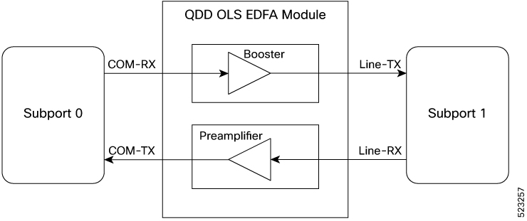
This topic explains how the COM and Line optical ports on the QDD OLS pluggable map to the optical transmission section (OTS) subport controllers, and identifies the booster and preamplifier associations used for configuration and troubleshooting.
The QDD OLS pluggable module includes two main physical ports—COM and Line—each represented by a separate optical transmission section (OTS) controller, known as subport 0 and subport 1. This mapping clarifies which optical ports and signal amplification functions are assigned to each controller. Use this mapping when configuring or troubleshooting the QDD OLS pluggable to ensure correct controller and port assignment for optical signal management.
Port and controller associations
This table shows how OTS controllers map to the QDD OLS optical ports:
|
Controller |
Optical Ports |
|---|---|
|
ots R/S/I/P/0 |
COM-RX (booster input) |
|
COM-TX (preamplifier output) |
|
|
ots R/S/I/P/1 |
LINE-RX (preamplifier input) |
|
LINE-TX (booster output) |
Each physical port has both RX and TX interfaces:
-
The COM port corresponds to subport 0.
-
The Line port corresponds to subport 1.
-
The booster amplifier gain is associated with the Line port (subport 1).
-
The preamplifier gain is associated with the COM port (subport 0).
Port and controller mapping in QDD OLS pluggable