Optics and Hardware Configuration Guide for Cisco 8000 Series Routers, Cisco IOS XR Releases

PDF

Optics and Hardware Configuration Guide for Cisco 8000 Series Routers, Cisco IOS XR Releases

Configure host side input loopback

Want to summarize with AI?

Log in

Provides instructions on how to configure host side input loopback in a controlled workflow. Covers prerequisites, execution steps, and result checks needed for successful completion.


In host loopback internal or host side input loopback, the loopback signal coming from the NPU is looped back to the NPU on the host, that is, towards the local interface. This is indicated by the arrows labeled as 1 and 2 in the illustration.
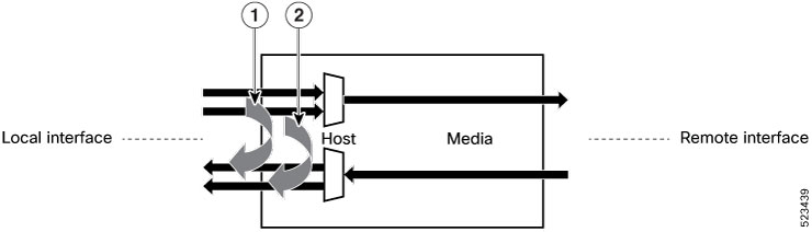
Figure 1. Host Side Input Loopback on the Optical Transceiver
Host Side Input Loopback on the Optical Transceiver

Procedure

1.

Configure host side input loopback.

Example:

Router#config
Router(config)#controller optics 0/0/0/9
Router(config-Optics)#secondary-admin-state maintenance
Router(config-Optics)#host loopback line
Loopback host is a traffic-affecting operation
Router(config-Optics)#commit
Router(config-Optics)#end
                        
2.

Display the running configuration for host side input loopback.

Example:

Router#show run controller optics 0/0/0/9
controller Optics0/0/0/9
 secondary-admin-state maintenance
 host loopback line
!
3.

Verify host side input loopback.

Example:

Router#show controller optics 0/0/0/9
Controller State: Up
Transport Admin State: Maintenance
Laser State: On
LED State: Green
FEC State: FEC ENABLED
Optics Status:

Optics Type: QSFPDD 400G FR4
Wavelength: 1301.00 nm
Loopback Host: Line
Loopback Media: None

Alarm Status:
----------------
Detected Alarms: None
LOS/LOL/Fault Status:
Performance Monitoring: Disable