Important. Results generated by AI. Before using results, verify accuracy and completeness.
Copy
Provides instructions on how to configure host side output loopback in a controlled workflow. Covers prerequisites, execution steps, and result checks needed for successful completion.
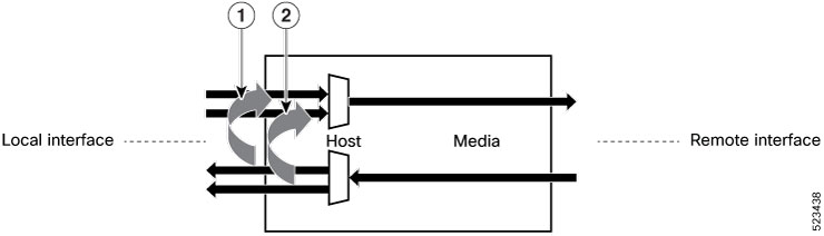
In host loopback line or host side output loopback, the signals received at the host side are looped back to the host side, indicating that the received data on the host is transmitted back to the host, that is, towards the local interface. This is indicated by the arrows labeled as 1 and 2 in the illustration.
Figure 1. Host Side Output Loopback on the Optical Transceiver
Procedure
1.
Configure host side output loopback.
Example:
Router#config
Router(config)#controller optics 0/0/0/9
Router(config-Optics)#secondary-admin-state maintenance
Router(config-Optics)#host loopback internal
Loopback host is a traffic-affecting operation
Router(config-Optics)#commit
Router(config-Optics)#end
2.
Display the running configuration for host side output loopback.