This topic explains the 8-channel and 16-channel optical line system configurations that the QDD OLS pluggable supports, including the cables, modules, port assignments, and node interconnections used to extend fiber bandwidth and span reach.
The QDD OLS pluggable enables transport of 8 or 16 coherent optical channels from DWDM optical modules installed in Cisco 8000 series routers. It interconnects optical modules with QDD OLS amplifiers to extend fiber bandwidth and span reach.
Supported cables for multi-channel optical line system
| Cable Name | Description | Purpose |
|---|---|---|
| ONS-BRK-CS-8LC | Dual fanout 1x8 cable-assembly with embedded passive splitter/coupler | Connects 8 modules to a QDD OLS pluggable |
| ONS-BRK-CS-16LC | Dual fanout 1x16 cable-assembly with embedded passive splitter/coupler | Connects 16 modules to a QDD OLS pluggable |
| ONS-CAB-CS-LC-5 | Dual adapter patch-cord, CS-connector to LC-connector | Connects two QDD OLS pluggables on different nodes |
8-channel optical line system
This section explains the 8-channel optical line system (OLS) that is achieved by using the QDD OLS pluggable and QDD-400G-ZR-S or QDD-400G-ZRP-S module.
Capabilities of the 8-channel optical line system
-
Achieves up to 28 dB / 112 kilometer span reach in the 8-channel OLS configuration
-
Increases fiber bandwidth utilization by up to 8 times compared to single-wavelength operation
Components for the 8-channel optical line system
This section explains the 8-channel optical line system (OLS) that is achieved by using the following:
-
Four Cisco 8000 series router (represented as Node A, Node B, Node C, and Node D)
-
Sixteen QDD-400G-ZR-S or QDD-400G-ZRP-S modules
-
Two QDD OLS (ONS-QDD-OLS) pluggables
-
Two ONS-BRK-CS-8LC breakout cables
-
Two ONS-CAB-CS-LC-5 fiber optic cable
Node port assignments of the 8-channel optical line system
| Node | Ports for QDD-400G-ZR-S/ZRP-S modules | Port for QDD OLS pluggable |
|---|---|---|
| A | 0, 1, 2, 3 | 4 |
| B | 0, 1, 2, 3 | – |
| C | 0, 1, 2, 3 | – |
| D | 0, 1, 2, 3 | 4 |
Interconnections of the 8-channel optical line system
-
Use an ONS-BRK-CS-8LC breakout cable to connect eight QDD-400G-ZR-S/ZRP-S modules (four from Node A and four from Node B) to the QDD OLS pluggable on Node A.
-
Use a second ONS-BRK-CS-8LC breakout cable to connect eight QDD-400G-ZR-S/ZRP-S modules (four from Node C and four from Node D) to the QDD OLS pluggable on Node D.
-
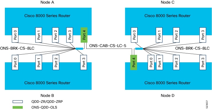
Use an ONS-CAB-CS-LC-5 fiber optic cable to connect the QDD OLS pluggables in Node A and Node D.
This image illustrates the 8-channel optical line system, component placement, and cabling.